WO2023238183A1 - Dehumidifier - Google Patents
Dehumidifier Download PDFInfo
- Publication number
- WO2023238183A1 WO2023238183A1 PCT/JP2022/022765 JP2022022765W WO2023238183A1 WO 2023238183 A1 WO2023238183 A1 WO 2023238183A1 JP 2022022765 W JP2022022765 W JP 2022022765W WO 2023238183 A1 WO2023238183 A1 WO 2023238183A1
- Authority
- WO
- WIPO (PCT)
- Prior art keywords
- housing
- control box
- opening
- dehumidifier
- compressor
- Prior art date
Links
- 230000007246 mechanism Effects 0.000 claims description 15
- 238000009423 ventilation Methods 0.000 claims description 8
- 230000001419 dependent effect Effects 0.000 claims 1
- 238000012423 maintenance Methods 0.000 description 19
- 239000003507 refrigerant Substances 0.000 description 19
- 238000010586 diagram Methods 0.000 description 12
- 230000005540 biological transmission Effects 0.000 description 9
- 238000004140 cleaning Methods 0.000 description 4
- 230000004048 modification Effects 0.000 description 4
- 238000012986 modification Methods 0.000 description 4
- 238000012546 transfer Methods 0.000 description 4
- 238000007689 inspection Methods 0.000 description 3
- XLYOFNOQVPJJNP-UHFFFAOYSA-N water Substances O XLYOFNOQVPJJNP-UHFFFAOYSA-N 0.000 description 3
- 230000006866 deterioration Effects 0.000 description 2
- 238000010438 heat treatment Methods 0.000 description 2
- 238000009434 installation Methods 0.000 description 2
- 230000002159 abnormal effect Effects 0.000 description 1
- 238000005452 bending Methods 0.000 description 1
- 230000008901 benefit Effects 0.000 description 1
- 238000013461 design Methods 0.000 description 1
- 238000007599 discharging Methods 0.000 description 1
- 238000006073 displacement reaction Methods 0.000 description 1
- 230000006870 function Effects 0.000 description 1
- 239000002184 metal Substances 0.000 description 1
- 238000012545 processing Methods 0.000 description 1
- 230000004044 response Effects 0.000 description 1
- 238000011144 upstream manufacturing Methods 0.000 description 1
Images


Classifications
-
- B—PERFORMING OPERATIONS; TRANSPORTING
- B01—PHYSICAL OR CHEMICAL PROCESSES OR APPARATUS IN GENERAL
- B01D—SEPARATION
- B01D53/00—Separation of gases or vapours; Recovering vapours of volatile solvents from gases; Chemical or biological purification of waste gases, e.g. engine exhaust gases, smoke, fumes, flue gases, aerosols
- B01D53/26—Drying gases or vapours
-
- F—MECHANICAL ENGINEERING; LIGHTING; HEATING; WEAPONS; BLASTING
- F24—HEATING; RANGES; VENTILATING
- F24F—AIR-CONDITIONING; AIR-HUMIDIFICATION; VENTILATION; USE OF AIR CURRENTS FOR SCREENING
- F24F2130/00—Control inputs relating to environmental factors not covered by group F24F2110/00
- F24F2130/20—Sunlight
Definitions
- the present disclosure relates to a dehumidifier.
- Patent Document 1 a configuration is known in which equipment such as an indoor unit is installed in a narrow space under the ceiling.
- equipment such as an indoor unit
- a blower and a heat exchanger are housed inside a main body forming an outer shell, and a decorative panel is provided on the lower surface of the main body.
- the decorative panel is integrally provided with an electrical box that houses electronic control parts for controlling the operation of the air conditioner. If a problem occurs with the electrical system, maintenance of the electrical box can be easily performed by opening the decorative panel from the indoor side, which is the air-conditioned space.
- Patent Document 1 Although the indoor unit disclosed in Patent Document 1 is installed in the ceiling, the worker performs maintenance work from the indoor side, which is the space to be air-conditioned, so the work space required for the worker is There is no problem in securing the
- a dehumidifier installed as a ceiling-mounted type in a narrow space behind the ceiling
- the refrigerant circuit components installed inside the outer casing, cleaning of the drain pan and heat exchanger, and the power line and transmission
- it is a problem to secure enough service space for the workers to perform their work.
- the present disclosure has been made in order to solve the above-mentioned problems, and even when installed in a narrow space such as in the ceiling, sufficient service space is secured for workers to perform their work.
- a dehumidifier that allows you to easily perform maintenance work such as replacing refrigerant circuit parts installed inside the housing, cleaning drain pans and heat exchangers, and connecting power lines and transmission lines from behind the ceiling. The purpose is to provide
- a dehumidifier includes a box-shaped casing having a front part in which an air outlet is formed and a back part in which a suction port is formed, a compressor disposed inside the casing, and a condensing a control box housing therein a control device for controlling at least the compressor, the expansion device, and the blower;
- An opening into which the control box is fitted is formed in a side surface that connects to the back surface, and the control box is fitted into the inside of the casing through the opening of the casing, and the control box is fitted into the inside of the casing through the opening of the casing. is attached to the side surface of the housing so as to be openable and closable.
- the present disclosure by removing the control box and opening the opening, it is possible to replace refrigerant circuit components installed inside the housing, clean the drain pan and heat exchanger, connect power lines and transmission lines, etc. maintenance work can be carried out. Therefore, even if the dehumidifier is installed in a narrow space such as a ceiling space, the maintenance work can be easily performed without securing a sufficient service space necessary for the work of the operator.
- FIG. 2 is a perspective view showing the appearance of the dehumidifier according to Embodiment 1 as seen from the front side of the casing, with the control box removed from the casing.
- 1 is a perspective view of the dehumidifier according to Embodiment 1, showing the appearance of the dehumidifier as seen from the back side of the housing.
- FIG. 2 is an explanatory diagram showing the internal configuration of the dehumidifier according to Embodiment 1, viewed from the top side of the housing.
- 1 is a perspective view of the dehumidifier according to Embodiment 1, showing the internal configuration as seen from the back side of the casing.
- 1 is a refrigerant circuit diagram showing an example of a configuration of a dehumidifier according to Embodiment 1.
- FIG. 1 is a refrigerant circuit diagram showing an example of a configuration of a dehumidifier according to Embodiment 1.
- FIG. 2 is an enlarged view of the main parts of the dehumidifier according to Embodiment 1, with the control box removed from the opening in the side surface.
- 1 is a perspective view of a control box of the dehumidifier according to Embodiment 1;
- FIG. FIG. 2 is an explanatory diagram of the dehumidifier according to the first embodiment, showing how a blower sucks air containing heat generated from a compressor and a control box.
- FIG. 2 is an enlarged view of the main parts of the dehumidifier according to Embodiment 1, showing a state in which a part of the cover member of the control box is removed from the box body fitted into the opening.
- FIG. 2 is an explanatory diagram showing an example of a service space provided around a conventional dehumidifier.
- FIG. 2 is an explanatory diagram showing a service space required for maintenance work on the dehumidifier according to the first embodiment.
- FIG. 7 is a perspective view of the appearance of the dehumidifier according to Embodiment 2 when viewed from the front side of the casing, with the side opening opened.
- FIG. 7 is an explanatory diagram showing the internal configuration of the dehumidifier according to Embodiment 2, viewed from the top side of the housing.
- FIG. 7 is a perspective view showing the appearance of the dehumidifier according to Embodiment 2 when viewed from the front side of the casing, and showing a different state in which an opening in the side surface is open.
- FIG. 7 is an enlarged view of main parts showing a first modification of the dehumidifier according to the second embodiment.
- FIG. 7 is a side view showing a second modification of the dehumidifier
- FIG. 1 is a perspective view showing the appearance of a dehumidifier 100 according to Embodiment 1 from the front side of the housing 1, with the control box 7 removed from the housing 1.
- FIG. 2 is a perspective view of the dehumidifier 100 according to the first embodiment, showing the external appearance of the housing 1 as viewed from the back side.
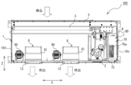
- FIG. 3 is an explanatory diagram showing the internal configuration of the dehumidifier 100 according to the first embodiment, viewed from the top side of the housing 1.
- FIG. 4 is a perspective view of the dehumidifier 100 according to the first embodiment, showing the internal configuration as seen from the back side of the housing 1.
- FIG. 5 is a refrigerant circuit diagram showing a configuration example of the dehumidifier 100 according to the first embodiment.
- the dehumidifier 100 As shown in FIGS. 1 to 4, the dehumidifier 100 according to the first embodiment has an approximately rectangular parallelepiped appearance as a whole, and is installed as a ceiling-mounted type in the ceiling, which is the space to be dehumidified, for example. It is.
- the dehumidifier 100 includes a compressor 2, a condenser 3, an expansion device 4 (see FIG. 5), an evaporator 5, and a blower 6 inside a box-shaped housing 1 that has a substantially rectangular parallelepiped appearance. , a control box 7, and a drain pan 8 are housed therein.
- the dehumidifier 100 has a refrigerant circuit in which a compressor 2, a condenser 3, an expansion device 4, and an evaporator 5 are sequentially connected through piping 9, and in which refrigerant circulates.
- the casing 1 is formed by processing a sheet metal into a substantially rectangular parallelepiped shape, for example.
- the housing 1 has a rectangular front part 10a and a back part 10b formed along the longitudinal direction X, and a front part 10a and a back part 10b formed along the lateral direction Z. It has left and right side portions 10c and 10d that connect, and an upper surface portion 10e and a lower surface portion (not shown).
- a suction port 11 for sucking air from a space to be dehumidified into the interior of the housing 1 is formed in the front portion 10 a of the housing 1 .
- Two air outlets 12 for discharging the air inside the housing 1 to the outside are formed on the back surface 10b of the housing 1 at intervals along the longitudinal direction X. As shown by the white arrows in FIGS. 3 and 4, inside the casing 1, the direction Z from the inlet 11 of the front part 10a to the outlet 12 of the back part 10b is the ventilation direction.
- the evaporator 5 is arranged along the suction port 11 formed in the back surface 10b, and the condenser 3 is arranged downstream of the evaporator 5 in the ventilation direction.
- the compressor 2 is located at a position that does not face the surface of the condenser 3 in the ventilation direction inside the housing 1 in order to avoid downstream air discharged from the condenser 3. It is disposed at a position facing the back surface 10b of the casing 1 away from the condenser 3. This is because the downstream air discharged from the condenser 3 has a high temperature.
- an air blower 6 and a motor 60 that drives the air blower 6 are arranged in the air outlet 12 formed in the back surface portion 10b. In the illustrated example, two blowers 6 and motors 60 are arranged in parallel.
- an opening 13 into which the control box 7 is fitted is formed in one of the left and right side surfaces 10c and 10d.
- the illustrated opening 13 is, for example, a square hole. Note that the opening 13 is not limited to the illustrated square hole, and may have other shapes.
- a support portion 14 is provided inside the housing 1 on which the control box 7 fitted into the opening 13 is placed and supported.
- the support portion 14 may be formed by bending a part of the side surface portion 10c along the opening edge of the opening portion 13, or a support stand made of a separate member from the housing 1 may be provided adjacent to the opening portion 13. It's okay.
- the support part 14 can be implemented in various shapes and sizes as long as it has a configuration that allows the control box 7 fitted in the opening part 13 to be placed and supported.
- the compressor 2 compresses the sucked refrigerant and discharges it in a high temperature and high pressure state.
- the compressor 2 is, for example, a positive displacement compressor that is configured to be able to vary its operating capacity and is driven by a motor that is controlled by an inverter.
- the condenser 3 functions as a reheater in the dehumidifier 100.
- the condenser 3 heats the air by exchanging heat between the high-temperature, high-pressure refrigerant discharged from the compressor 2 and flowing inside the heat transfer tube and the air dehumidified and cooled by the evaporator 5.
- the condenser 3 sucks in air using the blower 6, exchanges heat with the refrigerant, and discharges the air to the outside.
- the condenser 3 is provided with a plurality of fins through which the refrigerant flowing through the heat transfer tubes exchanges heat with air.
- the expansion device 4 depressurizes and expands the refrigerant flowing out from the condenser 3, and is composed of, for example, an electronic expansion valve that can adjust the opening degree of the throttle.
- the opening degree of the expansion device 4 is adjusted by a control device 72 provided inside the control box 7, and the pressure of the refrigerant flowing into the evaporator 5 is controlled.
- the evaporator 5 dehumidifies and cools the air by exchanging heat between the refrigerant flowing out from the expansion device 4 and flowing inside the heat transfer tube and the air sucked in from the space to be dehumidified.
- the evaporator 5 sucks in air using the blower 6, and discharges the air after exchanging heat with the refrigerant to the outside.
- the evaporator 5 is provided with a plurality of fins through which the refrigerant flowing through the heat transfer tubes exchanges heat with the air.
- the blower 6 for example, a centrifugal fan such as a sirocco fan is used.
- the blower 6 generates an airflow in the direction Z from the suction port 11 to the blowout port 12.
- the blower 6 is provided with a suction port 61 on the side surface on which the compressor 2 is disposed.
- the rotation speed of the blower 6 is controlled by the motor 60 being controlled by a control device 72 provided inside the control box 7 .
- the motor 60 is arranged on the side surface opposite to the side surface on which the suction port 61 is provided.
- the drain pan 8 is a container that is placed below the condenser 3 and the evaporator 5 and receives drain water generated from the evaporator 5.
- the bottom surface of the drain pan 8 is inclined from the front side 10a of the casing 1 toward the back side 10b to guide drain water toward the back side 10b of the casing 1. Further, the drain pan 8 is provided with a drain port 80 near the side surface 10c of the housing 1 for draining the accumulated drain water.
- FIG. 6 is an enlarged view of the main parts of the dehumidifier 100 according to the first embodiment, showing a state in which the control box 7 is removed from the opening 13 of the side surface 10c.
- FIG. 7 is a perspective view showing the box body 70 of the control box 7, which is the dehumidifier 100 according to the first embodiment.
- FIG. 8 is an explanatory diagram of the dehumidifier 100 according to the first embodiment, showing how air containing heat generated from the compressor 2 and the control box 7 is sucked in by the blower 6.
- FIG. 9 is an enlarged view of the main parts of the dehumidifier 100 according to the first embodiment, showing a state in which a part of the cover member 71 of the control box 7 is removed from the box body 70 fitted into the opening 13. It is.
- the control box 7 houses therein a control device 72 that controls the entire dehumidifier 100.
- the control box 7 is provided inside the housing 1 on the downstream side of the condenser 3 in the ventilation direction and next to the compressor 2 .
- the control box 7 has a concave box body 70 and a cover member 71 that covers the opening surface of the box body 70.
- a flange portion 70b that projects outward is formed at the opening edge of the box body 70. As shown in FIGS. 6 and 7, the flange portion 70b may be formed along the entire circumference of the opening edge of the box body 70, or may be formed along a part of the opening edge of the box body 70, although not shown. may be formed.
- the control device 72 is configured of, for example, a computer including a memory that stores data and programs necessary for control, and a CPU that executes the programs, dedicated hardware such as ASIC or FPGA, or both.
- the control device 72 controls each part of the entire dehumidifier 100 based on instructions from the remote controller 75. Specifically, the control device 72 controls the drive frequency of the compressor 2, the rotation speed of the blower 6, the opening degree of the expansion device 4, and the like. Further, a power line connected to a local power source is connected to the power terminal. Furthermore, a transmission line that is connected to the compressor 2, blower 6, and expansion device 4 and that transmits command information via the control device 72 is connected to the external input terminal.
- the box 70 is arranged so that the opening face faces the outside of the side surface 10c of the housing 1, and the recess is fitted into the opening 13 formed on the side surface 10c of the housing 1.
- the box 70 fitted into the opening 13 of the housing 1 is placed on the upper surface of the support section 14 provided inside the housing 1.
- the flange portion 70b comes into contact with the side surface portion 10c of the housing 1, and the flange portion 70b is attached to the side surface portion 10c with a joining member such as a screw.
- the box body 70 can be easily removed from the housing 1 by removing the joining member and pulling it out from the opening 13. When the box body 70 is removed, the inside of the housing 1 is opened.
- a worker can perform maintenance work such as replacing refrigerant circuit components installed inside the housing 1, cleaning the drain pan 8, condenser 3, and evaporator 5, and connecting power lines and transmission lines. It can be carried out.
- the dirty portion of the drain pan 8 can be easily cleaned through the opening 13.
- the box 70 is fitted into the opening 13, and the flange portion 70b is attached to the side surface portion 10c with a joining member such as a screw.
- exhaust holes 70a are formed in the upper and lower surfaces of the box body 70 when it is fitted into the interior of the housing 1.
- the exhaust hole 70a is, for example, a plurality of slits.
- the inside can be filled with a dehumidified atmosphere.
- the control box 7 can reduce moisture that causes deterioration or failure of electrical components and boards provided inside.
- the exhaust hole 70a does not necessarily need to be formed on the upper surface and the lower surface, but may be formed on at least the upper surface.
- control box 7 is preferably provided with a heat-resistant member 73 on the side surface of the box body 70 facing the compressor 2. This suppresses the situation in which parts constituting the control device 72 are directly heated through the side surface of the box body 70 by radiant heat generated by the compressor 2, and prevents failure of the control device 72. This is to do so.
- the compressor 2 and the blower 6 are arranged from the position of the control box 7 disposed on one side surface 10c toward the other side surface 10d of the housing 1.
- a control box 7, a compressor 2, and a blower 6 are arranged in this order.
- the blower 6 when the blower 6 is configured to suck air from the side facing the compressor 2 and the control box 7, the blower 6 sucks air containing heat from the compressor 2 and the control box 7. This is because it can be efficiently sucked in by combining with the wind flowing from the condenser 3 and discharged to the outside through the air outlet 12.
- the control box 7 is located further away from the compressor 2 with respect to the blower 6, and the air heated by the compressor 2 is sucked directly into the blower 6 without passing through the control box 7. Air rise inside the control box 7 can be suppressed. Note that, in order to secure an air path, it is desirable that no other member that obstructs the air path be disposed between the blower 6, compressor 2, and control box 7.
- the cover member 71 is a plate-shaped member that closes the opening surface of the box body 70.
- the cover member 71 includes a main cover part 71a that covers the opening surface of the box body 70 from above to near the bottom, and a sub-cover part 71b that covers the lower part of the opening surface of the box body 70.
- the main cover part 71a and the sub cover part 71b are configured to be detachable.
- the main cover portion 71a has a convex portion protruding downwardly formed on the lower edge thereof.
- the sub-cover part 71b is formed with a recessed part that fits into the convex part of the main cover part 71a.
- the cover member 71 is configured such that the convex portion of the main cover portion 71a and the recessed portion of the sub-cover portion 71b fit together, thereby making the main cover portion 71a and the sub-cover portion 71b removable.
- the cover member 71 may have a configuration in which a concave portion is formed along the lower edge of the main cover portion 71a, and a convex portion that fits into the concave portion of the main cover portion 71a is formed in the sub cover portion 71b.
- the cover member 71 is not limited to the above-mentioned uneven shape, but may have other configurations as long as the main cover portion 71a and the sub cover portion 71b are configured to be detachable.
- the sub-cover part 71b is formed with a power line for connecting the local power source and the control device 72, and a wiring hole 71c through which a transmission line from the remote control 75 is passed.
- a wiring hole 71c through which a transmission line from the remote control 75 is passed.
- two wiring holes 71c of different sizes are formed side by side on the left and right in the sub-cover part 71b.
- the control box 7 has a structure in which outside air is taken into the interior through the wiring hole 71c, takes away heat generated from the circuit elements of the control device 72, and discharges the heat into the inside of the casing 1 through the exhaust hole 70a on the top surface. ing.
- the control device 72 housed inside the box body 70 has, for example, a heating element with low heat resistance placed near the wiring hole 71c on the upstream side, and a heating element with low heat resistance placed near the exhaust hole 70a on the downstream side. It is desirable to arrange high heat generating elements. This is to efficiently exhaust the heat inside the control box 7. Further, the position, number, and size of the wiring holes 71c are not limited to the illustrated configuration, but may be changed as appropriate depending on the wiring situation.
- the cover member 71 is attached to the flange portion 70b of the box body 70 with a joining member such as a screw.
- the main cover part 71a and the sub-cover part 71b can be independently attached to the flange part 70b of the box body 70.
- the cover member 71 only the main cover part 71a can be removed from the box body 70, for example, while the sub cover part 71b remains attached to the box body 70. This makes it possible to perform maintenance work on the control device 72 installed inside the control box 7 while it is connected to the power supply line and transmission line, thereby eliminating the need to remove the power supply line and improving work efficiency for the operator. can be improved.
- cover member 71 is not limited to the structure having the main cover part 71a and the sub cover part 71b as illustrated.
- the cover member 71 may be composed of a single piece without providing the main cover part 71a and the sub-cover part 71b separately.
- FIG. 10 is an explanatory diagram showing an example of service spaces (200 to 202) provided around a conventional dehumidifier 300.
- FIG. 11 is an explanatory diagram showing a service space 200 required for maintenance work on the dehumidifier 100 according to the first embodiment.
- the service space 200 when securing a service space around the dehumidifier 300, the service space 200 is provided with an inspection port 200a where the side surface 10c of the housing 1 is located, and the suction port 11 is formed.
- a service space 201 located on the front surface 10a and a service space 202 located on the side surface 10d of the housing 1 are required.
- the service space 201 needs to have a width L1 along the width direction Z of the dehumidifier 300 as a suction space of 300 mm or more.
- the service spaces 200 and 202 need to have a width L2 of 500 mm or more along the longitudinal direction X of the dehumidifier 300.
- an opening 13 into which the control box 7 is fitted is formed in the side surface 10c that connects the front surface 10a and the back surface 10b of the housing 1.
- the control box 7 is fitted into the interior of the housing 1 through the opening 13 of the housing 1, and is attached to the side surface 10c of the housing 1 so that the opening 13 can be opened and closed.
- the dehumidifier 100 by removing the control box 7 from the housing 1 and opening the opening 13, the refrigerant circuit components installed inside the housing 1 can be cooled through the opening 13. Maintenance work such as replacement, cleaning of the drain pan 8, condenser 3 and evaporator 5, and connection of power lines and transmission lines can be performed. Therefore, as shown in FIG. 11, it is only necessary to provide a service space 200 near the side surface 10c in which the opening 13 into which the control box 7 is fitted is formed. Therefore, even if the dehumidifier 100 is installed in the attic, which is a narrow space, the maintenance work can be easily performed in the attic without securing a sufficient service space necessary for the operator's work. can. Furthermore, since there is no need to secure a sufficient service space, the service space that has been required up to now can be reduced, and the choice of installation location for the dehumidifier 100 is increased, such as in the ceiling where installation locations are restricted.
- a support portion 14 is provided inside the housing 1 on which the control box 7 fitted into the opening 13 is placed and supported. Therefore, in the dehumidifier 100 according to the first embodiment, the control box 7 can be easily fitted into the opening 13, and the control box 7 can be stably installed inside the housing 1.
- control box 7 includes a concave box body 70 and a cover member 71 that closes the opening surface of the box body 70.
- a flange portion 70b that projects outward is formed at the opening edge of the box body 70.
- the control box 7 has a structure in which a box body 70 is fitted into the opening 13 of the casing 1, and a flange portion 70b is attached to the side surface 10c of the casing 1. Therefore, in the dehumidifier 100 according to the first embodiment, the control box 7 can be firmly fixed to the housing 1 and installed.
- the cover member 71 has a main cover part 71a and a sub-cover part 71b that is detachably attached to the main cover part 71a.
- the cover member 71 is configured such that the main cover part 71a can be attached to and removed from the box body 70 while the sub cover part 71b is attached to the box body 70.
- a wiring hole 71c is formed in the sub-cover part 71b, through which a power line, etc. for connecting the local power source and the control device 72 is passed, it is possible to insert the wiring hole 71c inside the control box 7 with the power line etc. connected. Maintenance work can be performed on the installed control device 72. Therefore, the trouble of removing the power supply wire etc. is omitted, and the work efficiency of the worker can be improved.
- a heat-resistant member 73 is provided on the side surface of the control box 7 facing the compressor 2. This prevents the parts constituting the control device 72 from being directly heated through the side surface of the box body 70 by radiant heat generated from the compressor 2, and prevents the control device 72 from malfunctioning. This can be prevented.
- control box 7 has an exhaust hole 70a formed on the upper surface thereof when it is fitted into the housing 1.
- the control box 7 is disposed inside the housing 1 on the downstream side of the condenser 3 in the ventilation direction. Therefore, the interior of the control box 7 can be filled with a dehumidified atmosphere, thereby reducing moisture that causes deterioration or failure of electrical components and boards provided inside.
- the housing 1 when the housing 1 is viewed from the top side, there are a position where the exhaust hole 70a of the control box 7 is formed, a position where the compressor 2 is installed, and a suction port of the blower 6.
- the control box 7, the compressor 2, and the blower 6 are arranged so that the position where the control box 61 is formed is on a straight line.
- the blower 6 when the blower 6 is configured to draw in air from the side facing the compressor 2 and the control box 7, the blower 6 absorbs the air containing the heat of the compressor 2 and the control box 7 into the air flowing from the condenser 3. It can be efficiently sucked in by merging with the air and discharged to the outside through the air outlet 12.
- the control box 7 has a configuration in which outside air is taken into the interior through the wiring hole 71c and heat is exhausted to the outside through the exhaust hole 70a. Thereby, the heat inside the control box 7 can be efficiently discharged.
- the compressor 2 and the blower 6 are arranged from the position of the control box 7 disposed on one side surface 10c toward the other side surface 10d of the housing 1. 2.
- the blower 6 is arranged in this order. As a result, when the blower 6 is configured to draw in air from the side facing the compressor 2 and the control box 7, the blower 6 absorbs the air containing the heat of the compressor 2 and the control box 7 into the air flowing from the condenser 3. It can be efficiently sucked in by merging with the air and discharged to the outside through the air outlet 12.
- the compressor 2 is arranged at a position that does not face the surface of the condenser 3 in the ventilation direction inside the casing 1. As a result, the compressor 2 can be placed in a position away from the air discharged from the condenser 3 on the downstream side, where the temperature is high, so that an increase in the temperature of the compressor 2 can be suppressed.
- FIG. 12 is a perspective view of the appearance of the dehumidifier 101 according to the second embodiment as viewed from the front side of the housing 1, with the opening 13 of the side surface 10c open.
- FIG. 13 is an explanatory diagram showing the internal configuration of the dehumidifier 101 according to the second embodiment, viewed from the top side of the housing 1.
- FIG. 14 is a perspective view showing the external appearance of the dehumidifier 101 according to the second embodiment when viewed from the front side of the housing 1, and showing a different state in which the opening 13 of the side surface 10c is open.
- FIG. 12 is a perspective view of the appearance of the dehumidifier 101 according to the second embodiment as viewed from the front side of the housing 1, with the opening 13 of the side surface 10c open.
- FIG. 14 is a perspective view showing the external appearance of the dehumidifier 101 according to the second embodiment when viewed from the front side of the housing 1, and showing a different state in which the opening 13 of the side surface 10c is open.
- FIG. 15 is an enlarged view of main parts showing a first modification of the dehumidifier 101 according to the second embodiment.
- FIG. 16 is a side view showing a second modification of the dehumidifier 101 according to the second embodiment.
- 12 to 15 show a state in which the cover member 71 is removed from the box body 70. Note that the same components as those of the dehumidifier 100 described in Embodiment 1 are given the same reference numerals, and the description thereof will be omitted as appropriate.
- an opening into which the control box 7 is fitted is provided in the side surface 10c connecting the front surface 10a and the rear surface 10b. 13 are formed.
- the control box 7 is fitted into the interior of the housing 1 through the opening 13 of the housing 1, and is attached to the side surface 10c of the housing 1 so that the opening 13 can be opened and closed.
- a box body 70 is fitted into an opening 13 of a housing 1, and a flange portion 70b is joined to a side surface portion 10c of the housing 1 via a hinge mechanism portion 74. It is attached with parts.
- the box body 70 is configured such that the opening 13 of the housing 1 can be opened and closed with a portion of the side surface 10 c of the housing 1 being joined to a hinge mechanism 74 .
- 13 and 14 of the flange parts 70b formed around the box body 70, the flange parts 70b located on the front side and the back side of the housing 1 are attached via a hinge mechanism part 74.
- the other flange portion 70b is attached to the side surface portion 10c of the housing 1 using a joining member.
- the opening 13 of the housing 1 When opening the opening 13 of the housing 1, after removing the cover member 71 from the box 70, as shown in FIGS. The other joining members of the flange portion 70b are removed, leaving the remaining members. By doing so, the opening 13 of the casing 1 can be opened in a half-open state via the hinge mechanism 74 while the box 70 is attached to the side surface 10c of the casing 1.
- the opening 13 of the casing 1 when the opening 13 of the casing 1 is opened, the cover member 71 is removed from the box 70, and then the opening 13 of the casing 1 is opened.
- the joining member of the flange portion 70b located on the back side may be left, and the joining members of the other flange portion 70b may be removed.
- the opening 13 of the casing 1 can be opened in a half-open state via the hinge mechanism 74 while the box 70 is attached to the side surface 10c of the casing 1.
- the dehumidifier 101 has only the flange portion 70b located on the back side of the housing 1 among the flange portions 70b formed around the box body 70. They may be joined via the hinge mechanism section 74. Although not shown, only the flange portion 70b located on the front side of the housing 1 among the flange portions 70b formed around the box body 70 may be joined via the hinge mechanism portion 74. good. Even in this case, the opening 13 of the casing 1 can be opened in a half-open state via the hinge mechanism 74 while the box 70 is attached to the side surface 10c of the casing 1.
- a hinge mechanism part 74 is attached to the side surface 10c of the housing 1 together with the cover member 71. It may also be attached with a joining member via. By doing this, the opening 13 of the housing 1 can be opened via the hinge mechanism 74 while the control box 7 is attached to the side surface 10c of the housing 1 without removing the cover member 71 from the housing 70. It can be opened in a half-open state. Also in this case, of the flange portions 70b formed around the box body 70, only the flange portions 70b located on the front side or the back side of the housing 1 may be joined via the hinge mechanism portion 74. good.
- the cover member 71 shown in FIG. 16 is composed of one sheet, it may have a structure having a main cover part 71a and a sub-cover part 71b, as shown in FIGS. 1 and 6.
- control box 7 is partially joined to the hinge mechanism 74 on the side surface 10c of the housing 1, and the control box 7 is connected to the opening 13 of the housing 1. Since the control box 7 is configured to be openable and closable, there is no need to remove the control box 7, and there is no need to worry about where to put the removed control box 7, so the workability of maintenance work can be improved.
- the dehumidifiers 100 and 101 have been described above based on the embodiments, the dehumidifiers 100 and 101 are not limited to the configurations of the embodiments described above.
- the configurations of the dehumidifiers 100 and 101 described above are merely examples, and may include other components or may omit some components.
- the dehumidifiers 100 and 101 are not limited to a configuration in which they are installed as ceiling-mounted types in the ceiling which is the space to be dehumidified, but may be installed in a place other than the ceiling.
- the housing 1 is not limited to the illustrated rectangular parallelepiped shape, but may have other shapes. In short, the dehumidifiers 100 and 101 are subject to a range of design changes and application variations that are commonly made by those skilled in the art without departing from the technical concept thereof.
Landscapes
- Chemical & Material Sciences (AREA)
- Engineering & Computer Science (AREA)
- Analytical Chemistry (AREA)
- General Chemical & Material Sciences (AREA)
- Oil, Petroleum & Natural Gas (AREA)
- Chemical Kinetics & Catalysis (AREA)
- Drying Of Gases (AREA)
Abstract
This dehumidifier comprises: a box-shaped housing having a front face part in which an air outlet is formed and a back face part in which an air inlet is formed; a compressor, a condenser, an evaporator, an expansion device, and a blower arranged in the housing; and a control box that stores therein a control device for controlling at least the compressor, the expansion device, and the blower. The housing has formed therein an opening for fitting the control box in a lateral face part which connects the front face part and the back face part. The control box is fitted into the housing through the opening of the housing, and is attached to the lateral face part of the housing so as to be able to open/close the opening.
Description
本開示は、除湿機に関するものである。
The present disclosure relates to a dehumidifier.
従来、例えば特許文献1のように、室内機等の機器を狭い空間である天井裏に設置した構成が知られている。この室内機は、外郭を形成する本体の内部に送風機と熱交換器とが収容され、本体の下面に化粧パネルが設けられている。化粧パネルには、空調機の運転制御を行うための電子制御部品を収納した電装箱が一体的に設けられている。電気系統のトラブルが発生した場合には、空調対象空間である室内側から化粧パネルを開けることで、電装箱のメンテナンスを容易に行うことができる。
Conventionally, as in Patent Document 1, for example, a configuration is known in which equipment such as an indoor unit is installed in a narrow space under the ceiling. In this indoor unit, a blower and a heat exchanger are housed inside a main body forming an outer shell, and a decorative panel is provided on the lower surface of the main body. The decorative panel is integrally provided with an electrical box that houses electronic control parts for controlling the operation of the air conditioner. If a problem occurs with the electrical system, maintenance of the electrical box can be easily performed by opening the decorative panel from the indoor side, which is the air-conditioned space.
しかしながら、特許文献1に開示された室内機は、天井裏に設置する構成ではあるが、空調対象空間である室内側から作業者がメンテナンス作業を行う構成であるため、作業者に必要な作業スペースを確保することが問題とならない。一方、天井裏の狭い空間に天吊式として設置された除湿機では、外郭を形成する筐体の内部に設置された冷媒回路部品の交換、ドレンパン及び熱交換器の清掃、並びに電源線及び伝送線の接続等のメンテナンス作業を天井裏で行う場合、作業者の作業に必要なサービススペースを十分に確保することが問題となる。一般的には、天井裏の狭い空間において、作業者の作業に必要なサービススペースを十分に確保することが難しく、作業者がメンテナンス作業を十分に行うことができないおそれがある。
However, although the indoor unit disclosed in Patent Document 1 is installed in the ceiling, the worker performs maintenance work from the indoor side, which is the space to be air-conditioned, so the work space required for the worker is There is no problem in securing the On the other hand, for a dehumidifier installed as a ceiling-mounted type in a narrow space behind the ceiling, the refrigerant circuit components installed inside the outer casing, cleaning of the drain pan and heat exchanger, and the power line and transmission When performing maintenance work such as connecting lines behind the ceiling, it is a problem to secure enough service space for the workers to perform their work. Generally, it is difficult to secure sufficient service space necessary for the work of workers in a narrow space under the ceiling, and there is a possibility that the workers will not be able to perform maintenance work sufficiently.
本開示は、上記のような課題を解決するためになされたものであり、天井裏等の狭い空間に設置された場合であっても、作業者の作業に必要なサービススペースを十分に確保することなく、筐体の内部に設置された冷媒回路部品の交換、ドレンパン及び熱交換器の清掃、並びに電源線及び伝送線の接続等のメンテナンス作業を天井裏で容易に行うことができる、除湿機を提供することを目的とする。
The present disclosure has been made in order to solve the above-mentioned problems, and even when installed in a narrow space such as in the ceiling, sufficient service space is secured for workers to perform their work. A dehumidifier that allows you to easily perform maintenance work such as replacing refrigerant circuit parts installed inside the housing, cleaning drain pans and heat exchangers, and connecting power lines and transmission lines from behind the ceiling. The purpose is to provide
本開示に係る除湿機は、吹出口が形成された前面部と、吸込口が形成された背面部と、を有する箱形の筐体と、前記筐体の内部に配置された圧縮機、凝縮器、蒸発器、膨張装置及び送風機と、少なくとも前記圧縮機、前記膨張装置及び前記送風機を制御する制御装置を内部に収容した制御箱と、を備え、前記筐体には、前記前面部と前記背面部とを接続する側面部に前記制御箱を嵌め込む開口部が形成されており、前記制御箱は、前記筐体の前記開口部を介して前記筐体の内部に嵌め込まれ、前記開口部を開閉可能に前記筐体の前記側面部に取り付けられているものである。
A dehumidifier according to the present disclosure includes a box-shaped casing having a front part in which an air outlet is formed and a back part in which a suction port is formed, a compressor disposed inside the casing, and a condensing a control box housing therein a control device for controlling at least the compressor, the expansion device, and the blower; An opening into which the control box is fitted is formed in a side surface that connects to the back surface, and the control box is fitted into the inside of the casing through the opening of the casing, and the control box is fitted into the inside of the casing through the opening of the casing. is attached to the side surface of the housing so as to be openable and closable.
本開示によれば、制御箱を取り外して開口部を開放することで、筐体の内部に設置された冷媒回路部品の交換、ドレンパン及び熱交換器の清掃、並びに電源線及び伝送線の接続等のメンテナンス作業を行うことができる。よって、天井裏等の狭い空間に除湿機を設置した場合であっても、作業者の作業に必要なサービススペースを十分に確保することなく、前記メンテナンス作業を容易に行うことができる。
According to the present disclosure, by removing the control box and opening the opening, it is possible to replace refrigerant circuit components installed inside the housing, clean the drain pan and heat exchanger, connect power lines and transmission lines, etc. maintenance work can be carried out. Therefore, even if the dehumidifier is installed in a narrow space such as a ceiling space, the maintenance work can be easily performed without securing a sufficient service space necessary for the work of the operator.
以下、図面を参照して、本開示の実施の形態について説明する。なお、各図中、同一又は相当する部分には、同一符号を付して、その説明を適宜省略又は簡略化する。また、各図に記載の構成について、その形状、大きさ、及び配置等は、適宜変更することができる。
Hereinafter, embodiments of the present disclosure will be described with reference to the drawings. In each figure, the same or corresponding parts are denoted by the same reference numerals, and the description thereof will be omitted or simplified as appropriate. Furthermore, the shape, size, arrangement, etc. of the configurations shown in each figure can be changed as appropriate.
実施の形態1.
図1は、実施の形態1に係る除湿機100を筐体1の前面部側から見た外観であって、制御箱7を筐体1から取り外した状態を示した斜視図である。図2は、実施の形態1に係る除湿機100であって、筐体1の背面部側から見た外観を示した斜視図である。図3は、実施の形態1に係る除湿機100であって、筐体1の上面部側から見た内部構成を示した説明図である。図4は、実施の形態1に係る除湿機100であって、筐体1の背面部側から見た内部構成を示した斜視図である。図5は、実施の形態1に係る除湿機100の一構成例を示す冷媒回路図である。 Embodiment 1.
FIG. 1 is a perspective view showing the appearance of adehumidifier 100 according to Embodiment 1 from the front side of the housing 1, with the control box 7 removed from the housing 1. FIG. 2 is a perspective view of the dehumidifier 100 according to the first embodiment, showing the external appearance of the housing 1 as viewed from the back side. FIG. 3 is an explanatory diagram showing the internal configuration of the dehumidifier 100 according to the first embodiment, viewed from the top side of the housing 1. FIG. 4 is a perspective view of the dehumidifier 100 according to the first embodiment, showing the internal configuration as seen from the back side of the housing 1. FIG. 5 is a refrigerant circuit diagram showing a configuration example of the dehumidifier 100 according to the first embodiment.
図1は、実施の形態1に係る除湿機100を筐体1の前面部側から見た外観であって、制御箱7を筐体1から取り外した状態を示した斜視図である。図2は、実施の形態1に係る除湿機100であって、筐体1の背面部側から見た外観を示した斜視図である。図3は、実施の形態1に係る除湿機100であって、筐体1の上面部側から見た内部構成を示した説明図である。図4は、実施の形態1に係る除湿機100であって、筐体1の背面部側から見た内部構成を示した斜視図である。図5は、実施の形態1に係る除湿機100の一構成例を示す冷媒回路図である。 Embodiment 1.
FIG. 1 is a perspective view showing the appearance of a
本実施の形態1に係る除湿機100は、図1~図4に示すように、全体として略直方体形状の外観をなし、一例として除湿対象空間である天井裏に天吊式として設置されるものである。除湿機100は、略直方体形状の外観を呈する箱形の筐体1の内部に、圧縮機2と、凝縮器3と、膨張装置4(図5を参照)と、蒸発器5と、送風機6と、制御箱7と、ドレンパン8と、が収容された構成である。除湿機100は、図5に示すように、圧縮機2、凝縮器3、膨張装置4及び蒸発器5が、配管9で順次接続され、冷媒が循環する冷媒回路を有している。
As shown in FIGS. 1 to 4, the dehumidifier 100 according to the first embodiment has an approximately rectangular parallelepiped appearance as a whole, and is installed as a ceiling-mounted type in the ceiling, which is the space to be dehumidified, for example. It is. The dehumidifier 100 includes a compressor 2, a condenser 3, an expansion device 4 (see FIG. 5), an evaporator 5, and a blower 6 inside a box-shaped housing 1 that has a substantially rectangular parallelepiped appearance. , a control box 7, and a drain pan 8 are housed therein. As shown in FIG. 5, the dehumidifier 100 has a refrigerant circuit in which a compressor 2, a condenser 3, an expansion device 4, and an evaporator 5 are sequentially connected through piping 9, and in which refrigerant circulates.
筐体1は、図1~図4に示すように、例えば板金を略直方体形状に加工して形成された構成である。具体的には、筐体1は、長手方向Xに沿って形成された長方形状の前面部10a及び背面部10bと、短手方向Zに沿って形成され、前面部10aと背面部10bとを繋ぐ左右の側面部10c及び10dと、上面部10e及び下面部(図示省略)と、を有している。筐体1の前面部10aには、筐体1の内部に除湿対象空間の空気を吸入するための吸込口11が形成されている。筐体1の背面部10bには、筐体1の内部の空気を外部へ排出するための吹出口12が、長手方向Xに沿って間隔をあけて2つ形成されている。図3及び図4の白抜き矢印で示すように、筐体1の内部では、前面部10aの吸込口11から背面部10bの吹出口12に向かう方向Zが通風方向となる。
As shown in FIGS. 1 to 4, the casing 1 is formed by processing a sheet metal into a substantially rectangular parallelepiped shape, for example. Specifically, the housing 1 has a rectangular front part 10a and a back part 10b formed along the longitudinal direction X, and a front part 10a and a back part 10b formed along the lateral direction Z. It has left and right side portions 10c and 10d that connect, and an upper surface portion 10e and a lower surface portion (not shown). A suction port 11 for sucking air from a space to be dehumidified into the interior of the housing 1 is formed in the front portion 10 a of the housing 1 . Two air outlets 12 for discharging the air inside the housing 1 to the outside are formed on the back surface 10b of the housing 1 at intervals along the longitudinal direction X. As shown by the white arrows in FIGS. 3 and 4, inside the casing 1, the direction Z from the inlet 11 of the front part 10a to the outlet 12 of the back part 10b is the ventilation direction.
筐体1の内部では、背面部10bに形成された吸込口11に沿って蒸発器5が配置され、蒸発器5よりも通風方向の下流側に凝縮器3が配置されている。また、図3及び図4に示すように、圧縮機2は、凝縮器3から排出された下流側の空気を避けるため、筐体1の内部の通風方向において凝縮器3の表面と対向しない位置であって、凝縮器3から離れた筐体1の背面部10bに面する位置に配置されている。凝縮器3から排出された下流側の空気は、温度が高いためである。また、背面部10bに形成された吹出口12には、送風機6と、送風機6を駆動させるモータ60が配置されている。送風機6及びモータ60は、図示例の場合、2つ並列させて配置されている。
Inside the housing 1, the evaporator 5 is arranged along the suction port 11 formed in the back surface 10b, and the condenser 3 is arranged downstream of the evaporator 5 in the ventilation direction. In addition, as shown in FIGS. 3 and 4, the compressor 2 is located at a position that does not face the surface of the condenser 3 in the ventilation direction inside the housing 1 in order to avoid downstream air discharged from the condenser 3. It is disposed at a position facing the back surface 10b of the casing 1 away from the condenser 3. This is because the downstream air discharged from the condenser 3 has a high temperature. Further, an air blower 6 and a motor 60 that drives the air blower 6 are arranged in the air outlet 12 formed in the back surface portion 10b. In the illustrated example, two blowers 6 and motors 60 are arranged in parallel.
また、左右の側面部10c及び10dのうち、一方の側面部10cには、制御箱7を嵌め込むための開口部13が形成されている。図示した開口部13は、一例として角穴である。なお、開口部13は、図示した角穴に限定されず、その他の形状でもよい。筐体1の内部には、開口部13に嵌め込まれた制御箱7を載置させて支持する支持部14が設けられている。支持部14は、開口部13の開口縁に沿って側面部10cの一部を折り曲げて形成してもよいし、筐体1とは別部材とした支持台を開口部13に隣接させて設けてもよい。支持部14は、開口部13に嵌め込まれた制御箱7を載置させて支持できる構成であれば、種々の形状及び大きさで実施することができる。
Furthermore, an opening 13 into which the control box 7 is fitted is formed in one of the left and right side surfaces 10c and 10d. The illustrated opening 13 is, for example, a square hole. Note that the opening 13 is not limited to the illustrated square hole, and may have other shapes. A support portion 14 is provided inside the housing 1 on which the control box 7 fitted into the opening 13 is placed and supported. The support portion 14 may be formed by bending a part of the side surface portion 10c along the opening edge of the opening portion 13, or a support stand made of a separate member from the housing 1 may be provided adjacent to the opening portion 13. It's okay. The support part 14 can be implemented in various shapes and sizes as long as it has a configuration that allows the control box 7 fitted in the opening part 13 to be placed and supported.
圧縮機2は、吸入した冷媒を圧縮し、高温高圧の状態にして吐出するものである。圧縮機2は、一例として、運転容量を可変させることが可能とした構成であり、インバータにより制御されるモータによって駆動される容積式圧縮機である。
The compressor 2 compresses the sucked refrigerant and discharges it in a high temperature and high pressure state. The compressor 2 is, for example, a positive displacement compressor that is configured to be able to vary its operating capacity and is driven by a motor that is controlled by an inverter.
凝縮器3は、除湿機100において、再熱器として機能する。凝縮器3は、圧縮機2から吐出されて伝熱管の内部を流れる高温高圧の冷媒と、蒸発器5で除湿冷却された空気との間で熱交換を行い、該空気を加熱する。凝縮器3は、送風機6によって空気を吸い込み、冷媒との間で熱交換した空気を外部に排出する。凝縮器3には、伝熱管を流れる冷媒が空気と熱交換するための複数のフィンが設けられている。
The condenser 3 functions as a reheater in the dehumidifier 100. The condenser 3 heats the air by exchanging heat between the high-temperature, high-pressure refrigerant discharged from the compressor 2 and flowing inside the heat transfer tube and the air dehumidified and cooled by the evaporator 5. The condenser 3 sucks in air using the blower 6, exchanges heat with the refrigerant, and discharges the air to the outside. The condenser 3 is provided with a plurality of fins through which the refrigerant flowing through the heat transfer tubes exchanges heat with air.
膨張装置4は、凝縮器3から流出した冷媒を減圧して膨張させるものであり、一例として絞りの開度を調整できる電子膨張弁で構成される。膨張装置4は、制御箱7の内部に設けられた制御装置72によって開度が調整され、蒸発器5に流入する冷媒の圧力が制御される。
The expansion device 4 depressurizes and expands the refrigerant flowing out from the condenser 3, and is composed of, for example, an electronic expansion valve that can adjust the opening degree of the throttle. The opening degree of the expansion device 4 is adjusted by a control device 72 provided inside the control box 7, and the pressure of the refrigerant flowing into the evaporator 5 is controlled.
蒸発器5は、膨張装置4から流出されて伝熱管の内部を流れる冷媒と除湿対象空間から吸い込まれた空気との間で熱交換を行い、該空気を除湿冷却する。蒸発器5は、送風機6によって空気を吸い込み、冷媒との間で熱交換した空気を外部に排出する。蒸発器5には、伝熱管を流れる冷媒が空気と熱交換するための複数のフィンが設けられている。
The evaporator 5 dehumidifies and cools the air by exchanging heat between the refrigerant flowing out from the expansion device 4 and flowing inside the heat transfer tube and the air sucked in from the space to be dehumidified. The evaporator 5 sucks in air using the blower 6, and discharges the air after exchanging heat with the refrigerant to the outside. The evaporator 5 is provided with a plurality of fins through which the refrigerant flowing through the heat transfer tubes exchanges heat with the air.
送風機6は、例えば、シロッコファン等の遠心ファンが用いられる。送風機6は、吸込口11から吹出口12へと向かう方向Zに気流を発生させる。送風機6は、図3に示すように、圧縮機2が配置された側の側面に吸込口61が設けられている。送風機6は、制御箱7の内部に設けられた制御装置72によってモータ60が制御されることで、回転数が制御される。なお、モータ60は、吸込口61が設けられた側面に対向する反対側の側面に配置されている。
As the blower 6, for example, a centrifugal fan such as a sirocco fan is used. The blower 6 generates an airflow in the direction Z from the suction port 11 to the blowout port 12. As shown in FIG. 3, the blower 6 is provided with a suction port 61 on the side surface on which the compressor 2 is disposed. The rotation speed of the blower 6 is controlled by the motor 60 being controlled by a control device 72 provided inside the control box 7 . Note that the motor 60 is arranged on the side surface opposite to the side surface on which the suction port 61 is provided.
ドレンパン8は、凝縮器3及び蒸発器5の下方に配置され、蒸発器5から発生したドレン水を受け止める容器である。ドレンパン8の底面は、筐体1の前面部10a側から背面部10b側に向かって傾斜して、ドレン水を筐体1の背面部10b側に誘導させる構造になっている。また、ドレンパン8には、筐体1の側面部10cの近傍に、貯留したドレン水を排水させる排水口80が設けられている。
The drain pan 8 is a container that is placed below the condenser 3 and the evaporator 5 and receives drain water generated from the evaporator 5. The bottom surface of the drain pan 8 is inclined from the front side 10a of the casing 1 toward the back side 10b to guide drain water toward the back side 10b of the casing 1. Further, the drain pan 8 is provided with a drain port 80 near the side surface 10c of the housing 1 for draining the accumulated drain water.
次に、図1~図4を参照しつつ、図6~図9を参照して制御箱7の構成について説明する。図6は、実施の形態1に係る除湿機100であって、制御箱7を側面部10cの開口部13から取り外した状態を示した要部拡大図である。図7は、実施の形態1に係る除湿機100であって、制御箱7の箱体70を示した斜視図である。図8は、実施の形態1に係る除湿機100であって、圧縮機2及び制御箱7から発生した熱を含む風を送風機6で吸い込む様子を示した説明図である。図9は、実施の形態1に係る除湿機100であって、制御箱7のカバー部材71の一部を、開口部13に嵌め込まれた箱体70から取り外した状態を示した要部拡大図である。
Next, the configuration of the control box 7 will be explained with reference to FIGS. 1 to 4 and FIGS. 6 to 9. FIG. 6 is an enlarged view of the main parts of the dehumidifier 100 according to the first embodiment, showing a state in which the control box 7 is removed from the opening 13 of the side surface 10c. FIG. 7 is a perspective view showing the box body 70 of the control box 7, which is the dehumidifier 100 according to the first embodiment. FIG. 8 is an explanatory diagram of the dehumidifier 100 according to the first embodiment, showing how air containing heat generated from the compressor 2 and the control box 7 is sucked in by the blower 6. FIG. 9 is an enlarged view of the main parts of the dehumidifier 100 according to the first embodiment, showing a state in which a part of the cover member 71 of the control box 7 is removed from the box body 70 fitted into the opening 13. It is.
図6及び図7に示すように、制御箱7は、除湿機100の全体を制御する制御装置72を内部に収容するものである。制御箱7は、筐体1の内部において、凝縮器3よりも通風方向の下流側であって圧縮機2の隣に設けられている。制御箱7は、凹状の箱体70と、箱体70の開口面を覆うカバー部材71と、を有している。箱体70の開口縁には、外方に向かって突き出すフランジ部70bが形成されている。フランジ部70bは、図6及び図7に示すように、箱体70の開口縁に沿って全周に形成してもよいし、図示は省略したが、箱体70の開口縁の一部に形成してもよい。箱体70の内部には、例えば制御装置72、電源端子、外部入力端子が設けられている。制御装置72は、例えば制御に必要なデータ及びプログラムを記憶するメモリと、プログラムを実行するCPUと、を備えるコンピュータ、ASIC又はFPGAなどの専用のハードウェア、もしくはその両方で構成される。制御装置72は、リモコン75からの指示に基づいて、除湿機100全体の各部を制御する。具体的には、制御装置72は、圧縮機2の駆動周波数、送風機6の回転数、膨張装置4の開度等を制御する。また、電源端子には、現地電源に接続された電源線が接続される。また、外部入力端子には、圧縮機2、送風機6及び膨張装置4に接続され、制御装置72を介して指令情報を伝える伝送線が接続される。
As shown in FIGS. 6 and 7, the control box 7 houses therein a control device 72 that controls the entire dehumidifier 100. The control box 7 is provided inside the housing 1 on the downstream side of the condenser 3 in the ventilation direction and next to the compressor 2 . The control box 7 has a concave box body 70 and a cover member 71 that covers the opening surface of the box body 70. A flange portion 70b that projects outward is formed at the opening edge of the box body 70. As shown in FIGS. 6 and 7, the flange portion 70b may be formed along the entire circumference of the opening edge of the box body 70, or may be formed along a part of the opening edge of the box body 70, although not shown. may be formed. Inside the box 70, for example, a control device 72, a power terminal, and an external input terminal are provided. The control device 72 is configured of, for example, a computer including a memory that stores data and programs necessary for control, and a CPU that executes the programs, dedicated hardware such as ASIC or FPGA, or both. The control device 72 controls each part of the entire dehumidifier 100 based on instructions from the remote controller 75. Specifically, the control device 72 controls the drive frequency of the compressor 2, the rotation speed of the blower 6, the opening degree of the expansion device 4, and the like. Further, a power line connected to a local power source is connected to the power terminal. Furthermore, a transmission line that is connected to the compressor 2, blower 6, and expansion device 4 and that transmits command information via the control device 72 is connected to the external input terminal.
箱体70は、開口面が筐体1の側面部10cの外側を向くように配置され、筐体1の側面部10cに形成された開口部13に凹部が嵌め込まれる。筐体1の開口部13に嵌め込まれた箱体70は、筐体1の内部に設けられた支持部14の上面に載置される。そして、フランジ部70bが筐体1の側面部10cに当接し、該フランジ部70bが側面部10cにねじ等の接合部材で取り付けられる。箱体70は、接合部材を取り外して開口部13から引き抜くことで、筐体1から容易に取り外すことができる。筐体1は、箱体70が取り外されることで、筐体1の内部が開放される。作業者は、開口部13を通じて、筐体1の内部に設置された冷媒回路部品の交換、ドレンパン8、凝縮器3及び蒸発器5の清掃、並びに電源線及び伝送線の接続等のメンテナンス作業を行うことができる。なお、ドレンパン8は、筐体1の背面部10b側に位置する傾斜させた底面に汚れが溜まりやすい。本実施の形態1の除湿機100では、開口部13を通じて、ドレンパン8の当該汚れた部分の清掃がしやすくなる。また、筐体1から箱体70を取り外すことにより、箱体70の内部の制御装置等のメンテナンスを天井裏以外の場所で行うことができる。更に、取り外した古い制御箱7を、新たな制御箱7と交換することも容易に行うことができる。メンテナンス作業の終了後には、箱体70を開口部13に嵌め込み、フランジ部70bを側面部10cにねじ等の接合部材で取り付ける。
The box 70 is arranged so that the opening face faces the outside of the side surface 10c of the housing 1, and the recess is fitted into the opening 13 formed on the side surface 10c of the housing 1. The box 70 fitted into the opening 13 of the housing 1 is placed on the upper surface of the support section 14 provided inside the housing 1. Then, the flange portion 70b comes into contact with the side surface portion 10c of the housing 1, and the flange portion 70b is attached to the side surface portion 10c with a joining member such as a screw. The box body 70 can be easily removed from the housing 1 by removing the joining member and pulling it out from the opening 13. When the box body 70 is removed, the inside of the housing 1 is opened. Through the opening 13, a worker can perform maintenance work such as replacing refrigerant circuit components installed inside the housing 1, cleaning the drain pan 8, condenser 3, and evaporator 5, and connecting power lines and transmission lines. It can be carried out. Note that dirt tends to accumulate on the inclined bottom surface of the drain pan 8 located on the rear surface 10b side of the housing 1. In the dehumidifier 100 of the first embodiment, the dirty portion of the drain pan 8 can be easily cleaned through the opening 13. Furthermore, by removing the box 70 from the housing 1, maintenance of the control device and the like inside the box 70 can be performed at a location other than the ceiling. Furthermore, the removed old control box 7 can be easily replaced with a new control box 7. After the maintenance work is completed, the box body 70 is fitted into the opening 13, and the flange portion 70b is attached to the side surface portion 10c with a joining member such as a screw.
また、図6及び図7に示すように、箱体70には、筐体1の内部に嵌め込まれた状態における上面及び下面に排気孔70aが形成されている。排気孔70aは、一例として複数のスリットである。制御箱7は、排気孔70aを形成し、且つ凝縮器3の下流側に配置することで、内部を除湿後の雰囲気で満たすことができる。これにより、制御箱7は、内部に設けた電気部品及び基盤の劣化又は故障の原因となる湿気を低減できる。なお、排気孔70aは、必ずしも上面及び下面に形成する必要はなく、少なくとも上面に形成していればよい。
Further, as shown in FIGS. 6 and 7, exhaust holes 70a are formed in the upper and lower surfaces of the box body 70 when it is fitted into the interior of the housing 1. The exhaust hole 70a is, for example, a plurality of slits. By forming the exhaust hole 70a and disposing the control box 7 on the downstream side of the condenser 3, the inside can be filled with a dehumidified atmosphere. Thereby, the control box 7 can reduce moisture that causes deterioration or failure of electrical components and boards provided inside. Note that the exhaust hole 70a does not necessarily need to be formed on the upper surface and the lower surface, but may be formed on at least the upper surface.
なお、制御箱7は、圧縮機2と対向する箱体70の側面に耐熱部材73を設けることが望ましい。制御装置72を構成する部品が、圧縮機2から発生された熱による輻射熱によって、箱体70の側面を介して直接的に加熱される事態を抑制し、該制御装置72の故障を未然に防止するためである。
Note that the control box 7 is preferably provided with a heat-resistant member 73 on the side surface of the box body 70 facing the compressor 2. This suppresses the situation in which parts constituting the control device 72 are directly heated through the side surface of the box body 70 by radiant heat generated by the compressor 2, and prevents failure of the control device 72. This is to do so.
また、図3に示すように、筐体1の内部では、一方の側面部10cに配置した制御箱7の位置から、筐体1の他方の側面部10dに向かって、圧縮機2と送風機6とが、制御箱7、圧縮機2、送風機6の順に配置されている。更に、筐体1の内部では、図3に示すように、該筐体1を上面側から見たとき、制御箱7の排気孔70aが形成された位置と、圧縮機2が設置された位置と、送風機6の吸込口61が形成された位置と、が一直線上となるように、制御箱7、圧縮機2及び送風機6を配置することが望ましい。図4及び図8に示すように、送風機6を圧縮機2及び制御箱7と対向する側面側から風を吸い込む構成とした場合、送風機6が圧縮機2及び制御箱7の熱を含む風を凝縮器3から流れた風と合流させて効率良く吸い込み、吹出口12を通じて外部へ排出させることができるからである。また、送風機6に対して制御箱7が圧縮機2より遠い位置に配置されており、圧縮機2により熱せられた空気が制御箱7を経由することなく直に送風機6へと吸い込まれるので、制御箱7の内部空気上昇を抑制することができる。なお、送風機6、圧縮機2及び制御箱7の間には、風路を確保するために、風路を阻害する他の部材を配置しないことが望ましい。
Further, as shown in FIG. 3, inside the housing 1, the compressor 2 and the blower 6 are arranged from the position of the control box 7 disposed on one side surface 10c toward the other side surface 10d of the housing 1. A control box 7, a compressor 2, and a blower 6 are arranged in this order. Further, inside the casing 1, as shown in FIG. 3, when the casing 1 is viewed from the top side, there is a position where the exhaust hole 70a of the control box 7 is formed and a position where the compressor 2 is installed. It is desirable to arrange the control box 7, the compressor 2, and the blower 6 so that the position and the position where the suction port 61 of the blower 6 is formed are in a straight line. As shown in FIGS. 4 and 8, when the blower 6 is configured to suck air from the side facing the compressor 2 and the control box 7, the blower 6 sucks air containing heat from the compressor 2 and the control box 7. This is because it can be efficiently sucked in by combining with the wind flowing from the condenser 3 and discharged to the outside through the air outlet 12. In addition, the control box 7 is located further away from the compressor 2 with respect to the blower 6, and the air heated by the compressor 2 is sucked directly into the blower 6 without passing through the control box 7. Air rise inside the control box 7 can be suppressed. Note that, in order to secure an air path, it is desirable that no other member that obstructs the air path be disposed between the blower 6, compressor 2, and control box 7.
カバー部材71は、板状の部材であり、箱体70の開口面を塞ぐものである。カバー部材71は、箱体70の開口面を上方から下方付近まで覆う主カバー部71aと、箱体70の開口面の下方を覆う副カバー部71bと、を有している。主カバー部71aと副カバー部71bとは、着脱可能とした構成である。例えば主カバー部71aには、下端縁に下方へ突き出す凸部が形成されている。一方、副カバー部71bには、主カバー部71aの凸部に嵌る凹部が形成されている。カバー部材71は、主カバー部71aの凸部と、副カバー部71bの凹部とが嵌り合うことで、主カバー部71aと副カバー部71bとを着脱可能とした構成とされている。なお、カバー部材71は、主カバー部71aの下端縁に沿って凹部を形成し、副カバー部71bに主カバー部71aの凹部に嵌る凸部を形成した構成でもよい。また、カバー部材71は、主カバー部71aと副カバー部71bとを着脱可能とした構成であれば、上記した凹凸形状に限定されず、他の構成でもよい。
The cover member 71 is a plate-shaped member that closes the opening surface of the box body 70. The cover member 71 includes a main cover part 71a that covers the opening surface of the box body 70 from above to near the bottom, and a sub-cover part 71b that covers the lower part of the opening surface of the box body 70. The main cover part 71a and the sub cover part 71b are configured to be detachable. For example, the main cover portion 71a has a convex portion protruding downwardly formed on the lower edge thereof. On the other hand, the sub-cover part 71b is formed with a recessed part that fits into the convex part of the main cover part 71a. The cover member 71 is configured such that the convex portion of the main cover portion 71a and the recessed portion of the sub-cover portion 71b fit together, thereby making the main cover portion 71a and the sub-cover portion 71b removable. Note that the cover member 71 may have a configuration in which a concave portion is formed along the lower edge of the main cover portion 71a, and a convex portion that fits into the concave portion of the main cover portion 71a is formed in the sub cover portion 71b. Further, the cover member 71 is not limited to the above-mentioned uneven shape, but may have other configurations as long as the main cover portion 71a and the sub cover portion 71b are configured to be detachable.
副カバー部71bには、現地電源と制御装置72とを接続するための電源線と、リモコン75からの伝送線を通す配線孔71cが形成されている。図示例の場合、副カバー部71bには、大小異なる配線孔71cが左右に2つ並べて形成されている。制御箱7は、配線孔71cから内部に外気が取り込まれ、制御装置72の回路素子等から発生する熱を奪って、上面の排気孔70aから筐体1の内部に熱を排出させる構造となっている。なお、箱体70の内部に収納される制御装置72は、例えば上流側である配線孔71cの付近に耐熱性が低い発熱素子を配置し、下流側である排気孔70aの付近に耐熱性が高い発熱素子を配置するのが望ましい。制御箱7の内部の熱を効率良く排出させるためである。また、配線孔71cの位置、個数及び大きさは、図示した構成に限定されず、配線状況に応じて適宜変更して設けるものとする。
The sub-cover part 71b is formed with a power line for connecting the local power source and the control device 72, and a wiring hole 71c through which a transmission line from the remote control 75 is passed. In the illustrated example, two wiring holes 71c of different sizes are formed side by side on the left and right in the sub-cover part 71b. The control box 7 has a structure in which outside air is taken into the interior through the wiring hole 71c, takes away heat generated from the circuit elements of the control device 72, and discharges the heat into the inside of the casing 1 through the exhaust hole 70a on the top surface. ing. The control device 72 housed inside the box body 70 has, for example, a heating element with low heat resistance placed near the wiring hole 71c on the upstream side, and a heating element with low heat resistance placed near the exhaust hole 70a on the downstream side. It is desirable to arrange high heat generating elements. This is to efficiently exhaust the heat inside the control box 7. Further, the position, number, and size of the wiring holes 71c are not limited to the illustrated configuration, but may be changed as appropriate depending on the wiring situation.
カバー部材71は、箱体70のフランジ部70bにねじ等の接合部材で取り付けられる。主カバー部71aと副カバー部71bは、それぞれ独立して、箱体70のフランジ部70bに取り付けることができる。カバー部材71は、図9に示すように、例えば副カバー部71bを箱体70に取り付けたままの状態で、主カバー部71aのみを箱体70から取り外すことができる。これにより、電源線及び伝送線で接続したままで、制御箱7の内部に設置された制御装置72のメンテナンス作業を行うことができるので、電源線を取り外す手間が省略され、作業者の作業性を向上させることができる。また、電源線及び伝送線を接続したままのメンテナンス作業として、制御装置72自体の正常異常箇所の検査及び通電有無、その状態レベル調査などがあり、故障状況に応じた作業対応が選べる利点がある。
The cover member 71 is attached to the flange portion 70b of the box body 70 with a joining member such as a screw. The main cover part 71a and the sub-cover part 71b can be independently attached to the flange part 70b of the box body 70. As shown in FIG. 9, in the cover member 71, only the main cover part 71a can be removed from the box body 70, for example, while the sub cover part 71b remains attached to the box body 70. This makes it possible to perform maintenance work on the control device 72 installed inside the control box 7 while it is connected to the power supply line and transmission line, thereby eliminating the need to remove the power supply line and improving work efficiency for the operator. can be improved. In addition, as maintenance work with the power supply line and transmission line connected, there are inspections of normal and abnormal parts of the control device 72 itself, checking whether the power is on, and investigating its condition level, which has the advantage of being able to choose work responses according to the failure situation. .
なお、カバー部材71は、図示したように主カバー部71aと副カバー部71bとを有する構成に限定されない。カバー部材71は、主カバー部71aと副カバー部71bとを分割して設けることなく、1枚で構成してもよい。
Note that the cover member 71 is not limited to the structure having the main cover part 71a and the sub cover part 71b as illustrated. The cover member 71 may be composed of a single piece without providing the main cover part 71a and the sub-cover part 71b separately.
図10は、従来の除湿機300の周囲に設けられたサービススペース(200~202)の一例を示した説明図である。図11は、本実施の形態1に係る除湿機100のメンテナンス作業に必要とされるサービススペース200を示した説明図である。ところで、除湿機100を天井裏等の狭い空間に天吊式として設置した場合、筐体1の内部に設置された冷媒回路部品の交換、ドレンパン8、凝縮器3及び蒸発器5の清掃、並びに配線の接続等のメンテナンス作業において、作業者の作業に必要なサービススペースを十分に確保する必要がある。例えば、図10に示すように、除湿機300の周囲にサービススペースを確保する場合、筐体1の側面部10cが位置する点検口200aが設けられたサービススペース200と、吸込口11が形成された前面部10aに位置するサービススペース201と、筐体1の側面部10dが位置するサービススペース202と、が必要となる。サービススペース201は、一例として、除湿機300の短手方向Zに沿った幅L1を吸込みスペースとして300mm以上確保する必要がある。サービススペース200及び202は、一例として、除湿機300の長手方向Xに沿った幅L2を500mm以上確保する必要がある。しかしながら、狭い空間である天井裏に、図10に示すようなサービススペース(200~202)を確保することは難しく、作業者の作業に必要なサービススペースを十分に確保することができない場合がある。しかも、仮にこれらのサービススペース(200~202)を確保できても、サービススペース(200~202)の付近における筐体1の内部しか作業を行うことができず、筐体1の奥側まで十分に作業できないおそれがある。
FIG. 10 is an explanatory diagram showing an example of service spaces (200 to 202) provided around a conventional dehumidifier 300. FIG. 11 is an explanatory diagram showing a service space 200 required for maintenance work on the dehumidifier 100 according to the first embodiment. By the way, when the dehumidifier 100 is installed as a ceiling-mounted type in a narrow space such as the ceiling, it is necessary to replace the refrigerant circuit components installed inside the housing 1, clean the drain pan 8, condenser 3, and evaporator 5, and In maintenance work such as wiring connections, it is necessary to secure sufficient service space for workers to perform their work. For example, as shown in FIG. 10, when securing a service space around the dehumidifier 300, the service space 200 is provided with an inspection port 200a where the side surface 10c of the housing 1 is located, and the suction port 11 is formed. A service space 201 located on the front surface 10a and a service space 202 located on the side surface 10d of the housing 1 are required. For example, the service space 201 needs to have a width L1 along the width direction Z of the dehumidifier 300 as a suction space of 300 mm or more. For example, the service spaces 200 and 202 need to have a width L2 of 500 mm or more along the longitudinal direction X of the dehumidifier 300. However, it is difficult to secure service spaces (200 to 202) as shown in Figure 10 in the narrow space above the ceiling, and it may not be possible to secure enough service space for workers to perform their work. . Furthermore, even if these service spaces (200 to 202) could be secured, work could only be done inside the case 1 near the service spaces (200 to 202), and there would be no way to reach the back of the case 1. You may not be able to work properly.
そこで、本実施の形態1に係る除湿機100では、筐体1の前面部10aと背面部10bとを接続する側面部10cに制御箱7を嵌め込む開口部13が形成されている。制御箱7は、筐体1の開口部13を介して筐体1の内部に嵌め込まれ、開口部13を開閉可能に筐体1の側面部10cに取り付けられている。
Therefore, in the dehumidifier 100 according to the first embodiment, an opening 13 into which the control box 7 is fitted is formed in the side surface 10c that connects the front surface 10a and the back surface 10b of the housing 1. The control box 7 is fitted into the interior of the housing 1 through the opening 13 of the housing 1, and is attached to the side surface 10c of the housing 1 so that the opening 13 can be opened and closed.
本実施の形態1に係る除湿機100では、制御箱7を筐体1から取り外して開口部13を開放することで、その開口部13を通じて、筐体1の内部に設置された冷媒回路部品の交換、ドレンパン8、凝縮器3及び蒸発器5の清掃、並びに電源線及び伝送線の接続等のメンテナンス作業を行うことができる。そのため、図11に示すように、制御箱7を嵌め込む開口部13が形成された側面部10cの付近にサービススペース200を設けるだけでよい。よって、狭い空間である天井裏に除湿機100を設置した場合であっても、作業者の作業に必要なサービススペースを十分に確保することなく、前記メンテナンス作業を天井裏で容易に行うことができる。また、サービススペースを十分に確保する必要がないので、これまで必要とされてきたサービススペースを削減でき、設置場所が制限される天井裏等において、除湿機100の設置場所の選択が増える。
In the dehumidifier 100 according to the first embodiment, by removing the control box 7 from the housing 1 and opening the opening 13, the refrigerant circuit components installed inside the housing 1 can be cooled through the opening 13. Maintenance work such as replacement, cleaning of the drain pan 8, condenser 3 and evaporator 5, and connection of power lines and transmission lines can be performed. Therefore, as shown in FIG. 11, it is only necessary to provide a service space 200 near the side surface 10c in which the opening 13 into which the control box 7 is fitted is formed. Therefore, even if the dehumidifier 100 is installed in the attic, which is a narrow space, the maintenance work can be easily performed in the attic without securing a sufficient service space necessary for the operator's work. can. Furthermore, since there is no need to secure a sufficient service space, the service space that has been required up to now can be reduced, and the choice of installation location for the dehumidifier 100 is increased, such as in the ceiling where installation locations are restricted.
また、筐体1の内部には、開口部13に嵌め込まれた制御箱7を載置させて支持する支持部14が設けられている。よって、本実施の形態1に係る除湿機100では、制御箱7を開口部13に嵌め込み易くなり、且つ筐体1の内部において制御箱7を安定させて設置することができる。
Furthermore, a support portion 14 is provided inside the housing 1 on which the control box 7 fitted into the opening 13 is placed and supported. Therefore, in the dehumidifier 100 according to the first embodiment, the control box 7 can be easily fitted into the opening 13, and the control box 7 can be stably installed inside the housing 1.
また、制御箱7は、凹状の箱体70と、箱体70の開口面を塞ぐカバー部材71と、を有している。箱体70の開口縁には、外方に向かって突き出すフランジ部70bが形成されている。制御箱7は、筐体1の開口部13に箱体70が嵌め込まれ、フランジ部70bが筐体1の側面部10cに取り付けられる構成である。よって、本実施の形態1に係る除湿機100では、制御箱7を筐体1にしっかりと固定させて設置することができる。
Further, the control box 7 includes a concave box body 70 and a cover member 71 that closes the opening surface of the box body 70. A flange portion 70b that projects outward is formed at the opening edge of the box body 70. The control box 7 has a structure in which a box body 70 is fitted into the opening 13 of the casing 1, and a flange portion 70b is attached to the side surface 10c of the casing 1. Therefore, in the dehumidifier 100 according to the first embodiment, the control box 7 can be firmly fixed to the housing 1 and installed.
また、カバー部材71は、主カバー部71aと、主カバー部71aに着脱可能に取り付けられる副カバー部71bと、を有している。カバー部材71は、副カバー部71bを箱体70に取り付けた状態で、主カバー部71aを箱体70から着脱可能に構成されている。これにより、例えば副カバー部71bに、現地電源と制御装置72とを接続するための電源線等を通す配線孔71cが形成した場合、電源線等を接続したままで、制御箱7の内部に設置された制御装置72のメンテナンス作業を行うことができる。よって、電源線等を取り外す手間が省略され、作業者の作業性を向上させることができる。
Further, the cover member 71 has a main cover part 71a and a sub-cover part 71b that is detachably attached to the main cover part 71a. The cover member 71 is configured such that the main cover part 71a can be attached to and removed from the box body 70 while the sub cover part 71b is attached to the box body 70. As a result, for example, when a wiring hole 71c is formed in the sub-cover part 71b, through which a power line, etc. for connecting the local power source and the control device 72 is passed, it is possible to insert the wiring hole 71c inside the control box 7 with the power line etc. connected. Maintenance work can be performed on the installed control device 72. Therefore, the trouble of removing the power supply wire etc. is omitted, and the work efficiency of the worker can be improved.
また、制御箱7には、圧縮機2を対向する側面に、耐熱部材73が設けられている。これにより、制御装置72を構成する部品が、圧縮機2から発生された熱による輻射熱によって、箱体70の側面を介して直接的に加熱される事態を抑制し、該制御装置72の故障を未然に防止することができる。
Furthermore, a heat-resistant member 73 is provided on the side surface of the control box 7 facing the compressor 2. This prevents the parts constituting the control device 72 from being directly heated through the side surface of the box body 70 by radiant heat generated from the compressor 2, and prevents the control device 72 from malfunctioning. This can be prevented.
また、制御箱7は、筐体1の内部に嵌め込まれた状態における上面に排気孔70aが形成されている。そして、制御箱7は、筐体1の内部において、凝縮器3よりも通風方向の下流側に配置されている。よって、制御箱7の内部を除湿後の雰囲気で満たすことができるので、内部に設けた電気部品及び基盤の劣化又は故障の原因となる湿気を低減できる。
Further, the control box 7 has an exhaust hole 70a formed on the upper surface thereof when it is fitted into the housing 1. The control box 7 is disposed inside the housing 1 on the downstream side of the condenser 3 in the ventilation direction. Therefore, the interior of the control box 7 can be filled with a dehumidified atmosphere, thereby reducing moisture that causes deterioration or failure of electrical components and boards provided inside.
また、筐体1の内部では、該筐体1を上面側から見たとき、制御箱7の排気孔70aが形成された位置と、圧縮機2が設置された位置と、送風機6の吸込口61が形成された位置と、が一直線上となるように、制御箱7、圧縮機2及び送風機6が配置されている。これにより、送風機6を圧縮機2及び制御箱7と対向する側面側から風を吸い込む構成とした場合、送風機6が圧縮機2及び制御箱7の熱を含む風を凝縮器3から流れた風と合流させて効率良く吸い込み、吹出口12を通じて外部へ排出させることができる。
In addition, inside the housing 1, when the housing 1 is viewed from the top side, there are a position where the exhaust hole 70a of the control box 7 is formed, a position where the compressor 2 is installed, and a suction port of the blower 6. The control box 7, the compressor 2, and the blower 6 are arranged so that the position where the control box 61 is formed is on a straight line. As a result, when the blower 6 is configured to draw in air from the side facing the compressor 2 and the control box 7, the blower 6 absorbs the air containing the heat of the compressor 2 and the control box 7 into the air flowing from the condenser 3. It can be efficiently sucked in by merging with the air and discharged to the outside through the air outlet 12.
また、カバー部材71には、配線孔71cが形成されている。制御箱7は、配線孔71cから内部に外気が取り込まれ、排気孔70aから外部に熱を排出させる構成である。これにより、制御箱7の内部の熱を効率良く排出させることができる。
Additionally, a wiring hole 71c is formed in the cover member 71. The control box 7 has a configuration in which outside air is taken into the interior through the wiring hole 71c and heat is exhausted to the outside through the exhaust hole 70a. Thereby, the heat inside the control box 7 can be efficiently discharged.
筐体1の内部では、一方の側面部10cに配置した制御箱7の位置から、筐体1の他方の側面部10dに向かって、圧縮機2と送風機6とが、制御箱7、圧縮機2、送風機6の順に配置されている。これにより、送風機6を圧縮機2及び制御箱7と対向する側面側から風を吸い込む構成とした場合、送風機6が圧縮機2及び制御箱7の熱を含む風を凝縮器3から流れた風と合流させて効率良く吸い込み、吹出口12を通じて外部へ排出させることができる。
Inside the housing 1, the compressor 2 and the blower 6 are arranged from the position of the control box 7 disposed on one side surface 10c toward the other side surface 10d of the housing 1. 2. The blower 6 is arranged in this order. As a result, when the blower 6 is configured to draw in air from the side facing the compressor 2 and the control box 7, the blower 6 absorbs the air containing the heat of the compressor 2 and the control box 7 into the air flowing from the condenser 3. It can be efficiently sucked in by merging with the air and discharged to the outside through the air outlet 12.
圧縮機2は、筐体1の内部の通風方向において凝縮器3の表面と対向しない位置に配置されている。これにより、凝縮器3から排出された温度が高い下流側の空気を避けた位置に圧縮機2を配置させることができるので、圧縮機2の温度上昇を抑制することができる。
The compressor 2 is arranged at a position that does not face the surface of the condenser 3 in the ventilation direction inside the casing 1. As a result, the compressor 2 can be placed in a position away from the air discharged from the condenser 3 on the downstream side, where the temperature is high, so that an increase in the temperature of the compressor 2 can be suppressed.
実施の形態2.
次に、図12~図16を参照して、本実施の形態2に係る除湿機101を説明する。図12は、実施の形態2に係る除湿機101を筐体1の前面部側から見た外観であって、側面部10cの開口部13を開いた状態を示した斜視図である。図13は、実施の形態2に係る除湿機101であって、筐体1の上面部側から見た内部構成を示した説明図である。図14は、実施の形態2に係る除湿機101を筐体1の前面部側から見た外観であって、側面部10cの開口部13を開いた異なる状態を示した斜視図である。図15は、実施の形態2に係る除湿機101の変形例1を示した要部拡大図である。図16は、実施の形態2に係る除湿機101の変形例2を示した側面図である。図12~図15では、箱体70からカバー部材71が取り外された状態を示している。なお、実施の形態1で説明した除湿機100と同一の構成要素については、同一の符号を付して、その説明を適宜省略する。Embodiment 2.
Next, thedehumidifier 101 according to the second embodiment will be described with reference to FIGS. 12 to 16. FIG. 12 is a perspective view of the appearance of the dehumidifier 101 according to the second embodiment as viewed from the front side of the housing 1, with the opening 13 of the side surface 10c open. FIG. 13 is an explanatory diagram showing the internal configuration of the dehumidifier 101 according to the second embodiment, viewed from the top side of the housing 1. FIG. 14 is a perspective view showing the external appearance of the dehumidifier 101 according to the second embodiment when viewed from the front side of the housing 1, and showing a different state in which the opening 13 of the side surface 10c is open. FIG. 15 is an enlarged view of main parts showing a first modification of the dehumidifier 101 according to the second embodiment. FIG. 16 is a side view showing a second modification of the dehumidifier 101 according to the second embodiment. 12 to 15 show a state in which the cover member 71 is removed from the box body 70. Note that the same components as those of the dehumidifier 100 described in Embodiment 1 are given the same reference numerals, and the description thereof will be omitted as appropriate.
次に、図12~図16を参照して、本実施の形態2に係る除湿機101を説明する。図12は、実施の形態2に係る除湿機101を筐体1の前面部側から見た外観であって、側面部10cの開口部13を開いた状態を示した斜視図である。図13は、実施の形態2に係る除湿機101であって、筐体1の上面部側から見た内部構成を示した説明図である。図14は、実施の形態2に係る除湿機101を筐体1の前面部側から見た外観であって、側面部10cの開口部13を開いた異なる状態を示した斜視図である。図15は、実施の形態2に係る除湿機101の変形例1を示した要部拡大図である。図16は、実施の形態2に係る除湿機101の変形例2を示した側面図である。図12~図15では、箱体70からカバー部材71が取り外された状態を示している。なお、実施の形態1で説明した除湿機100と同一の構成要素については、同一の符号を付して、その説明を適宜省略する。
Next, the
本実施の形態2に係る除湿機101の筐体1においても、図12及び図13に示すように、前面部10aと背面部10bとを接続する側面部10cに制御箱7を嵌め込む開口部13が形成されている。そして、制御箱7は、筐体1の開口部13を介して筐体1の内部に嵌め込まれ、開口部13を開閉可能に筐体1の側面部10cに取り付けられている。
Also in the case 1 of the dehumidifier 101 according to the second embodiment, as shown in FIGS. 12 and 13, an opening into which the control box 7 is fitted is provided in the side surface 10c connecting the front surface 10a and the rear surface 10b. 13 are formed. The control box 7 is fitted into the interior of the housing 1 through the opening 13 of the housing 1, and is attached to the side surface 10c of the housing 1 so that the opening 13 can be opened and closed.
制御箱7は、図12及び図13に示すように、筐体1の開口部13に箱体70が嵌め込まれ、フランジ部70bが筐体1の側面部10cにヒンジ機構部74を介して接合部材で取り付けられている。箱体70は、筐体1の側面部10cに一部がヒンジ機構部74に接合された状態で、筐体1の開口部13を開閉可能に構成されている。図13及び図14では、箱体70の周囲に形成されたフランジ部70bのうち、筐体1の前面側と背面側に位置するフランジ部70bがヒンジ機構部74を介して取り付けられている。その他のフランジ部70bは、筐体1の側面部10cに当接して接合部材で取り付けられている。筐体1の開口部13を開放する場合には、箱体70からカバー部材71を取り外した後、図12及び図13に示すように、筐体1の前面側に位置するフランジ部70bの接合部材を残し、その他のフランジ部70bの接合部材を取り外す。このようにすることで、箱体70を筐体1の側面部10cに取り付けたまま、ヒンジ機構部74を介して筐体1の開口部13を半開き状態で開放することができる。
As shown in FIGS. 12 and 13, in the control box 7, a box body 70 is fitted into an opening 13 of a housing 1, and a flange portion 70b is joined to a side surface portion 10c of the housing 1 via a hinge mechanism portion 74. It is attached with parts. The box body 70 is configured such that the opening 13 of the housing 1 can be opened and closed with a portion of the side surface 10 c of the housing 1 being joined to a hinge mechanism 74 . 13 and 14, of the flange parts 70b formed around the box body 70, the flange parts 70b located on the front side and the back side of the housing 1 are attached via a hinge mechanism part 74. The other flange portion 70b is attached to the side surface portion 10c of the housing 1 using a joining member. When opening the opening 13 of the housing 1, after removing the cover member 71 from the box 70, as shown in FIGS. The other joining members of the flange portion 70b are removed, leaving the remaining members. By doing so, the opening 13 of the casing 1 can be opened in a half-open state via the hinge mechanism 74 while the box 70 is attached to the side surface 10c of the casing 1.
なお、本実施の形態2に係る除湿機101は、図14に示すように、筐体1の開口部13を開放する場合において、箱体70からカバー部材71を取り外した後、筐体1の背面側に位置するフランジ部70bの接合部材を残し、その他のフランジ部70bの接合部材を取り外してもよい。この場合においても、箱体70を筐体1の側面部10cに取り付けたまま、ヒンジ機構部74を介して筐体1の開口部13を半開き状態で開放することができる。
Note that, as shown in FIG. 14, in the dehumidifier 101 according to the second embodiment, when the opening 13 of the casing 1 is opened, the cover member 71 is removed from the box 70, and then the opening 13 of the casing 1 is opened. The joining member of the flange portion 70b located on the back side may be left, and the joining members of the other flange portion 70b may be removed. Even in this case, the opening 13 of the casing 1 can be opened in a half-open state via the hinge mechanism 74 while the box 70 is attached to the side surface 10c of the casing 1.
また、本実施の形態2に係る除湿機101は、図15に示すように、箱体70の周囲に形成されたフランジ部70bのうち、筐体1の背面側に位置するフランジ部70bのみをヒンジ機構部74を介して接合してもよい。また、図示することは省略したが、箱体70の周囲に形成されたフランジ部70bのうち、筐体1の前面側に位置するフランジ部70bのみをヒンジ機構部74を介して接合してもよい。この場合においても、箱体70を筐体1の側面部10cに取り付けたまま、ヒンジ機構部74を介して筐体1の開口部13を半開き状態で開放することができる。
Furthermore, as shown in FIG. 15, the dehumidifier 101 according to the second embodiment has only the flange portion 70b located on the back side of the housing 1 among the flange portions 70b formed around the box body 70. They may be joined via the hinge mechanism section 74. Although not shown, only the flange portion 70b located on the front side of the housing 1 among the flange portions 70b formed around the box body 70 may be joined via the hinge mechanism portion 74. good. Even in this case, the opening 13 of the casing 1 can be opened in a half-open state via the hinge mechanism 74 while the box 70 is attached to the side surface 10c of the casing 1.
また、本実施の形態2に係る除湿機101は、図16に示すように、箱体70にカバー部材71を取り付けた状態で、カバー部材71と共に筐体1の側面部10cにヒンジ機構部74を介して接合部材で取り付けてもよい。このようにすることで、カバー部材71を箱体70から取り外すことなく、制御箱7を筐体1の側面部10cに取り付けたまま、ヒンジ機構部74を介して筐体1の開口部13を半開き状態で開放することができる。なお、この場合においても、箱体70の周囲に形成されたフランジ部70bのうち、筐体1の前面側又は背面側に位置するフランジ部70bのみをヒンジ機構部74を介して接合してもよい。また、図16に示したカバー部材71は、1枚で構成されているが、図1及び図6に示すように、主カバー部71aと副カバー部71bとを有する構成としてもよい。
Further, as shown in FIG. 16, in the dehumidifier 101 according to the second embodiment, with the cover member 71 attached to the box body 70, a hinge mechanism part 74 is attached to the side surface 10c of the housing 1 together with the cover member 71. It may also be attached with a joining member via. By doing this, the opening 13 of the housing 1 can be opened via the hinge mechanism 74 while the control box 7 is attached to the side surface 10c of the housing 1 without removing the cover member 71 from the housing 70. It can be opened in a half-open state. Also in this case, of the flange portions 70b formed around the box body 70, only the flange portions 70b located on the front side or the back side of the housing 1 may be joined via the hinge mechanism portion 74. good. Moreover, although the cover member 71 shown in FIG. 16 is composed of one sheet, it may have a structure having a main cover part 71a and a sub-cover part 71b, as shown in FIGS. 1 and 6.
以上のように、本実施の形態2に係る除湿機101は、制御箱7が筐体1の側面部10cに一部がヒンジ機構部74に接合された状態で、筐体1の開口部13を開閉可能に構成されているので、制御箱7を取り外す手間が省け、更に取り外した制御箱7の置き場所に困ることがないため、メンテナンス作業の作業性を向上させることができる。
As described above, in the dehumidifier 101 according to the second embodiment, the control box 7 is partially joined to the hinge mechanism 74 on the side surface 10c of the housing 1, and the control box 7 is connected to the opening 13 of the housing 1. Since the control box 7 is configured to be openable and closable, there is no need to remove the control box 7, and there is no need to worry about where to put the removed control box 7, so the workability of maintenance work can be improved.
以上、実施の形態に基づいて除湿機100及び101を説明したが、除湿機100及び101は上述した実施の形態の構成に限定されるものではない。上記した除湿機100及び101の構成は、一例であって、他の構成要素を含んでもよいし、構成要素を一部省略してもよい。また、除湿機100及び101は、除湿対象空間である天井裏に天吊式として設置される構成に限定されず、天井裏以外の場所に設置してもよい。また、筐体1は、図示した直方体形状に限定されず、その他の形状でもよい。要するに、除湿機100及び101は、その技術的思想を逸脱しない範囲において、当業者が通常に行う設計変更及び応用のバリエーションの範囲を含むものである。
Although the dehumidifiers 100 and 101 have been described above based on the embodiments, the dehumidifiers 100 and 101 are not limited to the configurations of the embodiments described above. The configurations of the dehumidifiers 100 and 101 described above are merely examples, and may include other components or may omit some components. Moreover, the dehumidifiers 100 and 101 are not limited to a configuration in which they are installed as ceiling-mounted types in the ceiling which is the space to be dehumidified, but may be installed in a place other than the ceiling. Furthermore, the housing 1 is not limited to the illustrated rectangular parallelepiped shape, but may have other shapes. In short, the dehumidifiers 100 and 101 are subject to a range of design changes and application variations that are commonly made by those skilled in the art without departing from the technical concept thereof.
1 筐体、2 圧縮機、3 凝縮器、4 膨張装置、5 蒸発器、6 送風機、7 制御箱、8 ドレンパン、9 配管、10a 前面部、10b 背面部、10c、10d 側面部、10e 上面部、11 吸込口、12 吹出口、13 開口部、14 支持部、60 モータ、61 吸込口、70 箱体、70a 排気孔、70b フランジ部、71 カバー部材、71a 主カバー部、71b 副カバー部、71c 配線孔、72 制御装置、73 耐熱部材、74 ヒンジ機構部、75 リモコン、80 排水口、100、101 除湿機、200、201、202 サービススペース、200a 点検口、300 除湿機。
1 Housing, 2 Compressor, 3 Condenser, 4 Expansion device, 5 Evaporator, 6 Blower, 7 Control box, 8 Drain pan, 9 Piping, 10a Front part, 10b Back part, 10c, 10d Side part, 10e Top part , 11 Suction port, 12 Air outlet, 13 Opening portion, 14 Support portion, 60 Motor, 61 Suction port, 70 Box body, 70a Exhaust hole, 70b Flange portion, 71 Cover member, 71a Main cover portion, 71b Sub cover portion, 71c Wiring hole, 72 Control device, 73 Heat-resistant member, 74 Hinge mechanism, 75 Remote control, 80 Drain port, 100, 101 Dehumidifier, 200, 201, 202 Service space, 200a Inspection port, 300 Dehumidifier.
Claims (11)
- 吹出口が形成された前面部と、吸込口が形成された背面部と、を有する箱形の筐体と、
前記筐体の内部に配置された圧縮機、凝縮器、蒸発器、膨張装置及び送風機と、
少なくとも前記圧縮機、前記膨張装置及び前記送風機を制御する制御装置を内部に収容した制御箱と、を備え、
前記筐体には、前記前面部と前記背面部とを接続する側面部に前記制御箱を嵌め込む開口部が形成されており、
前記制御箱は、前記筐体の前記開口部を介して前記筐体の内部に嵌め込まれ、前記開口部を開閉可能に前記筐体の前記側面部に取り付けられている、除湿機。 a box-shaped casing having a front part in which an air outlet is formed and a back part in which a suction port is formed;
a compressor, a condenser, an evaporator, an expansion device, and a blower arranged inside the housing;
a control box housing therein a control device that controls at least the compressor, the expansion device, and the blower;
An opening into which the control box is fitted is formed in a side surface of the casing that connects the front surface and the back surface, and
The control box is fitted into the interior of the casing through the opening of the casing, and is attached to the side surface of the casing so that the opening can be opened and closed. - 前記筐体の内部には、前記開口部に嵌め込まれた前記制御箱を載置させて支持する支持部が設けられている、請求項1に記載の除湿機。 The dehumidifier according to claim 1, wherein a support portion is provided inside the housing to place and support the control box fitted into the opening.
- 前記制御箱は、凹状の箱体と、前記箱体の開口面を塞ぐカバー部材と、を有し、
前記箱体の開口縁には、外方に向かって突き出すフランジ部が形成されており、
前記制御箱は、前記筐体の前記開口部に前記箱体が嵌め込まれ、前記フランジ部が前記筐体の前記側面部に取り付けられる構成である、請求項1又は2に記載の除湿機。 The control box has a concave box body and a cover member that closes an opening surface of the box body,
A flange portion protruding outward is formed on the opening edge of the box body,
The dehumidifier according to claim 1 or 2, wherein the control box is configured such that the box body is fitted into the opening of the housing, and the flange portion is attached to the side surface of the housing. - 前記フランジ部は、前記筐体の前記側面部にヒンジ機構部を介して取り付けられており、
前記制御箱は、前記筐体の前記側面部に一部が前記ヒンジ機構部に接合された状態で、前記筐体の前記開口部を開閉可能に構成されている、請求項3に記載の除湿機。 The flange portion is attached to the side surface portion of the housing via a hinge mechanism,
The dehumidifier according to claim 3, wherein the control box is configured to be able to open and close the opening of the housing with a portion of the side surface of the housing joined to the hinge mechanism. Machine. - 前記カバー部材は、主カバー部と、前記主カバー部に着脱可能に取り付けられる副カバー部と、を有しており、
前記カバー部材は、前記副カバー部を前記箱体に取り付けた状態で、前記主カバー部を前記箱体から着脱可能に構成されている、請求項3又は4に記載の除湿機。 The cover member has a main cover part and a sub-cover part detachably attached to the main cover part,
The dehumidifier according to claim 3 or 4, wherein the cover member is configured such that the main cover part is detachable from the box body while the sub cover part is attached to the box body. - 前記制御箱には、前記圧縮機を対向する側面に、耐熱部材が設けられている、請求項1~5のいずれか一項に記載の除湿機。 The dehumidifier according to any one of claims 1 to 5, wherein the control box is provided with a heat-resistant member on a side facing the compressor.
- 前記制御箱は、前記筐体の内部に嵌め込まれた状態における上面に排気孔が形成されており、前記筐体の内部において、前記凝縮器よりも通風方向の下流側に配置されている、請求項1~6のいずれか一項に記載の除湿機。 The control box has an exhaust hole formed in its upper surface when it is fitted into the housing, and is disposed on the downstream side of the condenser in the ventilation direction inside the housing. The dehumidifier according to any one of items 1 to 6.
- 前記筐体の内部では、該筐体を上面側から見たとき、前記制御箱の前記排気孔が形成された位置と、前記圧縮機が設置された位置と、前記送風機の吸込口が形成された位置と、が一直線上となるように、前記制御箱、前記圧縮機及び前記送風機が配置されている、請求項7に記載の除湿機。 Inside the casing, when the casing is viewed from the top side, a position where the exhaust hole of the control box is formed, a position where the compressor is installed, and a suction port of the blower are formed. The dehumidifier according to claim 7, wherein the control box, the compressor, and the blower are arranged so that the control box, the compressor, and the blower are in a straight line.
- 前記カバー部材には、配線孔が形成されており、
前記制御箱は、前記配線孔から内部に外気が取り込まれ、前記排気孔から外部に熱を排出させる構成である、請求項3~5のいずれか一項に従属する請求項7又は8に記載の除湿機。 A wiring hole is formed in the cover member,
Claim 7 or 8 as dependent on any one of Claims 3 to 5, wherein the control box is configured to take outside air into the interior through the wiring hole and exhaust heat to the outside through the exhaust hole. dehumidifier. - 前記筐体の内部では、一方の前記側面部に配置した前記制御箱の位置から、前記筐体の他方の前記側面部に向かって、前記圧縮機と前記送風機とが、前記制御箱、前記圧縮機、前記送風機の順に配置されている、請求項1~9のいずれか一項に記載の除湿機。 Inside the casing, the compressor and the blower are arranged from the position of the control box disposed on one side surface to the other side surface of the casing. The dehumidifier according to any one of claims 1 to 9, wherein the dehumidifier is arranged in this order: the dehumidifier and the blower.
- 前記圧縮機は、前記筐体の内部の通風方向において前記凝縮器の表面と対向しない位置に配置されている、請求項1~10のいずれか一項に記載の除湿機。 The dehumidifier according to any one of claims 1 to 10, wherein the compressor is located at a position that does not face the surface of the condenser in the ventilation direction inside the casing.
Priority Applications (1)
| Application Number | Priority Date | Filing Date | Title |
|---|---|---|---|
| PCT/JP2022/022765 WO2023238183A1 (en) | 2022-06-06 | 2022-06-06 | Dehumidifier |
Applications Claiming Priority (1)
| Application Number | Priority Date | Filing Date | Title |
|---|---|---|---|
| PCT/JP2022/022765 WO2023238183A1 (en) | 2022-06-06 | 2022-06-06 | Dehumidifier |
Publications (1)
| Publication Number | Publication Date |
|---|---|
| WO2023238183A1 true WO2023238183A1 (en) | 2023-12-14 |
Family
ID=89117918
Family Applications (1)
| Application Number | Title | Priority Date | Filing Date |
|---|---|---|---|
| PCT/JP2022/022765 WO2023238183A1 (en) | 2022-06-06 | 2022-06-06 | Dehumidifier |
Country Status (1)
| Country | Link |
|---|---|
| WO (1) | WO2023238183A1 (en) |
Citations (5)
| Publication number | Priority date | Publication date | Assignee | Title |
|---|---|---|---|---|
| JP2001153547A (en) * | 1999-11-26 | 2001-06-08 | Bridgestone Corp | System for drying bath room |
| JP2004293987A (en) * | 2003-03-27 | 2004-10-21 | Toto Ltd | Dressing room cooling system |
| JP2005254110A (en) * | 2004-03-10 | 2005-09-22 | Cosmo Denki Kk | Defumidifier |
| WO2013129527A1 (en) * | 2012-02-29 | 2013-09-06 | 東芝キヤリア株式会社 | Built-in air conditioner |
| JP2018141593A (en) * | 2017-02-28 | 2018-09-13 | 株式会社日立空調Se | Air conditioner |
-
2022
- 2022-06-06 WO PCT/JP2022/022765 patent/WO2023238183A1/en unknown
Patent Citations (5)
| Publication number | Priority date | Publication date | Assignee | Title |
|---|---|---|---|---|
| JP2001153547A (en) * | 1999-11-26 | 2001-06-08 | Bridgestone Corp | System for drying bath room |
| JP2004293987A (en) * | 2003-03-27 | 2004-10-21 | Toto Ltd | Dressing room cooling system |
| JP2005254110A (en) * | 2004-03-10 | 2005-09-22 | Cosmo Denki Kk | Defumidifier |
| WO2013129527A1 (en) * | 2012-02-29 | 2013-09-06 | 東芝キヤリア株式会社 | Built-in air conditioner |
| JP2018141593A (en) * | 2017-02-28 | 2018-09-13 | 株式会社日立空調Se | Air conditioner |
Similar Documents
| Publication | Publication Date | Title |
|---|---|---|
| JP5079138B2 (en) | Heat exchange ventilator | |
| KR101101613B1 (en) | Indoor unit for air conditioner | |
| KR20080092220A (en) | Fan coil unit | |
| JP2009068750A (en) | Outdoor unit of air conditioner | |
| CN104603546A (en) | Humidity control device | |
| JP2023071327A (en) | indoor unit | |
| WO2023238183A1 (en) | Dehumidifier | |
| EP1780473B1 (en) | Air conditioner | |
| JP5449950B2 (en) | Outside air treatment air conditioner | |
| JP2007003044A (en) | Air-conditioner | |
| JP6507870B2 (en) | Indoor unit of duct type air conditioner | |
| JP6313160B2 (en) | Floor-standing air conditioner | |
| WO2017017851A1 (en) | Indoor unit of air conditioners | |
| WO2021171348A1 (en) | Air conditioning apparatus | |
| JP5963507B2 (en) | Air conditioner | |
| JPH0228342Y2 (en) | ||
| JP2010117104A (en) | Air conditioner | |
| JPWO2019043986A1 (en) | Indoor unit of air conditioner | |
| JPH0641073Y2 (en) | Ventilator with heat exchanger | |
| JP5800740B2 (en) | Air conditioner indoor unit | |
| KR101028950B1 (en) | Ventilation apparatus | |
| KR100347947B1 (en) | Out-let for air conditioner | |
| KR20110027509A (en) | Indoor unit of air conditioner | |
| JP2000249362A (en) | Built-in type air conditioner | |
| JP2005077044A (en) | Air conditioner |
Legal Events
| Date | Code | Title | Description |
|---|---|---|---|
| 121 | Ep: the epo has been informed by wipo that ep was designated in this application |
Ref document number: 22945693 Country of ref document: EP Kind code of ref document: A1 |