WO2021171348A1 - 空気調和装置 - Google Patents
空気調和装置 Download PDFInfo
- Publication number
- WO2021171348A1 WO2021171348A1 PCT/JP2020/007406 JP2020007406W WO2021171348A1 WO 2021171348 A1 WO2021171348 A1 WO 2021171348A1 JP 2020007406 W JP2020007406 W JP 2020007406W WO 2021171348 A1 WO2021171348 A1 WO 2021171348A1
- Authority
- WO
- WIPO (PCT)
- Prior art keywords
- heat exchanger
- filter
- air conditioner
- support member
- air
- Prior art date
Links
Images


Classifications
-
- F—MECHANICAL ENGINEERING; LIGHTING; HEATING; WEAPONS; BLASTING
- F24—HEATING; RANGES; VENTILATING
- F24F—AIR-CONDITIONING; AIR-HUMIDIFICATION; VENTILATION; USE OF AIR CURRENTS FOR SCREENING
- F24F1/00—Room units for air-conditioning, e.g. separate or self-contained units or units receiving primary air from a central station
- F24F1/0007—Indoor units, e.g. fan coil units
- F24F1/0059—Indoor units, e.g. fan coil units characterised by heat exchangers
-
- F—MECHANICAL ENGINEERING; LIGHTING; HEATING; WEAPONS; BLASTING
- F24—HEATING; RANGES; VENTILATING
- F24F—AIR-CONDITIONING; AIR-HUMIDIFICATION; VENTILATION; USE OF AIR CURRENTS FOR SCREENING
- F24F1/00—Room units for air-conditioning, e.g. separate or self-contained units or units receiving primary air from a central station
- F24F1/0007—Indoor units, e.g. fan coil units
- F24F1/0071—Indoor units, e.g. fan coil units with means for purifying supplied air
- F24F1/0073—Indoor units, e.g. fan coil units with means for purifying supplied air characterised by the mounting or arrangement of filters
-
- F—MECHANICAL ENGINEERING; LIGHTING; HEATING; WEAPONS; BLASTING
- F24—HEATING; RANGES; VENTILATING
- F24F—AIR-CONDITIONING; AIR-HUMIDIFICATION; VENTILATION; USE OF AIR CURRENTS FOR SCREENING
- F24F13/00—Details common to, or for air-conditioning, air-humidification, ventilation or use of air currents for screening
- F24F13/22—Means for preventing condensation or evacuating condensate
Definitions
- the present invention relates to an air conditioner, and more particularly to an air conditioner capable of filtering sucked air with a filter.
- a filter is arranged at an air suction port, and the air sucked into the air conditioner is often filtered by the filter. As a result, it is possible to prevent the accumulation of dirt inside the air conditioner.
- dirt such as dust, dust, or oil mist contained in the air often passes through the filter and accumulates inside the air conditioner. Therefore, an air conditioner capable of cleaning the inside of the air conditioner has been proposed (see, for example, Patent Document 1).
- a gap through which dust can pass and a partition member capable of opening and closing this gap are provided between the back plate of the main body casing and the lower end of the heat exchanger. ..
- a partition member capable of opening and closing this gap
- the present invention has been made to solve the above-mentioned problems, and air that can close the gap between the lower end of the heat exchanger and the drain pan during operation and easily open the gap during cleaning.
- the purpose is to provide a harmonizer.
- the air conditioner in the present invention includes a housing having a suction port and an air outlet, a heat exchanger installed so as to divide the space inside the housing into a suction port side and an air outlet side, and a lower end portion of the heat exchanger.
- a drain pan that collects condensed water and wash water, a filter section that filters the air that passes through the heat exchanger, and a closing section that closes the gap between the heat exchanger and the drain pan. It is provided with a removable filter having the above.
- the gap can be closed during operation and easily opened during cleaning, so that cleaning can be easily performed while suppressing a decrease in the heat exchange rate during operation. be able to.
- FIG. 1 is a perspective view showing the appearance of the air conditioner according to the first embodiment.
- the air conditioner 100 of the embodiment accommodates various components described later inside the housing 10 that forms its outer shape. Further, on the front side of the air conditioner 100, a middle panel 11 having a plurality of slits formed therein, an upper panel 12 provided above the middle panel 11, and a lower panel 13 provided below the middle panel 11 are provided. It is attached.
- the middle panel 11, the upper panel 12, and the lower panel 13 are removable.
- the plurality of slits formed in the middle panel 11 function as a suction port 15 for sucking air in the air-conditioned space. Further, an outlet 16 is provided on the upper part of the housing 10 to suck in air from the suction port 15 and blow out the air conditioned inside to the air-conditioned space.
- FIG. 2 is a perspective view showing the internal configuration of the air conditioner according to the first embodiment.
- FIG. 3 is a schematic cross-sectional view of the air conditioner according to the first embodiment as viewed from the side.
- the air conditioner 100 shown in FIG. 2 is a state in which the middle panel 11, the upper panel 12, and the lower panel 13 are removed from the air conditioner 100 shown in FIG.
- the air conditioner 100 includes a heat exchanger 1, a filter 2, a drain pan 3, a blower 4, a motor 5, a control box 6, and the like inside the housing 10.
- the heat exchanger 1 exchanges heat with the air taken in from the suction port 15, and constitutes a refrigeration cycle together with a compressor, a four-way valve, an outdoor heat exchanger, an expansion valve, etc. (not shown). At least the compressor of the refrigeration cycle and the outdoor heat exchanger are mounted on the outdoor unit together with the outdoor blower that blows the outside air to the outdoor heat exchanger.
- the heat exchanger 1 functions as an evaporator, and the air passing through the heat exchanger 1 is cooled by heat exchange with the refrigerant.
- the heat exchanger 1 functions as a condenser, and the air passing through the heat exchanger 1 is heated by heat exchange with the refrigerant. As shown in FIG.
- the heat exchanger 1 is arranged so as to be inclined diagonally upward from the back surface to the front surface, and divides the space inside the housing 10 into the suction port 15 side and the air outlet 16 side. It is installed like this.
- the heat exchanger 1 is, for example, a fin tube type heat exchanger.
- the filter 2 is installed on the suction port 15 side of the heat exchanger 1 and removes dirt or suspended matter such as dust, dust, oil mist, etc. in the air sucked from the suction port 15 into the air conditioner 100. It is to be filtered.
- the filter 2 is installed on the suction port 15 side of the heat exchanger 1 by a support member described later.
- the drain pan 3 is arranged below the heat exchanger 1 and collects the dew condensation water generated in the heat exchanger 1 and the washing water at the time of washing to the suction port 15 side of the heat exchanger 1. Condensation water and washing water collected on the suction port 15 side are discharged to the outside of the housing 10 from the drain port 3a.
- the blower 4 forms an air flow from the suction port 15 toward the air outlet 16 as shown by the arrow in FIG. 3, and is rotationally driven by the motor 5 to generate the air flow.
- the blower 4 and the motor 5 are arranged on the air outlet 16 side of the heat exchanger 1 and at the upper part in the housing 10.
- the blower 4 is, for example, a sirocco fan or a turbo fan.
- the control box 6 is provided with a control device that controls the output frequency of the motor 5 to control the air volume of the blower 4.
- the control box 6 is arranged below the drain pan 3.
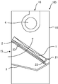
- FIG. 4 is a perspective view showing a state in which a filter is attached to the air conditioner according to the first embodiment of the present invention.
- the lower end of the heat exchanger 1 is fixed to the back side of the housing 10 via the fixing member 21.
- at least a gap S through which dust and the like can pass is provided between the fixing member 21 and the drain pan 3.
- the lower end of the heat exchanger 1 is supported by the fixing member 21 in the longitudinal direction, and is fixed to the fixing member 21 with screws or the like.
- the fixing member 21 is fixed to the back side of the housing 10 near both ends in the longitudinal direction of the fixing member 21. That is, the fixing member 21 is fixed by partially connecting the lower end portion of the heat exchanger 1 and the back surface side of the housing 10 while providing a gap S between the lower end portion of the heat exchanger 1 and the drain pan 3. It has a structure.
- the filter 2 is installed on the suction port 15 side of the heat exchanger 1 by the lower support members 22 attached to both ends in the longitudinal direction of the fixing member 21 and the upper support members 23 attached to both side surfaces of the heat exchanger 1. There is. Further, the filter 2 has a filter portion 2a for filtering the air passing through the heat exchanger 1 and a closing portion 2b for closing the gap S between the heat exchanger 1 and the drain pan 3.
- the filter unit 2a faces the heat exchanger 1 and filters dust, dust, dirt such as oil mist, or suspended matter in the air flowing to the heat exchanger 1.
- the closing portion 2b is provided so as to be connected to the lower portion of the filter portion 2a, and closes the gap S between the fixing member 21 supporting the lower end portion of the heat exchanger 1 and the drain pan 3 so that air does not pass through.
- the lower support member 22 is formed so as to extend in an L shape from both ends of the fixing member 21 in the longitudinal direction toward the suction port 15.
- the upper support member 23 is formed so as to extend in an L shape from both side surfaces above the center of the heat exchanger 1 to the suction port 15 side.
- the lower support member 22 and the upper support member 23 can support the filter 2 in a detachable manner by inserting the closing portion 2b of the filter 2 from above. Since the filter 2 is supported by the lower support member 22 located below the filter 2 and the upper support member 23 located above the filter 2, the filter 2 faces the heat exchanger 1 without sagging. Can be installed.
- the lower support member 22 and the upper support member 23 correspond to the "support member" in the present invention.
- the filter 2 With the filter 2 attached, the lower end of the closing portion 2b comes into contact with the surface of the drain pan 3, and the closing portion 2b closes the gap S between the heat exchanger 1 and the drain pan 3.
- the filter portion 2a when there is no closed portion 2b or when the filter portion 2a is configured up to the portion in contact with the surface of the drain pan 3, a part of the air taken in from the suction port 15 exchanges heat during the operation of the air conditioner 100.
- a short leak occurs that blows out into the air-conditioned space by passing through the gap S without passing through the vessel 1.
- the filter 2 is configured to have a filter portion 2a for filtering the air passing through the heat exchanger 1 and a closing portion 2b for closing the gap S between the heat exchanger 1 and the drain pan 3. ing.
- the boundary between the filter portion 2a and the closing portion 2b of the filter 2 is positioned so as to overlap the fixing member 21 that supports the heat exchanger 1 when the filter 2 is attached, thereby minimizing the air passing through the gap S. , The air passing through the heat exchanger 1 can be maximized. As a result, the taken-in air can be efficiently exchanged for heat.
- the closed portion 2b or at least the portion of the closed portion 2b in contact with the surface of the drain pan 3 with an elastic material, it is possible to prevent a gap from being formed between the closed portion 2b and the drain pan 3 and suppress a short leak. can do.
- FIG. 5 is a side explanatory view showing a state of the air conditioner according to the first embodiment of the present invention during operation.
- the blower 4 is driven with the filter 2 attached to take air into the air conditioner 100 from the suction port 15.
- the taken-in air passes through the filter portion 2a of the filter 2 and the heat exchanger 1 in order as shown by the arrow in FIG.
- the gap S between the heat exchanger 1 and the drain pan 3 is closed by the closing portion 2b of the filter 2, the air passing through the gap S can be suppressed. Therefore, the air taken in from the suction port 15 can be filtered by the filter 2 and heat exchanged by the heat exchanger 1 while suppressing the short leak from the gap S.
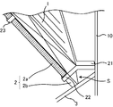
- FIG. 6 is a perspective view showing a state in which the filter is removed from the air conditioner according to the first embodiment of the present invention.
- FIG. 7 is a side explanatory view showing a state at the time of cleaning the air conditioner according to the first embodiment of the present invention.
- the washed-out dust or the like falls to the outlet 16 side, passes between the heat exchanger 1 and the back surface of the housing 10, and the gap S between the heat exchanger 1 and the drain pan 3, and the drain pan 3 on the suction port 15 side. Will be collected.
- By removing the filter 2 and cleaning it in this way it is possible to collect the dust and dirt washed out on the outlet 16 side to the drain pan 3 without staying in the middle.
- the upper panel 12 may also be removed and cleaning water may be sprayed on the heat exchanger 1 and other equipment from the upper side of the heat exchanger 1, that is, the outlet 16 side of the heat exchanger 1. Even in this case, the dust or the like washed out to the air outlet 16 side falls to the air outlet 16 side and passes through the gap S between the heat exchanger 1 and the back surface of the housing 10 and the heat exchanger 1 and the drain pan 3. It is collected in the drain pan 3 on the suction port 15 side.
- the housing 10 having the suction port 15 and the air outlet 16 and the space inside the housing 10 are provided on the suction port 15 side and the air outlet 16 side.
- the gap S can be closed by attaching the filter 2 during operation, and the gap S can be easily opened by removing the filter 2 during cleaning, so that the heat exchange rate during operation is reduced. Can be easily washed while suppressing the above.
- the fixing member 21 for connecting and fixing the lower end portion of the heat exchanger 1 to the housing 10 and the filter 2 are connected to the suction port 15 of the heat exchanger 1.
- a support member for installation on the side is further provided, and the support member is attached to at least one of the heat exchanger 1 and the fixing member 21.
- the support members are a lower support member 22 attached to both ends in the longitudinal direction of the fixing member 21 and an upper support attached to both side surfaces of the heat exchanger 1.
- the member 23 is included, and the lower support member 22 and the upper support member 23 are L-shaped.
- the filter 2 is supported by the lower support member 22 located below the filter 2 and the upper support member 23 located above the filter 2, so that the filter 2 does not hang down and the filter 2 is heat exchangerd. It can be installed facing 1.
- the boundary between the filter portion 2a and the closing portion 2b of the filter 2 is at a position where it overlaps with the fixing member 21 when the filter 2 is attached.
- the air passing through the gap S can be minimized and the air passing through the heat exchanger 1 can be maximized, so that the taken-in air can be efficiently exchanged with heat.
- At least a portion of the closing portion 2b in contact with the drain pan 3 is formed of an elastic material.
- the air conditioner 100 further includes a blower 4 installed on the air outlet 16 side of the heat exchanger 1 and above the housing 10.
- FIG. 8 is a schematic cross-sectional view of the air conditioner according to the second embodiment of the present invention as viewed from the side.
- FIG. 9 is a perspective view showing a state in which a filter is attached to the air conditioner according to the second embodiment of the present invention.
- FIG. 10 is a perspective view showing a state in which the filter is removed from the air conditioner according to the second embodiment of the present invention.
- the air conditioner 200 according to the second embodiment is different from the air conditioner 100 according to the first embodiment in that the support member is composed of the rail type support member 24.
- the same parts as the air conditioner 100 according to the first embodiment are designated by the same reference numerals and the description is omitted, and the air conditioner according to the first embodiment is omitted.
- the difference from 100 will be mainly described.
- the rail-type support member 24 is formed so as to extend in an L shape toward the suction port 15 over half or more of both side surface portions of the heat exchanger 1. ..
- the rail type support member 24 can be detachably attached to the filter 2 by inserting the closing portion 2b of the filter 2 from above.
- the filter 2 is installed facing the heat exchanger 1 without sagging. Since the rail type support member 24 functions as a guide when the filter 2 is attached, the filter 2 can be easily attached.
- the rail type support member 24 corresponds to the "support member" in the present invention.
- the air conditioner 200 according to the second embodiment is composed of an L-shaped rail-shaped support member 24 attached over half or more of both side surface portions of the heat exchanger 1.
- the filter 2 can be installed facing the heat exchanger 1 without the filter 2 hanging down, but also the rail type support member 24 functions as a guide when the filter 2 is attached. , It becomes easy to attach the filter 2.
- the fixing member 21 has a structure in which the fixing member 21 is connected and fixed at two points on the back surface side of the housing 10 and near both ends, but is washed out to the air outlet 16 side of the heat exchanger 1 at the time of cleaning. Any structure may be used as long as the collected dust or the like is collected in the drain pan 3 on the suction port 15 side through the gap S between the heat exchanger 1 and the back surface of the housing 10 and between the heat exchanger 1 and the drain pan 3.
- the filter 2 is supported by two points, the lower support member 22 and the upper support member 23, but a plurality of upper support members 23 attached to both side surfaces of the heat exchanger 1 are provided. Therefore, a structure that supports the filter 2 more firmly may be used.
Landscapes
- Engineering & Computer Science (AREA)
- Chemical & Material Sciences (AREA)
- Combustion & Propulsion (AREA)
- Mechanical Engineering (AREA)
- General Engineering & Computer Science (AREA)
- Physics & Mathematics (AREA)
- Thermal Sciences (AREA)
- Devices For Blowing Cold Air, Devices For Blowing Warm Air, And Means For Preventing Water Condensation In Air Conditioning Units (AREA)
Abstract
空気調和装置100は、吸込口15と吹出口16を有する筐体10と、筐体10内の空間を吸込口15側と吹出口16側に区分するように設置された熱交換器1と、熱交換器1の下端部と隙間Sを設けて熱交換器1の下方に設置され、結露水や洗浄水を回収するドレンパン3と、熱交換器1を通過する空気を濾過するフィルタ部2aと、熱交換器1とドレンパン3の隙間Sを塞ぐ閉塞部2bを有する着脱可能なフィルタ2と、を備えている。
Description
本発明は、空気調和装置に関し、特に吸い込んだ空気をフィルタにより濾過することが可能な空気調和装置に関するものである。
空気調和装置においては、空気の吸込口にフィルタが配置され、当該フィルタによって空気調和装置の内部へと吸い込まれた空気の濾過が行われることが多い。これにより、空気調和装置の内部に汚れが蓄積されることを抑制することができる。しかし、機械工場や食品工場等に設置された場合、空気中に含まれたごみ、粉塵、またはオイルミスト等の汚れがフィルタを通過して空気調和装置の内部に蓄積することも少なくなかった。そのため、空気調和装置の内部の洗浄を可能とした空気調和装置が提案されている(例えば、特許文献1参照)。
特許文献1の空調用室内機では、本体ケーシングの背板と熱交換器の下端部との間に、ごみが通過可能な隙間と、この隙間を開閉可能とする仕切り部材とが設けられている。こうすることにより、室内機の運転中は隙間を仕切り部材により閉鎖することで熱交換器の上流側空間と下流側空間とが短絡しないようにすることができ、洗浄を行う際は仕切り部材を取り外して隙間を開放することでごみを回収することができる。
しかしながら、隙間を開閉可能とする仕切り部材は作業者が本体ケーシング内にアクセスする前面側から離れている位置に設けられているため、仕切り部材を固定するネジ部材を着脱する際に無理な体勢となり、作業性が悪かった。
しかしながら、隙間を開閉可能とする仕切り部材は作業者が本体ケーシング内にアクセスする前面側から離れている位置に設けられているため、仕切り部材を固定するネジ部材を着脱する際に無理な体勢となり、作業性が悪かった。
本発明は、上述のような問題を解決するためになされたものであり、運転時には熱交換器の下端部とドレンパンとの隙間を塞ぐ状態にし、洗浄時には容易に隙間を開放した状態にできる空気調和装置を提供することを目的とする。
本発明における空気調和装置は、吸込口と吹出口を有する筐体と、筐体内の空間を吸込口側と吹出口側に区分するように設置された熱交換器と、熱交換器の下端部と隙間を設けて熱交換器の下方に設置され、結露水や洗浄水を回収するドレンパンと、熱交換器を通過する空気を濾過するフィルタ部と、熱交換器とドレンパンの隙間を塞ぐ閉塞部を有する着脱可能なフィルタと、を備えるものである。
本発明における空気調和装置によれば、運転時には隙間を塞いだ状態にし、洗浄時には容易に隙間を開放した状態にできるため、運転時の熱交換率の低下を抑制しつつ、洗浄を容易に行うことができる。
以下、本発明の実施の形態に係る空気調和装置について図面等を参照しながら説明する。なお、各図中、同一または相当する部分には、同一符号を付して、その説明を適宜省略または簡略化する。また、各図に記載の構成について、その形状、大きさ及び配置等は、この発明の範囲内で適宜変更することができる。
実施の形態1.
図1は、実施の形態1に係る空気調和装置の外観を示す斜視図である。実施の形態の空気調和装置100は、その外形を形成する筐体10の内部に、後述する種々の構成部品を収容している。また空気調和装置100の前面側には、複数のスリットが形成された中パネル11と、中パネル11の上方に設けられた上パネル12と、中パネル11の下方に設けられた下パネル13が取り付けられている。中パネル11、上パネル12、及び下パネル13は取り外し可能である。中パネル11に形成された複数のスリットは、空調対象空間の空気を吸い込むための吸込口15として機能している。また筐体10の上部には、吸込口15から吸い込んで内部で空調した空気を空調対象空間に吹き出す吹出口16が設けられている。
図1は、実施の形態1に係る空気調和装置の外観を示す斜視図である。実施の形態の空気調和装置100は、その外形を形成する筐体10の内部に、後述する種々の構成部品を収容している。また空気調和装置100の前面側には、複数のスリットが形成された中パネル11と、中パネル11の上方に設けられた上パネル12と、中パネル11の下方に設けられた下パネル13が取り付けられている。中パネル11、上パネル12、及び下パネル13は取り外し可能である。中パネル11に形成された複数のスリットは、空調対象空間の空気を吸い込むための吸込口15として機能している。また筐体10の上部には、吸込口15から吸い込んで内部で空調した空気を空調対象空間に吹き出す吹出口16が設けられている。
図2は、実施の形態1に係る空気調和装置の内部構成を示す斜視図である。図3は、実施の形態1に係る空気調和装置を側面から見た概略断面図である。図2に示す空気調和装置100は、図1に示す空気調和装置100から中パネル11、上パネル12、及び下パネル13を取り外した状態である。空気調和装置100は、筐体10の内部に、熱交換器1、フィルタ2、ドレンパン3、送風機4、モータ5、及び制御箱6等を備える。
熱交換器1は、吸込口15から取り込まれた空気と熱交換するものであり、図示しない圧縮機、四方弁、室外熱交換器、膨張弁等と共に冷凍サイクルを構成する。少なくとも冷凍サイクルの圧縮機及び室外熱交換器は、室外熱交換器に外気を送風する室外送風機と共に、室外機に搭載されている。冷房運転時には、熱交換器1は蒸発器として機能し、熱交換器1を通過する空気は冷媒との熱交換により冷却される。一方、暖房運転時には、熱交換器1は凝縮器として機能し、熱交換器1を通過する空気は冷媒との熱交換により加熱される。熱交換器1は、図3に示すように背面から前面に向かうにしたがって斜め上方に傾斜するように配置されており、筐体10内の空間を吸込口15側と吹出口16側に区分するように設置されている。熱交換器1は、例えばフィンチューブ型の熱交換器である。
フィルタ2は、熱交換器1よりも吸込口15側に設置され、吸込口15から空気調和装置100内へと吸い込まれた空気中のゴミ、粉塵、またはオイルミスト等の汚れまたは浮遊物等を濾過するものである。フィルタ2は、後述する支持部材によって熱交換器1の吸込口15側に設置されている。ドレンパン3は、熱交換器1の下方に配置され、熱交換器1で生じた結露水や洗浄時の洗浄水を熱交換器1の吸込口15側に回収するものである。吸込口15側に回収された結露水や洗浄水は排水口3aから筐体10の外に排出される。
送風機4は、図3の矢印が示すように吸込口15から吹出口16に向かって空気の流れを形成するものであり、モータ5により回転駆動され、空気の流れを生み出す。送風機4及びモータ5は、熱交換器1の吹出口16側かつ筐体10内の上部に配置されている。送風機4は、例えば、シロッコファンまたはターボファン等である。
制御箱6は、モータ5の出力周波数を制御して、送風機4の風量を制御する制御装置を備えるものである。制御箱6は、ドレンパン3の下方に配置されている。
図4は、本発明の実施の形態1に係る空気調和装置にフィルタを取り付けた状態を示す斜視図である。熱交換器1の下端部は固定部材21を介して筐体10の背面側に固定されている。ここで固定部材21とドレンパン3との間には、少なくともゴミなどが通過可能な隙間Sが設けられている。具体的には、熱交換器1の下端部は、長手方向に固定部材21に支持されており、ネジなどで固定部材21に固定されている。さらに固定部材21は、固定部材21の長手方向両端部付近で筐体10の背面側と固定されている。つまり、固定部材21は、熱交換器1の下端部とドレンパン3との間に隙間Sを設けつつ、熱交換器1の下端部と筐体10の背面側を部分的に連結して固定する構成を有するものである。
フィルタ2は、固定部材21の長手方向両端部に取り付けられた下部支持部材22と熱交換器1の両側面部に取り付けられた上部支持部材23によって熱交換器1の吸込口15側に設置されている。またフィルタ2は、熱交換器1を通過する空気を濾過するフィルタ部2aと、熱交換器1とドレンパン3との隙間Sを塞ぐ閉塞部2bを有する。フィルタ部2aは、熱交換器1と対面しており、熱交換器1へ流動する空気中のゴミ、粉塵、またはオイルミスト等の汚れまたは浮遊物等を濾過する。閉塞部2bは、フィルタ部2aの下部に連結して設けられており、熱交換器1の下端部を支持する固定部材21とドレンパン3の隙間Sを空気が通過しないように塞いでいる。
下部支持部材22は、固定部材21の長手方向両端部から吸込口15側にL字形状に延びて形成されている。上部支持部材23は、熱交換器1の真ん中より上方の両側面部から吸込口15側にL字形状に延びて形成されている。下部支持部材22及び上部支持部材23は、フィルタ2の閉塞部2bが上側から差し込まれることで、フィルタ2を着脱可能に支持することができる。このようにフィルタ2の下方に位置する下部支持部材22とフィルタ2の上方に位置する上部支持部材23によりフィルタ2を支持するため、フィルタ2が垂れることなく、フィルタ2を熱交換器1と対面して設置することができる。なお、下部支持部材22及び上部支持部材23は、本発明における「支持部材」に対応する。
フィルタ2を取り付けた状態において、閉塞部2bの下端部がドレンパン3の表面と接し、閉塞部2bが熱交換器1とドレンパン3の隙間Sを覆うように塞ぐ。ここで、閉塞部2bがない場合あるいはドレンパン3の表面と接する部分までフィルタ部2aで構成されていた場合、空気調和装置100の運転中において、吸込口15から取り込んだ空気の一部が熱交換器1を通過せずに隙間Sを通過して空調対象空間に吹き出すショートリークが起きてしまう。このとき、隙間Sを通過した空気は熱交換が行われないため、熱交換率の低下を招いてしまう。この課題を解決するために、フィルタ2は、熱交換器1を通過する空気を濾過するフィルタ部2aと、熱交換器1とドレンパン3との隙間Sを塞ぐ閉塞部2bを有して構成されている。
なお、フィルタ2のフィルタ部2aと閉塞部2bの境目を、フィルタ2を取り付けた際に熱交換器1を支持する固定部材21と重なる位置にすることで隙間Sを通過する空気を最小限にし、熱交換器1を通過する空気を最大限にすることができる。この結果、取り込んだ空気を効率よく熱交換することができる。
また閉塞部2bあるいは閉塞部2bの少なくともドレンパン3の表面と接する部分を弾性素材で形成することで、閉塞部2bとドレンパン3との間に隙間を生じさせにくくすることができ、ショートリークを抑制することができる。
次に、実施の形態1に係る空気調和装置100の運転時の様子について説明する。図5は、本発明の実施の形態1に係る空気調和装置の運転時の様子を示す側面説明図である。空気調和装置100の運転時では、フィルタ2が取り付けられた状態で送風機4を駆動させて吸込口15から空気を空気調和装置100内に取り込む。取り込まれた空気は図5の矢印が示すようにフィルタ2のフィルタ部2aと熱交換器1を順に通過する。また、熱交換器1とドレンパン3の隙間Sはフィルタ2の閉塞部2bによって塞がれているため、隙間Sを通過する空気を抑制することができる。したがって、隙間Sからのショートリークを抑制しつつ、吸込口15から取り込んだ空気をフィルタ2で濾過し、熱交換器1で熱交換することができる。
次に、実施の形態1に係る空気調和装置100の洗浄時の様子について説明する。図6は、本発明の実施の形態1に係る空気調和装置からフィルタを取り外した状態を示す斜視図である。図7は、本発明の実施の形態1に係る空気調和装置の洗浄時の様子を示す側面説明図である。空気調和装置100の内部を洗浄する際には、まず空気調和装置100を運転停止状態にして中パネル11を取り外す。そして、空気調和装置100の前面側からフィルタ2を上側に引き抜いて取り外す。フィルタ2を取り外した状態で吸込口15側から熱交換器1に洗浄水を吹き付けることで、熱交換器1に付着していたごみや汚れが吹出口16側に洗い出される。洗い出されたごみ等は吹出口16側に落下し、熱交換器1と筐体10の背面との間と熱交換器1とドレンパン3との隙間Sを通って吸込口15側のドレンパン3に回収される。このようにフィルタ2を取り外して洗浄することで、吹出口16側に洗い出されたごみや汚れ等を途中で滞留させることなく、ドレンパン3へ回収することができる。
また、洗浄するときは上パネル12も取り外して熱交換器1の上側、つまり熱交換器1の吹出口16側から熱交換器1やその他の機器に洗浄水を吹き付けても良い。この場合でも吹出口16側に洗い出されたごみ等は吹出口16側に落下し、熱交換器1と筐体10の背面との間と熱交換器1とドレンパン3との隙間Sを通って吸込口15側のドレンパン3に回収される。
以上説明したように、本実施の形態1に係る空気調和装置100は、吸込口15と吹出口16を有する筐体10と、筐体10内の空間を吸込口15側と吹出口16側に区分するように設置された熱交換器1と、熱交換器1の下端部と隙間Sを設けて熱交換器1の下方に設置され、結露水や洗浄水を回収するドレンパン3と、熱交換器1を通過する空気を濾過するフィルタ部2aと、熱交換器1とドレンパン3の隙間Sを塞ぐ閉塞部2bを有する着脱可能なフィルタ2と、を備えている。
この構成によれば、運転時にはフィルタ2を取り付けることで隙間Sを塞いだ状態にし、洗浄時にはフィルタ2を取り外すことで容易に隙間Sを開放した状態にできるため、運転時の熱交換率の低下を抑制しつつ、洗浄を容易に行うことができる。
さらに、本実施の形態1に係る空気調和装置100において、熱交換器1の下端部を筐体10と連結して固定するための固定部材21と、フィルタ2を熱交換器1の吸込口15側に設置するための支持部材と、をさらに備え、支持部材は、熱交換器1と固定部材21の少なくとも一方に取り付けられている。
この構成によれば、運転時には熱交換器1を通過するほとんどの空気を濾過でき、さらに洗浄時にフィルタ2を容易に取り外しやすくなる。
さらに、本実施の形態1に係る空気調和装置100において、支持部材は、固定部材21の長手方向両端部に取り付けられた下部支持部材22と、熱交換器1の両側面部に取り付けられた上部支持部材23を含んで構成され、下部支持部材22及び上部支持部材23はL字形状である。
この構成によれば、フィルタ2の下方に位置する下部支持部材22とフィルタ2の上方に位置する上部支持部材23によりフィルタ2を支持するため、フィルタ2が垂れることなく、フィルタ2を熱交換器1と対面して設置することができる。
さらに、本実施の形態1に係る空気調和装置100において、フィルタ2のフィルタ部2aと閉塞部2bの境目が、フィルタ2を取り付けた際に固定部材21と重なる位置となる。
この構成によれば、隙間Sを通過する空気を最小限にし、熱交換器1を通過する空気を最大限にすることができるため、取り込んだ空気を効率よく熱交換することができる。
さらに、本実施の形態1に係る空気調和装置100において、閉塞部2bの少なくともドレンパン3と接する部分は、弾性素材から形成されている。
この構成によれば、閉塞部2bとドレンパン3との間に隙間を生じさせにくくすることができ、ショートリークを抑制することができる。
本実施の形態に係る空気調和装置100において、熱交換器1の吹出口16側かつ、筐体10の上部に設置された送風機4をさらに備えている。
この構成によれば、運転時にはフィルタ2を通過した空気を吸い込むため、送風機4の内部が汚れることを抑制でき、さらに洗浄時には洗浄水が送風機4及びモータ5にかかることを防止できる。
実施の形態2.
本発明の実施の形態2における空気調和装置について説明する。図8は、本発明の実施の形態2に係る空気調和装置を側面から見た概略断面図である。図9は、本発明の実施の形態2に係る空気調和装置にフィルタを取り付けた状態を示す斜視図である。図10は、本発明の実施の形態2に係る空気調和装置からフィルタを取り外した状態を示す斜視図である。実施の形態2における空気調和装置200は、支持部材がレール型支持部材24から構成されている点で、実施の形態1における空気調和装置100と相違する。実施の形態2に係る空気調和装置200の説明では、実施の形態1に係る空気調和装置100と同一の部分は同一の符号を付して説明を省略し、実施の形態1に係る空気調和装置100との相違点を中心に説明する。
本発明の実施の形態2における空気調和装置について説明する。図8は、本発明の実施の形態2に係る空気調和装置を側面から見た概略断面図である。図9は、本発明の実施の形態2に係る空気調和装置にフィルタを取り付けた状態を示す斜視図である。図10は、本発明の実施の形態2に係る空気調和装置からフィルタを取り外した状態を示す斜視図である。実施の形態2における空気調和装置200は、支持部材がレール型支持部材24から構成されている点で、実施の形態1における空気調和装置100と相違する。実施の形態2に係る空気調和装置200の説明では、実施の形態1に係る空気調和装置100と同一の部分は同一の符号を付して説明を省略し、実施の形態1に係る空気調和装置100との相違点を中心に説明する。
実施の形態2におけるレール型支持部材24は、図8、図9及び図10に示すように熱交換器1の両側面部の半分以上にわたって吸込口15側にL字形状に延びて形成されている。レール型支持部材24は、フィルタ2の閉塞部2bが上側から差し込まれることで、フィルタ2を着脱可能に取り付けることができる。このように熱交換器1の両側面部の半分以上にわたって取り付けられたレール型支持部材24によりフィルタ2を支持することで、フィルタ2が垂れることなく、フィルタ2を熱交換器1と対面して設置することができるだけでなく、フィルタ2を取り付ける際にレール型支持部材24がガイドの機能を果たすため、フィルタ2を取り付けやすくなる。なお、レール型支持部材24は、本発明における「支持部材」に対応する。
以上説明したように、本実施の形態2に係る空気調和装置200は、熱交換器1の両側面部の半分以上にわたって取り付けられたL字形状のレール型支持部材24から構成されている。
この構成によれば、フィルタ2が垂れることなく、フィルタ2を熱交換器1と対面して設置することができるだけでなく、フィルタ2を取り付ける際にレール型支持部材24がガイドの機能を果たすため、フィルタ2を取り付けやすくなる。
以上、本発明を、上記実施の形態を用いて説明したが、本発明の技術的範囲は上記実施の形態に記載の範囲には限定されない。発明の要旨を逸脱しない範囲で上記各実施の形態に多様な変更又は改良を加えることができ、該変更又は改良を加えた形態も本発明の技術的範囲に含まれる。
例えば、本実施の形態では、固定部材21は筐体10の背面側と両端部付近の2点で連結して固定する構造としたが、洗浄時に熱交換器1の吹出口16側に洗い出されたごみ等が熱交換器1と筐体10の背面との間と熱交換器1とドレンパン3との隙間Sを通って吸込口15側のドレンパン3に回収される構造であれば良い。
例えば、本実施の形態1では、下部支持部材22と上部支持部材23の2点によりフィルタ2を支持する構造としたが、熱交換器1の両側面部に取り付けられた上部支持部材23を複数設けることで、より堅固にフィルタ2を支持する構造としても良い。
1 熱交換器、2 フィルタ、2a 、2b 、3 ドレンパン、3a 排水口、4 送風機、5 モータ、6 制御箱、10 筐体、11 中パネル、12 上パネル、13 下パネル、15 吸込口、16 吹出口、21 固定部材、22 下部支持部材、23 上部支持部材、24 レール型支持部材、100、200 空気調和装置、S 隙間
Claims (7)
- 吸込口と吹出口を有する筐体と、
前記筐体内の空間を前記吸込口側と前記吹出口側に区分するように設置された熱交換器と、
前記熱交換器の下端部と隙間を設けて前記熱交換器の下方に設置され、結露水や洗浄水を回収するドレンパンと、
前記熱交換器を通過する空気を濾過するフィルタ部と、前記熱交換器と前記ドレンパンの前記隙間を塞ぐ閉塞部を有する着脱可能なフィルタと、
を備える空気調和装置。 - 前記熱交換器の下端部を前記筐体と連結して固定するための固定部材と、
前記フィルタを前記熱交換器の前記吸込口側に設置するための支持部材と、をさらに備え、
前記支持部材は、前記熱交換器と前記固定部材の少なくとも一方に取り付けられている請求項1に記載の空気調和装置。 - 前記支持部材は、前記固定部材の長手方向両端部に取り付けられた下部支持部材と、前記熱交換器の両側面部に取り付けられた上部支持部材を含んで構成され、
前記下部支持部材及び前記上部支持部材はL字形状である請求項2に記載の空気調和装置。 - 前記支持部材は、前記熱交換器の両側面部の半分以上にわたって取り付けられたL字形状のレール型支持部材から構成される請求項2に記載の空気調和装置。
- 前記フィルタの前記フィルタ部と前記閉塞部の境目が、前記フィルタを取り付けた際に前記固定部材と重なる位置となる請求項2~4の何れか一項に記載の空気調和装置。
- 前記閉塞部の少なくとも前記ドレンパンと接する部分は、弾性素材から形成される請求項1~5の何れか一項に記載の空気調和装置。
- 前記熱交換器の前記吹出口側かつ、前記筐体の上部に設置された送風機をさらに備えた請求項1~6の何れか一項に記載の空気調和装置。
Priority Applications (2)
| Application Number | Priority Date | Filing Date | Title |
|---|---|---|---|
| JP2022502354A JPWO2021171348A1 (ja) | 2020-02-25 | 2020-02-25 | |
| PCT/JP2020/007406 WO2021171348A1 (ja) | 2020-02-25 | 2020-02-25 | 空気調和装置 |
Applications Claiming Priority (1)
| Application Number | Priority Date | Filing Date | Title |
|---|---|---|---|
| PCT/JP2020/007406 WO2021171348A1 (ja) | 2020-02-25 | 2020-02-25 | 空気調和装置 |
Publications (1)
| Publication Number | Publication Date |
|---|---|
| WO2021171348A1 true WO2021171348A1 (ja) | 2021-09-02 |
Family
ID=77492049
Family Applications (1)
| Application Number | Title | Priority Date | Filing Date |
|---|---|---|---|
| PCT/JP2020/007406 WO2021171348A1 (ja) | 2020-02-25 | 2020-02-25 | 空気調和装置 |
Country Status (2)
| Country | Link |
|---|---|
| JP (1) | JPWO2021171348A1 (ja) |
| WO (1) | WO2021171348A1 (ja) |
Citations (4)
| Publication number | Priority date | Publication date | Assignee | Title |
|---|---|---|---|---|
| JPH0178820U (ja) * | 1987-11-11 | 1989-05-26 | ||
| JP2001263786A (ja) * | 2000-03-17 | 2001-09-26 | Fujitsu General Ltd | 空気調和機 |
| JP2011106715A (ja) * | 2009-11-16 | 2011-06-02 | Mitsubishi Electric Corp | 空調用室内機 |
| JP2019217434A (ja) * | 2018-06-18 | 2019-12-26 | ニッタ株式会社 | エアフィルタ装置 |
Family Cites Families (1)
| Publication number | Priority date | Publication date | Assignee | Title |
|---|---|---|---|---|
| JPS58194393U (ja) * | 1982-06-15 | 1983-12-24 | 三洋電機株式会社 | 熱交換ユニツト |
-
2020
- 2020-02-25 JP JP2022502354A patent/JPWO2021171348A1/ja active Pending
- 2020-02-25 WO PCT/JP2020/007406 patent/WO2021171348A1/ja active Application Filing
Patent Citations (4)
| Publication number | Priority date | Publication date | Assignee | Title |
|---|---|---|---|---|
| JPH0178820U (ja) * | 1987-11-11 | 1989-05-26 | ||
| JP2001263786A (ja) * | 2000-03-17 | 2001-09-26 | Fujitsu General Ltd | 空気調和機 |
| JP2011106715A (ja) * | 2009-11-16 | 2011-06-02 | Mitsubishi Electric Corp | 空調用室内機 |
| JP2019217434A (ja) * | 2018-06-18 | 2019-12-26 | ニッタ株式会社 | エアフィルタ装置 |
Also Published As
| Publication number | Publication date |
|---|---|
| JPWO2021171348A1 (ja) | 2021-09-02 |
Similar Documents
| Publication | Publication Date | Title |
|---|---|---|
| AU2008336991B2 (en) | Indoor unit of air conditioner | |
| JPH11226331A (ja) | 空気調和装置の室内機 | |
| EP2233853A1 (en) | Indoor unit for air conditioner | |
| EP1780473B1 (en) | Air conditioner | |
| WO2021171348A1 (ja) | 空気調和装置 | |
| WO2009028766A2 (en) | Air conditioner | |
| JP2004020151A (ja) | 空気調和機 | |
| JP5999944B2 (ja) | 空調室内機 | |
| JP2008196715A (ja) | 空気調和装置 | |
| JP2016130615A (ja) | 空気調和機 | |
| KR20060081171A (ko) | 공기조화기 | |
| KR200245703Y1 (ko) | 패키지에어컨의실내기 | |
| KR100548985B1 (ko) | 에어필터의 회동 장착구조를 갖는 에어컨 | |
| JP3111882B2 (ja) | 天井設置型空気調和装置 | |
| WO2023238183A1 (ja) | 除湿機 | |
| KR20040026076A (ko) | 공기조화기 실내기 | |
| KR100654727B1 (ko) | 필터프레임이 결합된 에어컨 흡입부 구조 | |
| KR101186846B1 (ko) | 필터 탈 장착이 용이한 공기조화기 | |
| JP2010117104A (ja) | 空調機 | |
| JP2013245851A (ja) | 空調用室内機 | |
| JP7007602B2 (ja) | 空気調和システム | |
| KR20070069537A (ko) | 공기 조화기 | |
| KR101162168B1 (ko) | 공기조화기의 실내기 | |
| KR20070069538A (ko) | 공기 조화기 | |
| KR20100025341A (ko) | 공기조화기의 실내기 |
Legal Events
| Date | Code | Title | Description |
|---|---|---|---|
| 121 | Ep: the epo has been informed by wipo that ep was designated in this application |
Ref document number: 20921844 Country of ref document: EP Kind code of ref document: A1 |
|
| ENP | Entry into the national phase |
Ref document number: 2022502354 Country of ref document: JP Kind code of ref document: A |
|
| NENP | Non-entry into the national phase |
Ref country code: DE |
|
| 122 | Ep: pct application non-entry in european phase |
Ref document number: 20921844 Country of ref document: EP Kind code of ref document: A1 |