WO2023223804A1 - パワーモジュール、パワーモジュールの製造方法、および電力変換装置 - Google Patents
パワーモジュール、パワーモジュールの製造方法、および電力変換装置 Download PDFInfo
- Publication number
- WO2023223804A1 WO2023223804A1 PCT/JP2023/016649 JP2023016649W WO2023223804A1 WO 2023223804 A1 WO2023223804 A1 WO 2023223804A1 JP 2023016649 W JP2023016649 W JP 2023016649W WO 2023223804 A1 WO2023223804 A1 WO 2023223804A1
- Authority
- WO
- WIPO (PCT)
- Prior art keywords
- main
- terminal
- power module
- main terminal
- heat sink
- Prior art date
- Legal status (The legal status is an assumption and is not a legal conclusion. Google has not performed a legal analysis and makes no representation as to the accuracy of the status listed.)
- Ceased
Links
Images













Classifications
-
- H—ELECTRICITY
- H10—SEMICONDUCTOR DEVICES; ELECTRIC SOLID-STATE DEVICES NOT OTHERWISE PROVIDED FOR
- H10W—GENERIC PACKAGES, INTERCONNECTIONS, CONNECTORS OR OTHER CONSTRUCTIONAL DETAILS OF DEVICES COVERED BY CLASS H10
- H10W40/00—Arrangements for thermal protection or thermal control
- H10W40/01—Manufacture or treatment
- H10W40/03—Manufacture or treatment of arrangements for cooling
- H10W40/037—Assembling together parts thereof
-
- H—ELECTRICITY
- H10—SEMICONDUCTOR DEVICES; ELECTRIC SOLID-STATE DEVICES NOT OTHERWISE PROVIDED FOR
- H10W—GENERIC PACKAGES, INTERCONNECTIONS, CONNECTORS OR OTHER CONSTRUCTIONAL DETAILS OF DEVICES COVERED BY CLASS H10
- H10W40/00—Arrangements for thermal protection or thermal control
- H10W40/20—Arrangements for cooling
- H10W40/22—Arrangements for cooling characterised by their shape, e.g. having conical or cylindrical projections
- H10W40/226—Arrangements for cooling characterised by their shape, e.g. having conical or cylindrical projections characterised by projecting parts, e.g. fins to increase surface area
-
- H—ELECTRICITY
- H10—SEMICONDUCTOR DEVICES; ELECTRIC SOLID-STATE DEVICES NOT OTHERWISE PROVIDED FOR
- H10W—GENERIC PACKAGES, INTERCONNECTIONS, CONNECTORS OR OTHER CONSTRUCTIONAL DETAILS OF DEVICES COVERED BY CLASS H10
- H10W40/00—Arrangements for thermal protection or thermal control
- H10W40/60—Securing means for detachable heating or cooling arrangements, e.g. clamps
- H10W40/611—Bolts or screws
-
- H—ELECTRICITY
- H10—SEMICONDUCTOR DEVICES; ELECTRIC SOLID-STATE DEVICES NOT OTHERWISE PROVIDED FOR
- H10W—GENERIC PACKAGES, INTERCONNECTIONS, CONNECTORS OR OTHER CONSTRUCTIONAL DETAILS OF DEVICES COVERED BY CLASS H10
- H10W90/00—Package configurations
-
- H—ELECTRICITY
- H10—SEMICONDUCTOR DEVICES; ELECTRIC SOLID-STATE DEVICES NOT OTHERWISE PROVIDED FOR
- H10W—GENERIC PACKAGES, INTERCONNECTIONS, CONNECTORS OR OTHER CONSTRUCTIONAL DETAILS OF DEVICES COVERED BY CLASS H10
- H10W74/00—Encapsulations, e.g. protective coatings
- H10W74/10—Encapsulations, e.g. protective coatings characterised by their shape or disposition
- H10W74/111—Encapsulations, e.g. protective coatings characterised by their shape or disposition the semiconductor body being completely enclosed
Definitions
- the present disclosure relates to a power module, a method for manufacturing a power module, and a power conversion device.
- Patent Document 1 discloses a heat sink integrated power module that includes a power module part, a fin base, and a heat radiation fin.
- the power module section includes a module base, a power semiconductor element mounted on the module base, and a mold resin that seals the power semiconductor element.
- the fin base includes a heat dissipating portion to which the heat dissipating fin is attached, and a base portion formed in the heat dissipating portion and to which the module base is joined.
- the module base is provided with a first uneven portion, and the base portion is provided with a second uneven portion that fits into the first uneven portion.
- Patent Document 1 since the technology described in Patent Document 1 does not have a structure for connecting the bus bar to the main terminal, there was a concern that the temperature of the main terminal would increase.
- an object of the present disclosure is to provide a technology that can suppress the temperature rise of the main terminal by connecting an external terminal to the main terminal in a heat sink integrated power module.
- a power module includes a semiconductor element, a frame on which the semiconductor element is mounted on one side, a module base on which the frame is placed on one side, a main terminal that is a part of the frame, and a frame on which the semiconductor element is mounted on one side. a mold part that seals the semiconductor element, the frame, and the module base so that the main terminals are exposed; a base part that is integrated with the other surface of the module base exposed from the mold part; a heat sink having a plurality of heat dissipation fins protruding on the side opposite to the module base in the section; and an external heat sink connected to the first main surface of the main terminal or the second main surface opposite to the first main surface.
- terminal forming processing is not required on the first main surface and the second main surface of the main terminal, so the areas of the first main surface and the second main surface can be increased. This allows the external terminal to be connected to the main terminal in the heat sink-integrated power module, thereby making it possible to suppress a rise in temperature of the main terminal.
- FIG. 2 is a cross-sectional view of the power module according to the first embodiment.
- FIG. 2 is a top view of the power module according to the first embodiment.
- FIG. 3 is a top view of a power module according to a modification of the first embodiment.
- FIG. 3 is a cross-sectional view showing a connection between a main terminal and a bus bar included in a power module according to a modification of the first embodiment.
- FIG. 3 is a top view of a power module according to a modification of the first embodiment.
- FIG. 3 is a top view of a power module according to a modification of the first embodiment.
- FIG. 3 is a top view of a power module according to a modification of the first embodiment.
- FIG. 7 is a cross-sectional view showing a connection between a main terminal and a bus bar provided in a power module according to a modification of the first embodiment by screw fastening.
- FIG. 7 is a top view showing a connection between a main terminal and a bus bar provided in the power module according to a modification of the first embodiment by screw fastening.
- FIG. 7 is a sectional view showing a connection by screw fastening between a main terminal and a bus bar with a nut provided in a power module according to a modification of the first embodiment.
- FIG. 7 is a cross-sectional view showing a connection between a main terminal with a nut and a bus bar by screw fastening, which the power module according to a modification of the first embodiment includes.
- FIG. 7 is a cross-sectional view showing a connection by screw fastening between a main terminal and a bus bar in which a screw fastening auxiliary member is provided in a power module according to a modification of the first embodiment.
- FIG. 7 is a cross-sectional view showing the positional relationship between the main terminal and the screw fastening auxiliary member included in the power module according to the modification of the first embodiment.
- FIG. 7 is a cross-sectional view showing the positional relationship between a main terminal and an auxiliary screw fastening member with an elastic function included in the power module according to a modification of the first embodiment.
- FIG. 7 is a cross-sectional view showing a solder connection between a main terminal and a bus bar included in a power module according to a modification of the first embodiment.
- FIG. 3 is a cross-sectional view showing a welded connection between a main terminal and a bus bar included in a power module according to a modification of the first embodiment.
- FIG. 7 is a cross-sectional view showing a connection by crimp between a main terminal and a bus bar included in a power module according to a modification of the first embodiment.
- FIG. 3 is a cross-sectional view of a power module according to a modification of the first embodiment.
- FIG. 3 is a cross-sectional view of a power module according to a modification of the first embodiment.
- FIG. 3 is a cross-sectional view of a power module according to a modification of the first embodiment.
- FIG. 3 is a cross-sectional view of a power module according to a second embodiment.
- FIG. 1 is a cross-sectional view showing a welded connection between a main terminal and a bus bar included in a power module according to a modification of the first embodiment.
- FIG. 7 is a cross-
- FIG. 7 is a cross-sectional view showing a connection by screw fastening between a terminal block and a heat sink included in the power module according to Embodiment 2;
- FIG. 7 is a cross-sectional view showing a solder connection between a terminal block and a heat sink included in a power module according to a modification of the second embodiment.
- FIG. 7 is a cross-sectional view showing a welded connection between a terminal block and a heat sink included in a power module according to a modification of the second embodiment.
- FIG. 7 is a cross-sectional view showing a connection by crimp between a terminal block and a heat sink included in a power module according to a modification of the second embodiment.
- FIG. 7 is a cross-sectional view showing a connection between a main terminal and a bus bar provided in a power module according to a modification of the second embodiment by screw fastening.
- FIG. 7 is a cross-sectional view showing a solder connection between a main terminal and a bus bar included in a power module according to a modification of the second embodiment.
- FIG. 7 is a cross-sectional view showing a welded connection between a main terminal and a bus bar included in a power module according to a modification of the second embodiment.
- FIG. 7 is a cross-sectional view showing a connection by crimp between a main terminal and a bus bar included in a power module according to a modification of the second embodiment.
- FIG. 7 is a cross-sectional view showing a connection by screw fastening between a main terminal and a bus bar using a main terminal with a nut or a bus bar with a nut included in a power module according to a modification of the second embodiment.
- FIG. 7 is a cross-sectional view showing the arrangement of a terminal block having a positioning structure included in a power module according to a modification of the second embodiment.
- FIG. 7 is a cross-sectional view, a side view, and a top view showing the arrangement of a terminal block having a positioning structure included in a power module according to a modification of the second embodiment.
- FIG. 7 is a cross-sectional view showing a clearance between a main terminal and a terminal block included in a power module according to a modification of the second embodiment.
- FIG. 7 is a cross-sectional view showing a connection between a main terminal and a bus bar by screw fastening when a clearance exists between the main terminal and the terminal block included in the power module according to a modification of the second embodiment.
- FIG. 7 is a cross-sectional view showing the clearance between the main terminal and the terminal block when a terminal block with an elastic function is used in a power module according to a modification of the second embodiment.
- FIG. 7 is a cross-sectional view showing a connection between a main terminal, a bus bar, and a terminal block provided in the power module according to Embodiment 3 by screw fastening.
- FIG. 7 is a cross-sectional view showing a connection by solder between a main terminal, a bus bar, and a terminal block included in the power module according to Embodiment 3;
- FIG. 7 is a cross-sectional view showing a welded connection between a main terminal, a bus bar, and a terminal block included in the power module according to Embodiment 3;
- FIG. 7 is a cross-sectional view showing a connection by crimp between a main terminal, a bus bar, and a terminal block included in the power module according to the third embodiment.
- FIG. 7 is a cross-sectional view showing a terminal block having a nut removal prevention metal member included in the power module according to Embodiment 3;
- FIG. 7 is a cross-sectional view showing a state of the power module according to Embodiment 3 when the product is in use.
- FIG. 2 is a sectional view showing a general power module when the product is in use.
- FIG. 7 is a cross-sectional view showing a clearance between a main terminal and a terminal block included in the power module according to Embodiment 3;
- FIG. 9 is a cross-sectional view showing a connection between the main terminal, the bus bar, and the terminal block by screw fastening when a clearance exists between the main terminal and the terminal block included in the power module according to the third embodiment.
- FIG. 7 is a cross-sectional view showing the clearance between the main terminal and the terminal block when the terminal block with elastic function included in the power module according to Embodiment 3 is used.
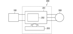
- FIG. 3 is a block diagram showing the configuration of a power conversion system to which a power conversion device according to a fourth embodiment is applied.
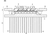
- FIG. 1 is a cross-sectional view of a power module 202 according to the first embodiment.
- FIG. 2 is a top view of the power module 202 according to the first embodiment.
- the power module 202 is a heat sink integrated power module, and includes a power module section 9 and a heat sink 13.
- the power module section 9 includes a plurality of semiconductor chips 1 (semiconductor elements), a lead frame 3 (frame), an insulating sheet 4, a module base 5, a mold section 8, and a plurality of bus bars 10 (external terminals). We are prepared.
- the plurality of semiconductor chips 1 are mounted on the upper surface (one surface) of the lead frame 3.
- the lead frame 3 is arranged via an insulating sheet 4 attached to the upper surface (one side) of the module base 5.
- the mold section 8 is made of mold resin, and is arranged so that the lower surfaces (other surfaces) of the main terminals 7 and the module base 5, which are part of the lead frame 3, are exposed.
- the module base 5 is sealed.
- the heat sink 13 includes a base portion 11 that is integrated with the lower surface (the other surface) of the module base 5, and a plurality of heat radiation fins 12 that protrude below the base portion 11 (on the opposite side from the module base 5). There is.
- a plurality of concave fitting portions 5a are provided on the lower surface (the other surface) of the module base 5. Further, on the upper surface of the portion of the base portion 11 excluding the outer peripheral portion (the surface on the module base 5 side), a plurality of convex fitted portions 11a that can be fitted with the fitting portion 5a are provided.
- the module base 5 and the heat sink 13 are integrated by fitting the fitting part 5a and the fitted part 11a.
- the fitting portion 5a and the fitted portion 11a may be provided continuously in the depth direction of the module base 5 and the base portion 11, respectively, or may be provided intermittently.
- control terminal 6 and main terminal 7, which are part of the lead frame 3 are formed by performing molding for forming terminals.
- molding for forming terminals is not essential and can be omitted.
- the main terminal 7 and the control terminal 6 are part of the lead frame 3 and are connected to the semiconductor chip 1 inside the mold part 8 by a wiring member (not shown) such as an aluminum wire.
- the wiring member does not necessarily have to be an aluminum wire, and may be electrically connected, for example, by a metal wire such as a copper wire, or a metal plate using a bonding member such as solder.
- the main terminal 7 and the control terminal 6 are integrated by molding in a state where they are exposed from the mold part 8.
- a plurality of (four) main terminals 7 extend in the left-right direction (first direction), which is a direction parallel to the base portion 11 of the heat sink 13, and are exposed from the mold portion 8.
- the two main terminals 7 are formed in a straight line so as to extend leftward from the left end of the molded part 8, and the remaining two main terminals 7 are formed in a straight line so as to extend rightward from the right end of the molded part 8. It is formed in a straight line so as to extend.
- the second main surface (lower surface) of the main terminal 7 opposite to the first main surface (upper surface) faces the heat sink 13
- the first main surface (upper surface) of the main terminal 7 faces the opposite side of the heat sink 13 ( facing upward).
- the thickness of the lead frame 3 including the main terminal 7 and the control terminal 6 is often increased from the viewpoint of current density. For this reason, if an attempt is made to bend the thick lead frame 3 by terminal forming processing, the number of prestons will increase, and there is a concern that the equipment will become larger and the productivity will decrease.
- the second main surface (lower surface) opposite to the first main surface (upper surface) of the main terminal 7 faces the heat sink 13, and the second main surface (lower surface) of the main terminal 7 is opposite to the first main surface (upper surface).
- the upper surface faces the opposite side (upward) from the heat sink 13.
- the bus bar 10 to the main terminal 7
- the length of the main terminal 7 can be shortened. Since the length of the main terminal 7 is shortened, the area of the lead frame 3 including the main terminal 7 can be reduced. Thereby, it becomes possible to take out a large number of shapes from one lead frame (multi-piece cutting), and it is possible to improve productivity.
- the area of the lead frame 3 inside the power module 202 can be increased while the area of the lead frame 3 including the main terminal 7 remains the same. This improves the degree of freedom in the arrangement of the semiconductor chip 1 and the design of electrical wiring, making it possible to improve heat dissipation.
- FIGS. 3A and 3B are top views of a power module 202 according to a modification of the first embodiment.
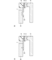
- the main terminal 7 may have an L-shape when viewed from above, and as shown in FIG. 3(b), the main terminal 7 may have a U-shape when viewed from above. It may be.
- the shape of the main terminal 7 is not limited to this and can be freely designed. By adopting such a shape, it is possible to reduce the stress applied to the interface between the main terminal 7 and the molded part 8 when the main terminal 7 and the bus bar 10 are connected. Furthermore, it is also possible to reduce the stress applied to the interface between the main terminal 7 and the molded part 8 when vibration occurs during use of the product, thereby improving the vibration resistance of the product.
- FIG. 4 is a cross-sectional view showing the connection between the main terminal 7 and the bus bar 10 included in the power module 202 according to a modification of the first embodiment.
- the main terminal 7 may have a crank shape when viewed in cross section.
- the main terminal 7 has a first parallel portion 7a exposed from the mold portion 8 in a first direction parallel to the base portion 11 of the heat sink 13, and a first parallel portion 7a exposed from the first parallel portion 7a in a vertical direction. It has a first vertical part 7b extending in the second direction and a second parallel part 7c extending in the first direction from the first vertical part 7b.
- the bus bar 10 is connected to the first main surface of the second parallel portion 7c of the main terminal 7.
- the bent part has an elastic function, so that when the main terminal 7 and the bus bar 10 are connected, the main terminal 7 and the mold It is possible to reduce the stress applied to the interface of the portion 8. Similarly, it is also possible to reduce the stress applied to the interface between the main terminal 7 and the molded part 8 when vibration occurs during use of the product, thereby improving the vibration resistance of the product.
- the shape of the main terminal 7 shown in FIG. 4 requires bending, since the second parallel portion 7c extends in the horizontal direction, for example, one area is It becomes possible to connect a large bus bar 10 in a stable state.
- the power module 202 according to the first embodiment has a structure in which the main terminals 7 are arranged on two sides of the mold part 8 and the control terminals 6 are arranged on the other two sides when viewed from above. be.
- the arrangement of the main terminal 7 and the control terminal 6 is not limited to this.
- 5 and 6 are top views of the power module 202 according to a modification of the first embodiment.
- the main terminal 7 and the control terminals 6 may be arranged on one side and the control terminals 6 on the other two sides, or as shown in FIG. They may be arranged in a mixed manner and can be freely designed.
- FIG. 7 is a cross-sectional view showing a connection between the main terminal 7 and the bus bar 10 provided in the power module 202 according to a modification of the first embodiment by screw fastening.
- FIG. 8 is a top view showing the connection between the main terminal 7 and the bus bar 10 provided in the power module 202 according to the modification of the first embodiment by screw fastening.
- the method of connecting the main terminal 7 and the bus bar 10 by screw fastening using screws 14 and nuts 15 is the simplest and most productive method. Screw fastening will be explained.
- a cut hole 7d is provided in the main terminal 7, and a cut hole 10a is provided in the bus bar 10 at a location corresponding to the cut hole 7d. Screw fastening is performed by fastening the nut 15 to the shaft of the screw 14 with the shaft of the screw 14 inserted through the cut hole 10a and the cut hole 7d.
- the bus bar 10 may be arranged above the main terminal 7, the screw 14 is arranged above the bus bar 10, the nut 15 is arranged below the main terminal 7, and the connection can be made by fastening the screws, or the bus bar 10 may be connected to the main terminal 7.
- the screw 14 may be placed above the main terminal 7, the nut 15 may be placed below the bus bar 10, and the connection may be made by fastening the screws. Note that it is also possible to replace the screws 14 and nuts 15 in each arrangement and perform screw fastening, although productivity decreases.
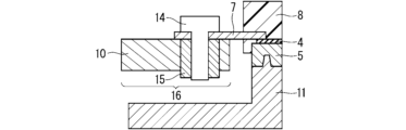
- FIG. 9 is a cross-sectional view showing a connection between the main terminal 7 of the power module 202 according to the modification of the first embodiment and the nut-equipped bus bar 16 by screw fastening. Furthermore, in order to connect the bus bars 10 with high productivity, as shown in FIG. 9, a bus bar 16 with a nut in which a nut 15 is inserted into the bus bar 10 is used, and the main terminal 7 and the bus bar 16 with a nut are connected by screw fastening. It is also possible to do so.
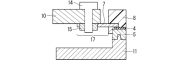
- FIG. 10 is a sectional view showing a connection between the main terminal 17 with a nut and the bus bar 10 provided in the power module 202 according to a modification of the first embodiment by screw fastening.
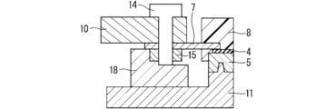
- FIG. 11 is a cross-sectional view showing a connection by screw fastening between the main terminal 7, on which the screw fastening auxiliary member 18 provided in the power module 202 according to the modification of the first embodiment, and the bus bar 10 are arranged.
- a main terminal 17 with a nut in which a nut 15 is inserted into the main terminal 7, and to connect it to the bus bar 10 by screw fastening.
- a lead frame 3 in which a nut 15 is inserted into the main terminal 7 is used and molded.
- the nut 15 is inserted into the main terminal 7 after molding and terminal forming processing. In either method, the main terminal 17 with a nut and the bus bar 10 can be connected by screw fastening.
- main terminal 7 when the main terminal 7 is formed to extend in the horizontal direction, when screwing the main terminal 7 and the bus bar 10, productivity can be improved by inserting an auxiliary screw fastening member 18 as shown in FIG. It is possible to easily connect the main terminal 7 and the bus bar 10 by fastening screws.
- FIG. 12 is a cross-sectional view showing the positional relationship between the main terminal 7 and the screw fastening auxiliary member 18 included in the power module 202 according to a modification of the first embodiment.
- FIG. 13 is a cross-sectional view showing the positional relationship between the main terminal 7 and the screw fastening auxiliary member 20 with elastic function included in the power module 202 according to the modification of the first embodiment.
- FIG. 14 is a cross-sectional view showing the connection between the main terminal 7 and the bus bar 10 of the power module 202 according to the modification of the first embodiment using the solder 2.
- FIG. 15 is a cross-sectional view showing a welded connection between the main terminal 7 and the bus bar 10 included in the power module 202 according to the modification of the first embodiment.
- FIG. 16 is a cross-sectional view showing the connection between the main terminal 7 and the bus bar 10 provided in the power module 202 according to the modification of the first embodiment by crimping.
- the main terminal 7 and the bus bar 10 can be connected not only by screw fastening, but also by a bonding material such as solder 2 as shown in FIG. 14, by welding as shown in FIG. 15, and by welding as shown in FIG. Connection can be made using any connection method, such as crimping. With either connection method, sufficient connection strength can be obtained, contact electrical resistance and contact thermal resistance can be stably reduced, and the contact area between bus bar 10 and main terminal 7 can be increased. A rise in temperature of the main terminal 7 can be suppressed.
- the reference numeral 22a in FIG. 15 indicates a welded portion.
- connection method that combines several connection methods, such as screw fastening and crimping, is also possible.
- connection strength is further improved than when only one type is used, the contact electrical resistance and the contact thermal resistance can be more stably reduced, and the contact between the bus bar 10 and the main terminal 7 is improved. Since the area can be further increased, the temperature rise of the main terminal 7 during use of the product can be further suppressed.
- FIG. 1 shows an example in which a caulking heat sink is used as the heat sink 13, in which the base portion 11 and the plurality of radiation fins 12 are integrated by caulking.
- the base portion 11 is processed by machining, die-casting, forging, extrusion, or the like, and is made of aluminum or an aluminum alloy.
- a plate material such as aluminum or aluminum alloy for the heat dissipation fin 12, it was possible to achieve both workability and heat dissipation.
- both the base part 11 and the heat dissipation fins 12 are not limited to aluminum materials, and each may be made of a combination of different materials.
- the heat dissipation ability is further improved than in the case of an aluminum-based material.
- the heat sink 13 is not limited to a caulked heat sink, and may be an extruded heat sink manufactured by extrusion as shown in FIG. 17, a cut heat sink manufactured by cutting, or a forged heat sink manufactured by forging.
- a die-cast heat sink produced by die-casting as shown in FIG. 18 may also be used.
- the module base 5 and the heat sink 13 may be integrated with a bonding material such as solder 2 and adhesive. Note that it is also possible to integrate the module base 5 and the heat sink 13 by combining a plurality of methods, such as using caulking and a bonding material.
- the module base 5 is processed by machining, die-casting, forging, extrusion, or the like, and is made of aluminum or an aluminum alloy.
- the material of the module base 5 is not limited to aluminum material, but by using a copper-based plate material that has higher thermal conductivity than aluminum-based material, the heat dissipation ability is further improved than in the case of aluminum-based material. .
- the semiconductor chip 1 may be made of silicon, or may be a wide bandgap semiconductor such as silicon carbide or gallium nitride.
- the material of the lead frame 3 and the bus bar 10 is preferably a copper-based material or an aluminum-based material from the viewpoint of electrical resistivity and workability, but it is not limited to this as long as it is a metal material.
- the power module 202 includes the semiconductor chip 1, the lead frame 3 on which the semiconductor chip 1 is mounted on one side, and the module base 5 on which the lead frame 3 is arranged on one side. , a main terminal 7 that is a part of the lead frame 3, a mold part 8 that seals the semiconductor chip 1, the lead frame 3, and the module base 5 so that the main terminal 7 is exposed, and a mold part 8 that is exposed from the mold part 8.
- the main terminal 7 includes a heat sink 13 integrated with the other surface of the module base 5 and a bus bar 10 connected to the first main surface of the main terminal 7 or the second main surface opposite to the first main surface.
- the second main surface faces the heat sink 13, and the first main surface of the main terminal 7 faces the opposite side from the heat sink 13.
- the method for manufacturing the power module 202 also includes a step (a) of connecting the bus bar 10 to the first or second main surface of the main terminal 7 by screw fastening, bonding, or crimping.
- the bus bar 10 can be connected to the main terminal 7, so that it is possible to suppress a rise in temperature of the main terminal 7. As a result, a large current can flow through the power module 202.
- bus bar 10 is connected to the first or second main surface of the main terminal 7 with the screw 14 and nut 15, it is possible to connect the bus bar 10 to the main terminal 7 in a simple manner and with high productivity. Can be done.
- the heat sink 13 has a base portion 11 that is integrated with the other surface of the module base 5, and a plurality of heat dissipation fins 12 that protrude from the base portion 11 on the side opposite to the module base 5. , extends in a first direction parallel to the base portion 11 of the heat sink 13 and is exposed from the mold portion 8 .
- the main terminal 7 also has a first parallel part 7a exposed from the mold part 8 in a first direction parallel to the base part 11 of the heat sink 13, and a second direction perpendicular to the first parallel part 7a.
- the bus bar 10 has a first vertical portion 7b extending in the first direction, and a second parallel portion 7c extending in the first direction from the first vertical portion 7b. 7c.
- a fitting portion 5a is provided on the other surface of the module base 5, and a fitted portion 11a that can be fitted with the fitting portion 5a is provided on the surface of the base portion 11 of the heat sink 13 on the module base 5 side.
- the module base 5 and the heat sink 13 are integrated by fitting the fitting part 5a and the fitted part 11a.
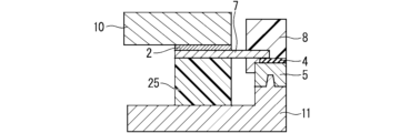
- FIG. 20 is a cross-sectional view of the power module 202 according to the second embodiment.
- FIG. 21 is a top view of the power module 202 according to the second embodiment. Note that, in the second embodiment, the same components as those described in the first embodiment are given the same reference numerals, and a description thereof will be omitted.
- the power module 202 further includes a terminal block 25 (structural member for displacement control), compared to the case of the first embodiment.
- the terminal block 25 is fixed onto the outer circumference of the base portion 11 of the heat sink 13 and is disposed between the main terminal 7 and the base portion 11.
- the bus bar 10 is arranged above the main terminal 7, and the terminal block 25 is arranged below the main terminal 7, but the bus bar 10 is arranged below the main terminal 7. , and further a terminal block 25 may be arranged below the bus bar 10.
- the material of the terminal block 25 is resin from the viewpoint of workability and insulation. However, it does not necessarily need to be made of resin, and may be made of metal material.
- FIG. 22 is a cross-sectional view showing the connection between the terminal block 25 and the heat sink 13 provided in the power module 202 according to the second embodiment by screw fastening.
- FIG. 23 is a cross-sectional view showing the connection between the terminal block 25 and the heat sink 13 of the power module 202 according to the modification of the second embodiment using the solder 2.
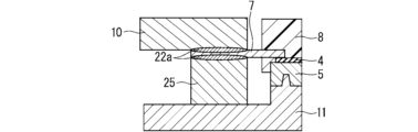
- FIG. 24 is a cross-sectional view showing a welded connection between a terminal block 25 and a heat sink 13 included in a power module 202 according to a modification of the second embodiment.
- FIG. 24 is a cross-sectional view showing a welded connection between a terminal block 25 and a heat sink 13 included in a power module 202 according to a modification of the second embodiment.
- FIG. 25 is a cross-sectional view showing a connection between a terminal block 25 and a heat sink 13 provided in a power module 202 according to a modification of the second embodiment by crimping.
- FIG. 26 is a cross-sectional view showing a connection between the main terminal 7 and the bus bar 10 provided in the power module 202 according to the modification of the second embodiment by screw fastening.
- FIG. 27 is a cross-sectional view showing the connection between the main terminal 7 and the bus bar 10 of the power module 202 according to the modified example of the second embodiment using the solder 2.
- FIG. 28 is a cross-sectional view showing a welded connection between the main terminal 7 and the bus bar 10 provided in the power module 202 according to the modification of the second embodiment.
- FIG. 29 is a cross-sectional view showing a connection by crimp between the main terminal 7 and the bus bar 10 provided in the power module 202 according to the modification of the second embodiment.
- the terminal block 25 and the base portion 11 of the heat sink 13 can be fixed by screw fastening as shown in FIG. 22, by a bonding material such as solder 2 as shown in FIG. 23, by welding as shown in FIG. 24, or by welding as shown in FIG. Alternatively, any connection method such as connection by crimp as shown in FIG. 25 may be used.
- the main terminal 7 and the bus bar 10 can be connected by screw fastening as shown in FIG. 26, by using a bonding material such as solder 2 as shown in FIG. 27, by welding as shown in FIG. 28, or by welding as shown in FIG. Any connection method may be used, such as connection by crimp as shown in FIG. 29.
- the reference numeral 22a in FIGS. 24 and 28 indicates a welded portion
- the reference numeral 22b in FIG. 25 indicates a crimped portion.
- the displacement applied to the main terminal 7 can be controlled, and the stress applied to the interface between the mold part 8 and the main terminal 7 can be reduced.
- the incidence of defects in the process of connecting the bus bar 10 to the main terminal 7 can be reduced.
- the clearance between the main terminal 7 or bus bar 10 and the terminal block 25 can be controlled when the product is used. As a result, the displacement during vibration can be reduced, so that the stress applied to the interface between the mold part 8 and the main terminal 7 can be reduced, and the vibration resistance of the product can be improved.
- the nut 15 is placed on the terminal block 25 fixed to the base part 11 of the heat sink 13 and the main terminal 7 and the bus bar 10 are connected, or the nut 15 is placed on the terminal block 25 fixed to the base part 11 of the heat sink 13.
- the terminal block 25 By fixing the terminal block 25 to the base portion 11 and connecting the main terminals 7 and the bus bar 10, this can be realized in a simple manner and with good productivity.
- FIGS. 30(a) and 30(b) show a connection between the main terminal 7 and the bus bar 10 by screw fastening using the main terminal 17 with a nut or the bus bar 16 with a nut included in the power module 202 according to a modification of the second embodiment.
- FIG. 30(a) a space 25a for the nut 15 is provided in the terminal block 25, the main terminal 17 with a nut is used, the bus bar 10 is placed above the main terminal 17 with the nut, and the screw is fastened. Connect by.
- a space 25a for the nut 15 is provided in the terminal block 25, a bus bar 16 with a nut is used, the main terminal 7 is placed above the bus bar 16 with a nut, and the screw Connection may be made by fastening.
- solder joint structure it is possible to realize the structure as shown in FIG. 27 with a simple method and high productivity.
- welded structure it can be realized with high productivity by a simple method of welding or brazing as shown in FIG.
- a space 10b for crimping is provided in the bus bar 10, and a main body formed to correspond to the shape of the space 10b is connected from the bus bar 10.
- the bus bar 10 and the main terminal 7 are connected by applying pressure to the terminal 7.
- This simple method is highly productive and can be realized.
- the space 10b has a triangular shape in cross-sectional view
- the space 10b has a trapezoidal shape in cross-sectional view.
- FIG. 31 is a cross-sectional view showing the arrangement of a terminal block 25 having a positioning structure included in a power module 202 according to a modification of the second embodiment.
- a positioning groove 26a is provided in the base portion 11 of the heat sink 13, and a convex positioning portion 26 that can fit into the groove 11b is provided in the terminal block 25, thereby simplifying the terminal block mounting process. It can be simplified and productivity can be improved.
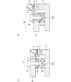
- FIGS. 32(a) and 32(b) are cross-sectional views showing the arrangement of a terminal block 25 having a positioning structure included in a power module 202 according to a modification of the second embodiment
- FIG. 32(c) is a side view. It is.
- FIGS. 32(d) and 32(e) are top views showing the arrangement of the terminal block 25 having the positioning structure included in the power module 202 according to the modification of the second embodiment.
- the positioning part 26 of the terminal block 25 is not limited to the structure shown in FIG. 31, but can have a structure as shown in FIGS. 32(a) to 32(e), for example, to determine the position of the terminal block 25 in at least one direction. Any structure may be used as long as it has a structure.
- a positioning groove 26a may be provided in the terminal block 25, and a T-shaped positioning portion 26 may be provided in the base portion 11 when viewed in cross section.
- the entire lower end portion of the terminal block 25 may be used as the positioning portion 26, and the base portion 11 may be provided with a groove 26a into which the positioning portion 26 can fit.
- FIG. 32(a) a positioning groove 26a may be provided in the terminal block 25
- a T-shaped positioning portion 26 may be provided in the base portion 11 when viewed in cross section.
- the entire lower end portion of the terminal block 25 may be used as the positioning portion 26, and the base portion 11 may be provided with a groove 26a into which the positioning portion 26 can fit.
- FIG. 32(a)
- the base portion 11 may be provided with two convex positioning portions 26, and the terminal block 25 may be provided with two grooves 26a.
- the positioning portion 26 provided on the base portion 11 may have a shape in which two cross shapes are connected when viewed from above.
- both of the two positioning parts 26 provided on the base part 11 may have a cylindrical shape.
- FIG. 33 is a cross-sectional view showing the clearance between the main terminal 7 and the terminal block 25 included in the power module 202 according to the modification of the second embodiment.
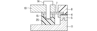
- FIG. 34 is a sectional view showing the connection between the main terminal 7 and the bus bar 10 by screw fastening when there is a clearance between the main terminal 7 and the terminal block 25 provided in the power module 202 according to the modification of the second embodiment.
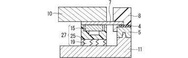
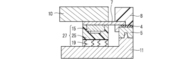
- FIG. 35 is a cross-sectional view showing the clearance between the main terminal 7 and the terminal block 25 when the terminal block 27 with elastic function included in the power module 202 according to the modification of the second embodiment is used.
- the positional relationship in the height direction between the main terminal 7 and the terminal block 25 does not necessarily have zero clearance, as shown in FIG. That is, as shown in FIG. 33, there is either a state in which a clearance (displacement) exists between the main terminal 7 and the terminal block 25, or a state in which the main terminal 7 and the terminal block 25 interfere.
- the displacement applied when connecting the main terminal 7 and the bus bar 10 that is, the clearance between the main terminal 7 and the terminal block 25 is large, there is a large Since there is a concern that stress may be applied to the interface and cause peeling and cracking, it is desirable to reduce the clearance between the main terminal 7 and the terminal block 25.
- the terminal block 25 with the nut 15 is used to connect the main terminal 7 and the bus bar 10 by screw fastening, but the main terminal 7 and the bus bar 10 can be connected by soldering, welding, or Even in the case of connection by crimping, the same effect can be obtained by using the terminal block 27 with elastic function.
- the main terminal 7 may also have a shape as shown in FIG. , or between the bus bar 10 and the base part 11, which are arranged below the second parallel part 7c.
- the power module 202 further includes the terminal block 25 fixed on the base portion 11 of the heat sink 13 and disposed between the main terminal 7 or the bus bar 10 and the base portion 11. ing.
- the method for manufacturing the power module 202 also includes the step (a) of connecting the bus bar 10 to the first or second main surface of the main terminal 7 by screwing, joining, or crimping, and connecting the terminal block 25 to the main terminal. 7 or the bus bar 10, and a step (b) of fixing the heat sink 13 to the base portion 11 of the heat sink 13.
- the displacement applied to the main terminal 7 can be controlled with good productivity, and the stress applied to the interface between the main terminal 7 and the molded part 8 when the main terminal 7 and the bus bar 10 are connected can be reduced.
- the clearance between the main terminal 7 or bus bar 10 and the terminal block 25 can be controlled, and the stress applied to the interface between the main terminal 7 and the molded part 8 during vibration can be reduced. Therefore, the vibration resistance of the product is improved.
- the power module and the terminal block 25 vibrate together when vibrating, thereby further improving the vibration resistance of the product.
- the power module 202 further includes an elastic material 19 disposed between the terminal block 25 and the base part 11, there is no clearance in the height direction between the main terminal 7 or the bus bar 10 and the terminal block 25. Even when the elastic material 19 is present, it is possible to bring the main terminal 7 or the bus bar 10 into contact with the terminal block 25 .
- a terminal block 25 fixed to the heat sink 13 is connected to the main terminal 7.
- the bus bar 10 is placed above the main terminal 7, and the terminal block 25 is connected to the bottom of the main terminal 7.
- the bus bar 10 is placed below the main terminal 7.
- a terminal block 25 may be arranged below the bus bar 10.
- the terminal block 25 and the base portion 11 of the heat sink 13 can be fixed by screw fastening as shown in FIG. 22, by a bonding material such as solder 2 as shown in FIG. 23, by welding as shown in FIG. 24, or by welding as shown in FIG. Alternatively, any connection method such as connection by crimp as shown in FIG. 25 may be used.
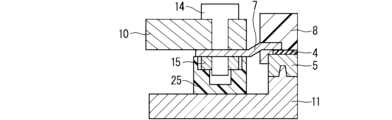
- FIG. 36 is a cross-sectional view showing a connection between the main terminal 7, the bus bar 10, and the terminal block 25 provided in the power module 202 according to the third embodiment by screw fastening.
- FIG. 37 is a cross-sectional view showing the connection of the main terminal 7, bus bar 10, and terminal block 25 of the power module 202 according to the third embodiment with the solder 2.
- FIG. 38 is a cross-sectional view showing a welded connection between the main terminal 7, the bus bar 10, and the terminal block 25 included in the power module 202 according to the third embodiment.
- FIGS. 39(a) and 39(b) are cross-sectional views showing the connection of the main terminal 7, the bus bar 10, and the terminal block 25 provided in the power module 202 according to the third embodiment by crimping.
- the main terminal 7, the bus bar 10, and the terminal block 25 can be connected by screw fastening as shown in FIG. 36, by using a bonding material such as solder 2 as shown in FIG. 37, or by welding as shown in FIG. Any connection method may be used, such as connection, connection by crimping as shown in FIGS. 39(a) and 39(b), etc.
- Any connection method may be used, such as connection, connection by crimping as shown in FIGS. 39(a) and 39(b), etc.
- the nut 15 can be fixed to the terminal block 25 by inserting the nut 15 during molding of the terminal block 25, by press-fitting the nut 15 after molding the terminal block 25, or by using a bonding material to fasten the nut 15. Any method such as bonding may be used.
- FIG. 40 is a cross-sectional view showing a terminal block 25 having a metal member 28 for preventing nut removal, which is included in the power module 202 according to the third embodiment.
- a space 25a for arranging the nut 15 is provided in the terminal block 25, the nut 15 is arranged in the space 25a, and the nut 15 is placed on top of the nut 15.
- a U-shaped metal member 28 may be placed in cross-sectional view to prevent the nut from coming off, and the metal member 28 may be inserted into the terminal block 25 with the metal member 28 restricting upward movement of the nut 15. .
- a space 25b for crimp is provided in the terminal block 25, and pressure is applied from the bus bar 10 to the main terminal 7 and the terminal block 25 to connect the main terminal 7.
- by connecting the main terminal 7 and the bus bar 10 to the terminal block 25 by applying pressure to the main terminal 7 and the terminal block 25, it is possible to achieve this in a simple manner and with good productivity. Since the main terminal 7 and the bus bar 10 are connected to the terminal block 25 fixed to the heat sink 13 that is integrated with the power module section 9, the stress applied to the main terminal 7 due to vibrations generated during product use can be reduced. Therefore, the vibration resistance of the product is improved.
- FIG. 41 is a sectional view showing a state of the power module 202 according to the third embodiment when the product is in use.
- FIG. 42 is a sectional view showing a typical power module 302 when the product is in use.
- the heat sink 13 is fixed to the unit frame 29 of the product by screw fastening or the like.
- a terminal block 30 is arranged inside the power module 302, and a metal member is arranged between the power module part 9 and the heat sink 13, that is, below the insulating member 4.
- the power module part 9 and the heat sink 13 are fixed with screws 14 with a heat dissipating member 34 such as thermal conductive grease interposed between the power module part 32 and the base part 11 . Therefore, when the product vibrates, the unit frame 29 and the heat sink 13 vibrate in a fixed state, but the parts (main terminals 7 and It vibrates separately from the bus bar 10). As a result, excessive stress due to vibration is applied between the main terminal 7 and the bus bar 10, which may cause problems such as terminal breakage.
- the power module 202 according to the third embodiment as shown in FIG. 41 has a configuration of the terminal block 25 fixed to the heat sink 13, the main terminal 7, and the bus bar 10 connected to the main terminal 7.
- the power module 202 fixed to the unit frame 29 and each connection part vibrate together. Therefore, it is possible to reduce the stress applied to the interface between the mold part 8 and the main terminal 7 when the product vibrates, and the vibration resistance of the product is improved.
- FIG. 43 is a cross-sectional view showing the clearance between the main terminal 7 and the terminal block 25 included in the power module 202 according to the third embodiment.
- FIG. 44 is a cross-sectional view showing the connection of the main terminal 7, bus bar 10, and terminal block 25 by screw fastening when a clearance exists between the main terminal 7 and the terminal block 25 included in the power module 202 according to the third embodiment.
- FIG. 45 is a cross-sectional view showing the clearance between the main terminal 7 and the terminal block 25 when the terminal block 27 with elastic function included in the power module 202 according to the third embodiment is used.
- the mold part 8 and the main Since there is a concern that a large stress may be applied to the interface between the terminals 7 and peeling or cracking may occur at the interface, it is desirable to reduce the clearance between the main terminal 7 and the terminal block 25 on which the nut 15 is arranged.
- the terminal block 25 with the nut 15 is used to connect the main terminal 7 and the bus bar 10 by screw fastening, but the main terminal 7 and the bus bar 10 can be connected by soldering, welding, or Even in the case of connection by pressure welding, the same effect can be obtained by using the terminal block 27 with elastic function.
- the main terminal 7 may also have a shape as shown in FIG. , or between the bus bar 10 and the base part 11, which are arranged below the second parallel part 7c.
- the terminal block 25 fixed to the heat sink 13 is connected to the main terminal 7, so stress applied to the main terminal 7 due to vibrations generated when the product is used. can be reduced, improving the vibration resistance of the product.
- the power module 202 according to the first to third embodiments described above is applied to a power conversion device.
- Application of the power module 202 according to Embodiments 1 to 3 is not limited to a specific power conversion device, but hereinafter, as Embodiment 4, the power module 202 according to Embodiments 1 to 3 is applied to a three-phase inverter. A case where module 202 is applied will be explained.
- FIG. 46 is a block diagram showing the configuration of a power conversion system to which the power conversion device according to this embodiment is applied.
- the power conversion system shown in FIG. 46 is composed of a power source 100, a power conversion device 200, and a load 300.
- Power supply 100 is a DC power supply and supplies DC power to power conversion device 200.
- the power source 100 can be composed of various things, for example, it can be composed of a DC system, a solar battery, a storage battery, or it can be composed of a rectifier circuit or an AC/DC converter connected to an AC system. Good too.
- the power supply 100 may be configured with a DC/DC converter that converts DC power output from a DC system into predetermined power.
- the power conversion device 200 is a three-phase inverter connected between the power source 100 and the load 300, converts the DC power supplied from the power source 100 into AC power, and supplies the AC power to the load 300.
- the power conversion device 200 includes a main conversion circuit 201 that converts DC power into AC power and outputs it, and a control circuit 203 that outputs a control signal for controlling the main conversion circuit 201 to the main conversion circuit 201. It is equipped with
- the load 300 is a three-phase electric motor driven by AC power supplied from the power conversion device 200.
- the load 300 is not limited to a specific application, but is a motor installed in various electrical devices, and is used, for example, as a motor for a hybrid vehicle, an electric vehicle, a railway vehicle, an elevator, or an air conditioner.
- the main conversion circuit 201 includes a switching element (not shown) and a freewheeling diode (not shown), and when the switching element switches, it converts DC power supplied from the power supply 100 into AC power, and converts the DC power supplied from the power supply 100 into AC power. Supply to 300.
- the main conversion circuit 201 is a two-level three-phase full bridge circuit, and has six switching elements and each switching element. It can be constructed from six freewheeling diodes arranged in antiparallel.
- the power module 202 according to any one of the first to third embodiments described above is applied to at least one of each switching element and each freewheeling diode of the main conversion circuit 201.
- the six switching elements are connected in series every two switching elements to constitute upper and lower arms, and each upper and lower arm constitutes each phase (U phase, V phase, W phase) of the full bridge circuit.
- the output terminals of the upper and lower arms, that is, the three output terminals of the main conversion circuit 201, are connected to the load 300.
- the main conversion circuit 201 includes a drive circuit (not shown) that drives each switching element, but the drive circuit may be built in the power module 202 or a drive circuit may be provided separately from the power module 202.
- the configuration may include the following.
- the drive circuit generates a drive signal for driving the switching element of the main conversion circuit 201 and supplies it to the control electrode of the switching element of the main conversion circuit 201.
- a drive signal that turns the switching element on and a drive signal that turns the switching element off are output to the control electrode of each switching element.
- the drive signal When keeping the switching element in the on state, the drive signal is a voltage signal (on signal) that is greater than or equal to the threshold voltage of the switching element, and when the switching element is kept in the off state, the drive signal is a voltage signal that is less than or equal to the threshold voltage of the switching element. signal (off signal).
- the control circuit 203 controls the switching elements of the main conversion circuit 201 so that the desired power is supplied to the load 300. Specifically, based on the power to be supplied to the load 300, the time (on time) during which each switching element of the main conversion circuit 201 should be in the on state is calculated. For example, the main conversion circuit 201 can be controlled by PWM control that modulates the on-time of the switching element according to the voltage to be output. Then, a control command (control signal) is given to the drive circuit included in the main conversion circuit 201 so that an on signal is output to the switching element that should be in the on state at each time, and an off signal is output to the switching element that should be in the off state. Output.
- the drive circuit outputs an on signal or an off signal as a drive signal to the control electrode of each switching element according to this control signal.
- the power module 202 according to Embodiments 1 to 3 is applied as the switching element and the free wheel diode of the main conversion circuit 201, so it is possible to improve productivity.
- the power module 202 according to Embodiments 1 to 3 is applied to a two-level three-phase inverter.
- the present invention is not limited to this and can be applied to various power conversion devices.
- a two-level power converter is used, but a three-level or multi-level power converter may also be used, and in the case of supplying power to a single-phase load, a single-phase inverter is used.
- the power modules 202 according to Nos. 1 to 3 may be applied.
- the power module 202 according to Embodiments 1 to 3 can be applied to a DC/DC converter or an AC/DC converter.
- the power conversion device to which the power module 202 according to Embodiments 1 to 3 is applied is not limited to the case where the above-mentioned load is an electric motor, but is, for example, an electrical discharge machine, a laser processing machine, or an induction heating cooking It can also be used as a power supply device for a device or a non-contact power supply system, and furthermore, it can be used as a power conditioner for a solar power generation system, a power storage system, etc.
- a semiconductor element a frame with the semiconductor element mounted on one side; a module base with the frame arranged on one side; a main terminal that is part of the frame; a mold part that seals the semiconductor element, the frame, and the module base so that the main terminal is exposed; a heat sink having a base part integrated with the other surface of the module base exposed from the mold part, and a plurality of heat radiation fins protruding from the base part on a side opposite to the module base; an external terminal connected to a first main surface of the main terminal or a second main surface opposite to the first main surface; a displacement control structural member fixed on the base portion of the heat sink and disposed between the main terminal or the external terminal and the base portion; The second main surface of the main terminal faces the heat sink, The first main surface of the main terminal faces a side opposite to the heat sink.
- the main terminal has a first parallel part exposed from the mold part in a first direction parallel to the base part of the heat sink, and extends in a second direction perpendicular to the first parallel part. and a second parallel part extending in the first direction from the first vertical part,
- appendix 6 The power module according to appendix 5, further comprising an elastic material disposed between the displacement control structural member and the base portion.
- a fitting portion is provided on the other surface of the module base, A fitted portion capable of fitting with the fitting portion is provided on the module base side surface of the base portion of the heat sink, The power module according to appendix 3, wherein the module base and the heat sink are integrated by fitting the fitting part and the fitted part.
- a fitting portion is provided on the other surface of the module base, A fitted portion capable of fitting with the fitting portion is provided on the module base side surface of the base portion of the heat sink,
- the power module according to appendix 4 wherein the module base and the heat sink are integrated by fitting the fitting part and the fitted part.
- Appendix 9 A method for manufacturing the power module according to appendix 1, comprising: (a) connecting the external terminal to the first main surface or the second main surface of the main terminal by screw fastening, joining, or crimping; (b) fixing the displacement control structural member to the base portion of the heat sink while in contact with the main terminal or the external terminal; A method for manufacturing a power module.
- Appendix 10 A main conversion circuit that has the power module described in Appendix 1 and converts and outputs input power; a control circuit that outputs a control signal for controlling the main conversion circuit to the main conversion circuit; A power converter equipped with
Landscapes
- Inverter Devices (AREA)
Priority Applications (3)
| Application Number | Priority Date | Filing Date | Title |
|---|---|---|---|
| JP2024521649A JP7678937B2 (ja) | 2022-05-16 | 2023-04-27 | パワーモジュール、パワーモジュールの製造方法、および電力変換装置 |
| CN202380039817.7A CN119183607A (zh) | 2022-05-16 | 2023-04-27 | 功率模块、功率模块的制造方法及电力变换装置 |
| US18/856,188 US20250246512A1 (en) | 2022-05-16 | 2023-04-27 | Power module, method of manufacturing power module, and power conversion device |
Applications Claiming Priority (2)
| Application Number | Priority Date | Filing Date | Title |
|---|---|---|---|
| JP2022079918 | 2022-05-16 | ||
| JP2022-079918 | 2022-05-16 |
Publications (1)
| Publication Number | Publication Date |
|---|---|
| WO2023223804A1 true WO2023223804A1 (ja) | 2023-11-23 |
Family
ID=88835017
Family Applications (1)
| Application Number | Title | Priority Date | Filing Date |
|---|---|---|---|
| PCT/JP2023/016649 Ceased WO2023223804A1 (ja) | 2022-05-16 | 2023-04-27 | パワーモジュール、パワーモジュールの製造方法、および電力変換装置 |
Country Status (4)
| Country | Link |
|---|---|
| US (1) | US20250246512A1 (https=) |
| JP (1) | JP7678937B2 (https=) |
| CN (1) | CN119183607A (https=) |
| WO (1) | WO2023223804A1 (https=) |
Cited By (1)
| Publication number | Priority date | Publication date | Assignee | Title |
|---|---|---|---|---|
| WO2025115274A1 (ja) * | 2023-11-29 | 2025-06-05 | Astemo株式会社 | パワー半導体装置 |
Citations (3)
| Publication number | Priority date | Publication date | Assignee | Title |
|---|---|---|---|---|
| JP2011160519A (ja) * | 2010-01-29 | 2011-08-18 | Honda Motor Co Ltd | 電力変換装置 |
| JP2016100940A (ja) * | 2014-11-19 | 2016-05-30 | 株式会社ケーヒン | 電力変換装置 |
| WO2018097027A1 (ja) * | 2016-11-24 | 2018-05-31 | 三菱電機株式会社 | 半導体装置およびその製造方法 |
Family Cites Families (1)
| Publication number | Priority date | Publication date | Assignee | Title |
|---|---|---|---|---|
| CN116762170A (zh) * | 2021-01-22 | 2023-09-15 | 三菱电机株式会社 | 功率半导体装置及其制造方法以及电力转换装置 |
-
2023
- 2023-04-27 CN CN202380039817.7A patent/CN119183607A/zh active Pending
- 2023-04-27 WO PCT/JP2023/016649 patent/WO2023223804A1/ja not_active Ceased
- 2023-04-27 JP JP2024521649A patent/JP7678937B2/ja active Active
- 2023-04-27 US US18/856,188 patent/US20250246512A1/en active Pending
Patent Citations (3)
| Publication number | Priority date | Publication date | Assignee | Title |
|---|---|---|---|---|
| JP2011160519A (ja) * | 2010-01-29 | 2011-08-18 | Honda Motor Co Ltd | 電力変換装置 |
| JP2016100940A (ja) * | 2014-11-19 | 2016-05-30 | 株式会社ケーヒン | 電力変換装置 |
| WO2018097027A1 (ja) * | 2016-11-24 | 2018-05-31 | 三菱電機株式会社 | 半導体装置およびその製造方法 |
Cited By (1)
| Publication number | Priority date | Publication date | Assignee | Title |
|---|---|---|---|---|
| WO2025115274A1 (ja) * | 2023-11-29 | 2025-06-05 | Astemo株式会社 | パワー半導体装置 |
Also Published As
| Publication number | Publication date |
|---|---|
| US20250246512A1 (en) | 2025-07-31 |
| JPWO2023223804A1 (https=) | 2023-11-23 |
| CN119183607A (zh) | 2024-12-24 |
| JP7678937B2 (ja) | 2025-05-16 |
Similar Documents
| Publication | Publication Date | Title |
|---|---|---|
| US11322432B2 (en) | Semiconductor module and power conversion apparatus | |
| JP5206822B2 (ja) | 半導体装置 | |
| JP3793407B2 (ja) | 電力変換装置 | |
| US10515863B2 (en) | Power module and power conversion apparatus including case and elastic member | |
| JP6257478B2 (ja) | 電力用半導体装置 | |
| JP6263311B2 (ja) | 電力変換装置 | |
| US20190131210A1 (en) | Semiconductor module, method for manufacturing the same and electric power conversion device | |
| JP6667737B1 (ja) | 半導体モジュールおよび電力変換装置 | |
| JP6566927B2 (ja) | 半導体装置および電力変換装置 | |
| JP6575739B1 (ja) | 半導体装置、半導体装置の製造方法および電力変換装置 | |
| WO2023223804A1 (ja) | パワーモジュール、パワーモジュールの製造方法、および電力変換装置 | |
| JP5202366B2 (ja) | 半導体装置 | |
| JP5948106B2 (ja) | パワー半導体モジュール及びそれを用いた電力変換装置 | |
| JPWO2018180580A1 (ja) | 半導体装置および電力変換装置 | |
| JP2009094164A (ja) | インバータ装置における電力用半導体素子 | |
| JP7584668B2 (ja) | パワーモジュールおよび電力変換装置 | |
| JP5202365B2 (ja) | 半導体装置 | |
| JP7535909B2 (ja) | 電力用半導体装置およびその製造方法ならびに電力変換装置 | |
| WO2024171848A1 (ja) | パワーモジュール、パワーモジュールの製造方法、および電力変換装置 | |
| CN114567186A (zh) | 功率转换装置及其制造方法 | |
| WO2025094656A1 (ja) | 半導体装置、半導体装置の製造方法、および電力変換装置 | |
| JP2007143218A (ja) | パワーモジュール及び基板 | |
| WO2025253910A1 (ja) | パワーモジュールおよび電力変換装置 | |
| WO2024252463A1 (ja) | 電力変換装置、電動車両駆動装置、及び電力変換装置の製造方法 | |
| WO2026074615A1 (ja) | 半導体装置および電力変換装置 |
Legal Events
| Date | Code | Title | Description |
|---|---|---|---|
| 121 | Ep: the epo has been informed by wipo that ep was designated in this application |
Ref document number: 23807414 Country of ref document: EP Kind code of ref document: A1 |
|
| WWE | Wipo information: entry into national phase |
Ref document number: 2024521649 Country of ref document: JP |
|
| WWE | Wipo information: entry into national phase |
Ref document number: 18856188 Country of ref document: US |
|
| NENP | Non-entry into the national phase |
Ref country code: DE |
|
| 122 | Ep: pct application non-entry in european phase |
Ref document number: 23807414 Country of ref document: EP Kind code of ref document: A1 |
|
| WWP | Wipo information: published in national office |
Ref document number: 18856188 Country of ref document: US |