WO2023210540A1 - 電動車両 - Google Patents
電動車両 Download PDFInfo
- Publication number
- WO2023210540A1 WO2023210540A1 PCT/JP2023/015976 JP2023015976W WO2023210540A1 WO 2023210540 A1 WO2023210540 A1 WO 2023210540A1 JP 2023015976 W JP2023015976 W JP 2023015976W WO 2023210540 A1 WO2023210540 A1 WO 2023210540A1
- Authority
- WO
- WIPO (PCT)
- Prior art keywords
- heat exchanger
- vehicle
- electric vehicle
- air
- center axis
- Prior art date
- Legal status (The legal status is an assumption and is not a legal conclusion. Google has not performed a legal analysis and makes no representation as to the accuracy of the status listed.)
- Ceased
Links
Images




Classifications
-
- B—PERFORMING OPERATIONS; TRANSPORTING
- B60—VEHICLES IN GENERAL
- B60K—ARRANGEMENT OR MOUNTING OF PROPULSION UNITS OR OF TRANSMISSIONS IN VEHICLES; ARRANGEMENT OR MOUNTING OF PLURAL DIVERSE PRIME-MOVERS IN VEHICLES; AUXILIARY DRIVES FOR VEHICLES; INSTRUMENTATION OR DASHBOARDS FOR VEHICLES; ARRANGEMENTS IN CONNECTION WITH COOLING, AIR INTAKE, GAS EXHAUST OR FUEL SUPPLY OF PROPULSION UNITS IN VEHICLES
- B60K1/00—Arrangement or mounting of electrical propulsion units
-
- B—PERFORMING OPERATIONS; TRANSPORTING
- B60—VEHICLES IN GENERAL
- B60K—ARRANGEMENT OR MOUNTING OF PROPULSION UNITS OR OF TRANSMISSIONS IN VEHICLES; ARRANGEMENT OR MOUNTING OF PLURAL DIVERSE PRIME-MOVERS IN VEHICLES; AUXILIARY DRIVES FOR VEHICLES; INSTRUMENTATION OR DASHBOARDS FOR VEHICLES; ARRANGEMENTS IN CONNECTION WITH COOLING, AIR INTAKE, GAS EXHAUST OR FUEL SUPPLY OF PROPULSION UNITS IN VEHICLES
- B60K11/00—Arrangement in connection with cooling of propulsion units
- B60K11/02—Arrangement in connection with cooling of propulsion units with liquid cooling
- B60K11/04—Arrangement or mounting of radiators, radiator shutters, or radiator blinds
-
- B—PERFORMING OPERATIONS; TRANSPORTING
- B60—VEHICLES IN GENERAL
- B60L—PROPULSION OF ELECTRICALLY-PROPELLED VEHICLES; SUPPLYING ELECTRIC POWER FOR AUXILIARY EQUIPMENT OF ELECTRICALLY-PROPELLED VEHICLES; ELECTRODYNAMIC BRAKE SYSTEMS FOR VEHICLES IN GENERAL; MAGNETIC SUSPENSION OR LEVITATION FOR VEHICLES; MONITORING OPERATING VARIABLES OF ELECTRICALLY-PROPELLED VEHICLES; ELECTRIC SAFETY DEVICES FOR ELECTRICALLY-PROPELLED VEHICLES
- B60L58/00—Methods or circuit arrangements for monitoring or controlling batteries or fuel cells, specially adapted for electric vehicles
- B60L58/10—Methods or circuit arrangements for monitoring or controlling batteries or fuel cells, specially adapted for electric vehicles for monitoring or controlling batteries
- B60L58/24—Methods or circuit arrangements for monitoring or controlling batteries or fuel cells, specially adapted for electric vehicles for monitoring or controlling batteries for controlling the temperature of batteries
- B60L58/26—Methods or circuit arrangements for monitoring or controlling batteries or fuel cells, specially adapted for electric vehicles for monitoring or controlling batteries for controlling the temperature of batteries by cooling
-
- B—PERFORMING OPERATIONS; TRANSPORTING
- B60—VEHICLES IN GENERAL
- B60L—PROPULSION OF ELECTRICALLY-PROPELLED VEHICLES; SUPPLYING ELECTRIC POWER FOR AUXILIARY EQUIPMENT OF ELECTRICALLY-PROPELLED VEHICLES; ELECTRODYNAMIC BRAKE SYSTEMS FOR VEHICLES IN GENERAL; MAGNETIC SUSPENSION OR LEVITATION FOR VEHICLES; MONITORING OPERATING VARIABLES OF ELECTRICALLY-PROPELLED VEHICLES; ELECTRIC SAFETY DEVICES FOR ELECTRICALLY-PROPELLED VEHICLES
- B60L9/00—Electric propulsion with power supply external to the vehicle
- B60L9/16—Electric propulsion with power supply external to the vehicle using AC induction motors
- B60L9/18—Electric propulsion with power supply external to the vehicle using AC induction motors fed from DC supply lines
Definitions
- the present disclosure relates to an electric vehicle that runs using the driving force of a rotating electric machine.
- the vehicle is equipped with a heat exchanger that exchanges heat with the air.
- a heat exchanger includes, for example, a radiator that cools cooling water that has reached a high temperature after passing through an internal combustion engine or the like by exchanging heat with air.
- a heat exchanger is arranged at a position near the front end of the vehicle. This allows a large amount of air to be introduced inside the vehicle and efficiently used for heat exchange.
- the weight of the heat exchanger is relatively large.
- the weight of the heat exchanger to be mounted becomes large. If such a heavy object is placed on the front side of the vehicle, the center of gravity of the entire vehicle will be located closer to the front side, which may reduce the drivability of the vehicle.
- the present disclosure aims to provide an electric vehicle with improved drivability.
- the electric vehicle according to the present disclosure is an electric vehicle that runs using the driving force of a rotating electric machine, and includes front wheels, rear wheels, and a heat exchanger that exchanges heat between the air.
- the center of gravity of the heat exchanger is arranged at a position that is rearward of the rotation center axis of the front wheels and forward of the rotation center axis of the rear wheels.
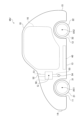
- FIG. 1 is a diagram schematically showing the configuration of a vehicle according to a first embodiment.
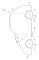
- FIG. 2 is a diagram schematically showing the configuration of a vehicle according to a second embodiment.
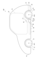
- FIG. 3 is a diagram schematically showing the configuration of a vehicle according to a third embodiment.
- FIG. 4 is a diagram schematically showing the configuration of a vehicle according to a fourth embodiment.
- FIG. 5 is a diagram schematically showing the configuration of a vehicle according to the fifth embodiment.
- FIG. 6 is a diagram schematically showing the configuration of a vehicle according to the sixth embodiment.
- FIG. 7 is a diagram schematically showing the configuration of a vehicle according to a seventh embodiment.
- the vehicle MV does not include an internal combustion engine and is configured as an electric vehicle that runs using the driving force of rotating electric machines 31 and 32.
- the vehicle MV includes a body 10, front wheels 21, rear wheels 22, rotating electric machines 31 and 32, a storage battery 40, and a heat exchanger 50.
- the left side is the front side of the vehicle MV
- the right side is the rear side of the vehicle MV.
- the body 10 forms approximately the entire outer shape of the vehicle MV.
- a cabin 16 is provided inside the body 10, which is a space where the occupant appears.
- the part designated by the reference numeral "11” is a tire house that accommodates a front wheel 21, which will be described later, inside.
- this tire house will also be referred to as "tire house 11.”
- a portion designated by the reference numeral “12” is a tire house that accommodates a rear wheel 22, which will be described later.
- this tire house will also be referred to as "tire house 12.”
- the front wheels 21 are two wheels arranged on the front side out of a total of four wheels provided on the vehicle MV. As described above, each front wheel 21 is housed inside the tire house 11.
- the front wheel 21 is configured integrally with a rotating electric machine 31 that is an in-wheel motor. The driving force of the rotating electric machine 31 causes each front wheel 21 to rotate around the rotation center axis AX1.
- the rear wheels 22 are two wheels arranged on the rear side out of a total of four wheels included in the vehicle MV. As mentioned above, each rear wheel 22 is housed inside the tire house 12.
- the rear wheel 22 is configured integrally with a rotating electric machine 32 that is an in-wheel motor. The driving force of the rotating electric machine 32 causes each rear wheel 22 to rotate around the rotation center axis AX2.
- the rotating electrical machines 31 and 32 are rotating electrical machines for generating driving force for the vehicle MV. As described above, both the rotating electric machines 31 and 32 are configured as in-wheel motors. In this embodiment, one of the rotating electric machines 31 and 32 is provided on each wheel. That is, in the vehicle MV, all four wheels are drive wheels. Instead of such a configuration, a configuration may be adopted in which only one of the front wheels 21 and the rear wheels 22 is the driving wheel. Further, the number of rotating electric machines provided in the vehicle MV may be four as in this embodiment, but may be less than four.
- the storage battery 40 stores electric power necessary for driving the rotating electric machines 31 and 32, and is, for example, a lithium ion battery.
- the power output from the storage battery 40 is converted into AC power by an inverter (not shown), and is supplied to each of the rotating electric machines 31 and 32.
- the storage battery 40 is disposed in the body 10 at a position near the bottom 13.
- the heat exchanger 50 is a heat exchanger for exchanging heat with air. Inside the vehicle MV, water for cooling the storage battery 40, the inverter, etc., that is, cooling water, circulates. The heat exchanger 50 lowers the temperature of the cooling water by exchanging heat between the cooling water and air.
- the vehicle MV is provided with an inlet pipe 51 and an exhaust pipe 53.
- the introduction pipe 51 is a pipe for taking in air for heat exchange from outside the vehicle MV and introducing the air into the heat exchanger 50.
- the upstream end of the introduction pipe 51 is connected to a position near the windshield in the hood of the vehicle MV.
- the opening formed at this connection position that is, the opening formed as an inlet for the air introduced into the heat exchanger 50, will also be referred to as the "inlet 52" hereinafter.
- the introduction port 52 opens upward at a position forward of the vehicle compartment 16 of the vehicle MV.
- the exhaust pipe 53 is a pipe for exhausting the air that has been subjected to heat exchange in the heat exchanger 50 to the outside of the vehicle MV.
- a downstream end of the exhaust pipe 53 is connected to the bottom 13 of the vehicle MV.
- the opening formed at this connection position that is, the opening formed as an outlet for the air that has passed through the heat exchanger 50, will also be referred to as the "exhaust port 54" below.
- the discharge port 54 opens downward at the bottom 13 of the vehicle MV.
- the center of gravity G of the heat exchanger 50 is located on the rear side of the rotation center axis AX1 of the front wheel 21 and on the front side of the rotation center axis AX2 of the rear wheel 22.
- the “rotation center axis AX1 of the front wheels 21” mentioned above refers to the rotation center axis AX1 when the steering angle of the front wheels 21 is zero.
- the “rotation center axis AX2 of the rear wheel 22” in the above refers to the rotation center axis AX2 when the steering angle of the rear wheel 22 is 0.
- the heat exchanger was placed at a position near the front end of the vehicle. This is to introduce a large amount of air into the inside of the vehicle when the vehicle is running, and to make it easier to supply the air to the heat exchanger.
- a heavy object such as a heat exchanger is placed on the front side of the vehicle, the center of gravity of the entire vehicle will be located closer to the front side, which may cause a problem that the drivability of the vehicle will be reduced.
- the above problem is solved by arranging the center of gravity G of the heat exchanger 50 at the position as described above, that is, at a position on the rear side of the rotation center axis AX1 of the front wheel 21.
- the center of gravity G of the heat exchanger 50 is at least on the rear side of the rotation center axis AX1, and that the other part of the heat exchanger 50 should not extend to the front side of the rotation center axis AX1. You can stay there. Similarly, the heat exchanger 50 only needs to have at least its center of gravity G on the front side of the rotation center axis AX2, and the other part of the heat exchanger 50 has to penetrate to the rear side of the rotation center axis AX2. It's okay to stay.
- the heat exchanger 50 can be placed at the above position because the vehicle MV is an electric vehicle and is not equipped with an internal combustion engine that discharges a large amount of heat.
- the heat exchange performance required of the heat exchanger 50 is relatively small, and there is no need to introduce a large amount of air into the heat exchanger 50, so the degree of freedom in the position of the heat exchanger 50 is relatively high. Therefore, in this embodiment, emphasis is placed on the drivability of the vehicle MV, and the heat exchanger 50 is disposed on the rear side of the rotation center axis AX1.
- the position of the inlet port 52 which is an air inlet, is also changed from the conventional one.
- conventional vehicles it has been common to form an air inlet at the front end 14 (front grille) of the vehicle.
- the shape of the end portion 14 needs to have a surface that is generally perpendicular to the front-rear direction.
- the heat exchange performance required of the heat exchanger 50 is relatively small, so there is no restriction on the position of the inlet. Therefore, in this embodiment, as described above, the introduction port 52 is formed at a position other than the end portion 14. Since there are no conventional restrictions on the shape of the end portion 14, the shape of the end portion 14 can be freely set. This makes it possible to improve the Cd value of the vehicle MV to improve fuel efficiency and the design of the vehicle MV.
- the introduction port 52 opens upward at a position that is forward of the cabin 16 of the vehicle MV and near the windshield. At such a position, air pressure is relatively high due to the wind hitting the windshield. Therefore, it is possible to introduce a relatively large amount of air from the introduction port 52 formed at this position.
- the discharge port 54 is formed in the bottom portion 13 of the vehicle MV. Between the bottom part 13 of the vehicle MV and the road surface, wind tends to flow from the front side toward the rear side. Due to the influence of the traveling wind, a negative pressure is generated directly below the exhaust port 54, so that the flow of air from the heat exchanger 50 toward the exhaust port 54 is promoted. That is, in this embodiment, by forming the exhaust port 54 at the above position, it is possible to further increase the flow rate of air passing through the heat exchanger 50.
- a second embodiment will be described with reference to FIG. 2.
- points different from the first embodiment will be mainly explained, and explanations of points common to the first embodiment will be omitted as appropriate.
- This embodiment differs from the first embodiment in the position where the discharge port 54 is formed. As shown in FIG. 2, the discharge port 54 of this embodiment is formed on the outer surface of the vehicle MV. The air that has passed through the heat exchanger 50 is discharged from the exhaust port 54 toward either the right and left sides of the vehicle MV or only one side.
- a third embodiment will be described with reference to FIG. 3.
- points different from the first embodiment will be mainly explained, and explanations of points common to the first embodiment will be omitted as appropriate.
- This embodiment also differs from the first embodiment in the position where the discharge port 54 is formed. As shown in FIG. 3, the discharge port 54 of this embodiment is formed on the inner surface of the tire house 11 of the vehicle MV. The air that has passed through the heat exchanger 50 is discharged toward the front wheels 21 from the discharge port 54.
- a fourth embodiment will be described with reference to FIG. 4.
- points different from the first embodiment will be mainly explained, and explanations of points common to the first embodiment will be omitted as appropriate.
- This embodiment also differs from the first embodiment in the position where the discharge port 54 is formed. As shown in FIG. 4, the discharge port 54 of this embodiment is formed on the inner surface of the compartment 16 of the vehicle MV. The air that has passed through the heat exchanger 50 is discharged toward the inside of the vehicle compartment 16 from the discharge port 54 .
- the vehicle interior 16 can be heated using the air that has passed through the heat exchanger 50 and has been raised in temperature. This makes it possible to reduce the power consumed for heating.
- a fifth embodiment will be described with reference to FIG. 5.
- points different from the first embodiment will be mainly explained, and explanations of points common to the first embodiment will be omitted as appropriate.
- This embodiment differs from the first embodiment in the arrangement of the heat exchanger 50 and the introduction pipe 51 and discharge pipe 53 connected thereto.
- the heat exchanger 50 of this embodiment is placed near the rear wheel 22.
- the position of the center of gravity G of the heat exchanger 50 is on the rear side of the rotation center axis AX1 of the front wheel 21 and further than the rotation center axis AX2 of the rear wheel 22. This position is also on the front side.
- the heat exchanger 50 may be disposed at a position where a portion thereof overlaps with the rear wheel 22.
- the introduction port 52 of this embodiment opens toward the inside of the vehicle compartment 16. Further, the discharge port 54 of this embodiment opens downward in the bottom portion 13 of the vehicle MV, similarly to the first embodiment.
- the entire center of gravity of the vehicle MV can be set at a position on the rear side of the center of the vehicle MV in the longitudinal direction.
- the center of gravity is located close to the drive wheels, so that the drivability of the vehicle MV can be improved.
- a sixth embodiment will be described with reference to FIG. 6. Below, points different from the fifth embodiment described above will be mainly explained, and explanations of points common to the fifth embodiment will be omitted as appropriate.
- This embodiment differs from the fifth embodiment (FIG. 5) in the position where the discharge port 54 is formed. As shown in FIG. 6, the discharge port 54 of this embodiment is formed on the inner surface of the tire house 12 of the vehicle MV. The air that has passed through the heat exchanger 50 is discharged toward the rear wheel 22 from the discharge port 54. Even with such a configuration, the same effects as those described in the fifth embodiment can be achieved.
- a seventh embodiment will be described with reference to FIG. 7.
- points different from the fifth embodiment described above will be mainly explained, and explanations of points common to the fifth embodiment will be omitted as appropriate.
- This embodiment also differs from the fifth embodiment (FIG. 5) in the position where the discharge port 54 is formed.
- the discharge port 54 of this embodiment is formed at the rear end portion 15 of the vehicle MV, and opens toward the rear side. Even with such a configuration, the same effects as those described in the fifth embodiment can be achieved.
- the second embodiment FIG. 2
- Another advantage is that it can be made larger without any problems.
- the discharge port 54 may be formed at a position different from the end portion 15 as long as it is formed toward the rear side of the vehicle MV.
Landscapes
- Engineering & Computer Science (AREA)
- Transportation (AREA)
- Mechanical Engineering (AREA)
- Chemical & Material Sciences (AREA)
- Combustion & Propulsion (AREA)
- Life Sciences & Earth Sciences (AREA)
- Sustainable Development (AREA)
- Sustainable Energy (AREA)
- Power Engineering (AREA)
- Cooling, Air Intake And Gas Exhaust, And Fuel Tank Arrangements In Propulsion Units (AREA)
Abstract
Description
Claims (10)
- 回転電機(31,32)の駆動力によって走行する電動車両(MV)であって、
前輪(21)と、
後輪(22)と、
空気との間で熱交換を行う熱交換器(50)と、を備え、
前記熱交換器の重心(G)が、前記前輪の回転中心軸(AX1)よりも後方側であり、且つ、前記後輪の回転中心軸(AX2)よりも前方側となる位置に配置されている、電動車両。 - 前記熱交換器は、空気と水との間で熱交換を行うものである、請求項1に記載の電動車両。
- 前記熱交換器に導入される空気の入口、である導入口(52)が、前記電動車両のうち前方側の端部(14)以外の位置に形成されている、請求項2に記載の電動車両。
- 前記導入口が、前記電動車両の車室(16)よりも前方側となる位置において、上方側に向けて開口している、請求項3に記載の電動車両。
- 前記導入口が、前記電動車両の車室内に向けて開口している、請求項3に記載の電動車両。
- 前記熱交換器を通過した空気の出口、である排出口(54)が、前記電動車両の底部(13)において、下方側に向けて開口している、請求項2に記載の電動車両。
- 前記熱交換器を通過した空気の出口、である排出口が、車室内に向けて開口している、請求項2に記載の電動車両。
- 前記熱交換器を通過した空気の出口、である排出口が、前記電動車両の外側面に形成されている、請求項2に記載の電動車両。
- 前記熱交換器を通過した空気の出口、である排出口が、前記電動車両のタイヤハウス(11,12)の内面に形成されている、請求項2に記載の電動車両。
- 前記熱交換器を通過した空気の出口、である排出口が、前記電動車両の後方側に向けて開口している、請求項2に記載の電動車両。
Priority Applications (2)
| Application Number | Priority Date | Filing Date | Title |
|---|---|---|---|
| JP2024517290A JP7708311B2 (ja) | 2022-04-25 | 2023-04-21 | 電動車両 |
| CN202380035898.3A CN119072412A (zh) | 2022-04-25 | 2023-04-21 | 电动车辆 |
Applications Claiming Priority (2)
| Application Number | Priority Date | Filing Date | Title |
|---|---|---|---|
| JP2022071269 | 2022-04-25 | ||
| JP2022-071269 | 2022-04-25 |
Publications (1)
| Publication Number | Publication Date |
|---|---|
| WO2023210540A1 true WO2023210540A1 (ja) | 2023-11-02 |
Family
ID=88518900
Family Applications (1)
| Application Number | Title | Priority Date | Filing Date |
|---|---|---|---|
| PCT/JP2023/015976 Ceased WO2023210540A1 (ja) | 2022-04-25 | 2023-04-21 | 電動車両 |
Country Status (3)
| Country | Link |
|---|---|
| JP (1) | JP7708311B2 (ja) |
| CN (1) | CN119072412A (ja) |
| WO (1) | WO2023210540A1 (ja) |
Citations (6)
| Publication number | Priority date | Publication date | Assignee | Title |
|---|---|---|---|---|
| JP2013180614A (ja) * | 2012-02-29 | 2013-09-12 | Toyota Motor Corp | 車両用電池温度制御構造 |
| WO2014049640A1 (ja) * | 2012-09-26 | 2014-04-03 | 川崎重工業株式会社 | 電動車両 |
| JP2018016282A (ja) * | 2016-07-29 | 2018-02-01 | トヨタ自動車株式会社 | 車両構造 |
| JP2020121603A (ja) * | 2019-01-29 | 2020-08-13 | 株式会社デンソー | 機器温調装置 |
| JP2021115899A (ja) * | 2020-01-22 | 2021-08-10 | トヨタ自動車株式会社 | 車両用冷却構造 |
| JP2021115901A (ja) * | 2020-01-22 | 2021-08-10 | トヨタ自動車株式会社 | 車両 |
Family Cites Families (9)
| Publication number | Priority date | Publication date | Assignee | Title |
|---|---|---|---|---|
| JPH04243629A (ja) * | 1991-01-24 | 1992-08-31 | Mazda Motor Corp | 車両用エンジンの冷却構造 |
| JPH1053030A (ja) * | 1996-08-07 | 1998-02-24 | Yoshitake Yamamoto | 車のフロントのデザイン改良のための上部ラジエター |
| JP2005075216A (ja) * | 2003-09-02 | 2005-03-24 | Nissan Motor Co Ltd | 自動車の冷却構造 |
| JP2005096706A (ja) * | 2003-09-26 | 2005-04-14 | Denso Corp | 車両の冷却システム |
| JP2007153260A (ja) * | 2005-12-08 | 2007-06-21 | Denso Corp | 車両用熱交換器の冷却構造 |
| JP5070825B2 (ja) * | 2006-12-05 | 2012-11-14 | トヨタ自動車株式会社 | 燃料電池を搭載した移動体 |
| JP2019196839A (ja) * | 2016-09-09 | 2019-11-14 | 株式会社デンソー | 機器温調装置 |
| JP6672388B2 (ja) * | 2018-06-29 | 2020-03-25 | 本田技研工業株式会社 | 車両の前部構造 |
| JP7279652B2 (ja) * | 2020-01-22 | 2023-05-23 | トヨタ自動車株式会社 | 車両 |
-
2023
- 2023-04-21 WO PCT/JP2023/015976 patent/WO2023210540A1/ja not_active Ceased
- 2023-04-21 JP JP2024517290A patent/JP7708311B2/ja active Active
- 2023-04-21 CN CN202380035898.3A patent/CN119072412A/zh active Pending
Patent Citations (6)
| Publication number | Priority date | Publication date | Assignee | Title |
|---|---|---|---|---|
| JP2013180614A (ja) * | 2012-02-29 | 2013-09-12 | Toyota Motor Corp | 車両用電池温度制御構造 |
| WO2014049640A1 (ja) * | 2012-09-26 | 2014-04-03 | 川崎重工業株式会社 | 電動車両 |
| JP2018016282A (ja) * | 2016-07-29 | 2018-02-01 | トヨタ自動車株式会社 | 車両構造 |
| JP2020121603A (ja) * | 2019-01-29 | 2020-08-13 | 株式会社デンソー | 機器温調装置 |
| JP2021115899A (ja) * | 2020-01-22 | 2021-08-10 | トヨタ自動車株式会社 | 車両用冷却構造 |
| JP2021115901A (ja) * | 2020-01-22 | 2021-08-10 | トヨタ自動車株式会社 | 車両 |
Also Published As
| Publication number | Publication date |
|---|---|
| JPWO2023210540A1 (ja) | 2023-11-02 |
| CN119072412A (zh) | 2024-12-03 |
| JP7708311B2 (ja) | 2025-07-15 |
Similar Documents
| Publication | Publication Date | Title |
|---|---|---|
| US12012001B2 (en) | Hybrid vehicle inverter wire | |
| EP2572918B1 (en) | Structure for introducing cooling air | |
| JP6615229B2 (ja) | エンジン中央配置航続距離延長型電気自動車 | |
| US8631886B2 (en) | Structure of electric vehicle | |
| CN103347726B (zh) | 冷却风导入结构 | |
| JP5891309B2 (ja) | 電動車両 | |
| JP2003072392A (ja) | 電気自動車の電動機構造 | |
| WO2012017521A1 (ja) | 車両用冷却構造 | |
| US11602985B2 (en) | Continuous cooling assembly | |
| WO2013161010A1 (ja) | 車両の冷却装置 | |
| WO2011151917A1 (ja) | 冷却風導入構造 | |
| CN103097160B (zh) | 车辆 | |
| JP5761009B2 (ja) | ハイブリッド車両 | |
| JP2006216398A (ja) | 燃料電池車の冷却装置 | |
| JP5772538B2 (ja) | 冷却風導入構造 | |
| JP2008155828A (ja) | 車体構造 | |
| WO2023210540A1 (ja) | 電動車両 | |
| JP5321405B2 (ja) | 左右独立駆動車両における冷却装置 | |
| JP2020147069A (ja) | 電動4輪駆動車の冷却装置 | |
| US20250249723A1 (en) | Cooling structure for vehicle | |
| US11465491B2 (en) | Vehicle | |
| EP4592116A1 (en) | Electrified vehicle | |
| JP6477851B1 (ja) | 車両の冷却装置 | |
| JP6569724B2 (ja) | 発電機搭載車両 | |
| JP7728296B2 (ja) | モータユニットのパワーコントロールユニット取付構造 |
Legal Events
| Date | Code | Title | Description |
|---|---|---|---|
| 121 | Ep: the epo has been informed by wipo that ep was designated in this application |
Ref document number: 23796282 Country of ref document: EP Kind code of ref document: A1 |
|
| ENP | Entry into the national phase |
Ref document number: 2024517290 Country of ref document: JP Kind code of ref document: A |
|
| WWE | Wipo information: entry into national phase |
Ref document number: 202380035898.3 Country of ref document: CN |
|
| NENP | Non-entry into the national phase |
Ref country code: DE |
|
| 122 | Ep: pct application non-entry in european phase |
Ref document number: 23796282 Country of ref document: EP Kind code of ref document: A1 |