WO2023191084A1 - 作業機械 - Google Patents
作業機械 Download PDFInfo
- Publication number
- WO2023191084A1 WO2023191084A1 PCT/JP2023/013664 JP2023013664W WO2023191084A1 WO 2023191084 A1 WO2023191084 A1 WO 2023191084A1 JP 2023013664 W JP2023013664 W JP 2023013664W WO 2023191084 A1 WO2023191084 A1 WO 2023191084A1
- Authority
- WO
- WIPO (PCT)
- Prior art keywords
- meter
- target
- pressure
- hydraulic
- calculation
- Prior art date
Links
- 238000004364 calculation method Methods 0.000 claims abstract description 433
- 239000012530 fluid Substances 0.000 claims abstract description 90
- 238000001514 detection method Methods 0.000 claims description 32
- 238000007599 discharging Methods 0.000 claims description 7
- 238000006243 chemical reaction Methods 0.000 description 44
- 238000010586 diagram Methods 0.000 description 37
- 239000003921 oil Substances 0.000 description 32
- 230000001133 acceleration Effects 0.000 description 15
- 230000033001 locomotion Effects 0.000 description 15
- 238000012545 processing Methods 0.000 description 15
- 238000012937 correction Methods 0.000 description 13
- 230000036544 posture Effects 0.000 description 13
- 239000010720 hydraulic oil Substances 0.000 description 11
- 230000014509 gene expression Effects 0.000 description 8
- 230000008859 change Effects 0.000 description 6
- 230000000052 comparative effect Effects 0.000 description 6
- 238000000034 method Methods 0.000 description 5
- 230000004044 response Effects 0.000 description 4
- 238000004904 shortening Methods 0.000 description 4
- 230000008602 contraction Effects 0.000 description 3
- 239000002131 composite material Substances 0.000 description 2
- 238000010276 construction Methods 0.000 description 2
- 230000007423 decrease Effects 0.000 description 2
- 230000000694 effects Effects 0.000 description 2
- 230000005484 gravity Effects 0.000 description 2
- 239000011159 matrix material Substances 0.000 description 2
- 238000005259 measurement Methods 0.000 description 2
- 230000009467 reduction Effects 0.000 description 2
- 238000007796 conventional method Methods 0.000 description 1
- 238000012217 deletion Methods 0.000 description 1
- 230000037430 deletion Effects 0.000 description 1
- 238000006073 displacement reaction Methods 0.000 description 1
- 230000007246 mechanism Effects 0.000 description 1
- 238000012986 modification Methods 0.000 description 1
- 230000004048 modification Effects 0.000 description 1
- 230000008569 process Effects 0.000 description 1
- 238000011144 upstream manufacturing Methods 0.000 description 1
Images


Classifications
-
- E—FIXED CONSTRUCTIONS
- E02—HYDRAULIC ENGINEERING; FOUNDATIONS; SOIL SHIFTING
- E02F—DREDGING; SOIL-SHIFTING
- E02F9/00—Component parts of dredgers or soil-shifting machines, not restricted to one of the kinds covered by groups E02F3/00 - E02F7/00
- E02F9/20—Drives; Control devices
-
- E—FIXED CONSTRUCTIONS
- E02—HYDRAULIC ENGINEERING; FOUNDATIONS; SOIL SHIFTING
- E02F—DREDGING; SOIL-SHIFTING
- E02F9/00—Component parts of dredgers or soil-shifting machines, not restricted to one of the kinds covered by groups E02F3/00 - E02F7/00
- E02F9/20—Drives; Control devices
- E02F9/22—Hydraulic or pneumatic drives
-
- F—MECHANICAL ENGINEERING; LIGHTING; HEATING; WEAPONS; BLASTING
- F15—FLUID-PRESSURE ACTUATORS; HYDRAULICS OR PNEUMATICS IN GENERAL
- F15B—SYSTEMS ACTING BY MEANS OF FLUIDS IN GENERAL; FLUID-PRESSURE ACTUATORS, e.g. SERVOMOTORS; DETAILS OF FLUID-PRESSURE SYSTEMS, NOT OTHERWISE PROVIDED FOR
- F15B11/00—Servomotor systems without provision for follow-up action; Circuits therefor
- F15B11/02—Systems essentially incorporating special features for controlling the speed or actuating force of an output member
- F15B11/028—Systems essentially incorporating special features for controlling the speed or actuating force of an output member for controlling the actuating force
-
- F—MECHANICAL ENGINEERING; LIGHTING; HEATING; WEAPONS; BLASTING
- F15—FLUID-PRESSURE ACTUATORS; HYDRAULICS OR PNEUMATICS IN GENERAL
- F15B—SYSTEMS ACTING BY MEANS OF FLUIDS IN GENERAL; FLUID-PRESSURE ACTUATORS, e.g. SERVOMOTORS; DETAILS OF FLUID-PRESSURE SYSTEMS, NOT OTHERWISE PROVIDED FOR
- F15B11/00—Servomotor systems without provision for follow-up action; Circuits therefor
- F15B11/02—Systems essentially incorporating special features for controlling the speed or actuating force of an output member
- F15B11/04—Systems essentially incorporating special features for controlling the speed or actuating force of an output member for controlling the speed
- F15B11/044—Systems essentially incorporating special features for controlling the speed or actuating force of an output member for controlling the speed by means in the return line, i.e. "meter out"
Definitions
- the present invention relates to a working machine, and more particularly to a working machine equipped with a hydraulic actuator that operates a driven body such as a working device or a revolving body.
- a front working device composed of link members such as a boom and an arm is operated by a hydraulic cylinder, which is a hydraulic actuator. Further, the rotating body is rotated by a hydraulic motor, which is a hydraulic actuator.
- a hydraulic motor which is a hydraulic actuator.
- the hydraulic cylinder will deviate due to the working device's own weight, resulting in insufficient flow into the hydraulic cylinder, causing cavitation in the hydraulic cylinder.
- cavitation may occur in the hydraulic motor due to the hydraulic motor escaping and the flow rate flowing into the hydraulic motor becoming insufficient.
- the hydraulic circuit for construction machinery described in Patent Document 1 includes a spool valve that switches the flow direction of pressure oil supplied from a variable pump to an actuator, and a control valve that controls the supply flow rate (meter-in flow rate) to the actuator. Pressures upstream and downstream of the control valve are detected. Normally, meter-in flow rate control is performed by controlling the opening degree of the control valve according to a command value from a controller.
- Patent Document 1 also describes a configuration in which the spool valve is electrically controlled. In the case of this configuration, control of the spool valve is described to reduce the opening degree of the meter-out throttle in order to prevent the hydraulic actuator from running away. However, Patent Document 1 does not describe a specific method for controlling the speed of the hydraulic actuator when performing such control of the spool valve. Depending on the method of controlling the spool valve, even if it is possible to prevent the hydraulic actuator from running away, the speed of the hydraulic actuator may deviate from the target speed according to the operation of the operating device.
- the present invention has been made to solve the above problems, and its purpose is to prevent the occurrence of cavitation in the hydraulic actuator while realizing speed control of the hydraulic actuator according to the operation of the operating device.
- the aim is to provide working machines that can.
- the present application includes multiple means for solving the above problems.
- One example is a fluid pressure actuator that operates a driven body by supplying and discharging a working fluid, a pump that supplies working fluid to the fluid pressure actuator, and a pump that supplies and discharges working fluid to the fluid pressure actuator.
- a meter-in control valve capable of controlling the flow rate of working fluid supplied to the fluid pressure actuator
- a meter-out control valve capable of controlling the flow rate of the working fluid discharged from the fluid pressure actuator
- an operation signal instructing the drive of the fluid pressure actuator and a control device that controls the pump, the meter-in control valve, and the meter-out control valve, wherein the control device outputs the fluid according to an operation signal from the operation device.
- a target speed of the hydraulic actuator is calculated, and a target thrust or a target torque of the fluid pressure actuator is calculated based on the driving state of the fluid pressure actuator, and the sign of the target speed as a result of the calculation is the target thrust or the target torque as the calculation result. If the sign of the target torque is different, the speed of the fluid pressure actuator is controlled by the meter-out control valve based on the operation signal from the operation device, and the pressure on the meter-in side of the fluid pressure actuator is equal to or higher than a predetermined value.
- the invention is characterized in that at least one of the pump and the meter-in control valve is controlled so that the meter-in control valve is controlled.
- the driving speed of the fluid pressure actuator is controlled by the meter-out control valve in accordance with the operation of the operating device, and the meter-in side of the fluid pressure actuator is At least one of the pump and the meter-in control valve is controlled so that the pressure of Cavitation of the fluid pressure actuator can be prevented while controlling the speed of the actuator.
- FIG. 1 is an external view showing a hydraulic excavator as a first embodiment of a working machine of the present invention.
- 1 is a hydraulic circuit diagram showing a configuration of a hydraulic system of a working machine according to a first embodiment, and a diagram showing a control system of the hydraulic system.
- 3 is a control block diagram of the control device for the work machine according to the first embodiment shown in FIG. 2.
- FIG. 4 is a control block diagram of a target speed calculating section in the control device according to the first embodiment shown in FIG. 3.
- FIG. 4 is a control block diagram of a target thrust/torque calculation unit in the control device according to the first embodiment shown in FIG. 3.
- FIG. 4 is a table showing an example of a calculation method (in the case of a hydraulic cylinder) of a target pressure calculation unit in the control device according to the first embodiment shown in FIG. 3.
- FIG. 4 is a table showing another example (in the case of a hydraulic motor) of the calculation method of the target pressure calculation unit in the control device according to the first embodiment shown in FIG. 3;
- 4 is a control block diagram of an actual pressure calculation unit in the control device according to the first embodiment shown in FIG. 3.
- FIG. 4 is a control block diagram of a pump volume command calculation section in the control device according to the first embodiment shown in FIG. 3.
- FIG. 4 is a control block diagram of a meter-in control valve command calculation section in the control device according to the first embodiment shown in FIG. 3.
- FIG. 3 is a table showing an example of a calculation method (in the case of a hydraulic cylinder) of a target pressure calculation unit in the control device according to the first embodiment shown in FIG. 3.
- FIG. 4 is a table showing another example
- FIG. 4 is a control block diagram of a directional control valve command calculating section in the control device according to the first embodiment shown in FIG. 3.
- FIG. 4 is a control block diagram of a bleed-off valve command calculation unit in the control device according to the first embodiment shown in FIG. 3.
- FIG. It is a figure which shows the change of the operating state of a hydraulic cylinder, a meter-in control valve, and a direction control valve with respect to arm crowd operation in the working machine of the well-known example as a comparative example with respect to the working machine concerning 1st Embodiment.
- FIG. 4 is a control block diagram of a directional control valve command calculating section in the control device according to the first embodiment shown in FIG. 3.
- FIG. 4 is a control block diagram of a bleed-off valve command calculation unit in the control device according to the first embodiment shown in FIG. 3.
- FIG. It is a figure which shows the change of the operating state of a hydraulic cylinder, a meter-in control valve, and a
- FIG. 3 is a diagram showing changes in the operating states of a hydraulic cylinder, a meter-in control valve, and a directional control valve in response to an arm cloud operation in the work machine according to the first embodiment.
- FIG. 2 is a hydraulic circuit diagram showing the configuration of a hydraulic system of a working machine according to a second embodiment of the present invention, and a diagram showing a control system of the hydraulic system.
- FIG. 16 is a control block diagram of the control device for the work machine according to the second embodiment shown in FIG. 15.
- FIG. 17 is a table showing an example of a calculation method (in the case of a hydraulic cylinder) of the target pressure calculation section in the control device according to the second embodiment shown in FIG. 16.
- FIG. 17 is a table showing another example (in the case of a hydraulic motor) of the calculation method of the target pressure calculation unit in the control device according to the second embodiment shown in FIG. 16.
- FIG. 17 is a control block diagram of an actual pressure calculation unit in the control device according to the second embodiment shown in FIG. 16.
- FIG. 17 is a control block diagram of a pump volume command calculation unit in the control device according to the second embodiment shown in FIG. 16.
- FIG. 17 is a control block diagram of a meter-in control valve command calculation section in the control device according to the second embodiment shown in FIG. 16.
- FIG. FIG. 17 is a control block diagram of a directional control valve command calculation unit in the control device according to the second embodiment shown in FIG. 16.
- FIG. 16 is a table showing another example (in the case of a hydraulic motor) of the calculation method of the target pressure calculation unit in the control device according to the second embodiment shown in FIG. 16.
- FIG. 17 is a control block diagram of an actual pressure calculation unit in the control device according to the second embodiment
- FIG. 1 is an external view showing a hydraulic excavator as a first embodiment of the working machine of the present invention.
- the explanation will be made using the direction seen from the operator seated in the driver's seat.
- a hydraulic excavator includes a lower traveling body 1 that can run on its own, an upper rotating body 2 that is rotatably mounted on the lower traveling body 1, and a front part of the upper rotating body 2 that can rotate in the vertical direction. It is roughly composed of a front working device 3 that is provided on the ground (which can be raised and lowered).
- the upper rotating body 2 is configured as a driven body that rotates with respect to the lower traveling body 1 by a swing hydraulic motor 5 (including a deceleration mechanism, etc.) as a hydraulic actuator that is driven by supplying and discharging pressure oil.
- the lower traveling body 1 is equipped with crawler type traveling devices 11 (only one side is shown) on both left and right sides.
- the traveling device 11 is configured to travel by a traveling hydraulic motor 12, which is a hydraulic actuator.
- the upper revolving body 2 is configured to include a revolving frame 13 as a support structure, a cab 14 installed on the front side of the revolving frame 13, and a machine room 15 provided on the rear side of the cab 14.
- the cab 14 is a part on which an operator rides, and in the cab 14 are arranged an operating device 6, which will be described later, and a rotation speed dial 7 (both of which will be described in FIG. 2, which will be described later) for operating the hydraulic excavator.
- the machine room 15 accommodates, for example, a hydraulic pump 31, a prime mover 32, various control valves 34 to 39 (see FIG. 2, described later), and the like.
- the front working device 3 is, for example, a multi-jointed working device configured by vertically rotatably connecting a plurality of driven bodies.
- the plurality of driven bodies include, for example, a boom 17, an arm 18, and a bucket 19 as a working tool.
- the boom 17 has its base end rotatably connected to the front part of the revolving frame 13 of the upper revolving structure 2 via a joint part (not shown).
- a proximal end portion of an arm 18 is rotatably connected to the distal end portion of the boom 17 via a joint portion 18a.
- a base end portion of a bucket 19 is rotatably connected to the distal end portion of the arm 18 via a joint portion 19a.
- the boom 17, the arm 18, and the bucket 19 are operated by a boom cylinder 20, an arm cylinder 21, and a bucket cylinder 22, which are hydraulic actuators that are driven by supplying and discharging pressurized oil, respectively.
- the bucket 19 is configured such that the drive of the bucket cylinder 22 is transmitted via the link member 19b.
- a first attitude sensor 24 and a second attitude sensor 25 are installed in the upper revolving body 2 as attitude detection devices that detect physical quantities (attitude information) regarding the attitude of the upper revolving body 2 as a driven body. .
- the first attitude sensor 24 detects the angle formed by the upper rotating body 2 and the lower traveling body 1 (turning angle) as attitude information of the upper rotating body 2, and is configured with an angle sensor, for example.
- the first attitude sensor 24 is also capable of detecting the angular velocity (turning speed) of the upper revolving structure 2 from the change in the detected turning angle over time.
- the second attitude sensor 25 detects, for example, the inclination (pitch angle) of the upper revolving body 2 in the front-rear direction with respect to the reference plane and the horizontal direction (width direction) of the upper revolving body 2 with respect to the reference plane, as attitude information of the upper revolving body 2. ) can be detected (roll angle).
- the second attitude sensor 25 is configured with, for example, an inertial measurement unit (IMU), and is capable of measuring angular velocity and acceleration as physical quantities (motion information) related to the motion of the upper rotating body 2. .
- the first attitude sensor 24 and the second attitude sensor 25 each output a detection signal according to a detected value to a control device 80 (described later in FIG. 2), which will be described later.
- the front working device 3 has physical quantities (posture information) related to the postures of the boom 17, arm 18, and bucket 19 as driven bodies as a posture detection device that detects physical quantities (posture information) related to the posture of the front working device 3.
- a third attitude sensor 26, a fourth attitude sensor 27, and a fifth attitude sensor 28 are installed to detect the attitude.
- the third attitude sensor 26 and the fourth attitude sensor 27 are installed on the boom 17 and the arm 18, respectively.
- the fifth attitude sensor 28 is installed, for example, on the link member 19b, but it can also be installed on the bucket 19 itself.
- Each of the posture sensors 26 to 28 is composed of, for example, an inertial measurement unit (IMU), and is capable of detecting the inclination (angle) of each driven body 17 to 19 with respect to a reference plane.
- IMU inertial measurement unit
- Each of the posture sensors 26 to 28 is capable of measuring angular velocity and acceleration as physical quantities (motion information) related to the motions of the driven bodies 17 to 19.
- Each attitude sensor 26 to 28 outputs a detection signal according to a detected value to a control device 80 (described later in FIG. 2), which will be described later.
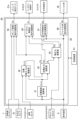
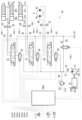
- FIG. 2 is a hydraulic circuit diagram showing the configuration of a hydraulic system of a working machine according to the first embodiment, and a diagram showing a control system of the hydraulic system. Note that in FIG. 2, the broken line indicates a control line.
- the hydraulic excavator is equipped with a hydraulic system 30 that hydraulically drives the lower traveling body 1, the upper rotating body 2, and the front working device 3 (see FIG. 1).
- the hydraulic system 30 includes a hydraulic pump 31 that is driven by a prime mover 32 such as an electric motor or an engine to discharge pressure oil, and a plurality of hydraulic actuators 5, 12, 20, 21 that are driven by the pressure oil discharged from the hydraulic pump 31. , 22.
- a prime mover 32 such as an electric motor or an engine to discharge pressure oil
- a plurality of hydraulic actuators 5, 12, 20, 21 that are driven by the pressure oil discharged from the hydraulic pump 31. , 22.
- the hydraulic actuators include a swing hydraulic motor 5 that swings the upper swing structure 2, and a boom cylinder 20 that moves the boom 17 and arm 18 of the front working device 3. Only the hydraulic circuit related to the arm cylinder 21 is shown. On the other hand, the hydraulic circuits related to the traveling hydraulic motor 12 that causes the lower traveling body 1 to travel and the bucket cylinder 22 that operates the bucket 19 of the front working device 3 are omitted.
- the hydraulic pump 31 is a variable displacement pump, and has a regulator 31a that adjusts the pump volume.
- the regulator 31a adjusts the pump volume according to commands from the control device 80.
- the prime mover 32 has a prime mover controller 32a that controls driving of the prime mover 32.
- the prime mover controller 32a is communicatively connected to the control device 80, and is configured to adjust the rotation speed of the prime mover 32 in accordance with commands from the control device 80.
- the prime mover controller 32a acquires the actual speed of the prime mover 32, which is a detected value of a speed sensor (not shown), and transmits drive information of the prime mover 32 including the acquired speed to the control device 80.
- the boom cylinder 20 and the arm cylinder 21 have first ports 20p1, 21p1 and second ports 20p2, 21p2 as a pair of input/output ports for supplying and discharging pressure oil, and have bottom chambers 20b, 21b and a rod as cylinder chambers. It has chambers 20r and 21r.
- the boom cylinder 20 and the arm cylinder 21 are configured to expand when pressure oil is supplied to the bottom chambers 20b and 21b, and to shorten when pressure oil is supplied to the rod chambers 20r and 21r.
- the swing hydraulic motor 5 has a first port 5a (the left port in FIG. 2) and a second port 5b (the right port in FIG. 2) as a pair of input/output ports for supplying and discharging pressure oil. are doing.
- the swing hydraulic motor 5 is configured, for example, to rotate clockwise when pressure oil is supplied to the first port 5a, and to rotate counterclockwise when pressure oil is supplied to the second port 5b.
- the hydraulic system 30 is configured such that pressure oil from the hydraulic pump 31 is supplied to the boom cylinder 20 via the first meter-in control valve 34 and the first directional control valve 35. There is. Further, pressure oil from the hydraulic pump 31 is supplied to the arm cylinder 21 via a second meter-in control valve 36 and a second directional control valve 37. Further, pressure oil from the hydraulic pump 31 is supplied to the swing hydraulic motor 5 via a third meter-in control valve 38 and a third directional control valve 39.
- the hydraulic pump 31 and each meter-in control valve 34 , 36 , 38 and each directional control valve 35 , 37 , 39 are connected via a discharge line 51 .
- the first directional control valve 35 and the boom cylinder 20 are connected via first actuator lines 53 and 54.
- the first actuator line 53 is connected to the bottom chamber 20b (first port 20p1) of the boom cylinder 20, and the first actuator line 54 is connected to the rod chamber 20r (second port 20p2) of the boom cylinder 20.
- the second directional control valve 37 and the arm cylinder 21 are connected via second actuator lines 55 and 56.
- the second actuator line 55 is connected to the bottom chamber 21b (first port 21p1) of the arm cylinder 21, and the second actuator line 56 is connected to the rod chamber 21r (second port 21p2) of the arm cylinder 21. ing.
- the third directional control valve 35 and the swing hydraulic motor 5 are connected via third actuator lines 57 and 58.
- the third actuator line 57 is connected to the first port 5a of the hydraulic swing motor 5, and the third actuator line 58 is connected to the second port 5b of the hydraulic swing motor 5.
- Each meter-in control valve 34, 36, 38 controls the flow rate of pressure oil (hereinafter sometimes referred to as meter-in flow rate) supplied from the hydraulic pump 31 to the corresponding hydraulic actuator 20, 21, 5.
- Each meter-in control valve 34, 36, 38 has an opening area (hereinafter referred to as a meter-in opening) whose position (stroke amount) is controlled according to a command (for example, a current command value) from the control device 80. ) is configured to change.
- each meter-in control valve 34, 36, 38 has the function of a check valve, and is fully closed when the discharge pressure of the hydraulic pump 31 is lower than the pressure on the side of each hydraulic actuator 20, 21, 5. It is controlled so that
- Each direction control valve 35, 37, 39 switches the flow direction of pressure oil supplied to the corresponding hydraulic actuator 20, 21, 5.
- the directional control valves 35 , 37 , 39 are connected to a hydraulic oil tank 41 via a tank line 52 so as to return the pressure oil discharged from the corresponding hydraulic actuators 20 , 21 , 5 to the hydraulic oil tank 41 . It is configured.
- Each directional control valve 35, 37, 39 has a meter-in passage that is a passage for communicating the discharge line 51 with the meter-in side (pressure oil supply side) of each hydraulic actuator 20, 21, 5, and each hydraulic actuator 20, It has a meter-out passage which is a passage for communicating the meter-out side (pressure oil discharge side) of 21 and 5 with the hydraulic oil tank 41.
- the directional control valves 35, 37, and 39 of this embodiment are meter-out control valves that control the flow rate of pressure oil discharged from the corresponding hydraulic actuators 20, 21, and 5 (hereinafter sometimes referred to as meter-out flow rate). It is configured to function as The opening area of the meter-in passage (hereinafter referred to as meter-in opening) of each directional control valve 35, 37, and 39 is controlled by the position (stroke amount) according to a command from the control device 80 (for example, a current command value).
- the opening area of the meter-out passage (hereinafter sometimes referred to as a meter-out opening) changes as the meter-out passage (hereinafter sometimes referred to as a meter-out opening) changes.
- the directional control valves 35, 37, and 39 are configured, for example, so that the meter-in openings are sufficiently larger than the opening control ranges of the meter-in control valves 34, 36, and 38. That is, the directional control valves 35, 37, and 39 do not have the function of controlling the meter-in flow rate, and only the meter-in control valves 34, 36, and 38 are configured to have the function of controlling the meter-in flow rate.
- a bleed-off valve 42 is provided on a line 59 that branches from the discharge line 51 and is connected to the hydraulic oil tank 41.
- the bleed-off valve 42 releases the pressure oil discharged from the hydraulic pump 31 to the hydraulic oil tank 41 according to its opening, and has a function of adjusting the discharge pressure of the hydraulic pump 31.
- the bleed-off valve 42 is configured so that its opening area changes by controlling its position (stroke amount) in accordance with a command (for example, a current command value) from the control device 80.
- a main relief valve 43 is provided on a relief line 60 that branches from the discharge line 51 and is connected to the hydraulic oil tank 41, which has a function of preventing overload of the hydraulic circuit.
- the main relief valve 43 defines the upper limit of the discharge pressure of the hydraulic pump 31, and is configured to open when the discharge pressure of the hydraulic pump 31 exceeds a set pressure.
- the discharge line 51 is provided with a discharge pressure sensor 61 that detects the discharge pressure of the hydraulic pump 31.
- the discharge pressure sensor 61 outputs a detection signal to the control device 80 according to the detected discharge pressure.
- the first actuator lines 53 and 54 have first actuator pressure sensors 62 and 63 (hereinafter referred to as first pressure sensors) that detect the pressure on the bottom chamber 20b side and the rod chamber 20r side of the boom cylinder 20, respectively.
- the second actuator lines 55 and 56 have second actuator pressure sensors 64 and 65 (hereinafter referred to as second pressure sensors) that detect the pressure on the bottom chamber 21b side and the rod chamber 21r side of the arm cylinder 21, respectively.
- the third actuator lines 57 and 58 are provided with third actuator pressure sensors 66 and 67 (hereinafter referred to as third pressure sensors) that detect the pressure on the first port 5a side and the second port 5b side of the swing hydraulic motor 5, respectively. ) is provided.
- the first to third pressure sensors 62 to 67 output detection signals corresponding to the detected pressures of the hydraulic actuators 20, 21, and 5 to the control device 80.
- the hydraulic excavator is equipped with a joystick 6 as an operating device for operating the hydraulic excavator, and a rotation speed dial 7 that indicates the rotation speed of the prime mover 32.
- the joystick 6 instructs the operation of the front working device 3 (driving the boom cylinder 20, arm cylinder 21, and bucket cylinder 22) and the turning operation of the upper revolving structure 2 (driving the swing hydraulic motor 5).
- the joystick 6 is of an electric type, and outputs an operation signal to the control device 80 according to the operation direction (specification of the pointing target) and the operation angle.
- the rotation speed dial 7 outputs an instruction signal according to the dial position (rotation speed) to the control device 80.
- the control device 80 receives operation signals from the joystick 6, instruction signals from the rotation speed dial 7, detection signals from the discharge pressure sensor 61 (discharge pressure of the hydraulic pump 31), and signals from the first to third pressure sensors 62 to 67. detection signals (pressure of hydraulic actuators 20, 21, 5), detection signals from the first to fifth attitude sensors 24 to 28 (attitude information and operation information of the upper revolving structure 2 and front working device 3), prime mover controller Drive information (including speed information) of the prime mover 32 is taken in from 32a.
- the control device 80 performs predetermined calculations based on these operation signals, instruction signals, detection signals, and drive information, and controls the regulator 31a of the hydraulic pump 31, the meter-in control valves 34, 36, 38, the directional control valves 35, 37, 39, outputs a command according to the calculation result to the bleed-off valve 42 and the prime mover controller 32a.
- FIG. 3 is a control block diagram of the control device for the work machine according to the first embodiment shown in FIG. 2.
- the control device 80 includes, as a hardware configuration, a storage device 81 consisting of a RAM, a ROM, etc., and a processing device 82 consisting of a CPU, an MPU, etc.
- the storage device 81 stores information necessary to control the pump volume of the hydraulic pump 31, the drive of each meter-in control valve 34, 36, 38, the drive of each directional control valve 35, 37, 39, and the drive of the bleed-off valve 42. Programs and various information are stored in advance.
- the processing device 82 reads programs and various information from the storage device 81 as appropriate, and implements various functions by executing processes according to the programs.
- the control device 80 controls the speed of the hydraulic actuators 20, 21, 5 according to the operation signal from the operation device 6, and maintains the pressure on the meter-in side of the hydraulic actuators 20, 21, 5 at a predetermined value or higher. It is intended to be controlled.
- the control device 80 of this embodiment performs speed control of the hydraulic actuators 20, 21, 5 by pressure control using pressure target values on the meter-in side and meter-out side of the hydraulic actuators 20, 21, 5.
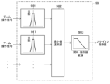
- the control device 80 includes, as control functional units, a target speed calculation unit 91, a target thrust/torque calculation unit 92, a target pressure calculation unit 93, an actual pressure calculation unit 94, a pump volume command calculation unit 95, and a meter-in control unit. It has a valve command calculation section 96, a directional control valve command calculation section 97, and a bleed-off valve command calculation section 98.
- the target speed calculation unit 91 calculates target speeds Vt and ⁇ t of each hydraulic actuator 20, 21, and 5 in accordance with the operation signal from the operation device 6.
- the calculated target speeds Vt and ⁇ t of each hydraulic actuator 20, 21, and 5 are output to the target thrust/torque calculation section 92 and the target pressure calculation section 93. Details of the calculation by the target speed calculation section 91 will be described later.
- the target thrust/torque calculation unit 92 calculates the thrust or torque of the hydraulic actuators 20, 21, 5 necessary to realize the target speeds Vt, ⁇ t of each hydraulic actuator 20, 21, 5 as a result of calculation by the target speed calculation unit 91. is calculated based on the driving states of the hydraulic actuators 20, 21, 22, and 5. Specifically, the operation signal from the operation device 6, the detection signal from each attitude sensor 24 to 28 (attitude information and operation information of the upper revolving body 2 and the front work device 3), and the calculation result of the target speed calculation unit 91. The target thrust Ft of the hydraulic cylinders 20 and 21 and the target torque Tt of the hydraulic motor 5 are calculated using the target speeds Vt and ⁇ t.
- the target thrust/torque calculation section 92 outputs the calculation results of the target thrust Ft and target torque Tt of the hydraulic actuators 20, 21, and 5 to the target pressure calculation section 93. Details of the calculation by the target thrust/torque calculation section 92 will be described later.
- the target pressure calculation section 93 calculates the target speeds Vt, ⁇ t of each hydraulic actuator 20, 21, 5 based on the calculation results of the target speed calculation section 91, and the target speeds Vt, ⁇ t of the hydraulic actuators 20, 21, 5 based on the calculation results of the target thrust/torque calculation section 92. Based on the target thrust Ft and target torque Tt, the meter-in target pressure Pit, which is the target value of the meter-in side pressure of the hydraulic actuators 20, 21, and 5, and the meter-out target pressure Pot, which is the target value of the meter-out side pressure, are determined. In addition to the calculation, the meter-in side of the hydraulic actuators 20, 21, and 5 is determined, and a meter-in flag fg corresponding to the determination result is set.
- the meter-in flag fg as a result of the determination is outputted to the actual pressure calculation unit 94, and the meter-in target pressure Pit of the hydraulic actuators 20, 21, and 5 as a result of the calculation is outputted to the pump volume command calculation unit 95 and the meter-in control valve command calculation unit 96. , outputs the calculated meter-out target pressure Pot of the hydraulic actuators 20, 21, and 5 to the directional control valve command calculating section 97. Details of the calculation by the target pressure calculation section 93 will be described later.
- the actual pressure calculation section 94 uses the detection signals of the first to third pressure sensors 62 to 67 (actual pressures of the hydraulic actuators 20, 21, 5) and the determination results of the target pressure calculation section 93 for the hydraulic actuators 20, 21, 5.
- the meter-in actual pressure Pia which is the actual pressure on the meter-in side of the hydraulic actuators 20, 21, and 5, and the meter-out actual pressure Poa, which is the actual pressure on the meter-out side, of the hydraulic actuators 20, 21, and 5 are calculated based on the meter in flag fg.
- the calculated meter-in actual pressure Pia of the hydraulic actuators 20, 21, 5 is output to the meter-in control valve command calculating section 96, and the calculated meter-out actual pressure Poa of the hydraulic actuators 20, 21, 5 is output to the directional control valve command calculation. output to section 97. Details of the calculation by the actual pressure calculation section 94 will be described later.
- the pump volume command calculation unit 95 calculates the instruction signal from the rotation speed dial 7 (required rotation speed of the prime mover 32), the detection signal from the discharge pressure sensor 61 (actual discharge pressure of the hydraulic pump 31), and the calculation by the target pressure calculation unit 93. Based on the resulting meter-in target pressures Pit of the hydraulic actuators 20, 21, and 5, a volume command value Cq for commanding the pump volume of the hydraulic pump 31 is calculated. The volume command value Cq resulting from the calculation is output to the regulator 31a of the hydraulic pump 31. Details of the calculation by the pump volume command calculation unit 95 will be described later.
- the meter-in control valve command calculation section 96 calculates the operation signal from the operating device 6, the meter-in target pressure Pi of the hydraulic actuators 20, 21, 5 based on the calculation result of the target pressure calculation section 93, and the meter-in actual pressure of the calculation result of the actual pressure calculation section 94.
- a meter-in command value Ci for commanding the driving of the meter-in control valves 34, 36, and 38 is calculated based on the pressure Pia.
- the meter-in command value Ci resulting from the calculation is output to the meter-in control valves 34, 36, and 38. Details of the calculation by the meter-in control valve command calculation section 96 will be described later.
- the directional control valve command calculation unit 97 receives the operation signal from the operating device 6, the meter-out target pressure Pot of the hydraulic actuators 20, 21, 5 based on the calculation result of the target pressure calculation unit 93, and the meter output of the calculation result of the actual pressure calculation unit 94.
- a meter-out command value Cd for commanding the drive of each directional control valve 35, 37, 39 is calculated based on the actual out pressure Poa.
- the meter-out command value Cd resulting from the calculation is output to each direction control valve 35, 37, 39. Details of the calculation by the directional control valve command calculation section 97 will be described later.
- the bleed-off valve command calculation unit 98 calculates a bleed-off command value Cb that commands the drive of the bleed-off valve 42 in response to an operation signal from the operating device 6.
- the bleed-off command value Cb resulting from the calculation is output to the bleed-off valve 42. Details of the calculation by the bleed-off valve command calculation section 98 will be described later.
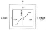
- FIG. 4 is a control block diagram of the target speed calculating section in the control device according to the first embodiment shown in FIG. 3.
- the target speed calculating unit 91 calculates the target speeds Vt and ⁇ t of each hydraulic actuator based on the operation signal from the operating device 6 by referring to the table 911 shown in FIG.
- the operation signal of the operation device 6 is 0% when not operated, and changes from -100% to +100% depending on the operation direction and amount of operation.
- the hydraulic actuator is a hydraulic cylinder
- the speed in the extension direction of the hydraulic cylinder is set as positive
- the speed in the shortening direction is set as negative.
- the hydraulic actuator is a hydraulic motor
- the speed of right rotation of the hydraulic motor is positive
- the speed of left rotation of the hydraulic motor is negative.
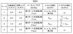
- FIG. 5 is a control block diagram of the target thrust/torque calculation section in the control device according to the first embodiment shown in FIG. 3.
- the target thrust/torque calculation section 92 calculates the operating state of the front working device 3 (driven body) that can achieve the target speed Vt of the hydraulic cylinders 20, 21, 22, which is the calculation result of the target speed calculating section 91, as a front working device. This calculation takes into consideration the inertia (self-weight) of 3. Specifically, as shown in FIG. 5, the target thrust/torque calculation section 92 includes a conversion section 921A, a rate restriction section 922, a target angular acceleration calculation section 923, a required torque calculation section 924, a deviation calculation section 925, and a feedback calculation section. 926, a torque limiter 927, an absolute torque limiter 928, an adder 929, and a converter 921B.
- the conversion unit 921A converts the target speed Vt of the hydraulic cylinders 20, 21, 22, which is the calculation result of the target speed calculation unit 91, into the angular velocity of each component 17, 18, 19 of the front working device 3 or their joint parts 18a, 19a. It is converted into .
- the converter 921A is, for example, a Jacobian inverse matrix that converts the cylinder coordinate system of the hydraulic cylinders 20, 21, 22 to the angular coordinate system of the joint parts 18a, 19a.
- the converter 921A outputs the angular velocity of the calculation result to the rate limiter 922.
- the rate limiting unit 922 determines the rate of change (rate) of increase and decrease per unit time with respect to the angular velocity of the joint parts 18a, 19a (boom 17, arm 18, bucket 19) of the front working device 3 as a result of the calculation by the converting unit 921A. ).
- the rate limiting unit 922 outputs a target angular velocity obtained by limiting the rate of the angular velocity calculated by the converting unit 921A to the target angular acceleration calculating unit 923 and the deviation calculating unit 925.
- the rate limit can be set to a predetermined value or changed according to conditions.
- the target angular acceleration calculation unit 923 calculates the target angular acceleration of the joint parts 18a, 19a (boom 17, arm 18, bucket 19) of the front working device 3 by time-differentiating the target angular velocity output from the rate limiting unit 922. calculate.
- the target angular acceleration resulting from the calculation is output to the required torque calculation section 924.
- the required torque calculation unit 924 calculates the joint parts 18a and 19a (boom 17, arm 18, bucket 19 ), the joint parts 18a, 19a (boom 17, arm 18, bucket 19) of the front working device 3 are calculated based on the calculation results of the target angular acceleration calculation unit 923.
- the required torque ⁇ which is the torque required to achieve a driving state in which a certain target angular acceleration can be achieved, is calculated.
- the required torque calculation unit 924 calculates the required torque ⁇ using the following equation of motion for rotational motion.
- ⁇ is the actual angle of the joint parts 18a and 19a of the boom 17, arm 18, and bucket 19 of the front working device 3, and ⁇ with a dot symbol on the upper side is the joint part 18a and 19a of the boom 17, arm 18, and bucket 19.
- the actual angular velocity ⁇ t with a double dot symbol above indicates the target angular acceleration of the joint portions 18a and 19a of the boom 17, arm 18, and bucket 19.
- the posture information and motion information of the posture sensors 25 to 28 are substituted for ⁇ and ⁇ with a dot symbol, and the target of the calculation result of the target angular acceleration calculation unit 923 is substituted for ⁇ t with a double dot symbol. Substitute the angular acceleration. Thereby, the required torque ⁇ is calculated. The required torque ⁇ resulting from the calculation is output to the adding section 929.
- the deviation calculation unit 925 calculates the target angular velocity output from the rate limiting unit 922 and the actual angular velocity of the joint parts 18a and 19a (boom 17, arm 18, bucket 19) of the front working device 3, which is the detected value of the attitude sensors 25 to 28. It calculates the deviation from the The angular velocity deviation resulting from the calculation is output to the feedback calculation section 926.
- the feedback calculation unit 926 calculates a feedback correction value for the target torque by feedback control such as PI control or PID control based on the angular velocity deviation that is the calculation result of the deviation calculation unit 925.
- the feedback correction value of the calculation result is output to the torque absolute value limiting section 928.
- the torque limiting section 927 uses a table stored in advance in the storage device 81 to control the joint portions 18a and 19a of the respective structural members 17, 18, and 19 of the front working device 3 in accordance with the operation signal from the operating device 6. It outputs the torque limit value.
- the torque limit value is output to the torque absolute value limiter 928.
- the torque absolute value limiter 928 limits the absolute value of the feedback correction value of the calculation result of the feedback calculator 926 using the torque limit value from the torque limiter 927.
- the feedback correction value whose absolute value is limited by the torque limit value is output to the adding section 929.
- the adding unit 929 adds the feedback correction value output from the torque absolute value limiting unit 928 to the required torque ⁇ calculated by the required torque calculating unit 924, thereby adjusting the joint parts 18a, 19a ( The target torques of the boom 17, arm 18, and bucket 19) are calculated.
- the target torque resulting from the calculation is output to the converter 921B.
- the conversion unit 921B converts the target torque of the joint parts 18a, 19a (boom 17, arm 18, bucket 19) of the front working device 3 from the addition unit 929 into the target thrust force Ft of the hydraulic cylinders 20, 21, 22.
- the converter 921B is an inverse calculation of the converter 921A, and is, for example, a Jacobian matrix that converts the angular coordinate system of the joint parts 18a, 19a to the cylinder coordinate system of the hydraulic cylinders 20, 21, 22.
- the target speed that is the calculation result of the target speed calculation unit 91 is not the hydraulic cylinders 20, 21, and 22 that operate the front working device 3 but the swing hydraulic motor 5 that swings the upper swing structure 2, the above-mentioned The functional units 921A, 921B to 929 are changed as follows.
- the conversion unit 921A converts the target speed ⁇ t of the swing hydraulic motor 5, which is the calculation result of the target speed calculation unit 91, into the swing speed (angular velocity) of the upper rotating structure 2.
- the conversion unit 921A is, for example, a reduction ratio of the rotation of the upper rotating body 2 to the rotation of the swing hydraulic motor 5.
- the conversion unit 921B is an inverse calculation of the conversion unit 921A, and converts the swing target torque of the upper revolving structure 2 into the target torque of the swing hydraulic motor 5.
- the required torque calculation unit 924 uses the equation of motion of the rotational motion of the upper rotating body 2 in place of the equation of motion of the rotational motion of the joint portions 18a and 19a of the front working device 3. That is, the required torque calculation unit 924 calculates the calculation result of the target angular acceleration calculation unit 923 based on the actual turning angle (actual angle) and the actual turning speed (actual angular velocity) of the upper rotating structure 2, which are the detected values of the attitude sensor 24.
- the required torque ⁇ required for the upper revolving superstructure 2 to be in a driving state in which it can achieve the target angular acceleration is calculated.
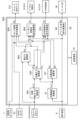
- FIG. 6 is a table showing an example of a calculation method (in the case of a hydraulic cylinder) of the target pressure calculation section in the control device according to the first embodiment shown in FIG.
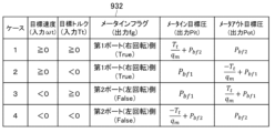
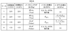
- FIG. 7 is a table showing another example (in the case of a hydraulic motor) of the calculation method of the target pressure calculation section in the control device according to the first embodiment shown in FIG.
- the target pressure calculation section 93 calculates the target speed Vt of the hydraulic actuators 5, 20, 21, 22 from the target speed calculation section 91, the positive/negative of ⁇ t, and the target thrust/torque calculation section 92 of the hydraulic actuators 5, 20, 21, 22.
- the situations of the hydraulic actuators 5, 20, 21, and 22 are classified based on the sign of the target thrust Ft and the target torque Tt. Furthermore, depending on the case, the pressure oil supply side of the hydraulic actuators 5, 20, 21, 22 is determined and the meter flag fg is set, and the pressure oil supply side of the hydraulic actuators 5, 20, 21, 22 is determined.
- a meter-in target pressure, which is a target pressure, and a meter-out target pressure, which is a target pressure on the pressure oil discharge side, are calculated.
- a table 931 is used when the hydraulic actuator is the hydraulic cylinders 20, 21, and 22, and a table 932 is used when the hydraulic actuator is the hydraulic motor 5.
- Case 1 is defined as a case where the target thrust force Ft or target torque Tt of the hydraulic actuators 20, 21, and 5 is positive (more precisely, 0 or more).
- Case 2 is a case in which the target speeds Vt and ⁇ t are positive and the target thrust Ft or target torque Tt is negative.
- Case 3 is a case where the target speeds Vt and ⁇ t are negative and the target thrust Ft or target torque Tt is positive (more precisely, 0 or more).
- Case 4 is a case in which the target speeds Vt and ⁇ t are negative, and the target thrust Ft or target torque Tt is negative.
- the hydraulic actuators are hydraulic cylinders 20 and 21, the thrust in the extension direction of the hydraulic cylinders 20 and 21 is positive, and the thrust in the contraction direction is negative.
- the hydraulic actuator is the hydraulic motor 5
- the torque in the clockwise rotation direction of the hydraulic motor 5 is positive, and the torque in the counterclockwise rotation direction is negative.
- a table 931 shown in FIG. 6 is used.
- the meter flag is set to the bottom chambers 20b and 21b of the hydraulic cylinders 20 and 21.
- the cylinder chamber on the meter-out side has a lower pressure than the cylinder chamber on the meter-in side. Therefore, the meter-out target pressure Pot is set to a minimum pressure Pbf2 that does not cause cavitation in the cylinder chamber on the meter-out side.
- the lowest pressure Pbf2 is, for example, about 1 MPa.
- the meter-in target pressure Pit is obtained by dividing the sum of the meter-out side thrust (the thrust generated by the set pressure Pbf2) and the target thrust Ft by the cross-sectional area of the meter-in side cylinder chamber.
- the cylinder chambers on the meter-in side are bottom chambers 20b and 21b
- the cylinder chambers on the meter-out side are rod chambers 20r and 21r.
- the meter-in target pressure Pit is calculated from the following equation.
- Sb represents the cross-sectional area of the hydraulic cylinders 20 and 21 on the bottom chambers 20b and 21b side
- Sr represents the cross-sectional area of the rod chambers 20r and 21r side
- Ft represents the target thrust of the hydraulic cylinders 20 and 21.
- the meter flag is set to the bottom chambers 20b and 21b side.
- the cylinder chambers on the meter-in side of the hydraulic cylinders 20 and 21 have a lower pressure than the cylinder chambers on the meter-out side. Therefore, the meter-in target pressure Pit is set to a predetermined pressure Pbf1 that does not cause cavitation in the cylinder chamber on the meter-in side.
- the predetermined pressure Pbf1 is a pressure higher than the lowest pressure Pbf2 set in case 1, and is, for example, about 3 MPa.
- the meter-out target pressure Pot is obtained by subtracting the target thrust Ft from the meter-in thrust (the thrust generated by the predetermined pressure Pbf1) and dividing the value by the cross-sectional area of the meter-out cylinder chamber.
- the cylinder chambers on the meter-in side are bottom chambers 20b, 21b, and the cylinder chambers on the meter-out side are rod chambers 20r, 21r. Therefore, the meter-out target pressure Pot is calculated from the following equation.
- the meter flag is set on the rod chambers 20r, 21r side of the hydraulic cylinders 20, 21.
- the cylinder chamber on the meter-in side has a lower pressure than the cylinder chamber on the meter-out side. Therefore, similarly to Case 2, the meter-in target pressure Pit is set to a predetermined pressure Pbf1 that does not cause cavitation in the cylinder chamber on the meter-in side.
- the meter-out target pressure Pot is obtained by dividing the sum of the meter-in side thrust (the thrust generated by the predetermined pressure Pbf1) and the target thrust Ft by the cross-sectional area of the meter-out side cylinder chamber.
- the meter-out target pressure Pot is calculated from the following equation.
- the meter flag is set to the rod chambers 20r and 21r side.
- the cylinder chamber on the meter-out side has a lower pressure than the cylinder chamber on the meter-in side. Therefore, similarly to Case 1, the meter-out target pressure Pot is set to the lowest pressure Pbf2.
- the meter-in target pressure Pit is obtained by dividing the value obtained by subtracting the target thrust Ft from the meter-out side thrust (the thrust generated by the lowest pressure Pbf2) by the cross-sectional area of the meter-in side cylinder chamber.
- the meter-in target pressure Pit is calculated from the following equation.
- the target pressure calculation unit 93 outputs "True” when the meter infrastructure flag is the bottom chambers 20b and 21b, and outputs "False” when the meter infrastructure flag is the rod chambers 20r and 21r. is configured to do so. Also, the initial value of the meter flag is set to "True”. Note that it is also possible to reverse the relationship between "True” and “False” of the meter flag.
- the hydraulic actuator is the hydraulic motor 5
- a table 932 shown in FIG. 7 is used.
- the meter flag is set to the first port 5a (clockwise rotation) side.
- the meter-out side port of the hydraulic motor 5 has a lower pressure than the meter-in side port. Therefore, similarly to the case of the hydraulic cylinders 20 and 21, the meter-out target pressure Pot is set to the lowest pressure Pbf2 at which cavitation does not occur on the meter-out side of the hydraulic motor 5.
- the meter-in target pressure Pit is obtained by the sum of the calculation result obtained by dividing the target torque Tt by the pump volume qm stored in advance in the storage device 81 and the pressure on the meter-out side of the hydraulic motor 5, that is, the set minimum pressure Pbf2. . That is, the meter-in target pressure Pit is calculated from the following equation.
- case 2 similarly to case 1, set the meter flag to the first port 5a (clockwise rotation) side.
- the meter-in side port has a lower pressure than the meter-out side port. Therefore, the meter-in target pressure Pit is set to a predetermined pressure Pbf1 that does not cause cavitation on the port side of the meter-in. Since the meter-in side port of the hydraulic motor 5 has a high risk of cavitation occurring on the suction side, the predetermined pressure Pbf1 is set to a pressure higher than the minimum pressure Pbf2 set in case 1, as in the case of the hydraulic cylinders 20 and 21. do.
- the meter-out target pressure Pot is obtained by subtracting the calculation result obtained by dividing the target torque Tt by the pump volume qm from the pressure on the meter-in side of the hydraulic motor 5, that is, the set predetermined pressure Pbf1. That is, the meter-out target pressure Pot is calculated from the following equation.
- the meter-in target pressure Pit is set to a predetermined pressure Pbf1 that does not cause cavitation on the meter-in port side.
- the meter-out target pressure Pot is obtained by the sum of the calculation result obtained by dividing the target torque Tt by the pump volume qm and the pressure on the meter-in side of the hydraulic motor 5, that is, the set predetermined pressure Pbf1. That is, the meter-out target pressure Pot is calculated from the following equation.
- the meter flag is set to the second port 5b (left rotation) side.
- the meter-out side port has a lower pressure than the meter-in side port. Therefore, similarly to Case 1, the meter-out target pressure Pot is set to the lowest pressure Pbf2.
- the meter-in target pressure Pit is obtained by subtracting the calculation result obtained by dividing the target torque Tt by the pump volume qm from the pressure on the meter-out side of the hydraulic motor 5, that is, the set minimum pressure Pbf2. That is, the meter-in target pressure Pit is calculated from the following equation.
- FIG. 8 is a control block diagram of the actual pressure calculating section in the control device according to the first embodiment shown in FIG.
- the actual pressure calculation unit 94 has functional units of a meter-in selection unit 941, a NOT calculation unit 942, and a meter-out selection unit 943, as shown in FIG. 8, for example.
- the meter-in selection unit 941 selects the detection signals of the first to second pressure sensors 62 to 65 (the bottom chambers 20b and 21b of the hydraulic cylinders 20 and 21 and the rod chamber 20r, The actual pressure on the meter-in side of the hydraulic cylinders 20 and 21 is output based on the meter flag fg as a result of processing by the target pressure calculating section 93. That is, when the meter flag fg is "True", the actual pressure in the bottom chambers 20b, 21b of the hydraulic cylinders 20, 21 is output as the actual pressure on the meter-in side. On the other hand, when the meter flag fg is "False", the actual pressure in the rod chambers 20r, 21r of the hydraulic cylinders 20, 21 is output as the actual pressure on the meter-in side.
- the detection signals of the third pressure sensors 66 and 67 (the actual pressures on the first port 5a side and the second port 5b side of the swing hydraulic motor 5) and the target pressure calculation section 93 are used.
- the actual pressure on the meter-in side of the hydraulic motor 5 is output based on the meter in flag fg as a result of the processing. That is, when the meter in flag fg is "True”, the actual pressure on the first port 5a side of the swing hydraulic motor 5 is output as the actual pressure on the meter-in side.
- the meter infrastructure fgg is "False"
- the actual pressure on the second port 5b side of the swing hydraulic motor 5 is output as the actual pressure on the meter-in side.
- the NOT calculation unit 942 inverts the meter in flag fg as a result of processing by the target pressure calculation unit 93 and inputs it to the meter out selection unit 943. That is, when the meter in flag fg is "True”, “False” is input to the meter out selection section 943. On the other hand, when the meter in flag fg is "False”, “True” is input to the meter out selection section 943.
- the meter-out selection unit 943 selects the detection signals of the first to second pressure sensors 62 to 65 (the bottom chambers 20b and 21b of the hydraulic cylinders 20 and 21 and the rod chamber 20r). , 21r) and the processing result of the NOT calculation unit 942 (inversion of the meter in flag fg), the actual pressure on the meter-out side of the hydraulic cylinders 20 and 21 is output. Since the meter-out selection section 943 receives the result of the inversion processing of the meter-in flag fg by the NOT calculation section 942, it outputs the actual pressure in the cylinder chamber that is different from the meter-in selection section 941, that is, the actual pressure on the meter-out side.
- the hydraulic actuator is the hydraulic motor 5
- the detection signals of the third pressure sensors 66 and 67 (the actual pressures on the first port 5a side and the second port 5b side of the swing hydraulic motor 5) and the NOT calculation unit 942 Based on the processing results, the actual pressure on the meter-out side of the hydraulic motor 5 is output.
- FIG. 9 is a control block diagram of the pump volume command calculation section in the control device according to the first embodiment shown in FIG. 3.
- the pump volume command calculation unit 95 includes the following functional units: a maximum value selection unit 951, an addition unit 952, a deviation calculation unit 953, a feedback calculation unit 954, a target pump volume calculation unit 955, and a command conversion unit 956. There is.
- the maximum value selection section 951 selects the maximum value of the meter-in target pressures of all the hydraulic actuators 20, 21, and 5 output from the target pressure calculation section 93, and adds the maximum value of the selected meter-in target pressures to the addition section 952. Output to.
- the addition unit 952 calculates the target discharge pressure of the hydraulic pump 31 by adding the buffer pressure Pbf3 to the maximum value of the meter-in target pressures of the hydraulic actuators 20, 21, and 5 output from the maximum value selection unit 951. .
- the buffer pressure Pbf3 is stored in advance in the storage device 81 and is, for example, 1 MPa.
- the buffer pressure Pbf3 takes into consideration the pressure loss that occurs between the hydraulic pump 31 and the hydraulic actuators 20, 21, and 5. This is intended to improve the controllability of the meter-in flow rate control of the hydraulic actuators 20, 21, and 5 by increasing the target discharge pressure of the hydraulic pump 31 by the pressure loss.
- the calculated target discharge pressure of the hydraulic pump 31 is output to the deviation calculating section 953.
- the deviation calculation unit 953 calculates the deviation between the target discharge pressure of the hydraulic pump 31 from the addition unit 952 and the actual discharge pressure of the hydraulic pump 31, which is the detected value of the discharge pressure sensor 61.
- the deviation of the calculation result is output to the feedback calculation section 954.
- the feedback calculation unit 954 calculates the target flow rate of the hydraulic pump 31 as a control amount by feedback control such as PI control or PID control based on the discharge pressure deviation of the hydraulic pump 31 which is the calculation result of the deviation calculation unit 953.
- the target flow rate of the hydraulic pump 31 as a feedback control amount of the calculation result is output to the target pump volume calculation section 955.
- the target pump volume calculation section 955 calculates the hydraulic pressure by dividing the pump target flow rate, which is the calculation result of the feedback calculation section 954, by the required rotation speed of the prime mover 32 (for example, converted based on the instruction signal from the rotation speed dial 7). A target pump volume of the pump 31 is calculated. The target pump volume of the hydraulic pump 31 resulting from the calculation is output to the command conversion unit 956.
- the command conversion unit 956 converts the target pump volume of the hydraulic pump 31, which is the calculation result of the target pump volume calculation unit 955, into a command value (for example, a drive current command value to a pump control solenoid (not shown)).
- the command conversion unit 956 outputs a command value to the regulator 31a of the hydraulic pump 31.
- FIG. 10 is a control block diagram of a meter-in control valve command calculation section in the control device according to the first embodiment shown in FIG.
- the meter-in control valve command calculation unit 96 has the following functional units: a meter-in opening conversion unit 961, a deviation calculation unit 962, a feedback calculation unit 963, a meter-in target opening calculation unit 964, and a command conversion unit 965.
- the meter-in opening converter 961 calculates the required opening values of the meter-in control valves 34, 36, and 38 based on the operation signal from the operating device 6.
- the calculated required opening values of the meter-in control valves 34, 36, and 38 are output to the meter-in target opening calculating section 964.
- the deviation calculation section 962 calculates the meter-in target pressures of the hydraulic actuators 20, 21, and 5, which are the calculation results of the target pressure calculation section 93, and the meter-in side actual pressures of the hydraulic actuators 20, 21, and 5, which are the calculation results of the actual pressure calculation section 94. Calculate the deviation from the pressure. The pressure deviation resulting from the calculation is output to the feedback calculation section 963.
- the feedback calculation unit 963 controls the meter-in control valves 34, 36, 38 by feedback control such as PI control or PID control based on the pressure deviation on the meter-in side of the hydraulic actuators 20, 21, 5, which is the calculation result of the deviation calculation unit 962. This is to calculate a feedback correction value for the target aperture.
- the feedback correction value of the calculation result is output to the meter-in target aperture calculation section 964.
- the meter-in target opening calculation unit 964 adds the feedback correction value, which is the calculation result of the feedback calculation unit 963, to the opening request value, which is the calculation result of the meter-in opening conversion unit 961, to adjust the meter-in control valves 34, 36, and 38. Calculate the target aperture.
- the calculated target openings of the meter-in control valves 34, 36, and 38 are output to the command conversion section 965.
- the command conversion unit 965 converts target openings of the meter-in control valves 34, 36, and 38, which are the calculation results of the meter-in target opening calculation unit 964, into command values (for example, current command values) for driving the meter-in control valves 34, 36, and 38. ).
- the command converter 965 outputs a current command value to the solenoids of the meter-in control valves 34, 36, and 38.
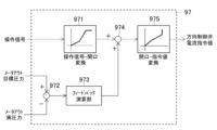
- FIG. 11 is a control block diagram of the directional control valve command calculating section in the control device according to the first embodiment shown in FIG.
- the directional control valve command calculation unit 97 calculates the meter-out target of the hydraulic actuators 20, 21, 5 obtained from the operation signal from the operation device 6 and the target speed Vt ( ⁇ t) according to the operation signal of the operation device 6.
- a meter-out command value Cd for controlling the directional control valves 35, 37, and 39 is calculated based on the pressure Pot.
- the directional control valve command calculation unit 97 has the following functional units: a meter-out opening conversion unit 971, a deviation calculation unit 972, a feedback calculation unit 973, a meter-out target opening calculation unit 974, and a command conversion unit 975.
- the meter-out opening conversion unit 971 calculates the required meter-out opening values of the directional control valves 35, 37, and 39 based on the operation signal of the operating device 6.
- the calculated meter-out opening request values for the directional control valves 35, 37, and 39 are output to the meter-out target opening calculating section 974.
- the deviation calculation section 972 calculates the meter-out target pressures of the hydraulic actuators 20, 21, and 5, which are the calculation results of the target pressure calculation section 93, and the meter-out side of the hydraulic actuators 20, 21, and 5, which are the calculation results of the actual pressure calculation section 94. Calculate the deviation from the actual pressure. The pressure deviation resulting from the calculation is output to the feedback calculation section 973.
- the feedback calculation unit 973 controls the direction control valves 35, 37, 39 by feedback control such as PI control or PID control based on the pressure deviation on the meter-out side of the hydraulic actuators 20, 21, 5, which is the calculation result of the deviation calculation unit 972.
- the feedback correction value of the meter-out target aperture is calculated.
- the feedback correction value of the calculation result is output to the meter-out target aperture calculation section 974.
- the meter-out target opening calculation unit 974 adds the feedback correction value, which is the calculation result of the feedback calculation unit 973, to the meter-out opening request value, which is the calculation result of the meter-out opening conversion unit 971. 37 and 39, the meter-out target apertures are calculated. The meter-out target openings of the directional control valves 35, 37, and 39 as a result of the calculation are output to the command conversion section 975.
- the command conversion unit 975 converts the meter-out target openings of the directional control valves 35, 37, 39, which are the calculation results of the meter-out target opening calculation unit 974, into command values for driving the directional control valves 35, 37, 39 (for example, current command value).
- the command conversion unit 975 outputs a current command value to the solenoids of the directional control valves 35, 37, and 39.
- FIG. 12 is a control block diagram of the bleed-off valve command calculation section in the control device according to the first embodiment shown in FIG.
- the bleed-off valve command calculation unit 98 has the functional units of a bleed-off opening conversion unit 981, a minimum value selection unit 982, and a command conversion unit 983.
- the bleed-off opening conversion unit 981 calculates the required opening value of the bleed-off valve 42 based on the operation signal of each operation (boom operation, arm operation, swing operation, etc.) from the operating device 6.
- the required opening value of the bleed-off valve 42 for each operation based on the calculation result is outputted to the minimum value selection section 982, respectively.
- the minimum value selection unit 982 selects the minimum value from among all the required opening values of the bleed-off valves 42 as the calculation results of the bleed-off opening conversion unit 981.
- the minimum value of the selected opening request for the bleed-off valve 42 is output to the command conversion unit 983 as the target opening of the bleed-off valve 42.
- the command conversion unit 983 converts the target opening of the bleed-off valve 42 output from the minimum value selection unit 982 into a command value (for example, a current command value) for driving the bleed-off valve 42.
- the command conversion unit 983 outputs a current command value to the solenoid of the bleed-off valve 42.
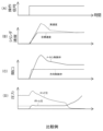
- FIG. 13 is a diagram showing changes in the operating states of the hydraulic cylinder, meter-in control valve, and directional control valve with respect to arm crowd operation in a known work machine as a comparative example with respect to the work machine according to the first embodiment.
- Graphs (A) to (D) shown in FIG. 13 show graphs when a single operation of the arm cloud is input to the operating device 6 while the front working device 3 is maintained in the air.
- Graph (A) shows the change over time of the operation signal for single operation of the arm cloud.
- Graph (B) shows changes in the target speed and actual speed of the hydraulic cylinder (arm cylinder 21) with respect to the operation signal of the operation device 6.
- Graph (C) shows changes in the openings of the meter-in control valve and the direction control valve in response to the operation signal of the operation device 6.
- Graph (D) shows changes in the pressure in the bottom chamber (bottom pressure) and the pressure in the rod chamber (rod pressure) of the arm cylinder with respect to the operation signal of the operation device 6.
- the opening of the meter-in control valve that controls the meter-in flow rate of the arm cylinder is made larger than under normal control.
- the bottom pressure of the arm cylinder is maintained higher than the pressure at which cavitation occurs.
- the driving speed of the arm cylinder becomes faster than the target speed according to the operation of the operating device, as shown by the broken line in graph (B).
- the driving speed of the arm cylinder becomes faster than the target speed according to the operation of the operating device, as shown by the broken line in graph (B).
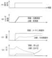
- FIG. 14 is a diagram showing changes in the operating states of the hydraulic cylinder, meter-in control valve, and directional control valve in response to arm cloud operation in the work machine according to the first embodiment.
- Graphs (A) to (D) shown in FIG. 14 are similar to the graph shown in FIG. 13 when a single operation of the arm cloud is input to the operating device 6 while the front working device 3 is maintained in the air. It shows the waveforms of changes in the driving states of the hydraulic cylinder, meter-in control valve, and directional control valve in the case of
- the control device 80 calculates a target speed Vt of the arm cylinder 21 according to the operation signal, and sets a target speed Vt that satisfies the target speed Vt as a result of the calculation. Calculate thrust force Ft. Further, a meter-in target pressure Pit and a meter-out target pressure Pot of the arm cylinder 21 are calculated according to the sign of the target speed Vt and the target thrust Ft of the calculation results.
- a state corresponding to case 2 of table 931 shown in FIG. 6 is passed.
- the pressure target value (meter-in target pressure Pit) of the bottom chamber 21b of the arm cylinder 21 is set to a predetermined value Pbf1 that can prevent the occurrence of cavitation, while the target pressure value (meter-out target pressure Pot) of the rod chamber 21r is set. is set according to the target thrust Ft that can achieve the target speed Vt and the predetermined value Pbf1 on the meter-in side.
- the control device 80 determines the pump volume of the hydraulic pump 31, the opening of the meter-in control valve 36, and the meter-out opening of the direction control valve 37 based on the calculated meter-in target pressure Pit and meter-out target pressure Pot of the arm cylinder 21. Control. Specifically, while controlling the meter-out opening of the direction control valve 37 so that the arm cylinder 21 reaches the target speed Vt according to the operation of the operating device 6, the pressure ( The opening of the meter-in control valve 36 and the pump volume of the hydraulic pump 31 are controlled so that the bottom pressure) becomes equal to or higher than the pressure value Pbf1 (meter-in target pressure Pit) at which cavitation can be prevented.
- Pbf1 meter-in target pressure Pit
- the hydraulic excavator (work machine) includes hydraulic actuators 20, 21, which operate driven bodies 17, 18, 19, 2 by being driven by supplying and discharging pressure oil (working fluid). 22, 5 (hydraulic actuator), a hydraulic pump 31 (pump) that supplies pressure oil (working fluid) to the hydraulic actuators 20, 21, 22, 5 (hydraulic actuator), and hydraulic pump 31 (pump).
- Meter-in control valves 34, 36, 38 that can control the flow rate of pressure oil (working fluid) supplied from the hydraulic actuators 20, 21, 22, 5 (fluid pressure actuators) to the hydraulic actuators 20, 21, 22, 5
- Directional control valves 35, 37, 39 as meter-out control valves that can control the flow rate of pressure oil (working fluid) discharged from (fluid pressure actuator), hydraulic actuators 20, 21, 22, 5 (fluid pressure actuator) ), and control for controlling the hydraulic pump 31 (pump), meter-in control valves 34, 36, 38, and directional control valves 35, 37, 39 (meter-out control valves).
- a device 80 is provided.
- the control device 80 calculates target speeds Vt, ⁇ t of the hydraulic actuators 20, 21, 22, 5 (fluid pressure actuators) according to the operation signal from the operating device 6,
- the target thrust Ft or target torque Tt of the hydraulic actuators 20, 21, 22, 5 (fluid pressure actuators) is calculated based on the driving state of the hydraulic actuators), and the target speed Vt of the calculation result, the sign of ⁇ t is the target of the calculation result. If the positive or negative of the thrust force Ft or the target torque Tt is different, the speed of the hydraulic actuators 20, 21, 22, 5 (fluid pressure actuators) is adjusted based on the operation signal from the operating device 6.
- the hydraulic pump 31 (pump) or the meter-in control valves 34, 36 are controlled by the meter-out control valve (meter-out control valve), and the pressure on the meter-in side of the hydraulic actuators 20, 21, 22, 5 (fluid pressure actuators) is equal to or higher than a predetermined value. , 38.
- the driving speed of the hydraulic actuators 20, 21, 22, 5 is controlled by the operating device 6.
- the pressure on the meter-in side of the hydraulic actuators 20, 21, 22, 5 is controlled to exceed a predetermined value while being controlled by the directional control valves 35, 37, 39 (meter-out control valves) according to the operation. Since at least one of the hydraulic pump 31 (pump) or the meter-in control valves 34, 36, and 38 is controlled, by setting the predetermined value to a value that can avoid occurrence of cavitation, the hydraulic pressure can be adjusted according to the operation of the operating device 6. Cavitation of the hydraulic actuators 20, 21, 22, 5 (hydraulic actuators) can be prevented while realizing speed control of the actuators 20, 21, 22, 5 (hydraulic actuators).
- the hydraulic excavator (work machine) also includes a discharge pressure sensor 61 (first pressure sensor) that detects the discharge pressure of the hydraulic pump 31 (pump), and hydraulic actuators 20, 21, 22, 5 ( actuator pressure sensors 62 to 67 (second pressure sensors) that detect pressure on the meter-in side of the fluid pressure actuator).
- the control device 80 is configured to calculate the target thrust Ft or the target torque Tt based on the calculated target speeds Vt and ⁇ t.
- the control device 80 controls the pressure on the meter-in side of the hydraulic actuators 20, 21, 22, and 5 (fluid pressure actuators) when the sign of the target speed Vt as a calculation result is different from the sign of the target thrust Ft or target torque Tt as the calculation result.
- the target value, meter-in target pressure Pit is set to a predetermined value or higher, and the hydraulic actuators 20, 21, 22, 5 (fluid pressure actuators) are operated based on the calculated target thrust Ft or target torque Tt and the set meter-in target pressure Pit.
- Calculate the meter-out target pressure Pot which is the target value of the pressure on the meter-out side of
- the hydraulic pump 31 (pump) is controlled based on the set meter-in target pressure Pit and the detected value of the discharge pressure sensor 61 (first pressure sensor), and the hydraulic pump 31 (pump) is controlled based on the set meter-in target pressure Pit and the detected value of the actuator pressure sensors 62 to 67 (second pressure sensor).
- the meter-in control valves 34, 36, and 38 are controlled based on the detected value of the sensor.
- the hydraulic actuators 20, 21, 22, 5 are controlled by pressure control using the pressure target values Pit and Pot on the meter-in side and the meter-out side of the hydraulic actuators 20, 21, 22, 5 (fluid pressure actuators). (Fluid pressure actuator) speed control can be performed.
- the hydraulic excavator (work machine) also includes first to fifth attitude sensors 24 to 28 (attitude detection devices) that detect attitude information of the driven bodies 17, 18, 19, and 2. .
- the control device 80 also detects the detection information of the first to fifth attitude sensors 24 to 28 (attitude detection devices) as the driving states of the hydraulic actuators 20, 21, 22, and 5 (fluid pressure actuators) and the driven body 17. , 18, 19, and 2 to calculate the target thrust Ft or target torque Tt.
- FIG. 15 is a hydraulic circuit diagram showing the configuration of a hydraulic system for a working machine according to a second embodiment of the present invention, and a diagram showing a control system for the hydraulic system.
- FIG. 16 is a control block diagram of the control device for the work machine according to the second embodiment shown in FIG. 15.
- the second embodiment shown in FIGS. 15 and 16 differs from the first embodiment in that the second attitude sensor 25 (see FIGS. 1 and 2) that detects the attitude information of the upper rotating body 2 is not required.
- the third to fifth posture sensors 26 to 28 (see FIGS. 1 and 2) that detect posture information and operation information of the front working device 3 are not required, and the hydraulic actuators 20 and 21 are controlled by the control device 80A. , 5 differs depending on the deletion of the second to fifth attitude sensors 25 to 28.
- the control device 80A of this embodiment controls the speed of the hydraulic actuators 20, 21, and 5 according to the operation signal from the operation device 6, and , 21, 5 on the meter-in side is controlled to be maintained at a predetermined value or higher.
- the control device 80A of this embodiment controls the speed of the hydraulic actuators 20, 21, 5 by controlling the flow rate using the flow rate target value on the meter-out side of the hydraulic actuators 20, 21, 5. It is for controlling.
- the control device 80A shown in FIG. 16 includes a target speed calculation section 91, a target thrust/torque calculation section 92A, a target pressure calculation section 93A, an actual pressure calculation section 94A, a pump volume command calculation section 95A, and a meter-in control valve.
- a target flow rate calculation unit 101 is provided in addition to the functional units of a command calculation unit 96A, a directional control valve command calculation unit 97A, and a bleed-off valve command calculation unit 98.
- the target speed calculation unit 91 and the bleed-off valve command calculation unit 98 are functional units that perform calculation processing similar to that of the control device 80 of the first embodiment, and a description of the calculation processing will be omitted.
- the target speed calculation section 91 outputs the target speeds Vt and ⁇ t of the hydraulic actuators 20, 21, and 5 as the calculation results to the target pressure calculation section 93A and the target flow rate calculation section 101.
- the target thrust/torque calculation unit 92A calculates the detected values of the first to third pressure sensors 62 to 67 (actual pressures of the hydraulic actuators 20, 21, and 5) as the driving states of the hydraulic actuators 20, 21, 22, and 5. Based on this, the target thrust Ft or target torque Tt of the hydraulic actuators 20, 21, and 5 is calculated.
- the difference in the calculation of the target thrust/torque calculation unit 92A from the first embodiment is that the calculation of the actuator pressure sensor 62 is performed without using the calculation of the equation of motion of the driven body of the front working device 3 or the upper rotating structure 2.
- the target thrust force Ft or target torque Tt of the hydraulic actuators 20, 21, 5 is directly calculated from the detected values (actual load pressures of the hydraulic actuators 20, 21, 5).
- the target thrust/torque calculation unit 92A calculates the external force or external torque calculated from the actual load pressure (detected values of the first to third pressure sensors 62 to 67) acting on the hydraulic actuators 20, 21, and 5.
- the thrust or torque of the hydraulic actuators 20, 21, and 5 that can be canceled is set as the target thrust Ft or target torque Tt.
- the calculated target thrust force Ft or target torque Tt of the hydraulic actuators 20, 21, 5 is output to the target pressure calculating section 93A.
- the target thrust/torque calculation unit 92A calculates the target thrust Ft of the hydraulic cylinders 20 and 21 from the following calculation formula (1), and also calculates the target torque Tt of the hydraulic motor 5 by the following calculation formula (2). ).
- Ft Pb ⁇ Sb ⁇ Pr ⁇ Sr... Formula (1)
- Pb indicates the actual pressure (actual bottom pressure) in the bottom chambers 20b, 21b of the hydraulic cylinders 20, 21, and Pr indicates the actual pressure (actual rod pressure) in the rod chambers 20r, 21r.
- Sb indicates the cross-sectional area of the bottom chambers 20b, 21b of the hydraulic cylinders 20, 21, and Sr indicates the cross-sectional area of the rod chambers 20r, 21r. Note that the target thrust Ft of the hydraulic cylinders 20 and 21 is positive in the direction of extension and negative in the direction of contraction.
- the target thrust Ft is calculated by inputting the detected values of the pressure sensors 62 and 64 into Pb and the detected values of the pressure sensors 63 and 65 into Pr.
- the cross-sectional areas Sb and Sr are stored in the storage device 81 in advance.
- Tt (PA-PB) ⁇ qm...
- PA indicates the actual pressure on the first port 5a side of the hydraulic motor 5
- PB indicates the actual pressure on the second port 5b side.
- qm indicates the pump volume of the hydraulic pump 31. Note that the target torque Tt of the hydraulic motor 5 is positive when the first port 5a side is high pressure (clockwise rotation), and negative when the second port 5b side is high pressure (counterclockwise rotation).
- the target torque Tt is calculated by inputting the detected value of the pressure sensor 66 into PA and the detected value of the pressure sensor 67 into PB.
- the pump volume qm is stored in the storage device 81 in advance.
- the target flow rate calculation section 101 calculates the targets of the hydraulic actuators 20, 21, 5 based on the target speeds Vt, ⁇ t of the hydraulic actuators 20, 21, 5, which are the calculation results of the target speed calculation section 91. This is to calculate the flow rate Qt.
- the target flow rate calculation unit 101 calculates the meter-in target flow rate Qit, which is the target value of the flow rate on the meter-in side of the hydraulic cylinders 20 and 21, and the flow rate on the meter-out side.
- the meter-out target flow rate Qot which is the target value of , is calculated from the following equations (3) and (4).
- the meter-in target flow rate Qit and meter-out target flow rate Qot of the hydraulic motor 5 are calculated from the following arithmetic expressions (5) and (6).
- qm indicates the pump volume of the hydraulic pump 31, and ⁇ t indicates the target speed of the hydraulic motor 5.
- FIG. 17 is a table showing an example of a calculation method (in the case of a hydraulic cylinder) of the target pressure calculation section in the control device according to the second embodiment shown in FIG.
- FIG. 18 is a table showing another example (in the case of a hydraulic motor) of the calculation method of the target pressure calculation section in the control device according to the second embodiment shown in FIG.
- the target pressure calculation unit 93A calculates the target speeds Vt and ⁇ t of the hydraulic actuators 20, 21, and 5, which are the calculation results of the target speed calculation unit 91, and the calculation results of the target thrust/torque calculation unit 92A. Based on the target thrust Ft and target torque Tt of the hydraulic actuators 20, 21, 5, the meter-in target pressure Pit and meter-out target pressure Pot of the hydraulic actuators 20, 21, 5 are calculated, and the hydraulic actuators 20, 21, 5 The meter-in side of the meter-in side is determined and a meter-in flag fg corresponding to the determination result is set.
- the meter-in flag fg as a result of the determination is output to the actual pressure calculation unit 94A, and the meter-in target pressure Pit of the hydraulic actuators 20, 21, and 5 as a result of the calculation is output to the pump volume command calculation unit 95A and the meter-in control valve command calculation unit 96A. , outputs the meter-out target pressure Pot of the hydraulic actuators 20, 21, 5 as a result of the calculation to the direction control valve command calculation section 97A.
- the target pressure calculation unit 93A calculates the positive and negative values of the target speeds Vt and ⁇ t of the hydraulic actuators 5, 20, and 21 from the target speed calculation unit 91, as in the first embodiment.
- the situations of the hydraulic actuators 5, 20, 21 are classified based on the positive/negative of the target thrust Ft and target torque Tt of the hydraulic actuators 5, 20, 21 from the target thrust/torque calculation unit 92A.
- the pressure oil supply side of the hydraulic actuators 5, 20, 21 is determined and the meter in flag fg is set, and the meter-in target pressure Pit and the meter-out target pressure of the hydraulic actuators 5, 20, 21 are determined. Calculate Pot.
- the classification of the hydraulic actuator situation is the same as in the first embodiment, so its explanation will be omitted (see FIGS. 17 and 18).
- the hydraulic actuators are hydraulic cylinders 20 and 21, a table 931A shown in FIG. 17 is used.
- the meter-in target pressure Pit is set to a predetermined pressure Pbf1 that does not cause cavitation, as in the case of the target pressure calculation section 93 of the first embodiment.
- the calculation formula for the meter-out target pressure Pot is also the same as in the first embodiment (see FIG. 6), as shown in the table 931A in FIG. 17.
- the target thrust Ft is the calculation result of the target thrust/torque calculation section 92A.
- the meter-in target pressure Pit is set to the bottom pressure Pb, which is the meter-in actual pressure of the hydraulic cylinders 20 and 21, which is the detection value of the pressure sensors 62 and 64 used in the calculation of the target thrust/torque calculation section 92A, or to a predetermined value.
- the pressure is set to whichever is higher among the pressures Pbf1.
- the meter-in target pressure Pit is the actual pressure on the meter-in side of the hydraulic cylinders 20 and 21, which is the detected value of the pressure sensors 63 and 65 used in the calculation of the target thrust/torque calculation section 92A.
- the pressure is set to the higher of the rod pressure Pr or the predetermined pressure Pbf1.
- a table 932A shown in FIG. 18 is used.
- the meter-in target pressure Pit is set to a predetermined pressure Pbf1 that does not cause cavitation, as in the case of the target pressure calculation section 93 of the first embodiment.
- the calculation formula for the meter-out target pressure Pot is also the same as in the first embodiment (see FIG. 7), as shown in the table 932A of FIG. 18.
- the target torque Tt is the calculation result of the target thrust/torque calculation section 92A.
- the meter-in target pressure Pit is the actual pressure on the meter-in side of the hydraulic motor 5, which is the detected value of the third pressure sensor 66 used in the calculation of the target thrust/torque calculation unit 92A, at the first port 5a.
- the pressure is set to the higher of the actual pressure PA on the side or the predetermined pressure Pbf1.
- the meter-in target pressure value Pit is set to the actual pressure at the second port 5b on the meter-in side, which is the detected value of the third pressure sensor 67 used in the calculation of the target thrust/torque calculation unit 92A.
- the pressure is set to either the higher pressure of PB or the predetermined pressure Pbf1.
- FIG. 19 is a control block diagram of the actual pressure calculating section in the control device according to the second embodiment shown in FIG. 16.
- the actual pressure calculation unit 94A calculates the detection signals of the first to third pressure sensors 62 to 67 (actual pressures of the hydraulic actuators 20, 21, and 5) and the processing results of the target pressure calculation unit 93A.
- the actual pressure Pia on the meter-in side of the hydraulic actuators 20, 21, and 5 is calculated based on the meter flag fg.
- the difference between the functional units of the actual pressure calculation unit 94A of this embodiment and the actual pressure calculation unit 94 of the first embodiment is that, as shown in FIG. 19, they only have a meter-in selection unit 941. That's true.
- the actual pressure calculation unit 94A calculates the actual pressure (pressure sensor 62 and 64) are output as the actual pressure on the meter-in side.
- the meter flag fg is "False”
- the actual pressure in the rod chambers 20r, 21r of the hydraulic cylinders 20, 21 (detected values of the pressure sensors 63, 65) is output as the actual pressure on the meter-in side.
- the hydraulic actuator is the hydraulic motor 5 and the meter flag fg is "True”
- the actual pressure (detected value of the third pressure sensor 66) on the first port 5a side of the swing hydraulic motor 5 is metered in.
- FIG. 20 is a control block diagram of the pump volume command calculating section in the control device according to the second embodiment shown in FIG. 16.
- the pump volume command calculation unit 95A receives an instruction signal from the rotation speed dial 7 (required rotation speed of the prime mover 32), a detection signal from the discharge pressure sensor 61 (actual discharge pressure of the hydraulic pump 31), Based on the meter-in target pressure Pit of the hydraulic actuators 20, 21, 5, which is the calculation result of the target pressure calculation section 93A, and the meter-in target flow rate Qit of the hydraulic actuators 20, 21, 5, which is the calculation result of the target flow rate calculation section 101, the hydraulic pressure is calculated.
- the volume command value Cq of the pump 31 is calculated.
- a maximum value selection section 951, an addition section 952, a deviation calculation section 953, a feedback calculation section 954A, and a target pump volume calculation section 955A are the same functional sections as those in the first embodiment.
- the command conversion section 956 it has a target flow rate summation section 958 and a pump target flow rate calculation section 959.
- Each of the functional units including the maximum value selection unit 951, addition unit 952, deviation calculation unit 953, and command conversion unit 956 performs the same calculation processing as in the first embodiment, so a description thereof will be omitted.
- the target flow rate summing unit 958 calculates the required flow rate of the hydraulic pump 31 by summing all the meter-in target flow rates Qit of each hydraulic actuator 20, 21, 5, which are the calculation results of the target flow rate calculation unit 101.
- the feedback calculation unit 954A performs feedback correction of the target flow rate of the hydraulic pump 31 through feedback control based on the pressure deviation of the hydraulic pump 31 (deviation between the target discharge pressure and the actual discharge pressure of the hydraulic pump 31) output from the deviation calculation unit 953. Compute values.
- the pump target flow rate calculation unit 959 calculates the discharge flow rate of the hydraulic pump 31 by adding the feedback correction value, which is the calculation result of the feedback calculation unit 954A, to the required flow rate of the hydraulic pump 31, which is the calculation result of the target flow rate summation unit 958.
- the target pump volume calculation section 955A divides the pump target flow rate, which is the calculation result of the pump target flow rate calculation section 959, by the required rotation speed of the prime mover 32 (for example, converted based on the instruction signal from the rotation speed dial 7). , the target pump volume of the hydraulic pump 31 is calculated.
- FIG. 21 is a control block diagram of a meter-in control valve command calculation section in the control device according to the second embodiment shown in FIG. 16.
- the meter-in control valve command calculation unit 96A calculates the operation signal from the operating device 6, the meter-in target pressure Pi of the hydraulic actuators 20, 21, 5 based on the calculation result of the target pressure calculation unit 93A, and the actual pressure calculation unit.
- a meter-in command value Ci that commands the drive of the meter-in control valves 34, 36, and 38 is calculated based on the discharge pressure Pda) and the meter-in target flow rate Qit of the hydraulic actuators 20, 21, and 5, which is the calculation result of the target flow rate calculation unit 101. It is something to do.
- the meter-in control valve command calculation section 96A includes a meter-in opening conversion section 961, a deviation calculation section 962, a feedback calculation section 963, and a meter-in opening conversion section 961, a deviation calculation section 962, a feedback calculation section 963, and a meter-in opening conversion section 961 as functional sections similar to those in the first embodiment.
- the target aperture calculation section 964 and the command conversion section 965 it has a second meter-in target aperture calculation section 967 and a maximum value selection section 968.
- the functional units of the meter-in aperture conversion unit 961, the deviation calculation unit 962, the feedback calculation unit 963, the meter-in target aperture calculation unit 964, and the command conversion unit 965 perform the same calculation processing as in the first embodiment. The explanation will be omitted. Briefly, these functional units 961 to 964 calculate the target opening based on the pressure deviation between the meter-in target pressure Pit of the meter-in control valves 34, 36, and 38 and the actual pressure on the meter-in side.
- the second meter-in target opening calculation unit 967 calculates the differential pressure across the meter-in control valves 34, 36, 38, the openings of the meter-in control valves 34, 36, 38, and the flow rate passing through the meter-in control valves 34, 36, 38 (meter-in flow rate).
- the target opening Ami of the meter-in control valves 34, 36, and 38 is calculated by using the fluid dynamic relational expression (the fluid restriction relational expression) between Specifically, the second meter-in target aperture calculation unit 967 calculates the target aperture Ami using the following equation.
- the target aperture Ami as a result of the calculation is output to the maximum value selection section 968.
- Qit is the meter-in target flow rate of the hydraulic actuators 20, 21, 5 calculated by the target flow rate calculation unit 101
- Pda is the actual discharge pressure of the hydraulic pump 31
- Pia is the actual meter-in side flow rate of the hydraulic actuators 20, 21, 5.
- the pressure and ⁇ indicate the density of the hydraulic oil.
- the target opening Ami can be determined by inputting the detection value of the discharge pressure sensor 61 into Pda and the detection value of any one of the first to third pressure sensors 62 to 67, which are the calculation results of the actual pressure calculation section 94A, into Pia. Calculated.
- the density ⁇ of the hydraulic oil is stored in the storage device 81 in advance.
- the maximum value selection unit 968 selects the larger target aperture from the target aperture calculated by the meter-in target aperture calculation unit 964 and the target aperture calculated by the second meter-in target aperture calculation unit 967, and selects the larger target aperture and sends it to the command conversion unit 965. Output to.
- the target opening as a result of calculation by the meter-in target opening calculating section 964 is determined based on the deviation between the meter-in target pressure Pit of the meter-in control valves 34, 36, and 38 and the actual pressure Pia on the meter-in side.
- the target opening as a result of calculation by the second meter-in target opening calculating section 967 is determined based on the meter-in target flow rate Qit of the meter-in control valves 34, 36, and 38 using a fluid restriction relational expression. Therefore, in this embodiment, the meter-in control valves 34, 36, and 38 can be controlled based on the meter-in target flow rate Qit.
- the maximum value selection section 968 The control is switched to control based on the target pressure Pit (the calculation result of the meter-in target opening calculation section 964). Therefore, cavitation can be prevented from occurring.
- FIG. 22 is a control block diagram of the directional control valve command calculation section in the control device according to the second embodiment shown in FIG. 16.
- the directional control valve command calculation section 97A receives the operation signal from the operating device 6, the meter-out target pressure Pot and the meter-in of the hydraulic actuators 20, 21, 5, which are the calculation results of the target pressure calculation section 93A.
- the meter-out command value Cd for the directional control valves 35, 37, and 39 is calculated based on the flag fg and the meter-out target flow rate Qot for the hydraulic actuators 20, 21, and 5, which is the calculation result of the target flow rate calculation unit 101.
- the meter-out target flow rate Qot of the hydraulic actuators 20, 21, and 5 is calculated from the target speed Vt ( ⁇ t) according to the operation signal of the operation device 6.
- the directional control valve command calculation unit 97A includes a meter-out opening conversion unit 971 and a command conversion unit 975 as functional units similar to those in the first embodiment.
- the absolute value of the operation signal from the operating device 6 is input to the meter-out opening converter 971, and the meter-out opening converter 971 converts the meter-out of the directional control valves 35, 37, and 39 according to the absolute value of the operation signal. Calculate the required value of the aperture.
- a meter that calculates using a hydrodynamic relational expression is provided. It has an out target aperture calculation section 976, a minimum value selection section 977, a first switching section 978, and a second switching section 979.
- the meter-out target opening calculation unit 976 calculates the differential pressure across the meter-out passages of the directional control valves 35, 37, 39, the meter-out openings of the directional control valves 35, 37, 39, and the meters of the directional control valves 35, 37, 39.
- the meter-out target for the directional control valves 35, 37, and 39 can be determined by using the following expression, which is a fluid dynamic relational expression (fluid restriction relational expression) between the passing flow rate on the out passage side (meter-out flow rate) Calculate the aperture Amo.
- the target aperture Amo as a result of the calculation is output to the minimum value selection section 977.
- Qot is the meter-out target flow rate of the hydraulic actuators 20, 21, 5, which is the calculation result of the target flow rate calculation unit 101
- Pot is the meter-out target flow rate of the hydraulic actuators 20, 21, 5, which is the calculation result of the target pressure calculation unit 93A.
- the target pressure, Ps is the pressure of the tank line 52 connected to the directional control valves 35, 37, and 39
- ⁇ is the density of the hydraulic oil.
- Ps is, for example, a pressure corresponding to the pressure of the hydraulic oil tank 41 or a set value such as 0, and is stored in advance in the storage device 81.
- the minimum value selection unit 977 selects the meter-out opening request value of the directional control valves 35, 37, 39 according to the operation signal of the operating device 6, which is the calculation result of the meter-out opening conversion unit 971, and the meter-out target opening calculation unit 976.
- the calculated target openings of the directional control valves 35, 37, and 39 are compared, and the minimum value thereof is selected as the meter-out target opening.
- the selected minimum value of the meter-out target opening is output to the first switching section 978 and the second switching section 979.
- the first switching unit 978 and the second switching unit 979 change the driving direction of the direction control valves 35, 37, and 39 according to the meter flag fg (“True” or “False”) as a processing result of the target pressure calculation unit 93A. It is something that can be switched.
- the meter in flag fg is "True”
- the first switching unit 978 selects the minimum value.
- the meter-out target aperture input from the selection section 977 is output to the command conversion section 975.
- the driving directions of the directional control valves 35, 37, and 39 are switched so that the hydraulic actuators 20, 21, and 5 are driven in the extension direction or clockwise rotation direction.
- the meter flag fg is "False”
- the second switching unit 979 selects the meter-out target opening input from the minimum value selection unit 977. is output to the command conversion section 975.
- the driving directions of the directional control valves 35, 37, 39 are switched so that the hydraulic actuators 20, 21, 5 are driven in the shortening direction or the left rotation direction.
- the meter flag fg is "True”
- "0" is output.
- the hydraulic actuators 20, 21, 22 , 5 (fluid pressure actuators) is controlled by the direction control valves 35, 37, 39 (meter-out control valves) according to the operation of the operating device 6, and the hydraulic actuators 20, 21, 22, 5 (fluid pressure Since the hydraulic pump 31 (pump) or at least one of the meter-in control valves 34, 36, and 38 is controlled so that the pressure on the meter-in side of the actuator) is equal to or higher than a predetermined value, the predetermined value is set to a value that can avoid the occurrence of cavitation. By setting to The occurrence of cavitation can be prevented.
- the control device 80A determines the meter-in target flow rate, which is the target value of the flow rate on the meter-in side of the hydraulic actuators 20, 21, and 5 (fluid pressure actuators), based on the target speeds Vt and ⁇ t of the calculation results. Qit and a meter-out target flow rate Qot, which is a target value of the flow rate on the meter-out side, are further calculated.
- the control device 80A controls the pressure on the meter-in side of the hydraulic actuators 20, 21, 5 (fluid pressure actuators) when the sign of the target speed Vt, ⁇ t as the calculation result is different from the sign of the target thrust Ft or target torque Tt as the calculation result.
- the meter-in target pressure Pit which is a target value, is set to a predetermined value or more, and the meters of the hydraulic actuators 20, 21, and 5 (fluid pressure actuators) are set based on the calculated target thrust Ft or target torque Tt and the set meter-in target pressure Pit.
- the meter-out target pressure Pot which is the target value of the outside pressure, is calculated, and the meter-out target flow rate Qit, which is the calculation result, and the meter-out target pressure Pot, which is the calculation result, is used to control the direction control valves 35, 37, 39 (meter-out control valve), and controls at least one of the hydraulic pump 31 (pump) or the meter-in control valves 34, 36, and 38 using the calculated meter-in target flow rate Qit and the set meter-in target pressure Pit. ing.
- the hydraulic actuators 20, 21, 22, 5 are controlled by flow rate control using the flow rate target values Qit, Qot on the meter-in side and meter-out side of the hydraulic actuators 20, 21, 22, 5 (fluid pressure actuators). (Fluid pressure actuator) speed control can be performed.
- the hydraulic excavator (work machine) also includes actuator pressure sensors 62 to 67 that detect pressure on the meter-in side and pressure on the meter-out side of the hydraulic actuators 20, 21, 22, and 5 (fluid pressure actuators). (second pressure sensor).
- the control device 80A calculates the target thrust Ft or the target torque Tt based on the detected values of the actuator pressure sensors 62 to 67 (second pressure sensors) as the driving states of the hydraulic actuators 20, 21, 22, and 5 (fluid pressure actuators).
- Hydraulic actuators 20, 21, 22, 5 that can be used to calculate external force or external torque acting on hydraulic actuators 20, 21, 22, 5 (fluid pressure actuators) and cancel the external force or external torque as a result of the calculation. It is configured to calculate the thrust or torque of the (fluid pressure actuator).
- the hydraulic actuators 20 , 21 , 22 , 5 It is possible to prevent cavitation of the hydraulic actuators 20, 21, 22, and 5 (hydraulic actuators) while realizing speed control of the hydraulic actuators (hydraulic actuators).
- the present invention was applied to a hydraulic excavator.
- the present invention can be applied to various working machines equipped with hydraulic cylinders and hydraulic motors that operate driven bodies.
- a configuration including a hydraulic system 30 that operates driven bodies such as the upper revolving structure 2 and the front working device 3 using hydraulic pressure (hydraulic oil) has been shown.
- a configuration including a fluid pressure system that operates the driven body by the fluid pressure of a working fluid other than working oil is also possible.
- the directional control valves 35, 37, and 39 were configured to have the function of a meter-out control valve that controls the meter-out flow rate.
- a configuration in which a control valve different from the directional control valves 35, 37, and 39 has a function of controlling the meter-out flow rate is also possible.
- meter-in control valves 34, 36, and 38 were configured to have the function of controlling the meter-in flow rate.
- a configuration is also possible in which a composite opening of the opening of the meter-in control valve and the meter-in opening of the directional control valve is calculated, and the opening of the meter-in control valve is controlled based on the composite opening of the calculation result.
- the pump volume command calculation units 95 and 95A of the control devices 80 and 80A calculate from the instruction signal from the rotation speed dial 7.
- the control devices 80 and 80A are equipped with a calculation section that calculates the required rotation speed of the prime mover 32 based on the instruction signal from the rotation speed dial 7, and the pump volume command calculation sections 95 and 95A are used to control the prime mover output from the calculation section.
- a configuration in which the calculation is performed based on the required rotation speed of 32 is also possible.
- the target thrust/torque calculation unit 92 receives detection signals from each attitude sensor 24 to 28 (actual angle and angular velocity of each component 17, 18, 19 of the front working device 3).
- An example of a configuration is shown in which the target thrust Ft of the hydraulic cylinders 20, 21, and 22 is calculated using the following.
- a configuration is also possible in which the target thrust force Ft of the hydraulic actuators 20, 21, 22 is calculated using the detected value of a stroke sensor that detects the stroke of the hydraulic cylinders 20, 21, 22 instead of the posture sensors 26 to 28. It is.
- the actual angles and angular velocities of the respective structural members 17 to 19 of the front working device 3 that can be detected by the posture sensors 26 to 28 are information that can be converted into the stroke lengths and stroke changes of the hydraulic cylinders 20 to 22, that is, the hydraulic cylinders 20 to 22. This is information related to the driving states of 22 to 22.
- the pump volume command calculation section 95 calculates the pump volume of the hydraulic pump 31 using the meter-in target pressure Pit of the hydraulic actuators 20, 21, 5 as a result of calculation by the target pressure calculation section 93.
- the meter-in control valve command calculation section 96 uses the meter-in target pressure Pit of the hydraulic actuators 20, 21, 5, which is the calculation result of the target pressure calculation section 93, to control the meter-in control valves 34, 36,
- An example of a configuration is shown in which the control device 80 controls the pressure on the meter-in side of the hydraulic actuators 20, 21, and 5 to be equal to or higher than a predetermined value by calculating the meter-in command value Ci that commands the drive of the hydraulic actuators 38.
- the control device 80 controls the pressure of the hydraulic pump 31 and the meter-in control valves 34, 36, and 38, so that the pressure on the meter-in side of the hydraulic actuators 20, 21, and 5 becomes equal to or higher than a predetermined value.
- the configuration is such that it is controlled as follows. However, when there is only one hydraulic actuator, the control device controls only the pressure of the hydraulic pump 31 without controlling the pressure of the meter-in control valves 34, 36, and 38, thereby controlling the meter-in side of the hydraulic actuator.
- a configuration in which the pressure is controlled to be equal to or higher than a predetermined value is possible.
- the control device controls the pressure on the meter-in side of the hydraulic actuator to be equal to or higher than a predetermined value only by the pump volume command calculation unit 95 calculating the volume command value Cq using the meter-in target pressure Pit of the hydraulic actuator.
- a configuration is possible. Also, while controlling the discharge pressure of the hydraulic pump 31 so that the main relief valve 43 opens, the pressure oil from the hydraulic pump 31 is appropriately reduced by the meter-in control valves 34, 36, and 38, thereby controlling the plurality of hydraulic actuators 20. , 21, and 5 may be controlled so that the pressure on the meter-in side is equal to or higher than a predetermined value.
- the pump volume command calculation unit 95 calculates the volume command value Cq without using the meter-in target pressure Pit of the hydraulic actuators 20, 21, and 5, while the meter-in control valve command calculation unit 96 calculates the volume command value Cq for the hydraulic actuators 20, 21, and 5.
- the meter-in command value Ci of the meter-in control valves 34, 36, and 38 using the meter-in target pressure Pit of 21 and 5, it is also possible to control the pressure on the meter-in side of the hydraulic actuator to be equal to or higher than a predetermined value. It is. However, in this case, it is necessary to consider the reduction in energy efficiency of the hydraulic pump 31.
- Second directional control valve (meter-out control valve), 39... Third directional control valve (meter-out control valve), 61...discharge pressure sensor (first pressure sensor), 62, 63...first actuator pressure sensor (second pressure sensor), 64, 65...second actuator pressure sensor (second pressure sensor), 66, 67...third actuator pressure sensor (second pressure sensor), 80, 80A...control device
Abstract
作業機械の制御装置は、操作装置からの操作信号に応じて流体圧アクチュエータの目標速度を演算し、流体圧アクチュエータの駆動状態を基に流体圧アクチュエータの目標推力又は目標トルクを演算し、演算結果の目標速度の正負が演算結果の目標推力又は目標トルクの正負と異なる場合には、流体圧アクチュエータの速度を操作装置からの操作信号を基にメータアウト制御弁によって制御すると共に、流体圧アクチュエータのメータイン側の圧力が所定値以上になるようにポンプおよびメータイン制御弁の少なくとも一方を制御する。
Description
本発明は、作業機械に係り、更に詳しくは、作業装置や旋回体などの被駆動体を動作させる油圧アクチュエータを備える作業機械に関する。
油圧ショベルなどの油圧式の作業機械においては、ブームやアームなどのリンク部材により構成されたフロント作業装置を油圧アクチュエータである油圧シリンダによって動作させる。また、油圧アクチュエータである油圧モータによって旋回体を旋回動作させる。フロント作業装置や旋回体を所望の速度で動作させるためには、油圧アクチュエータに流入する圧油の流量を正確に制御する必要がある。しかし、空中に維持された作業装置が重力方向へ動作する場合、作業装置の自重によって油圧シリンダが逸走して油圧シリンダへの流入流量が不足することで、油圧シリンダにキャビテーションが発生する懸念がある。また、旋回体が慣性の作用方向へ旋回動作する場合、油圧モータが逸走して油圧モータへの流入流量が不足することで、油圧モータにキャビテーションが発生する懸念がある。
油圧アクチュエータの逸走に起因したキャビテーションの発生を回避する従来技術として、例えば、特許文献1に記載の技術がある。特許文献1に記載の建設機械の油圧回路は、可変ポンプからアクチュエータに供給される圧油の流れ方向を切り換えるスプール弁とアクチュエータに対する供給流量(メータイン流量)を制御する制御弁とを備えており、当該制御弁の上流側及び下流側の圧力が検出されている。通常は、制御弁の開度をコントローラの指令値に応じて制御することでメータイン流量制御が実行される。しかし、制御弁の下流側の圧力が設定圧以下になったときには、アクチュエータにカウンタ負荷が作用したものと判断し、制御弁下流側の圧力がそれ以上下がらないように制御弁の開度をコントローラの指令値(通常時)よりも大きくする。これにより、キャビテーションの発生を防止できるとしている。
特許文献1に記載のような建設機械の油圧回路においては、フロント作業装置が重力方向(自重落下方向)へ動作する場合、フロント作業装置を動作させる油圧アクチュエータにはカウンタ負荷が作用する。この場合、特許文献1に記載の技術では、メータイン流量制御を担う制御弁の開度を通常(コントローラの指令値)よりも大きくする。このため、フロント作業装置の自重落下方向の動作速度が通常の動作時よりも速くなってしまう。これは、油圧アクチュエータの駆動速度が油圧アクチュエータに対する負荷の大きさに応じて変わってしまうことを意味する。つまり、操作装置の操作に応じたフロント作業装置の速度制御を行うことが難しくなる。また、当該制御弁の下流側の圧力を設定圧以上に維持するために、当該制御弁の開度を通常よりも大きくした状態を継続すると、メータイン流量が過度に増加することで油圧アクチュエータが増速してしまう懸念もある。
また、特許文献1には、スプール弁を電気制御する構成も記載されている。この構成の場合、油圧アクチュエータの逸走を防止するために、メータアウト絞りの開度を小さくするスプール弁の制御が記載されている。しかし、特許文献1には、このようなスプール弁の制御を実行する場合の油圧アクチュエータの速度制御について具体的な方法は記載されていない。スプール弁の制御方法によっては、油圧アクチュエータの逸走を防ぐことはできても、油圧アクチュエータの速度が操作装置の操作に応じた目標速度から逸脱する虞がある。
本発明は、上記の問題点を解消するためになされたものであり、その目的は、操作装置の操作に応じた油圧アクチュエータの速度制御を実現しつつ、油圧アクチュエータのキャビテーションの発生を防止することができる作業機械を提供することである。
本願は上記課題を解決する手段を複数含んでいる。その一例を挙げるならば、作動流体の給排により駆動することで被駆動体を動作させる流体圧アクチュエータと、前記流体圧アクチュエータに対して作動流体を供給するポンプと、前記ポンプから前記流体圧アクチュエータに供給される作動流体の流量を制御可能なメータイン制御弁と、前記流体圧アクチュエータから排出される作動流体の流量を制御可能なメータアウト制御弁と、前記流体圧アクチュエータの駆動を指示する操作信号を出力する操作装置と、前記ポンプと前記メータイン制御弁と前記メータアウト制御弁を制御する制御装置とを備えた作業機械において、前記制御装置は、前記操作装置からの操作信号に応じて前記流体圧アクチュエータの目標速度を演算し、前記流体圧アクチュエータの駆動状態を基に前記流体圧アクチュエータの目標推力又は目標トルクを演算し、演算結果の前記目標速度の正負が演算結果の前記目標推力又は前記目標トルクの正負と異なる場合には、前記流体圧アクチュエータの速度を前記操作装置からの操作信号を基に前記メータアウト制御弁によって制御すると共に、前記流体圧アクチュエータのメータイン側の圧力が所定値以上になるように前記ポンプおよび前記メータイン制御弁の少なくとも一方を制御することを特徴とする。
本発明によれば、被駆動体を慣性の作用方向へ動作させる場合には、流体圧アクチュエータの駆動速度を操作装置の操作に応じてメータアウト制御弁により制御しつつ、流体圧アクチュエータのメータイン側の圧力が所定値以上になるようにポンプおよびメータイン制御弁の少なくとも一方を制御するので、前記所定値をキャビテーションの発生を回避可能な値に設定することで、操作装置の操作に応じた流体圧アクチュエータの速度制御を実現しつつ、流体圧アクチュエータのキャビテーションの発生を防止することができる。
上記した以外の課題、構成及び効果は、以下の実施形態の説明により明らかにされる。
上記した以外の課題、構成及び効果は、以下の実施形態の説明により明らかにされる。
以下、本発明の作業機械の実施形態について図面を用いて説明する。以下の実施形態においては、作業機械の一例として油圧ショベルを挙げて説明する。
[第1の実施形態]
まず、本発明の作業機械の第1の実施形態としての油圧ショベルの概略構成について図1を用いて説明する。図1は本発明の作業機械の第1の実施形態としての油圧ショベルを示す外観図である。ここでは、運転席に着座したオペレータから見た方向を用いて説明する。
まず、本発明の作業機械の第1の実施形態としての油圧ショベルの概略構成について図1を用いて説明する。図1は本発明の作業機械の第1の実施形態としての油圧ショベルを示す外観図である。ここでは、運転席に着座したオペレータから見た方向を用いて説明する。
図1において、油圧ショベルは、自走可能な下部走行体1と、下部走行体1上に旋回可能に搭載された上部旋回体2と、上部旋回体2の前部に上下方向に回動可能(起伏可能)に設けられたフロント作業装置3とで大略構成されている。上部旋回体2は、圧油の給排によって駆動する油圧アクチュエータとしての旋回油圧モータ5(減速機構なども含む)により下部走行体1に対して旋回動作する被駆動体として構成されている。
下部走行体1は、左右両側にクローラ式の走行装置11(一方側のみ図示)を備えている。走行装置11は、油圧アクチュエータである走行油圧モータ12によって走行動作するように構成されている。
上部旋回体2は、支持構造体としての旋回フレーム13と、旋回フレーム13の前部側に設置されたキャブ14と、キャブ14の後方側に設けた機械室15とを含むように構成されている。キャブ14はオペレータが搭乗する部分であり、キャブ14には油圧ショベルを操作するための後述の操作装置6や回転数ダイアル7(共に後述の図2参照)などが配置されている。機械室15は、例えば、後述の油圧ポンプ31や原動機32、各種の制御弁34~39(後述の図2参照)などを収容する。
フロント作業装置3は、例えば、複数の被駆動体を垂直方向に回動可能に連結することで構成された多関節型の作業装置である。複数の被駆動体は、例えば、ブーム17、アーム18、作業具としてのバケット19とで構成されている。ブーム17は、その基端部が上部旋回体2の旋回フレーム13の前部にジョイント部(図示せず)を介して回動可能に連結されている。ブーム17の先端部には、アーム18の基端部がジョイント部18aを介して回動可能に連結されている。アーム18の先端部には、バケット19の基端部がジョイント部19aを介して回動可能に連結されている。ブーム17、アーム18、バケット19はそれぞれ、圧油の給排により駆動する油圧アクチュエータとしてのブームシリンダ20、アームシリンダ21、バケットシリンダ22によって動作する。なお、バケット19は、バケットシリンダ22の駆動がリンク部材19bを介して伝達されるように構成されている。
上部旋回体2には、被駆動体としての上部旋回体2の姿勢に関する物理量(姿勢情報)を検出する姿勢検出装置としての第1の姿勢センサ24及び第2の姿勢センサ25が設置されている。第1の姿勢センサ24は、上部旋回体2の姿勢情報として、上部旋回体2と下部走行体1との成す角度(旋回角)を検出するものであり、例えば、角度センサで構成されている。第1の姿勢センサ24は、検出した旋回角の経時変化から上部旋回体2の角速度(旋回速度)も検出可能である。第2の姿勢センサ25は、例えば、上部旋回体2の姿勢情報として、上部旋回体2の基準面に対する前後方向への傾き(ピッチ角度)及び上部旋回体2の基準面に対する左右方向(幅方向)への傾き(ロール角度)を検出可能なものである。第2の姿勢センサ25は、例えば、慣性計測装置(Inertial Measurement Unit:IMU)で構成されており、上部旋回体2の動作に関する物理量(動作情報)としての角速度及び加速度を計測可能なものである。第1の姿勢センサ24及び第2の姿勢センサ25はそれぞれ検出値に応じた検出信号を後述の制御装置80(後述の図2参照)へ出力する。
フロント作業装置3には、フロント作業装置3の姿勢に関する物理量(姿勢情報)を検出する姿勢検出装置として、被駆動体としてのブーム17、アーム18、バケット19の姿勢に関する物理量(姿勢情報)をそれぞれ検出する第3の姿勢センサ26、第4の姿勢センサ27、第5の姿勢センサ28が設置されている。第3の姿勢センサ26及び第4の姿勢センサ27はそれぞれブーム17及びアーム18に設置されている。第5の姿勢センサ28は、例えば、リンク部材19bに設置されているが、バケット19自体に設置することも可能である。
各姿勢センサ26~28は、例えば、慣性計測装置(IMU)で構成されており、各被駆動体17~19の基準面に対する傾き(角度)を検出可能なものである。各姿勢センサ26~28は、被駆動体17~19の動作に関する物理量(動作情報)としての角速度及び加速度を計測可能なものである。各姿勢センサ26~28は検出値に応じた検出信号を後述の制御装置80(後述の図2参照)へ出力する。
次に、本発明の作業機械の第1の実施形態における油圧システムの構成について図2を用いて説明する。図2は第1の実施形態に係る作業機械の油圧システムの構成を示す油圧回路図及び当該油圧システムの制御システムを示す図である。なお、図2中、破線は制御ラインを示している。
図2において、油圧ショベルは、下部走行体1、上部旋回体2、フロント作業装置3(共に図1を参照)を油圧によって駆動する油圧システム30を備えている。油圧システム30は、電動モータやエンジンなどの原動機32により駆動されて圧油を吐出する油圧ポンプ31と、油圧ポンプ31から吐出された圧油により駆動する複数の油圧アクチュエータ5、12、20、21、22とを備えている。図2では、油圧ポンプ31を1つのみ備えた構成の例が示されている。しかし、2つ以上の油圧ポンプを備える構成の場合でも、以下の議論が同様に成り立つ。また、図2では、説明の簡略化のために、油圧アクチュエータとして、上部旋回体2を旋回動作させる旋回油圧モータ5、並びに、フロント作業装置3のうちブーム17及びアーム18を動作させるブームシリンダ20及びアームシリンダ21に関する油圧回路のみを示している。一方、下部走行体1を走行動作させる走行油圧モータ12やフロント作業装置3のバケット19を動作させるバケットシリンダ22に関する油圧回路を省略している。
油圧ポンプ31は、可変容量式のポンプであり、ポンプ容積を調整するレギュレータ31aを有している。レギュレータ31aは、制御装置80からの指令に応じてポンプ容積を調整する。
原動機32は、原動機32の駆動を制御する原動機コントローラ32aを有している。原動機コントローラ32aは、制御装置80と通信可能に接続されており、制御装置80からの指令に応じて原動機32の回転数を調整するように構成されている。原動機コントローラ32aは、図示しない速度センサの検出値である原動機32の実速度を取得し、取得した速度を含む原動機32の駆動情報を制御装置80へ送信する。
ブームシリンダ20及びアームシリンダ21は、圧油の供給及び排出のための一対の入出力ポートとして第1ポート20p1、21p1及び第2ポート20p2、21p2を有すると共にシリンダ室としてボトム室20b、21b及びロッド室20r、21rを有している。ブームシリンダ20及びアームシリンダ21は、ボトム室20b、21bに圧油が供給されることで伸長する一方、ロッド室20r、21rに圧油が供給されることで短縮するように構成されている。旋回油圧モータ5は、圧油の供給及び排出のための一対の入出力ポートとして第1ポート5a(図2中、左側のポート)及び第2ポート5b(図2中、右側のポート)を有している。旋回油圧モータ5は、例えば、第1ポート5aに圧油が供給されることで右回転する一方、第2ポート5bに圧油が供給されることで左回転するように構成されている。
本実施形態に係る油圧システム30では、油圧ポンプ31からの圧油がブームシリンダ20に対して第1のメータイン制御弁34及び第1の方向制御弁35を介して供給されるように構成されている。また、油圧ポンプ31からの圧油がアームシリンダ21に対して第2のメータイン制御弁36及び第2の方向制御弁37を介して供給されるように構成されている。また、油圧ポンプ31からの圧油が旋回油圧モータ5に対して第3のメータイン制御弁38及び第3の方向制御弁39を介して供給されるように構成されている。
油圧ポンプ31と各メータイン制御弁34、36、38及び各方向制御弁35、37、39とは、吐出ライン51を介して接続されている。第1の方向制御弁35とブームシリンダ20とは第1のアクチュエータライン53、54を介して接続さている。第1のアクチュエータライン53はブームシリンダ20のボトム室20b(第1ポート20p1)に接続されていると共に、第1のアクチュエータライン54はブームシリンダ20のロッド室20r(第2ポート20p2)に接続されている。第2の方向制御弁37とアームシリンダ21とは第2のアクチュエータライン55、56を介して接続さている。第2のアクチュエータライン55はアームシリンダ21のボトム室21b(第1ポート21p1)に接続されていると共に、第2のアクチュエータライン56はアームシリンダ21のロッド室21r(第2ポート21p2)に接続されている。第3の方向制御弁35と旋回油圧モータ5とは第3のアクチュエータライン57、58を介して接続さている。第3のアクチュエータライン57は旋回油圧モータ5の第1ポート5aに接続されていると共に、第3のアクチュエータライン58は旋回油圧モータ5の第2ポート5bに接続されている。
各メータイン制御弁34、36、38は、油圧ポンプ31から対応する油圧アクチュエータ20、21、5に供給される圧油の流量(以下、メータイン流量と称することがある)を制御するものである。各メータイン制御弁34、36、38は、制御装置80からの指令(例えば、電流指令値)に応じて位置(ストローク量)が制御されることで、開口面積(以下、メータイン開口と称することがある)が変化するように構成されている。また、各メータイン制御弁34、36、38は、逆止弁の機能を有しており、油圧ポンプ31の吐出圧が各油圧アクチュエータ20、21、5側の圧力を下回った場合には全閉となるように制御される。
各方向制御弁35、37、39は、対応する油圧アクチュエータ20、21、5に供給される圧油の流れ方向を切り換えるものである。方向制御弁35、37、39は、タンクライン52を介して作動油タンク41に接続されており、対応する油圧アクチュエータ20、21、5から排出された圧油を作動油タンク41に戻すように構成されている。各方向制御弁35、37、39は、吐出ライン51を各油圧アクチュエータ20、21、5のメータイン側(圧油供給側)に連通させるための通路であるメータイン通路、及び、各油圧アクチュエータ20、21、5のメータアウト側(圧油排出側)を作動油タンク41に連通させるための通路であるメータアウト通路を有している。
本実施形態の方向制御弁35、37、39は、対応する油圧アクチュエータ20、21、5から排出される圧油の流量(以下、メータアウト流量と称することがある)を制御するメータアウト制御弁として機能可能に構成されている。各方向制御弁35、37、39は、制御装置80からの指令(例えば、電流指令値)に応じて位置(ストローク量)が制御されることで、メータイン通路の開口面積(以下、メータイン開口と称することがある)が変化すると共にメータアウト通路の開口面積(以下、メータアウト開口と称することがある)が変化するように構成されている。方向制御弁35、37、39は、例えば、メータイン開口がメータイン制御弁34、36、38の開口制御域に比べて十分大きくなるように構成されている。すなわち、方向制御弁35、37、39はメータイン流量を制御する機能を有しておらず、メータイン制御弁34、36、38のみがメータイン流量を制御する機能を担うように構成されている。
吐出ライン51から分岐して作動油タンク41に接続されるライン59上には、ブリードオフ弁42が設けられている。ブリードオフ弁42は、開口に応じて油圧ポンプ31から吐出された圧油を作動油タンク41に逃がすものであり、油圧ポンプ31の吐出圧を調整する機能を有している。ブリードオフ弁42は、制御装置80からの指令(例えば、電流指令値)に応じて位置(ストローク量)が制御されることで開口面積が変化するように構成されている。また、吐出ライン51から分岐して作動油タンク41に接続されるリリーフライン60上には、油圧回路の過負荷防止機能を担うメインリリーフ弁43が設けられている。メインリリーフ弁43は、油圧ポンプ31の吐出圧の上限を規定するものであり、油圧ポンプ31の吐出圧が設定圧を超えると、開弁するように構成されている。
吐出ライン51には、油圧ポンプ31の吐出圧を検出する吐出圧センサ61が設けられている。吐出圧センサ61は、検出した吐出圧に応じた検出信号を制御装置80へ出力する。
第1のアクチュエータライン53及び54にはそれぞれ、ブームシリンダ20のボトム室20b側及びロッド室20r側の圧力を検出する第1のアクチュエータ圧センサ62及び63(以下、第1の圧力センサと称する)が設けられている。第2のアクチュエータライン55及び56にはそれぞれ、アームシリンダ21のボトム室21b側及びロッド室21r側の圧力を検出する第2のアクチュエータ圧センサ64及び65(以下、第2の圧力センサと称する)が設けられている。第3のアクチュエータライン57及び58にはそれぞれ、旋回油圧モータ5の第1ポート5a側及び第2ポート5b側の圧力を検出する第3のアクチュエータ圧センサ66、67(以下、第3の圧力センサと称する)が設けられている。第1~第3の圧力センサ62~67は、検出した油圧アクチュエータ20、21、5の圧力に応じた検出信号を制御装置80へ出力する。
油圧ショベルは、油圧ショベルを操作するための操作装置としてのジョイスティック6及び原動機32の回転数を指示する回転数ダイアル7を備えている。ジョイスティック6は、フロント作業装置3の動作(ブームシリンダ20、アームシリンダ21、バケットシリンダ22の駆動)及び上部旋回体2の旋回動作(旋回油圧モータ5の駆動)を指示するものである。ジョイスティック6は、電気式のものであり、操作方向(指示対象の特定)及び操作角度に応じた操作信号を制御装置80へ出力する。回転数ダイアル7は、ダイアル位置(回転数)に応じた指示信号を制御装置80へ出力する。
制御装置80は、ジョイスティック6からの操作信号、回転数ダイアル7からの指示信号、吐出圧センサ61からの検出信号(油圧ポンプ31の吐出圧)、第1~第3の圧力センサ62~67からの検出信号(油圧アクチュエータ20、21、5の圧力)、第1~第5の姿勢センサ24~28からの検出信号(上部旋回体2及びフロント作業装置3の姿勢情報及び動作情報)、原動機コントローラ32aからの原動機32の駆動情報(速度情報を含む)を取り込む。制御装置80は、これらの操作信号、指示信号、検出信号、駆動情報を基に所定の演算を行い、油圧ポンプ31のレギュレータ31a、メータイン制御弁34、36、38、方向制御弁35、37、39、ブリードオフ弁42、原動機コントローラ32aに対して演算結果に応じた指令を出力する。
次に、本発明の作業機械の第1の実施形態の一部を構成する制御装置のハード構成及び機能構成の概略について図3を用いて説明する。図3は図2に示す第1の実施形態に係る作業機械の制御装置の制御ブロック図である。
図3において、制御装置80は、ハード構成として例えば、RAMやROM等からなる記憶装置81と、CPUやMPU等からなる処理装置82とを備えている。記憶装置81には、油圧ポンプ31のポンプ容積、各メータイン制御弁34、36、38の駆動、各方向制御弁35、37、39の駆動、ブリードオフ弁42の駆動を制御するために必要なプログラムや各種情報が予め記憶されている。処理装置82は、記憶装置81からプログラムや各種情報を適宜読み込み、当該プログラムに従って処理を実行することで各種機能を実現する。
制御装置80は、操作装置6からの操作信号に応じた油圧アクチュエータ20、21、5の速度制御を実行しつつ、油圧アクチュエータ20、21、5のメータイン側の圧力を所定値以上に維持するように制御するものである。本実施形態の制御装置80は、油圧アクチュエータ20、21、5のメータイン側及びメータアウト側の圧力目標値を用いた圧力制御により油圧アクチュエータ20、21、5の速度制御を行うものである。具体的には、制御装置80は、制御機能部として、目標速度演算部91、目標推力・トルク演算部92、目標圧力演算部93、実圧力演算部94、ポンプ容積指令演算部95、メータイン制御弁指令演算部96、方向制御弁指令演算部97、ブリードオフ弁指令演算部98を有している。
目標速度演算部91は、操作装置6からの操作信号に応じて各油圧アクチュエータ20、21、5の目標速度Vt、ωtを演算するものである。演算結果の各油圧アクチュエータ20、21、5の目標速度Vt、ωtを目標推力・トルク演算部92及び目標圧力演算部93へ出力する。目標速度演算部91の演算の詳細は後述する。
目標推力・トルク演算部92は、目標速度演算部91の演算結果の各油圧アクチュエータ20、21、5の目標速度Vt、ωtを実現するために必要な油圧アクチュエータ20、21、5の推力又はトルクを油圧アクチュエータ20、21、22、5の駆動状態を基に演算するものである。具体的には、操作装置6からの操作信号、各姿勢センサ24~28からの検出信号(上部旋回体2及びフロント作業装置3の姿勢情報及び動作情報)、目標速度演算部91の演算結果の目標速度Vt、ωtを用いて、油圧シリンダ20、21の目標推力Ft及び油圧モータ5の目標トルクTtを演算するものである。目標推力・トルク演算部92は、演算結果の油圧アクチュエータ20、21、5の目標推力Ft及び目標トルクTtを目標圧力演算部93へ出力する。目標推力・トルク演算部92の演算の詳細は後述する。
目標圧力演算部93は、目標速度演算部91の演算結果の各油圧アクチュエータ20、21、5の目標速度Vt、ωtと目標推力・トルク演算部92の演算結果の油圧アクチュエータ20、21、5の目標推力Ft及び目標トルクTtとを基に、油圧アクチュエータ20、21、5のメータイン側の圧力の目標値であるメータイン目標圧Pit及びメータアウト側の圧力の目標値であるメータアウト目標圧Potを演算すると共に、油圧アクチュエータ20、21、5のメータイン側を判定して判定結果に対応したメータインフラグfgを設定するものである。判定結果のメータインフラグfgを実圧力演算部94へ出力し、演算結果の油圧アクチュエータ20、21、5のメータイン目標圧Pitをポンプ容積指令演算部95及びメータイン制御弁指令演算部96へ出力し、演算結果の油圧アクチュエータ20、21、5のメータアウト目標圧Potを方向制御弁指令演算部97へ出力する。目標圧力演算部93の演算の詳細は後述する。
実圧力演算部94は、第1~第3の圧力センサ62~67の検出信号(油圧アクチュエータ20、21、5の実圧力)及び目標圧力演算部93の判定結果の油圧アクチュエータ20、21、5のメータインフラグfgを基に、油圧アクチュエータ20、21、5のメータイン側の実圧力であるメータイン実圧Pia及びメータアウト側の実圧力であるメータアウト実圧Poaを演算するものである。演算結果の油圧アクチュエータ20、21、5のメータイン実圧力Piaをメータイン制御弁指令演算部96へ出力すると共に、演算結果の油圧アクチュエータ20、21、5のメータアウト実圧Poaを方向制御弁指令演算部97へ出力する。実圧力演算部94の演算の詳細は後述する。
ポンプ容積指令演算部95は、回転数ダイアル7からの指示信号(原動機32の要求回転数)、吐出圧センサ61からの検出信号(油圧ポンプ31の実吐出圧)、目標圧力演算部93の演算結果の油圧アクチュエータ20、21、5のメータイン目標圧Pitを基に、油圧ポンプ31のポンプ容積を指令する容積指令値Cqを演算するものである。演算結果の容積指令値Cqを油圧ポンプ31のレギュレータ31aへ出力する。ポンプ容積指令演算部95の演算の詳細は後述する。
メータイン制御弁指令演算部96は、操作装置6からの操作信号、目標圧力演算部93の演算結果の油圧アクチュエータ20、21、5のメータイン目標圧Pit、実圧力演算部94の演算結果のメータイン実圧Piaを基に、メータイン制御弁34、36、38の駆動を指令するメータイン指令値Ciを演算するものである。演算結果のメータイン指令値Ciをメータイン制御弁34、36、38へ出力する。メータイン制御弁指令演算部96の演算の詳細は後述する。
方向制御弁指令演算部97は、操作装置6からの操作信号、目標圧力演算部93の演算結果の油圧アクチュエータ20、21、5のメータアウト目標圧Pot、実圧力演算部94の演算結果のメータアウト実圧Poaを基に、各方向制御弁35、37、39の駆動を指令するメータアウト指令値Cdを演算するものである。演算結果のメータアウト指令値Cdを各方向制御弁35、37、39へ出力する。方向制御弁指令演算部97の演算の詳細は後述する。
ブリードオフ弁指令演算部98は、操作装置6からの操作信号に応じてブリードオフ弁42の駆動を指令するブリードオフ指令値Cbを演算するものである。演算結果のブリードオフ指令値Cbをブリードオフ弁42へ出力する。ブリードオフ弁指令演算部98の演算の詳細は後述する。
次に、本発明の作業機械の第1の実施形態における制御装置の各機能部の演算の詳細を図4~図12を用いて説明する。先ず、制御装置の目標速度演算部の演算の詳細について図4を用いて説明する。図4は図3に示す第1の実施形態に係る制御装置における目標速度演算部の制御ブロック図である。
目標速度演算部91は、図4に示すテーブル911を参照することで操作装置6からの操作信号を基に各油圧アクチュエータの目標速度Vt、ωtを演算する。操作装置6の操作信号は、非操作の場合を0%とし、操作方向と操作量に応じて-100%からの+100%になる。テーブル911では、油圧アクチュエータが油圧シリンダの場合には、例えば、油圧シリンダの伸長方向の速度を正、短縮方向の速度を負とする。油圧アクチュエータが油圧モータの場合には、例えば、油圧モータの右回転の速度を正、左回転の速度を負とする。
次に、制御装置の目標推力・トルク演算部の演算の詳細について図5を用いて説明する。図5は図3に示す第1の実施形態に係る制御装置における目標推力・トルク演算部の制御ブロック図である。
目標推力・トルク演算部92は、目標速度演算部91の演算結果である油圧シリンダ20、21、22の目標速度Vtを達成可能なフロント作業装置3(被駆動体)の動作状態をフロント作業装置3の慣性(自重)を考慮して演算するものである。具体的には、目標推力・トルク演算部92は、図5に示すように、変換部921A、レート制限部922、目標角加速度演算部923、要求トルク演算部924、偏差演算部925、フィードバック演算部926、トルク制限部927、トルク絶対値制限部928、加算部929、変換部921Bの機能部を有している。
変換部921Aは、目標速度演算部91の演算結果である油圧シリンダ20、21、22の目標速度Vtをフロント作業装置3の各構成部材17、18、19又はそれらのジョイント部18a、19aの角速度に変換するものである。変換部921Aは、例えば、油圧シリンダ20、21、22のシリンダ座標系からジョイント部18a、19aの角度座標系に変換するヤコビ逆行列である。変換部921Aは演算結果の角速度をレート制限部922へ出力する。
レート制限部922は、変換部921Aの演算結果のフロント作業装置3のジョイント部18a、19a(ブーム17、アーム18、バケット19)の角速度に対して単位時間当たりの増加及び減少の変化率(レート)を制限するものである。レート制限部922は、変換部921Aの演算結果の角速度に対してレートを制限したものを目標角速度として、目標角加速度演算部923及び偏差演算部925へ出力する。レート制限は、所定値に設定することや条件に応じて変更することが可能である。
目標角加速度演算部923は、レート制限部922から出力された目標角速度を時間微分することで、フロント作業装置3のジョイント部18a、19a(ブーム17、アーム18、バケット19)の目標角加速度を演算する。演算結果の目標角加速度を要求トルク演算部924へ出力する。
要求トルク演算部924は、油圧アクチュエータ20、21、22、5の駆動状態としての姿勢センサ25~28の検出値であるフロント作業装置3のジョイント部18a、19a(ブーム17、アーム18、バケット19)の実角度(姿勢情報)及び実角速度(動作情報)を基に、フロント作業装置3のジョイント部18a、19a(ブーム17、アーム18、バケット19)が目標角加速度演算部923の演算結果である目標角加速度を達成可能な駆動状態になるために要求されるトルクである要求トルクτを演算するものである。具体的には、要求トルク演算部924は、以下の回転運動の運動方程式を用いて要求トルクτを算出する。
ここで、θはフロント作業装置3のブーム17、アーム18、バケット19のジョイント部18a、19aの実角度、上側にドット記号を有するθはブーム17、アーム18、バケット19のジョイント部18a、19aの実角速度、上側にダブルドット記号を有するθtはブーム17、アーム18、バケット19のジョイント部18a、19aの目標角加速度を示している。
上記の運動方程式において、θ及びドット記号有りθに対して姿勢センサ25~28の姿勢情報及び動作情報を代入すると共に、ダブルドット記号有りθtに対して目標角加速度演算部923の演算結果の目標角加速度を代入する。これにより、要求トルクτを算出する。演算結果の要求トルクτを加算部929へ出力する。
偏差演算部925は、レート制限部922から出力された目標角速度と姿勢センサ25~28の検出値であるフロント作業装置3のジョイント部18a、19a(ブーム17、アーム18、バケット19)の実角速度との偏差を演算するものである。演算結果の角速度偏差をフィードバック演算部926へ出力する。
フィードバック演算部926は、偏差演算部925の演算結果である角速度偏差を基に、PI制御やPID制御などのフィードバック制御による目標トルクのフィードバック補正値を演算するものである。演算結果のフィードバック補正値をトルク絶対値制限部928へ出力する。
トルク制限部927は、記憶装置81に予め記憶されているテーブルを用いることで、操作装置6の操作信号に応じてフロント作業装置3の各構成部材17、18、19のジョイント部18a、19aのトルク制限値を出力するものである。トルク制限値は、トルク絶対値制限部928へ出力される。
トルク絶対値制限部928は、フィードバック演算部926の演算結果のフィードバック補正値の絶対値をトルク制限部927からのトルク制限値によって制限するものである。トルク制限値によって絶対値が制限されたフィードバック補正値は加算部929へ出力される。
加算部929は、要求トルク演算部924の演算結果の要求トルクτに対してトルク絶対値制限部928から出力されたフィードバック補正値を加算することで、フロント作業装置3のジョイント部18a、19a(ブーム17、アーム18、バケット19)の目標トルクを演算する。演算結果の目標トルクを変換部921Bへ出力する。
変換部921Bは、加算部929からのフロント作業装置3のジョイント部18a、19a(ブーム17、アーム18、バケット19)の目標トルクを油圧シリンダ20、21、22の目標推力Ftに変換するものである。変換部921Bは、変換部921Aの逆演算であり、例えば、ジョイント部18a、19aの角度座標系から油圧シリンダ20、21、22のシリンダ座標系に変換するヤコビ行列である。
なお、目標速度演算部91の演算結果である目標速度がフロント作業装置3を動作させる油圧シリンダ20、21、22ではなく上部旋回体2を旋回動作させる旋回油圧モータ5である場合には、上述の各機能部921A、921B~929は次のように変更される。
変換部921Aは、目標速度演算部91の演算結果の旋回油圧モータ5の目標速度ωtを上部旋回体2の旋回速度(角速度)に変換する。変換部921Aは、例えば、旋回油圧モータ5の回転に対する上部旋回体2の回転の減速比である。変換部921Bは、変換部921Aの逆演算であり、上部旋回体2の旋回目標トルクを旋回油圧モータ5の目標トルクに変換する。
要求トルク演算部924は、フロント作業装置3のジョイント部18a、19aの回転運動の運動方程式に代えて、上部旋回体2の旋回運動の運動方程式を用いる。すなわち、要求トルク演算部924は、姿勢センサ24の検出値である上部旋回体2の実旋回角度(実角度)及び実旋回速度(実角速度)を基に、目標角加速度演算部923の演算結果である目標角加速度を上部旋回体2が達成可能な駆動状態になるために要求される要求トルクτを演算する。
なお、レート制限部922、目標角加速度演算部923、偏差演算部925、フィードバック演算部926、トルク制限部927、トルク絶対値制限部928、加算部929の処理は上述の場合と同様である。ただし、トルク制限部927のテーブルは、油圧モータ5を対象とするものに変更される。
次に、制御装置の目標圧力演算部の演算の詳細について図6及び図7を用いて説明する。図6は図3に示す第1の実施形態に係る制御装置における目標圧力演算部の演算方法の一例(油圧シリンダの場合)を示す表である。図7は図3に示す第1の実施形態に係る制御装置における目標圧力演算部の演算方法の別の例(油圧モータの場合)を示す表である。
目標圧力演算部93は、目標速度演算部91からの油圧アクチュエータ5、20、21、22の目標速度Vt、ωtの正負及び目標推力・トルク演算部92からの油圧アクチュエータ5、20、21、22の目標推力Ft及び目標トルクTtの正負を基に、油圧アクチュエータ5、20、21、22の状況の場合分けを行う。さらに、場合分けに応じて、油圧アクチュエータ5、20、21、22の圧油供給側を判定してメータインフラグfgを設定すると共に、油圧アクチュエータ5、20、21、22の圧油供給側の目標圧力であるメータイン目標圧及び圧油排出側の目標圧力であるメータアウト目標圧を演算する。油圧アクチュエータが油圧シリンダ20、21、22である場合にはテーブル931を用い、油圧モータ5である場合にはテーブル932を用いる。
油圧アクチュエータの状況の場合分けは、例えば、図6のテーブル931及び図7のテーブル932に示すように、油圧アクチュエータ20、21、5の目標速度Vt、ωtが正(正確には0以上)であり且つ油圧アクチュエータ20、21、5の目標推力Ft又は目標トルクTtが正(正確には0以上)である場合をケース1とする。目標速度Vt、ωtが正であり且つ目標推力Ft又は目標トルクTtが負である場合をケース2とする。目標速度Vt、ωtが負であり且つ目標推力Ft又は目標トルクTtが正(正確には0以上)である場合をケース3とする。目標速度Vt、ωtが負であり且つ目標推力Ft又は目標トルクTtが負である場合をケース4とする。なお、油圧アクチュエータが油圧シリンダ20、21の場合には、油圧シリンダ20、21の伸長方向の推力を正、短縮方向の推力を負としている。油圧アクチュエータが油圧モータ5の場合には、油圧モータ5の右回転方向のトルクを正、左回転方向のトルクを負としている。
油圧アクチュエータが油圧シリンダ20、21である場合、図6に示すテーブル931を用いる。ケース1の場合、油圧シリンダ20、21の目標速度Vtが正(伸長方向)なので、メータインフラグを油圧シリンダ20、21のボトム室20b、21b側に設定する。ケース1では、メータアウト側のシリンダ室がメータイン側のシリンダ室よりも低圧になる。そこで、メータアウト目標圧Potをメータアウト側のシリンダ室にキャビテーションが生じない程度の最低圧力Pbf2に設定する。最低圧力Pbf2は、例えば、1MPa程度である。メータイン目標圧Pitは、メータアウト側の推力(設定圧Pbf2により生じる推力)と目標推力Ftとの和をメータイン側のシリンダ室の断面積によって除算することで得られる。ケース1では、メータイン側のシリンダ室はボトム室20b、21bであり、メータアウト側のシリンダ室はロッド室20r、21rである。メータイン目標圧Pitは、次の式から算出される。

ここで、Sbは油圧シリンダ20、21のボトム室20b、21b側の断面積、Srはロッド室20r、21r側の断面積、Ftは油圧シリンダ20、21の目標推力を示している。
次に、ケース2の場合、目標速度Vtが正(伸長方向)なので、メータインフラグをボトム室20b、21b側に設定する。ケース2では、油圧シリンダ20、21のメータイン側のシリンダ室がメータアウト側のシリンダ室よりも低圧になる。そこで、メータイン目標圧Pitがメータイン側のシリンダ室にキャビテーションが生じない程度の所定圧Pbf1に設定される。所定圧Pbf1は、ケース1の場合に設定した最低圧力Pbf2よりも高い圧力であり、例えば、3MPa程度である。これは、メータイン側が吸込側でキャビテーションの発生リスクが高いので、ケース1の場合よりも高い圧力に設定することで当該リスクを低減することを意図している。メータアウト目標圧Potは、メータイン側の推力(所定圧Pbf1により生じる推力)から目標推力Ftを差し引いた値をメータアウト側のシリンダ室の断面積によって除算することで得られる。ここでは、ケース1と同様に、メータイン側のシリンダ室はボトム室20b、21bであり、メータアウト側のシリンダ室はロッド室20r、21rである。そのため、メータアウト目標圧Potは、次の式から算出される。

次いで、ケース3の場合、目標速度Vtが負(短縮方向)なので、メータインフラグを油圧シリンダ20、21のロッド室20r、21r側に設定する。ケース3では、ケース2と同様に、メータイン側のシリンダ室がメータアウト側のシリンダ室よりも低圧になる。そこで、ケース2と同様に、メータイン目標圧Pitをメータイン側のシリンダ室にキャビテーションが生じない程度の所定圧Pbf1に設定する。メータアウト目標圧Potは、メータイン側の推力(所定圧Pbf1により生じる推力)と目標推力Ftの和をメータアウト側のシリンダ室の断面積によって除算することで得られる。ここでは、ケース2の場合と異なり、メータイン側のシリンダ室はロッド室20r、21rであり、メータアウト側のシリンダ室はボトム室20b、21bである。そのため、メータアウト目標圧Potは、次の式から算出される。

ケース4の場合、目標速度Vtが負(短縮方向)なので、メータインフラグをロッド室20r、21r側に設定する。ケース4では、ケース3とは異なり、メータアウト側のシリンダ室の方がメータイン側のシリンダ室よりも低圧になる。そこで、ケース1の場合と同様に、メータアウト目標圧Potを最低圧力Pbf2に設定する。メータイン目標圧Pitは、メータアウト側の推力(最低圧力Pbf2により生じる推力)から目標推力Ftを差し引いた値をメータイン側のシリンダ室の断面積によって除算することで得られる。ここでは、ケース3の場合と同様に、メータイン側のシリンダ室はロッド室20r、21rであり、メータアウト側のシリンダ室はボトム室20b、21bである。そのため、メータイン目標圧Pitは、次の式から算出される。

なお、目標圧力演算部93は、例えば、メータインフラグがボトム室20b、21bである場合に「True」を出力し、メータインフラグがロッド室20r、21rである場合には「False」を出力するように構成されている。また、メータインフラグの初期値を「True」に設定する。なお、メータインフラグの「True」と「False」の関係を逆に設定することも可能である。
また、油圧アクチュエータが油圧モータ5である場合には、図7に示すテーブル932を用いる。ケース1の場合、目標速度ωtが正(右回転方向)なので、メータインフラグを第1ポート5a(右回転)側に設定する。ケース1では、油圧モータ5のメータアウト側のポートがメータイン側のポートよりも低圧になる。そこで、油圧シリンダ20、21の場合と同様に、メータアウト目標圧Potを油圧モータ5のメータアウト側にキャビテーションが生じない程度の最低圧力Pbf2に設定する。メータイン目標圧Pitは、記憶装置81に予め記憶されているポンプ容積qmで目標トルクTtを除算した演算結果と、油圧モータ5のメータアウト側の圧力すなわち設定した最低圧力Pbf2との和によって得られる。すなわち、メータイン目標圧Pitは、次の式から算出される。

ケース2の場合、ケース1と同様に、メータインフラグを第1ポート5a(右回転)側に設定する。ケース2では、メータイン側のポートがメータアウト側のポートよりも低圧になる。そこで、メータイン目標圧Pitをメータインのポート側にキャビテーションが生じない程度の所定圧Pbf1に設定する。油圧モータ5のメータイン側のポートは吸込側でキャビテーションの発生リスクが高いので、油圧シリンダ20、21の場合と同様に、所定圧Pbf1をケース1の場合に設定した最低圧力Pbf2よりも高い圧力とする。メータアウト目標圧Potは、油圧モータ5のメータイン側の圧力すなわち設定した所定圧Pbf1から目標トルクTtをポンプ容積qmで除算した演算結果を差し引くことによって得られる。すなわち、メータアウト目標圧Potは、次の式から算出される。

ケース3の場合、目標速度ωtが負(左回転方向)なので、メータインフラグを第2ポート5b(左回転)側に設定する。ケース3では、ケース2と同様に、メータイン側のポートがメータアウト側のポートよりも低圧になる。そこで、ケース2の場合と同様に、メータイン目標圧Pitをメータイン側のポート側にキャビテーションが生じない程度の所定圧Pbf1に設定する。メータアウト目標圧Potは、目標トルクTtをポンプ容積qmで除算した演算結果と油圧モータ5のメータイン側の圧力すなわち設定した所定圧Pbf1との和によって得られる。すなわち、メータアウト目標圧Potは、次の式から算出される。

ケース4の場合、ケース3と同様に、メータインフラグを第2ポート5b(左回転)側に設定する。ケース4では、ケース3と異なり、メータアウト側のポートがメータイン側のポートよりも低圧になる。そこで、ケース1と同様に、メータアウト目標圧Potを最低圧力Pbf2に設定する。メータイン目標圧Pitは、油圧モータ5のメータアウト側の圧力すなわち設定した最低圧力Pbf2から目標トルクTtをポンプ容積qmで除算した演算結果を差し引くことによって得られる。すなわち、メータイン目標圧Pitは、次の式から算出される。

次に、制御装置の実圧力演算部の演算の詳細について図8を用いて説明する。図8は図3に示す第1の実施形態に係る制御装置における実圧力演算部の制御ブロック図である。
実圧力演算部94は、例えば図8に示すように、メータイン選択部941、NOT演算部942、メータアウト選択部943の機能部を有する。
メータイン選択部941は、油圧アクチュエータが油圧シリンダ20、21の場合には、第1~第2の圧力センサ62~65の検出信号(油圧シリンダ20、21のボトム室20b、21b及びロッド室20r、21rの実圧力)と目標圧力演算部93の処理結果のメータインフラグfgを基に、油圧シリンダ20、21のメータイン側の実圧力を出力する。すなわち、メータインフラグfgが「True」の場合には、油圧シリンダ20、21のボトム室20b、21bの実圧力をメータイン側の実圧力として出力する。一方、メータインフラグfgが「False」の場合には、油圧シリンダ20、21のロッド室20r、21rの実圧力をメータイン側の実圧力として出力する。
油圧アクチュエータが油圧モータ5の場合には、第3の圧力センサ66、67の検出信号(旋回油圧モータ5の第1ポート5a側及び第2ポート5b側の実圧力)と目標圧力演算部93の処理結果のメータインフラグfgを基に、油圧モータ5のメータイン側の実圧力を出力する。すなわち、メータインフラグfgが「True」の場合には、旋回油圧モータ5の第1ポート5a側の実圧力をメータイン側の実圧力として出力する。一方、メータインフラfgグが「False」の場合には、旋回油圧モータ5の第2ポート5b側の実圧力をメータイン側の実圧力として出力する。
NOT演算部942は、目標圧力演算部93の処理結果のメータインフラグfgを反転させてメータアウト選択部943に入力する。すなわち、メータインフラグfgが「True」の場合には、メータアウト選択部943に「False」を入力する。一方、メータインフラグfgが「False」の場合には、メータアウト選択部943に「True」を入力する。
メータアウト選択部943は、油圧アクチュエータが油圧シリンダ20、21の場合には、第1~第2の圧力センサ62~65の検出信号(油圧シリンダ20、21のボトム室20b、21b及びロッド室20r、21rの実圧力)とNOT演算部942の処理結果(メータインフラグfgの反転)とを基に、油圧シリンダ20、21のメータアウト側の実圧力を出力する。メータアウト選択部943は、NOT演算部942によるメータインフラグfgの反転処理結果が入力されるので、メータイン選択部941とは異なるシリンダ室の実圧力、すなわちメータアウト側の実圧力を出力する。また、油圧アクチュエータが油圧モータ5の場合には、第3の圧力センサ66、67の検出信号(旋回油圧モータ5の第1ポート5a側及び第2ポート5b側の実圧力)とNOT演算部942の処理結果とを基に、油圧モータ5のメータアウト側の実圧力を出力する。
次に、制御装置のポンプ容積指令演算部の演算の詳細について図9を用いて説明する。図9は図3に示す第1の実施形態に係る制御装置におけるポンプ容積指令演算部の制御ブロック図である。
図9において、ポンプ容積指令演算部95は、最大値選択部951、加算部952、偏差演算部953、フィードバック演算部954、目標ポンプ容積演算部955、指令変換部956の機能部を有している。
最大値選択部951は、目標圧力演算部93から出力された全ての油圧アクチュエータ20、21、5のメータイン目標圧のうちの最大値を選択し、選択したメータイン目標圧の最大値を加算部952へ出力する。
加算部952は、最大値選択部951から出力された油圧アクチュエータ20、21、5のメータイン目標圧の最大値に対してバッファ圧Pbf3を加算することで、油圧ポンプ31の目標吐出圧を演算する。バッファ圧Pbf3は、記憶装置81に予め記憶されており、例えば1MPaである。バッファ圧Pbf3は、油圧ポンプ31から油圧アクチュエータ20、21、5までの間に生じる圧力損失を考慮したものである。これは、油圧ポンプ31の目標吐出圧を圧力損失分高めることで、油圧アクチュエータ20、21、5のメータイン流量制御の制御性を高めることを意図したものである。演算結果の油圧ポンプ31の目標吐出圧を偏差演算部953へ出力する。
偏差演算部953は、加算部952からの油圧ポンプ31の目標吐出圧と吐出圧センサ61の検出値である油圧ポンプ31の実吐出圧との偏差を演算する。演算結果の偏差をフィードバック演算部954へ出力する。
フィードバック演算部954は、偏差演算部953の演算結果である油圧ポンプ31の吐出圧偏差を基にPI制御やPID制御などのフィードバック制御による制御量として油圧ポンプ31の目標流量を演算する。演算結果のフィードバック制御量としての油圧ポンプ31の目標流量を目標ポンプ容積演算部955へ出力する。
目標ポンプ容積演算部955は、フィードバック演算部954の演算結果であるポンプ目標流量を原動機32の要求回転数(例えば、回転数ダイアル7からの指示信号を基に換算)によって除算することで、油圧ポンプ31の目標ポンプ容積を演算する。演算結果の油圧ポンプ31の目標ポンプ容積を指令変換部956へ出力する。
指令変換部956は、目標ポンプ容積演算部955の演算結果である油圧ポンプ31の目標ポンプ容積を指令値(例えば、図示しないポンプ制御ソレノイドへの駆動電流指令値)に変換する。指令変換部956は、油圧ポンプ31のレギュレータ31aへ指令値を出力する。
次に、制御装置のメータイン制御弁指令演算部の演算の詳細について図10を用いて説明する。図10は図3に示す第1の実施形態に係る制御装置におけるメータイン制御弁指令演算部の制御ブロック図である。
図10において、メータイン制御弁指令演算部96は、メータイン開口変換部961、偏差演算部962、フィードバック演算部963、メータイン目標開口演算部964、指令変換部965の機能部を有している。
メータイン開口変換部961は、操作装置6からの操作信号を基にメータイン制御弁34、36、38の開口要求値を演算する。演算結果のメータイン制御弁34、36、38の開口要求値をメータイン目標開口演算部964へ出力する。
偏差演算部962は、目標圧力演算部93の演算結果である油圧アクチュエータ20、21、5のメータイン目標圧と実圧力演算部94の演算結果である油圧アクチュエータ20、21、5のメータイン側の実圧力との偏差を演算する。演算結果の圧力偏差をフィードバック演算部963へ出力する。
フィードバック演算部963は、偏差演算部962の演算結果である油圧アクチュエータ20、21、5のメータイン側の圧力偏差を基にPI制御やPID制御などのフィードバック制御によるメータイン制御弁34、36、38の目標開口のフィードバック補正値を演算するものである。演算結果のフィードバック補正値をメータイン目標開口演算部964へ出力する。
メータイン目標開口演算部964は、メータイン開口変換部961の演算結果の開口要求値に対してフィードバック演算部963の演算結果であるフィードバック補正値を加算することで、メータイン制御弁34、36、38の目標開口を演算する。演算結果のメータイン制御弁34、36、38の目標開口を指令変換部965へ出力する。
指令変換部965は、メータイン目標開口演算部964の演算結果であるメータイン制御弁34、36、38の目標開口をメータイン制御弁34、36、38の駆動のための指令値(例えば、電流指令値)に変換する。指令変換部965は、メータイン制御弁34、36、38のソレノイドへ電流指令値を出力する。
次に、制御装置の方向制御弁指令演算部の演算の詳細について図11を用いて説明する。図11は図3に示す第1の実施形態に係る制御装置における方向制御弁指令演算部の制御ブロック図である。
図11において、方向制御弁指令演算部97は、操作装置6からの操作信号及び操作装置6の操作信号に応じた目標速度Vt(ωt)から得られる油圧アクチュエータ20、21、5のメータアウト目標圧Potを基に方向制御弁35、37、39を制御するメータアウト指令値Cdを演算するものである。方向制御弁指令演算部97は、メータアウト開口変換部971、偏差演算部972、フィードバック演算部973、メータアウト目標開口演算部974、指令変換部975の機能部を有している。
メータアウト開口変換部971は、操作装置6の操作信号を基に方向制御弁35、37、39のメータアウト開口要求値を演算する。演算結果の方向制御弁35、37、39のメータアウト開口要求値をメータアウト目標開口演算部974へ出力する。
偏差演算部972は、目標圧力演算部93の演算結果である油圧アクチュエータ20、21、5のメータアウト目標圧と実圧力演算部94の演算結果である油圧アクチュエータ20、21、5のメータアウト側の実圧力との偏差を演算する。演算結果の圧力偏差をフィードバック演算部973へ出力する。
フィードバック演算部973は、偏差演算部972の演算結果である油圧アクチュエータ20、21、5のメータアウト側の圧力偏差を基にPI制御やPID制御などのフィードバック制御による方向制御弁35、37、39のメータアウト目標開口のフィードバック補正値を演算するものである。演算結果のフィードバック補正値をメータアウト目標開口演算部974へ出力する。
メータアウト目標開口演算部974は、メータアウト開口変換部971の演算結果のメータアウト開口要求値に対してフィードバック演算部973の演算結果であるフィードバック補正値を加算することで、方向制御弁35、37、39のメータアウト目標開口を演算する。演算結果の方向制御弁35、37、39のメータアウト目標開口を指令変換部975へ出力する。
指令変換部975は、メータアウト目標開口演算部974の演算結果である方向制御弁35、37、39のメータアウト目標開口を方向制御弁35、37、39の駆動のための指令値(例えば、電流指令値)に変換する。指令変換部975は、方向制御弁35、37、39のソレノイドへ電流指令値を出力する。
次に、制御装置のブリードオフ弁指令演算部の演算の詳細について図12を用いて説明する。図12は図3に示す第1の実施形態に係る制御装置におけるブリードオフ弁指令演算部の制御ブロック図である。
図12において、ブリードオフ弁指令演算部98は、ブリードオフ開口変換部981、最小値選択部982、指令変換部983の機能部を有している。
ブリードオフ開口変換部981は、操作装置6からの各操作(ブーム操作、アーム操作、旋回操作など)の操作信号に対してブリードオフ弁42の開口要求値をそれぞれ演算する。演算結果の各操作に対するブリードオフ弁42の開口要求値をそれぞれ最小値選択部982へ出力する。
最小値選択部982は、ブリードオフ開口変換部981の演算結果の全てのブリードオフ弁42の開口要求値の中から最小値を選択する。選択したブリードオフ弁42の開口要求の最小値をブリードオフ弁42の目標開口として指令変換部983へ出力する。
指令変換部983は、最小値選択部982から出力されたブリードオフ弁42の目標開口をブリードオフ弁42の駆動のための指令値(例えば、電流指令値)に変換する。指令変換部983は、ブリードオフ弁42のソレノイドへ電流指令値を出力する。
次に、本発明の作業機械の第1の実施形態の動作及び効果を比較例の公知例の作業機械の動作と比較して説明する。まず、比較例の作業機械における油圧シリンダ及びメータイン制御弁の挙動について図13を用いて説明する。図13は1の実施形態に係る作業機械に対する比較例としての公知例の作業機械におけるアームクラウド操作に対する油圧シリンダ、メータイン制御弁、方向制御弁の動作状態の変化を示す図である。
図13に示すグラフ(A)~(D)は、フロント作業装置3が空中に維持されている状態において、アームクラウドの単独操作が操作装置6に入力された場合のグラフを示している。グラフ(A)は、アームクラウドの単独操作の操作信号の経時変化を示している。グラフ(B)は、操作装置6の操作信号に対する油圧シリンダ(アームシリンダ21)の目標速度及び実速度の変化を示している。グラフ(C)は、操作装置6の操作信号に対するメータイン制御弁及び方向制御弁の開口の変化を示している。グラフ(D)は、操作装置6の操作信号に対するアームシリンダのボトム室の圧力(ボトム圧)及びロッド室の圧力(ロッド圧)の変化を示している。
比較例である公知例の作業機械においては、アームクラウド動作のとき、フロント作業装置の自重によるアームシリンダの逸走に起因するキャビテーションの発生を防ぐため、グラフ(C)の実線で示されているように、アームシリンダのメータイン流量を制御するメータイン制御弁の開口を通常時の制御よりも大きくする。これにより、グラフ(D)の実線で示されているように、アームシリンダのボトム圧がキャビテーションの生じる圧力よりも高く維持される。
しかし、当該メータイン制御弁の開口を大きくすることで、グラフ(B)の破線で示されているように、アームシリンダの駆動速度が操作装置の操作に応じた目標速度よりも速くなる。このように、比較例の作業機械においては、油圧アクチュエータに対して、キャビテーションの発生を防止することができたとしても、同時に操作装置の操作に応じた速度制御を行うことは難しい。
次に、第1の実施形態の作業機械における油圧シリンダ、メータイン制御弁、方向制御弁の挙動について図14を用いて説明する。図14は第1の実施形態に係る作業機械におけるアームクラウド操作に対する油圧シリンダ、メータイン制御弁、方向制御弁の動作状態の変化を示す図である。
図14に示すグラフ(A)~(D)は、図13に示すグラフと同様に、フロント作業装置3が空中に維持されている状態において、アームクラウドの単独操作が操作装置6に入力された場合の油圧シリンダ、メータイン制御弁、方向制御弁の駆動状態の変化の波形を示している。
本実施形態においては、アームクラウドの単独操作の操作信号が入力されると、制御装置80が、操作信号に応じたアームシリンダ21の目標速度Vtを演算し、演算結果の目標速度Vtを満たす目標推力Ftを演算する。さらに、演算結果の目標速度Vt及び目標推力Ftの正負に応じて、アームシリンダ21のメータイン目標圧Pit及びメータアウト目標圧Potを演算する。
図14に示すようなステップ状のアームクラウド操作では、図6に示すテーブル931のケース2に該当する状態を経る。この場合、アームシリンダ21のボトム室21bの圧力目標値(メータイン目標圧Pit)をキャビテーションの発生を防止可能な所定値Pbf1に設定する一方、ロッド室21rの目標圧力値(メータアウト目標圧Pot)は、目標速度Vtを達成可能な目標推力Ft及びメータイン側の所定値Pbf1に応じて設定される。制御装置80は、演算結果のアームシリンダ21のメータイン目標圧Pit及びメータアウト目標圧Potを基に、油圧ポンプ31のポンプ容積とメータイン制御弁36の開口と方向制御弁37のメータアウト開口とを制御する。具体的には、アームシリンダ21が操作装置6の操作に応じた目標速度Vtになるよう方向制御弁37のメータアウト開口を制御しつつ、アームシリンダ21のメータイン側であるボトム室21bの圧力(ボトム圧)がキャビテーションの防止可能な圧力値Pbf1(メータイン目標圧Pit)以上になるようにメータイン制御弁36の開口及び油圧ポンプ31のポンプ容積を制御する。
すなわち、グラフ(B)に示すように、アームシリンダ21は目標速度通りの実速度が実現される。同時に、グラフ(D)の実線で示すように、アームシリンダ21のボトム圧が過度に低下することがないので、キャビテーションの発生を防ぐことができる。
上述した第1の実施形態に係る油圧ショベル(作業機械)は、圧油(作動流体)の給排により駆動することで被駆動体17、18、19、2を動作させる油圧アクチュエータ20、21、22、5(流体圧アクチュエータ)と、油圧アクチュエータ20、21、22、5(流体圧アクチュエータ)に対して圧油(作動流体)を供給する油圧ポンプ31(ポンプ)と、油圧ポンプ31(ポンプ)から油圧アクチュエータ20、21、22、5(流体圧アクチュエータ)に供給される圧油(作動流体)の流量を制御可能なメータイン制御弁34、36、38と、油圧アクチュエータ20、21、22、5(流体圧アクチュエータ)から排出される圧油(作動流体)の流量を制御可能なメータアウト制御弁としての方向制御弁35、37、39と、油圧アクチュエータ20、21、22、5(流体圧アクチュエータ)の駆動を指示する操作信号を出力する操作装置6と、油圧ポンプ31(ポンプ)とメータイン制御弁34、36、38と方向制御弁35、37、39(メータアウト制御弁)を制御する制御装置80とを備える。制御装置80は、操作装置6からの操作信号に応じて油圧アクチュエータ20、21、22、5(流体圧アクチュエータ)の目標速度Vt、ωtを演算し、油圧アクチュエータ20、21、22、5(流体圧アクチュエータ)の駆動状態を基に油圧アクチュエータ20、21、22、5(流体圧アクチュエータ)の目標推力Ft又は目標トルクTtを演算し、演算結果の目標速度Vt、ωtの正負が演算結果の目標推力Ft又は目標トルクTtの正負と異なる場合には、油圧アクチュエータ20、21、22、5(流体圧アクチュエータ)の速度を操作装置6からの操作信号を基に方向制御弁35、37、39(メータアウト制御弁)によって制御すると共に、油圧アクチュエータ20、21、22、5(流体圧アクチュエータ)のメータイン側の圧力が所定値以上になるように油圧ポンプ31(ポンプ)またはメータイン制御弁34、36、38の少なくとも一方を制御するように構成されている。
この構成によれば、被駆動体17、18、19、2を慣性の作用方向へ動作させる場合には、油圧アクチュエータ20、21、22、5(流体圧アクチュエータ)の駆動速度を操作装置6の操作に応じて方向制御弁35、37、39(メータアウト制御弁)により制御しつつ、油圧アクチュエータ20、21、22、5(流体圧アクチュエータ)のメータイン側の圧力が所定値以上になるように油圧ポンプ31(ポンプ)またはメータイン制御弁34、36、38の少なくとも一方を制御するので、前記所定値をキャビテーションの発生を回避可能な値に設定することで、操作装置6の操作に応じた油圧アクチュエータ20、21、22、5(流体圧アクチュエータ)の速度制御を実現しつつ、油圧アクチュエータ20、21、22、5(流体圧アクチュエータ)のキャビテーションの発生を防止することができる。
また、本実施の形態に係る油圧ショベル(作業機械)は、油圧ポンプ31(ポンプ)の吐出圧を検出する吐出圧センサ61(第1圧力センサ)と、油圧アクチュエータ20、21、22、5(流体圧アクチュエータ)のメータイン側の圧力を検出するアクチュエータ圧センサ62~67(第2圧力センサ)とを備える。制御装置80は、演算結果の目標速度Vt、ωtを基に目標推力Ft又は目標トルクTtを演算するように構成されている。制御装置80は、演算結果の目標速度Vtの正負が演算結果の目標推力Ft又は目標トルクTtの正負と異なる場合、油圧アクチュエータ20、21、22、5(流体圧アクチュエータ)のメータイン側の圧力の目標値であるメータイン目標圧Pitを所定値以上に設定し、演算結果の目標推力Ft又は目標トルクTtと設定したメータイン目標圧Pitとに基づき油圧アクチュエータ20、21、22、5(流体圧アクチュエータ)のメータアウト側の圧力の目標値であるメータアウト目標圧Potを演算し、演算結果のメータアウト目標圧Potを用いて方向制御弁35、37、39(メータアウト制御弁)を制御し、設定したメータイン目標圧Pitと吐出圧センサ61(第1圧力センサ)の検出値とに基づき油圧ポンプ31(ポンプ)を制御すると共に、設定したメータイン目標圧Pitとアクチュエータ圧センサ62~67(第2圧力センサ)の検出値とに基づきメータイン制御弁34、36、38を制御するように構成されている。
この構成によれば、油圧アクチュエータ20、21、22、5(流体圧アクチュエータ)のメータイン側及びメータアウト側の圧力目標値Pit、Potを用いた圧力制御によって、油圧アクチュエータ20、21、22、5(流体圧アクチュエータ)の速度制御を行うことができる。
また、本実施の形態に係る油圧ショベル(作業機械)は、被駆動体17、18、19、2の姿勢情報を検出する第1~第5の姿勢センサ24~28(姿勢検出装置)を備える。また、制御装置80は、油圧アクチュエータ20、21、22、5(流体圧アクチュエータ)の駆動状態としての第1~第5の姿勢センサ24~28(姿勢検出装置)の検出情報と被駆動体17、18、19、2の慣性とを用いて、目標推力Ft又は目標トルクTtを演算するように構成されている。
この構成によれば、第1~第5の姿勢センサ24~28(姿勢検出装置)の検出情報と被駆動体17、18、19、2の慣性とを用いて油圧アクチュエータ20、21、22、5(流体圧アクチュエータ)の目標推力Ft又は目標トルクTtを演算するので、被駆動体17、18、19、2の定速運動時や減速運動時においても、油圧アクチュエータ20、21、22、5(流体圧アクチュエータ)の適切な速度制御を実現することができる。
[第2の実施形態]
次に、本発明の作業機械の第2の実施形態について図15~図22を用いて説明する。図15~図22において、図1~図14に示す符号と同符号のものは、同様な部分であるので、その詳細な説明は省略する。図15は本発明の第2の実施形態に係る作業機械の油圧システムの構成を示す油圧回路図及び当該油圧システムの制御システムを示す図である。図16は図15に示す第2の実施形態に係る作業機械の制御装置の制御ブロック図である。
次に、本発明の作業機械の第2の実施形態について図15~図22を用いて説明する。図15~図22において、図1~図14に示す符号と同符号のものは、同様な部分であるので、その詳細な説明は省略する。図15は本発明の第2の実施形態に係る作業機械の油圧システムの構成を示す油圧回路図及び当該油圧システムの制御システムを示す図である。図16は図15に示す第2の実施形態に係る作業機械の制御装置の制御ブロック図である。
図15及び図16に示す第2の実施形態が第1の実施形態と相違する点は、上部旋回体2の姿勢情報を検出する第2の姿勢センサ25(図1及び図2参照)を不要とすると共にフロント作業装置3の姿勢情報及び動作情報を検出する第3~第5の姿勢センサ26~28(図1及び図2参照)を不要とすること及び制御装置80Aによる油圧アクチュエータ20、21、5の速度制御の方法が第2~第5の姿勢センサ25~28の削除に応じて異なることである。
本実施形態の制御装置80Aは、第1の実施形態の制御装置80と同様に、操作装置6からの操作信号に応じた油圧アクチュエータ20、21、5の速度制御を実行しつつ、油圧アクチュエータ20、21、5のメータイン側の圧力を所定値以上に維持するように制御するものである。本実施形態の制御装置80Aは、第1の実施形態の場合とは異なり、油圧アクチュエータ20、21、5のメータアウト側の流量目標値を用いた流量制御により油圧アクチュエータ20、21、5の速度制御を行うものである。
具体的には、図16に示す制御装置80Aは、目標速度演算部91、目標推力・トルク演算部92A、目標圧力演算部93A、実圧力演算部94A、ポンプ容積指令演算部95A、メータイン制御弁指令演算部96A、方向制御弁指令演算部97A、ブリードオフ弁指令演算部98の機能部に加えて、目標流量演算部101を有している。目標速度演算部91及びブリードオフ弁指令演算部98は、第1の実施形態の制御装置80の場合と同様な演算処理を行う機能部であり、当該演算処理の説明を省略する。ただし、目標速度演算部91は、演算結果の油圧アクチュエータ20、21、5の目標速度Vt、ωtを目標圧力演算部93A及び目標流量演算部101へ出力する。
目標推力・トルク演算部92Aは、油圧アクチュエータ20、21、22、5の駆動状態としての第1~第3の圧力センサ62~67の検出値(油圧アクチュエータ20、21、5の実圧力)を基に油圧アクチュエータ20、21、5の目標推力Ft又は目標トルクTtを演算するものである。目標推力・トルク演算部92Aの演算が第1の実施形態に対して相違する点は、フロント作業装置3や上部旋回体2の被駆動体の運動方程式の演算を用いずに、アクチュエータ圧センサ62~67の検出値(油圧アクチュエータ20、21、5の実際の負荷圧)から直接的に油圧アクチュエータ20、21、5の目標推力Ft又は目標トルクTtを算出することである。すなわち、目標推力・トルク演算部92Aは、油圧アクチュエータ20、21、5に作用する実際の負荷圧(第1~第3の圧力センサ62~67の検出値)から算出される外力又は外部トルクを打ち消すことが可能な油圧アクチュエータ20、21、5の推力又はトルクを目標推力Ft又は目標トルクTtとして設定するものである。演算結果の油圧アクチュエータ20、21、5の目標推力Ft又は目標トルクTtを目標圧力演算部93Aへ出力する。
具体的には、目標推力・トルク演算部92Aは、油圧シリンダ20、21の目標推力Ftを次の演算式(1)から算出すると共に、油圧モータ5の目標トルクTtを次の演算式(2)から算出する。
Ft=Pb・Sb-Pr・Sr … 式(1)
ここで、Pbは油圧シリンダ20、21のボトム室20b、21bの実圧力(実ボトム圧)、Prはロッド室20r、21rの実圧力(実ロッド圧)を示している。Sbは油圧シリンダ20、21のボトム室20b、21bの断面積、Srはロッド室20r、21rの断面積を示している。なお、油圧シリンダ20、21の目標推力Ftは、伸長方向を正、短縮方向を負としている。
ここで、Pbは油圧シリンダ20、21のボトム室20b、21bの実圧力(実ボトム圧)、Prはロッド室20r、21rの実圧力(実ロッド圧)を示している。Sbは油圧シリンダ20、21のボトム室20b、21bの断面積、Srはロッド室20r、21rの断面積を示している。なお、油圧シリンダ20、21の目標推力Ftは、伸長方向を正、短縮方向を負としている。
目標推力Ftは、Pbに圧力センサ62、64の検出値を、Prに圧力センサ63、65の検出値を入力することで算出される。断面積Sb、Srは、予め記憶装置81に記憶されている。
Tt=(PA-PB)・qm … 式(2)
ここで、PAは油圧モータ5の第1ポート5a側の実圧力、PBは第2ポート5b側の実圧力を示している。qmは、油圧ポンプ31のポンプ容積を示している。なお、油圧モータ5の目標トルクTtは、第1ポート5a側が高圧(右回転)の場合を正、第2ポート5b側が高圧(左回転)の場合を負としている。
ここで、PAは油圧モータ5の第1ポート5a側の実圧力、PBは第2ポート5b側の実圧力を示している。qmは、油圧ポンプ31のポンプ容積を示している。なお、油圧モータ5の目標トルクTtは、第1ポート5a側が高圧(右回転)の場合を正、第2ポート5b側が高圧(左回転)の場合を負としている。
目標トルクTtは、PAに圧力センサ66の検出値を、PBに圧力センサ67の検出値を入力することで算出される。ポンプ容積qmは、予め記憶装置81に記憶されている。
目標流量演算部101は、図16に示すように、目標速度演算部91の演算結果である油圧アクチュエータ20、21、5の目標速度Vt、ωtを基に、油圧アクチュエータ20、21、5の目標流量Qtを演算するものである。具体的には、目標流量演算部101は、油圧アクチュエータが油圧シリンダ20、21の場合には、油圧シリンダ20、21のメータイン側の流量の目標値であるメータイン目標流量Qit及びメータアウト側の流量の目標値であるメータアウト目標流量Qotを次の演算式(3)及び(4)から算出する。
Qit= Sb・Vt(Vt≧0) … 式(3)
Qit=-Sr・Vt(Vt<0) … 式(3)
Qot= Sr・Vt(Vt≧0) … 式(4)
Qot=-Sb・Vt(Vt<0) … 式(4)
ここで、Sbは油圧シリンダ20、21のボトム室20b、21bの断面積、Srはロッド室20r、21rの断面積を示している。なお、油圧シリンダ20、21の目標速度Vtは、伸長方向を正、短縮方向を負としている。
Qit=-Sr・Vt(Vt<0) … 式(3)
Qot= Sr・Vt(Vt≧0) … 式(4)
Qot=-Sb・Vt(Vt<0) … 式(4)
ここで、Sbは油圧シリンダ20、21のボトム室20b、21bの断面積、Srはロッド室20r、21rの断面積を示している。なお、油圧シリンダ20、21の目標速度Vtは、伸長方向を正、短縮方向を負としている。
また、油圧アクチュエータが油圧モータ5の場合には、油圧モータ5のメータイン目標流量Qit及びメータアウト目標流量Qotを次の演算式(5)及び(6)から算出する。
ここで、qmは油圧ポンプ31のポンプ容積、ωtは油圧モータ5の目標速度を示している。
次に、本実施の形態の目標圧力演算部の演算の詳細を図16~図18を用いて説明する。図17は図16に示す第2の実施形態に係る制御装置における目標圧力演算部の演算方法の一例(油圧シリンダの場合)を示す表である。図18は図16に示す第2の実施形態に係る制御装置における目標圧力演算部の演算方法の別の例(油圧モータの場合)を示す表である。
目標圧力演算部93Aは、図16に示すように、目標速度演算部91の演算結果である油圧アクチュエータ20、21、5の目標速度Vt、ωtと目標推力・トルク演算部92Aの演算結果である油圧アクチュエータ20、21、5の目標推力Ft及び目標トルクTtとを基に、油圧アクチュエータ20、21、5のメータイン目標圧Pit及びメータアウト目標圧Potを演算すると共に、油圧アクチュエータ20、21、5のメータイン側を判定して判定結果に対応したメータインフラグfgを設定するものである。判定結果のメータインフラグfgを実圧力演算部94Aへ出力し、演算結果の油圧アクチュエータ20、21、5のメータイン目標圧Pitをポンプ容積指令演算部95A及びメータイン制御弁指令演算部96Aへ出力し、演算結果の油圧アクチュエータ20、21、5のメータアウト目標圧Potを方向制御弁指令演算部97Aへ出力する。
図17及び図18に示すように、目標圧力演算部93Aは、第1の実施形態の場合と同様、目標速度演算部91からの油圧アクチュエータ5、20、21の目標速度Vt、ωtの正負及び目標推力・トルク演算部92Aからの油圧アクチュエータ5、20、21の目標推力Ft及び目標トルクTtの正負を基に、油圧アクチュエータ5、20、21の状況の場合分けを行う。さらに、場合分けに応じて、油圧アクチュエータ5、20、21の圧油供給側を判定してメータインフラグfgを設定すると共に、油圧アクチュエータ5、20、21のメータイン目標圧Pit及びメータアウト目標圧Potを演算する。
油圧アクチュエータの状況の場合分けは、第1の実施形態の場合と同様であるのでその説明は省略する(図17及び図18を参照)。油圧アクチュエータが油圧シリンダ20、21である場合には、図17に示すテーブル931Aを用いる。ケース2及びケース3の場合、第1の実施形態の目標圧力演算部93の場合と同様に、メータイン目標圧Pitをキャビテーションが生じない程度の所定圧Pbf1に設定する。メータアウト目標圧Potの演算式も、図17のテーブル931Aに示すように、第1の実施形態の場合(図6参照)と同様である。ただし、目標推力Ftが目標推力・トルク演算部92Aの演算結果である。
一方、ケース1では、メータイン目標圧Pitを、目標推力・トルク演算部92Aの演算で用いた圧力センサ62、64の検出値である油圧シリンダ20、21のメータイン実圧力となるボトム圧Pbまたは所定圧Pbf1のうちのいずれか高い圧力に設定する。ケース4では、ケース1と同様に、メータイン目標圧Pitを、目標推力・トルク演算部92Aの演算で用いた圧力センサ63、65の検出値である油圧シリンダ20、21のメータイン側の実圧力となるロッド圧Prまたは所定圧Pbf1のうちのいずれか高い圧力に設定する。
また、油圧アクチュエータが油圧モータ5である場合には、図18に示すテーブル932Aを用いる。ケース2及びケース3の場合、第1の実施形態の目標圧力演算部93の場合と同様に、メータイン目標圧Pitをキャビテーションが生じない程度の所定圧Pbf1に設定する。メータアウト目標圧Potの演算式も、図18のテーブル932Aに示すように、第1の実施形態の場合(図7参照)と同様である。ただし、目標トルクTtが目標推力・トルク演算部92Aの演算結果である。
一方、ケース1では、メータイン目標圧Pitを、目標推力・トルク演算部92Aの演算で用いた第3の圧力センサ66の検出値である油圧モータ5のメータイン側の実圧力となる第1ポート5a側の実圧力PAまたは所定圧Pbf1のうちのいずれか高い圧力に設定する。ケース4では、ケース1と同様に、メータイン目標圧力値Pitを、目標推力・トルク演算部92Aの演算で用いた第3の圧力センサ67の検出値であるメータイン側の第2ポート5bの実圧力PBまたは所定圧Pbf1のうちのいずれか高い圧力に設定する。
次に、本実施の形態の実圧力演算部の演算の詳細について図16及び図19を用いて説明する。図19は図16に示す第2の実施形態に係る制御装置における実圧力演算部の制御ブロック図である。
実圧力演算部94Aは、図16に示すように、第1~第3の圧力センサ62~67の検出信号(油圧アクチュエータ20、21、5の実圧力)と目標圧力演算部93Aの処理結果のメータインフラグfgを基に、油圧アクチュエータ20、21、5のメータイン側の実圧力Piaを演算するものである。具体的には、本実施の形態の実圧力演算部94Aと第1の実施形態の実圧力演算部94の機能部との相違点は、図19に示すように、メータイン選択部941のみを有することである。すなわち、実圧力演算部94Aは、油圧アクチュエータが油圧シリンダ20、21の場合、メータインフラグfgが「True」の場合には、油圧シリンダ20、21のボトム室20b、21bの実圧力(圧力センサ62、64の検出値)をメータイン側の実圧力として出力する。一方、メータインフラグfgが「False」の場合には、油圧シリンダ20、21のロッド室20r、21rの実圧力(圧力センサ63、65の検出値)をメータイン側の実圧力として出力する。油圧アクチュエータが油圧モータ5の場合には、メータインフラグfgが「True」の場合には、旋回油圧モータ5の第1ポート5a側の実圧力(第3の圧力センサ66の検出値)をメータイン側の実圧力として出力する。一方、メータインフラfgグが「False」の場合には、旋回油圧モータ5の第2ポート5b側の実圧力(第3の圧力センサ67の検出値)をメータイン側の実圧力として出力する。
次に、本実施の形態のポンプ容積指令演算部の演算の詳細について図16及び図20を用いて説明する。図20は図16に示す第2の実施形態に係る制御装置におけるポンプ容積指令演算部の制御ブロック図である。
ポンプ容積指令演算部95Aは、図16に示すように、回転数ダイアル7からの指示信号(原動機32の要求回転数)、吐出圧センサ61からの検出信号(油圧ポンプ31の実吐出圧)、目標圧力演算部93Aの演算結果である油圧アクチュエータ20、21、5のメータイン目標圧Pit、目標流量演算部101の演算結果である油圧アクチュエータ20、21、5のメータイン目標流量Qitを基に、油圧ポンプ31の容積指令値Cqを演算するものである。
具体的には、図20に示すように、第1の実施形態と同様な機能部としての最大値選択部951、加算部952、偏差演算部953、フィードバック演算部954A、目標ポンプ容積演算部955A、指令変換部956に加えて、目標流量合算部958及びポンプ目標流量演算部959を有している。最大値選択部951、加算部952、偏差演算部953、指令変換部956の各機能部については、第1の実施形態の場合と同様な演算処理を行うので、その説明を省略する。
目標流量合算部958は、目標流量演算部101の演算結果である各油圧アクチュエータ20、21、5のメータイン目標流量Qitを全て合算することで、油圧ポンプ31の要求流量を演算するものである。フィードバック演算部954Aは、偏差演算部953から出力される油圧ポンプ31の圧力偏差(油圧ポンプ31の目標吐出圧と実吐出圧の偏差)を基にフィードバック制御による油圧ポンプ31の目標流量のフィードバック補正値を演算する。ポンプ目標流量演算部959は、目標流量合算部958の演算結果である油圧ポンプ31の要求流量にフィードバック演算部954Aの演算結果であるフィードバック補正値を加算することで、油圧ポンプ31の吐出流量の目標値であるポンプ目標流量を演算する。目標ポンプ容積演算部955Aは、ポンプ目標流量演算部959の演算結果であるポンプ目標流量を原動機32の要求回転数(例えば、回転数ダイアル7からの指示信号を基に換算)によって除算することで、油圧ポンプ31の目標ポンプ容積を演算する。
次に、本実施の形態のメータイン制御弁指令演算部の演算の詳細について図16及び図21を用いて説明する。図21は図16に示す第2の実施形態に係る制御装置におけるメータイン制御弁指令演算部の制御ブロック図である。
メータイン制御弁指令演算部96Aは、図16に示すように、操作装置6からの操作信号、目標圧力演算部93Aの演算結果の油圧アクチュエータ20、21、5のメータイン目標圧Pit、実圧力演算部94Aの演算結果である油圧アクチュエータ20、21、5のメータイン側の実圧Pia(第1~第3の圧力センサ62~67の検出値)、吐出圧センサ61の検出値(油圧ポンプ31の実吐出圧Pda)、目標流量演算部101の演算結果である油圧アクチュエータ20、21、5のメータイン目標流量Qitを基に、メータイン制御弁34、36、38の駆動を指令するメータイン指令値Ciを演算するものである。
具体的には、メータイン制御弁指令演算部96Aは、図21に示すように、第1の実施形態と同様な機能部としてのメータイン開口変換部961、偏差演算部962、フィードバック演算部963、メータイン目標開口演算部964、指令変換部965に加えて、第2のメータイン目標開口演算部967と、最大値選択部968とを有している。メータイン開口変換部961、偏差演算部962、フィードバック演算部963、メータイン目標開口演算部964、指令変換部965の各機能部については、第1の実施形態の場合と同様な演算処理を行うので、その説明を省略する。概略すると、これらの機能部961~964は、メータイン制御弁34、36、38のメータイン目標圧Pitとメータイン側の実圧力との圧力偏差を基に目標開口を演算するものである。
第2のメータイン目標開口演算部967は、メータイン制御弁34、36、38の前後差圧とメータイン制御弁34、36、38の開口とメータイン制御弁34、36、38の通過流量(メータイン流量)との間の流体力学的な関係式(流体絞りの関係式)を用いることで、メータイン制御弁34、36、38の目標開口Amiを演算するものである。具体的には、第2のメータイン目標開口演算部967は、以下の式を用いることで目標開口Amiを演算する。演算結果の目標開口Amiは、最大値選択部968へ出力される。

ここで、Qitは目標流量演算部101の演算結果の油圧アクチュエータ20、21、5のメータイン目標流量、Pdaは油圧ポンプ31の実吐出圧、Piaは油圧アクチュエータ20、21、5のメータイン側の実圧力、ρは作動油の密度を示している。
目標開口Amiは、Pdaに吐出圧センサ61の検出値を、Piaに実圧力演算部94Aの演算結果である第1~第3の圧力センサ62~67のいずれかの検出値を入力することで算出される。作動油の密度ρは、予め記憶装置81に記憶されている。
最大値選択部968は、メータイン目標開口演算部964の演算結果の目標開口と第2のメータイン目標開口演算部967の演算結果の目標開口とのうち、大きい目標開口を選択して指令変換部965へ出力する。メータイン目標開口演算部964の演算結果の目標開口は、メータイン制御弁34、36、38のメータイン目標圧Pitとメータイン側の実圧力Piaとの偏差に基づき決定される。一方、第2のメータイン目標開口演算部967の演算結果の目標開口は、流体絞りの関係式によってメータイン制御弁34、36、38のメータイン目標流量Qitに基づき決定される。このため、本実施の形態においては、メータイン制御弁34、36、38の制御をメータイン目標流量Qitに基づき実行することができる。だだし、第2のメータイン目標開口演算部967の演算結果に基づく制御によってメータイン制御弁34、36、38のメータイン側の圧力が低下する状況が生じた場合には、最大値選択部968によってメータイン目標圧Pit(メータイン目標開口演算部964の演算結果)に基づく制御に切り替わる。このため、キャビテーションの発生を防ぐことができる。
次に、本実施の形態の方向制御弁指令演算部の演算の詳細について図16及び図22を用いて説明する。図22は図16に示す第2の実施形態に係る制御装置における方向制御弁指令演算部の制御ブロック図である。
方向制御弁指令演算部97Aは、図16に示すように、操作装置6からの操作信号、目標圧力演算部93Aの演算結果である油圧アクチュエータ20、21、5のメータアウト目標圧Pot及びメータインフラグfg、目標流量演算部101の演算結果である油圧アクチュエータ20、21、5のメータアウト目標流量Qotを基に、方向制御弁35、37、39のメータアウト指令値Cdを演算するものである。なお、油圧アクチュエータ20、21、5のメータアウト目標流量Qotは、操作装置6の操作信号に応じた目標速度Vt(ωt)から算出されるものである。
具体的には、方向制御弁指令演算部97Aは、図22に示すように、第1の実施形態の場合と同様な機能部としてのメータアウト開口変換部971及び指令変換部975を有している。ただし、メータアウト開口変換部971には操作装置6からの操作信号の絶対値が入力され、メータアウト開口変換部971は操作信号の絶対値に応じて方向制御弁35、37、39のメータアウト開口の要求値を演算する。さらに、第1の実施形態の場合の機能部である偏差演算部972、フィードバック演算部973、メータアウト目標開口演算部974の機能部に代えて、流体力学的な関係式を用いて演算するメータアウト目標開口演算部976、最小値選択部977、第1切換部978及び第2切換部979を有している。
メータアウト目標開口演算部976は、方向制御弁35、37、39のメータアウト通路側の前後差圧と方向制御弁35、37、39のメータアウト開口と方向制御弁35、37、39のメータアウト通路側の通過流量(メータアウト流量)との間の流体力学的な関係式(流体絞りの関係式)である以下の式を用いることで、方向制御弁35、37、39のメータアウト目標開口Amoを演算する。演算結果の目標開口Amoは最小値選択部977へ出力される。

ここで、Qotは目標流量演算部101の演算結果である油圧アクチュエータ20、21、5のメータアウト目標流量、Potは目標圧力演算部93Aの演算結果である油圧アクチュエータ20、21、5のメータアウト目標圧、Psは方向制御弁35、37、39に接続されているタンクライン52の圧力、ρは作動油の密度を示している。Psは、例えば、作動油タンク41の圧力に相当する圧力または0などの設定値であり、記憶装置81に予め記憶されている。
最小値選択部977は、メータアウト開口変換部971の演算結果である操作装置6の操作信号に応じた方向制御弁35、37、39のメータアウト開口要求値とメータアウト目標開口演算部976の演算結果である方向制御弁35、37、39の目標開口を比較し、それらの最小値をメータアウト目標開口として選択する。選択されたメータアウト目標開口の最小値を第1切換部978及び第2切換部979へ出力する。
第1切換部978及び第2切換部979は、目標圧力演算部93Aの処理結果のメータインフラグfg(「True」又は「False」)に応じて方向制御弁35、37、39の駆動方向を切り換えるものである。第1切換部978は、メータインフラグfgが「True」の場合、すなわち油圧シリンダ20、21のボトム室20b、21b又は油圧モータ5の第1ポート5aがメータイン側である場合には、最小値選択部977から入力されたメータアウト目標開口を指令変換部975へ出力する。これにより、油圧アクチュエータ20、21、5が伸長方向又は右回転方向に駆動するように方向制御弁35、37、39の駆動方向が切り換えられる。一方、メータインフラグfgが「False」の場合には「0」を出力する。第2切換部979は、メータインフラグが「False」の場合、すなわちロッド室20r、21r又は第2ポート5bがメータイン側である場合には、最小値選択部977から入力されたメータアウト目標開口を指令変換部975へ出力する。これにより、油圧アクチュエータ20、21、5が短縮方向又は左回転方向に駆動するように方向制御弁35、37、39の駆動方向が切り換えられる。一方、メータインフラグfgが「True」の場合には「0」を出力する。
上述した第2の実施形態においては、第1の実施形態の場合と同様に、被駆動体17、18、19、2を慣性の作用方向へ動作させる場合には、油圧アクチュエータ20、21、22、5(流体圧アクチュエータ)の駆動速度を操作装置6の操作に応じて方向制御弁35、37、39(メータアウト制御弁)により制御しつつ、油圧アクチュエータ20、21、22、5(流体圧アクチュエータ)のメータイン側の圧力が所定値以上になるように油圧ポンプ31(ポンプ)またはメータイン制御弁34、36、38の少なくとも一方を制御するので、前記所定値をキャビテーションの発生を回避可能な値に設定することで、操作装置6の操作に応じた油圧アクチュエータ20、21、22、5(流体圧アクチュエータ)の速度制御を実現しつつ、油圧アクチュエータ20、21、22、5(流体圧アクチュエータ)のキャビテーションの発生を防止することができる。
また、本実施の形態においては、制御装置80Aが、演算結果の目標速度Vt、ωtを基に油圧アクチュエータ20、21、5(流体圧アクチュエータ)のメータイン側の流量の目標値であるメータイン目標流量Qit及びメータアウト側の流量の目標値であるメータアウト目標流量Qotを更に演算する。制御装置80Aは、演算結果の目標速度Vt、ωtの正負が演算結果の目標推力Ft又は目標トルクTtの正負と異なる場合、油圧アクチュエータ20、21、5(流体圧アクチュエータ)のメータイン側の圧力の目標値であるメータイン目標圧Pitを所定値以上に設定し、演算結果の目標推力Ft又は目標トルクTtと設定したメータイン目標圧Pitとに基づき油圧アクチュエータ20、21、5(流体圧アクチュエータ)のメータアウト側の圧力の目標値であるメータアウト目標圧Potを演算し、演算結果のメータアウト目標流量Qitと演算結果のメータアウト目標圧Potとを用いて方向制御弁35、37、39(メータアウト制御弁)を制御し、演算結果のメータイン目標流量Qitと設定したメータイン目標圧Pitとを用いて油圧ポンプ31(ポンプ)またはメータイン制御弁34、36、38の少なくとも一方を制御するように構成されている。
この構成によれば、油圧アクチュエータ20、21、22、5(流体圧アクチュエータ)のメータイン側及びメータアウト側の流量目標値Qit、Qotを用いた流量制御によって、油圧アクチュエータ20、21、22、5(流体圧アクチュエータ)の速度制御を行うことができる。
また、本実施の形態に係る油圧ショベル(作業機械)は、油圧アクチュエータ20、21、22、5(流体圧アクチュエータ)のメータイン側の圧力及びメータアウト側の圧力を検出するアクチュエータ圧センサ62~67(第2圧力センサ)を備える。制御装置80Aは、目標推力Ft又は目標トルクTtの演算が、油圧アクチュエータ20、21、22、5(流体圧アクチュエータ)の駆動状態としてアクチュエータ圧センサ62~67(第2圧力センサ)の検出値を用いることで油圧アクチュエータ20、21、22、5(流体圧アクチュエータ)に作用する外力又は外部トルクを演算し、演算結果の外力又は外部トルクを打ち消すことが可能な油圧アクチュエータ20、21、22、5(流体圧アクチュエータ)の推力又はトルクを算出するように構成されている。
この構成によれば、フロント作業装置3や上部旋回体2の被駆動体の姿勢情報を検出する姿勢センサを備えずに、操作装置6の操作に応じた油圧アクチュエータ20、21、22、5(流体圧アクチュエータ)の速度制御を実現しつつ、油圧アクチュエータ20、21、22、5(流体圧アクチュエータ)のキャビテーションの発生を防止することができる。
[その他の実施形態]
なお、本発明は上述した実施形態に限られるものではなく、様々な変形例が含まれる。上記した実施形態は本発明をわかり易く説明するために詳細に説明したものであり、必ずしも説明した全ての構成を備えるものに限定されるものではない。例えば、ある実施形態の構成の一部を他の実施形態の構成に置き換えることが可能であり、また、ある実施形態の構成に他の実施形態の構成を加えることも可能である。また、各実施形態の構成の一部について、他の構成の追加、削除、置換をすることも可能である。
なお、本発明は上述した実施形態に限られるものではなく、様々な変形例が含まれる。上記した実施形態は本発明をわかり易く説明するために詳細に説明したものであり、必ずしも説明した全ての構成を備えるものに限定されるものではない。例えば、ある実施形態の構成の一部を他の実施形態の構成に置き換えることが可能であり、また、ある実施形態の構成に他の実施形態の構成を加えることも可能である。また、各実施形態の構成の一部について、他の構成の追加、削除、置換をすることも可能である。
例えば、上述した実施形態においては、本発明を油圧ショベルに適用した例を示した。しかし、被駆動体を動作させる油圧シリンダや油圧モータを備える各種の作業機械に本発明を適用することができる。また、上部旋回体2やフロント作業装置3などの被駆動体を油圧(作動油)によって動作させる油圧システム30を備える構成の例を示した。しかし、作動油以外の作動流体の流体圧によって被駆動体を動作させる流体圧システムを備える構成も可能である。
また、上述した実施形態においては、方向制御弁35、37、39がメータアウト流量を制御するメータアウト制御弁の機能を有するように構成した例を示した。しかし、方向制御弁35、37、39とは異なる制御弁によってメータアウト流量を制御する機能を持たせる構成も可能である。
また、上述した実施形態においては、メータイン制御弁34、36、38のみがメータイン流量を制御する機能を有するように構成した例を示した。しかし、メータイン制御弁の開口と方向制御弁のメータイン開口との合成開口を演算し、演算結果の合成開口を基にメータイン制御弁の開口を制御する構成も可能である。
また、上述した実施形態においては、制御装置80、80Aのポンプ容積指令演算部95、95Aが回転数ダイアル7からの指示信号から演算する構成の例を示した。しかし、制御装置80、80Aが回転数ダイアル7からの指示信号を基に原動機32の要求回転数を演算する演算部を備え、ポンプ容積指令演算部95、95Aが当該演算部から出力された原動機32の要求回転数を基に演算する構成も可能である。
また、上述した第1の実施形態においては、目標推力・トルク演算部92が各姿勢センサ24~28からの検出信号(フロント作業装置3の各構成部材17、18、19の実角度や角速度)を用いて油圧シリンダ20、21、22の目標推力Ftを演算する構成の例を示した。しかし、姿勢センサ26~28に代えて油圧シリンダ20、21、22のストロークを検出するストロークセンサの検出値を用いて演算結果の油圧アクチュエータ20、21、22の目標推力Ftを演算する構成も可能である。姿勢センサ26~28によって検出可能なフロント作業装置3の各構成部材17~19の実角度や角速度は、油圧シリンダ20~22のストローク長やストローク変化量に変換可能な情報、すなわち、油圧シリンダ20~22の駆動状態に関係する情報である。
また、上述した第1の実施形態においては、ポンプ容積指令演算部95が目標圧力演算部93の演算結果の油圧アクチュエータ20、21、5のメータイン目標圧Pitを用いて油圧ポンプ31のポンプ容積を指令する容積指令値Cqを演算すると共に、メータイン制御弁指令演算部96が目標圧力演算部93の演算結果の油圧アクチュエータ20、21、5のメータイン目標圧Pitを用いてメータイン制御弁34、36、38の駆動を指令するメータイン指令値Ciを演算することで、油圧アクチュエータ20、21、5のメータイン側の圧力が所定値以上になるように制御装置80が制御する構成の例を示した。すなわち、制御装置80は、油圧ポンプ31の圧力制御を行うと共にメータイン制御弁34、36、38の圧力制御を行うことで、油圧アクチュエータ20、21、5のメータイン側の圧力が所定値以上になるように制御する構成である。しかし、油圧アクチュエータが1つのみである場合、制御装置は、メータイン制御弁34、36、38の圧力制御を行うことなく、油圧ポンプ31の圧力制御のみを行うことで、油圧アクチュエータのメータイン側の圧力が所定値以上になるように制御する構成が可能である。すなわち、制御装置は、ポンプ容積指令演算部95が油圧アクチュエータのメータイン目標圧Pitを用いて容積指令値Cqを演算することのみで、油圧アクチュエータのメータイン側の圧力が所定値以上になるように制御する構成が可能である。また、油圧ポンプ31の吐出圧をメインリリーフ弁43が開弁するように制御しつつ、油圧ポンプ31からの圧油をメータイン制御弁34、36、38により適宜減圧することで複数の油圧アクチュエータ20、21、5の全てのメータイン側の圧力が所定値以上になるように制御する構成も可能である。すなわち、制御装置は、ポンプ容積指令演算部95が油圧アクチュエータ20、21、5のメータイン目標圧Pitを用いずに容積指令値Cqを演算する一方、メータイン制御弁指令演算部96が油圧アクチュエータ20、21、5のメータイン目標圧Pitを用いてメータイン制御弁34、36、38のメータイン指令値Ciを演算することで、油圧アクチュエータのメータイン側の圧力が所定値以上になるように制御する構成も可能である。ただし、この場合、油圧ポンプ31のエネルギー効率の低下を考える必要がある。
2…上部旋回体(被駆動体)、 5…旋回油圧モータ(流体圧アクチュエータ)、 6…ジョイスティック(操作装置)、 17…ブーム(被駆動体)、 18…アーム(被駆動体)、 19…バケット(被駆動体)、 20…ブームシリンダ(流体圧アクチュエータ)、 21…アームシリンダ(流体圧アクチュエータ)、 22…バケットシリンダ(流体圧アクチュエータ)、 24…第1の姿勢センサ(姿勢検出装置)、 25…第2の姿勢センサ(姿勢検出装置)、 26~28…第3~第5の姿勢センサ(姿勢検出装置)、 31…油圧ポンプ(ポンプ)、 34…第1のメータイン制御弁、 36…第2のメータイン制御弁、 38…第3のメータイン制御弁、 35…第1の方向制御弁(メータアウト制御弁)、 37…第2の方向制御弁(メータアウト制御弁)、 39…第3の方向制御弁(メータアウト制御弁)、 61…吐出圧センサ(第1圧力センサ)、 62、63…第1のアクチュエータ圧センサ(第2圧力センサ)、 64、65…第2のアクチュエータ圧センサ(第2圧力センサ)、 66、67…第3のアクチュエータ圧センサ(第2圧力センサ)、 80、80A…制御装置
Claims (5)
- 作動流体の給排により駆動することで被駆動体を動作させる流体圧アクチュエータと、
前記流体圧アクチュエータに対して作動流体を供給するポンプと、
前記ポンプから前記流体圧アクチュエータに供給される作動流体の流量を制御可能なメータイン制御弁と、
前記流体圧アクチュエータから排出される作動流体の流量を制御可能なメータアウト制御弁と、
前記流体圧アクチュエータの駆動を指示する操作信号を出力する操作装置と、
前記ポンプと前記メータイン制御弁と前記メータアウト制御弁を制御する制御装置とを備えた作業機械において、
前記制御装置は、
前記操作装置からの操作信号に応じて前記流体圧アクチュエータの目標速度を演算し、
前記流体圧アクチュエータの駆動状態を基に前記流体圧アクチュエータの目標推力又は目標トルクを演算し、
演算結果の前記目標速度の正負が演算結果の前記目標推力又は前記目標トルクの正負と異なる場合には、前記流体圧アクチュエータの速度を前記操作装置からの操作信号を基に前記メータアウト制御弁によって制御すると共に、前記流体圧アクチュエータのメータイン側の圧力が所定値以上になるように前記ポンプおよび前記メータイン制御弁の少なくとも一方を制御する
ことを特徴とする作業機械。 - 請求項1に記載の作業機械において、
前記ポンプの吐出圧を検出する第1圧力センサと、
前記流体圧アクチュエータのメータイン側の圧力を検出する第2圧力センサとを備え、
前記制御装置は、演算結果の前記目標速度を基に前記目標推力又は前記目標トルクを演算し、
前記制御装置は、演算結果の前記目標速度の正負が演算結果の前記目標推力又は前記目標トルクの正負と異なる場合、
前記流体圧アクチュエータのメータイン側の圧力の目標値であるメータイン目標圧を前記所定値以上に設定し、
演算結果の前記目標推力又は前記目標トルクと設定した前記メータイン目標圧とに基づき前記流体圧アクチュエータのメータアウト側の圧力の目標値であるメータアウト目標圧を演算し、
演算結果の前記メータアウト目標圧を用いて前記メータアウト制御弁を制御し、
設定した前記メータイン目標圧と前記第1圧力センサの検出値とに基づき前記ポンプを制御すると共に、
設定した前記メータイン目標圧と前記第2圧力センサの検出値とに基づき前記メータイン制御弁を制御する
ことを特徴とする作業機械。 - 請求項2に記載の作業機械において、
前記被駆動体の姿勢情報を検出する姿勢検出装置を備え、
前記制御装置は、前記流体圧アクチュエータの駆動状態としての前記姿勢検出装置の検出情報と前記被駆動体の慣性とを用いて、前記目標推力又は前記目標トルクを演算する
ことを特徴とする作業機械。 - 請求項1に記載の作業機械において、
前記制御装置は、演算結果の前記目標速度を基に前記流体圧アクチュエータのメータイン側の流量の目標値であるメータイン目標流量及びメータアウト側の流量の目標値であるメータアウト目標流量を更に演算し、
前記制御装置は、演算結果の前記目標速度の正負が演算結果の前記目標推力又は前記目標トルクの正負と異なる場合、
前記流体圧アクチュエータのメータイン側の圧力の目標値であるメータイン目標圧を前記所定値以上に設定し、
演算結果の前記目標推力又は前記目標トルクと設定した前記メータイン目標圧とに基づき前記流体圧アクチュエータのメータアウト側の圧力の目標値であるメータアウト目標圧を演算し、
演算結果の前記メータアウト目標流量と演算結果の前記メータアウト目標圧とを用いて前記メータアウト制御弁を制御し、
演算結果の前記メータイン目標流量と設定した前記メータイン目標圧とを用いて前記ポンプおよび前記メータイン制御弁の少なくとも一方を制御する
ことを特徴とする作業機械。 - 請求項4に記載の作業機械において、
前記流体圧アクチュエータのメータイン側の圧力及びメータアウト側の圧力を検出する第2圧力センサを備え、
前記制御装置の前記目標推力又は前記目標トルクの演算は、前記流体圧アクチュエータの駆動状態として前記第2圧力センサの検出値を用いることで前記流体圧アクチュエータに作用する外力又は外部トルクを演算し、演算結果の外力又は外部トルクを打ち消すことが可能な前記流体圧アクチュエータの推力又はトルクを算出するものである
ことを特徴とする作業機械。
Priority Applications (1)
| Application Number | Priority Date | Filing Date | Title |
|---|---|---|---|
| KR1020247007244A KR20240038796A (ko) | 2022-03-31 | 2023-03-31 | 작업 기계 |
Applications Claiming Priority (2)
| Application Number | Priority Date | Filing Date | Title |
|---|---|---|---|
| JP2022060391A JP7346647B1 (ja) | 2022-03-31 | 2022-03-31 | 作業機械 |
| JP2022-060391 | 2022-03-31 |
Publications (1)
| Publication Number | Publication Date |
|---|---|
| WO2023191084A1 true WO2023191084A1 (ja) | 2023-10-05 |
Family
ID=88021793
Family Applications (1)
| Application Number | Title | Priority Date | Filing Date |
|---|---|---|---|
| PCT/JP2023/013664 WO2023191084A1 (ja) | 2022-03-31 | 2023-03-31 | 作業機械 |
Country Status (3)
| Country | Link |
|---|---|
| JP (1) | JP7346647B1 (ja) |
| KR (1) | KR20240038796A (ja) |
| WO (1) | WO2023191084A1 (ja) |
Citations (9)
| Publication number | Priority date | Publication date | Assignee | Title |
|---|---|---|---|---|
| JPH02142902A (ja) * | 1988-11-25 | 1990-06-01 | Hitachi Constr Mach Co Ltd | 油圧駆動装置 |
| JPH06117408A (ja) | 1992-10-07 | 1994-04-26 | Kayaba Ind Co Ltd | 建設機械の油圧回路 |
| JP2000310201A (ja) * | 1999-04-26 | 2000-11-07 | Kobelco Contstruction Machinery Ltd | 油圧作業機械のアクチュエータ制御回路 |
| JP2012237423A (ja) * | 2011-05-13 | 2012-12-06 | Kobe Steel Ltd | 作業用油圧制御装置 |
| JP2014098404A (ja) * | 2012-11-13 | 2014-05-29 | Kobe Steel Ltd | 作業機械の油圧駆動装置 |
| JP2019124227A (ja) * | 2018-01-11 | 2019-07-25 | 株式会社小松製作所 | 油圧回路 |
| JP2020029717A (ja) * | 2018-08-23 | 2020-02-27 | 株式会社神戸製鋼所 | 掘削作業機械の油圧駆動装置 |
| JP2022017833A (ja) * | 2020-07-14 | 2022-01-26 | 川崎重工業株式会社 | 液圧駆動システム |
| WO2022208694A1 (ja) * | 2021-03-30 | 2022-10-06 | 日立建機株式会社 | 作業機械 |
-
2022
- 2022-03-31 JP JP2022060391A patent/JP7346647B1/ja active Active
-
2023
- 2023-03-31 KR KR1020247007244A patent/KR20240038796A/ko unknown
- 2023-03-31 WO PCT/JP2023/013664 patent/WO2023191084A1/ja unknown
Patent Citations (9)
| Publication number | Priority date | Publication date | Assignee | Title |
|---|---|---|---|---|
| JPH02142902A (ja) * | 1988-11-25 | 1990-06-01 | Hitachi Constr Mach Co Ltd | 油圧駆動装置 |
| JPH06117408A (ja) | 1992-10-07 | 1994-04-26 | Kayaba Ind Co Ltd | 建設機械の油圧回路 |
| JP2000310201A (ja) * | 1999-04-26 | 2000-11-07 | Kobelco Contstruction Machinery Ltd | 油圧作業機械のアクチュエータ制御回路 |
| JP2012237423A (ja) * | 2011-05-13 | 2012-12-06 | Kobe Steel Ltd | 作業用油圧制御装置 |
| JP2014098404A (ja) * | 2012-11-13 | 2014-05-29 | Kobe Steel Ltd | 作業機械の油圧駆動装置 |
| JP2019124227A (ja) * | 2018-01-11 | 2019-07-25 | 株式会社小松製作所 | 油圧回路 |
| JP2020029717A (ja) * | 2018-08-23 | 2020-02-27 | 株式会社神戸製鋼所 | 掘削作業機械の油圧駆動装置 |
| JP2022017833A (ja) * | 2020-07-14 | 2022-01-26 | 川崎重工業株式会社 | 液圧駆動システム |
| WO2022208694A1 (ja) * | 2021-03-30 | 2022-10-06 | 日立建機株式会社 | 作業機械 |
Also Published As
| Publication number | Publication date |
|---|---|
| KR20240038796A (ko) | 2024-03-25 |
| JP7346647B1 (ja) | 2023-09-19 |
| JP2023151006A (ja) | 2023-10-16 |
Similar Documents
| Publication | Publication Date | Title |
|---|---|---|
| KR101973872B1 (ko) | 작업 기계의 유압 구동 시스템 | |
| KR101069477B1 (ko) | 건설 기계의 펌프 제어 장치 | |
| US10787790B2 (en) | Work machine | |
| US10301793B2 (en) | Hydraulic drive system for work machine | |
| US9091286B2 (en) | Hydraulic control system having electronic flow limiting | |
| JP6867551B2 (ja) | 電動式油圧作業機械の油圧駆動装置 | |
| US10400426B2 (en) | Hydraulic control system for construction machine | |
| KR20160045128A (ko) | 건설기계의 유압 구동 장치 | |
| KR20190123725A (ko) | 쇼벨 | |
| CN111587306B (zh) | 回转式液压工程机械 | |
| WO2015151776A1 (ja) | 作業機械の油圧制御装置 | |
| JP6475393B2 (ja) | 作業機械のポンプ制御システム | |
| US20240052595A1 (en) | Shovel | |
| WO2023191084A1 (ja) | 作業機械 | |
| WO2022208694A1 (ja) | 作業機械 | |
| US11753800B2 (en) | Hydraulic drive system for construction machine | |
| US20140032057A1 (en) | Feedforward control system | |
| CN117916434A (zh) | 作业机械 | |
| WO2016157531A1 (ja) | 作業機械の油圧制御装置 | |
| JP2007032788A (ja) | 走行式作業機械の流体圧制御装置及び走行式作業機械の流体圧制御方法 | |
| WO2024070588A1 (ja) | 作業機械 | |
| JP6585401B2 (ja) | 作業機械の制御装置 | |
| WO2024071389A1 (ja) | 作業機械 | |
| WO2021200024A1 (ja) | 作業機械 | |
| WO2023139885A1 (ja) | 作業機械 |
Legal Events
| Date | Code | Title | Description |
|---|---|---|---|
| 121 | Ep: the epo has been informed by wipo that ep was designated in this application |
Ref document number: 23781092 Country of ref document: EP Kind code of ref document: A1 |
|
| ENP | Entry into the national phase |
Ref document number: 20247007244 Country of ref document: KR Kind code of ref document: A |
|
| ENP | Entry into the national phase |
Ref document number: 2023781092 Country of ref document: EP Effective date: 20240307 |