WO2023191084A1 - Machine de travail - Google Patents
Machine de travail Download PDFInfo
- Publication number
- WO2023191084A1 WO2023191084A1 PCT/JP2023/013664 JP2023013664W WO2023191084A1 WO 2023191084 A1 WO2023191084 A1 WO 2023191084A1 JP 2023013664 W JP2023013664 W JP 2023013664W WO 2023191084 A1 WO2023191084 A1 WO 2023191084A1
- Authority
- WO
- WIPO (PCT)
- Prior art keywords
- meter
- target
- pressure
- hydraulic
- calculation
- Prior art date
Links
- 238000004364 calculation method Methods 0.000 claims abstract description 433
- 239000012530 fluid Substances 0.000 claims abstract description 90
- 238000001514 detection method Methods 0.000 claims description 32
- 238000007599 discharging Methods 0.000 claims description 7
- 238000006243 chemical reaction Methods 0.000 description 44
- 238000010586 diagram Methods 0.000 description 37
- 239000003921 oil Substances 0.000 description 32
- 230000001133 acceleration Effects 0.000 description 15
- 230000033001 locomotion Effects 0.000 description 15
- 238000012545 processing Methods 0.000 description 15
- 238000012937 correction Methods 0.000 description 13
- 230000036544 posture Effects 0.000 description 13
- 239000010720 hydraulic oil Substances 0.000 description 11
- 230000014509 gene expression Effects 0.000 description 8
- 230000008859 change Effects 0.000 description 6
- 230000000052 comparative effect Effects 0.000 description 6
- 238000000034 method Methods 0.000 description 5
- 230000004044 response Effects 0.000 description 4
- 238000004904 shortening Methods 0.000 description 4
- 230000008602 contraction Effects 0.000 description 3
- 239000002131 composite material Substances 0.000 description 2
- 238000010276 construction Methods 0.000 description 2
- 230000007423 decrease Effects 0.000 description 2
- 230000000694 effects Effects 0.000 description 2
- 230000005484 gravity Effects 0.000 description 2
- 239000011159 matrix material Substances 0.000 description 2
- 238000005259 measurement Methods 0.000 description 2
- 230000009467 reduction Effects 0.000 description 2
- 238000007796 conventional method Methods 0.000 description 1
- 238000012217 deletion Methods 0.000 description 1
- 230000037430 deletion Effects 0.000 description 1
- 238000006073 displacement reaction Methods 0.000 description 1
- 230000007246 mechanism Effects 0.000 description 1
- 238000012986 modification Methods 0.000 description 1
- 230000004048 modification Effects 0.000 description 1
- 230000008569 process Effects 0.000 description 1
- 238000011144 upstream manufacturing Methods 0.000 description 1
Images


Classifications
-
- E—FIXED CONSTRUCTIONS
- E02—HYDRAULIC ENGINEERING; FOUNDATIONS; SOIL SHIFTING
- E02F—DREDGING; SOIL-SHIFTING
- E02F9/00—Component parts of dredgers or soil-shifting machines, not restricted to one of the kinds covered by groups E02F3/00 - E02F7/00
- E02F9/20—Drives; Control devices
-
- E—FIXED CONSTRUCTIONS
- E02—HYDRAULIC ENGINEERING; FOUNDATIONS; SOIL SHIFTING
- E02F—DREDGING; SOIL-SHIFTING
- E02F9/00—Component parts of dredgers or soil-shifting machines, not restricted to one of the kinds covered by groups E02F3/00 - E02F7/00
- E02F9/20—Drives; Control devices
- E02F9/22—Hydraulic or pneumatic drives
-
- F—MECHANICAL ENGINEERING; LIGHTING; HEATING; WEAPONS; BLASTING
- F15—FLUID-PRESSURE ACTUATORS; HYDRAULICS OR PNEUMATICS IN GENERAL
- F15B—SYSTEMS ACTING BY MEANS OF FLUIDS IN GENERAL; FLUID-PRESSURE ACTUATORS, e.g. SERVOMOTORS; DETAILS OF FLUID-PRESSURE SYSTEMS, NOT OTHERWISE PROVIDED FOR
- F15B11/00—Servomotor systems without provision for follow-up action; Circuits therefor
- F15B11/02—Systems essentially incorporating special features for controlling the speed or actuating force of an output member
- F15B11/028—Systems essentially incorporating special features for controlling the speed or actuating force of an output member for controlling the actuating force
-
- F—MECHANICAL ENGINEERING; LIGHTING; HEATING; WEAPONS; BLASTING
- F15—FLUID-PRESSURE ACTUATORS; HYDRAULICS OR PNEUMATICS IN GENERAL
- F15B—SYSTEMS ACTING BY MEANS OF FLUIDS IN GENERAL; FLUID-PRESSURE ACTUATORS, e.g. SERVOMOTORS; DETAILS OF FLUID-PRESSURE SYSTEMS, NOT OTHERWISE PROVIDED FOR
- F15B11/00—Servomotor systems without provision for follow-up action; Circuits therefor
- F15B11/02—Systems essentially incorporating special features for controlling the speed or actuating force of an output member
- F15B11/04—Systems essentially incorporating special features for controlling the speed or actuating force of an output member for controlling the speed
- F15B11/042—Systems essentially incorporating special features for controlling the speed or actuating force of an output member for controlling the speed by means in the feed line, i.e. "meter in"
-
- F—MECHANICAL ENGINEERING; LIGHTING; HEATING; WEAPONS; BLASTING
- F15—FLUID-PRESSURE ACTUATORS; HYDRAULICS OR PNEUMATICS IN GENERAL
- F15B—SYSTEMS ACTING BY MEANS OF FLUIDS IN GENERAL; FLUID-PRESSURE ACTUATORS, e.g. SERVOMOTORS; DETAILS OF FLUID-PRESSURE SYSTEMS, NOT OTHERWISE PROVIDED FOR
- F15B11/00—Servomotor systems without provision for follow-up action; Circuits therefor
- F15B11/02—Systems essentially incorporating special features for controlling the speed or actuating force of an output member
- F15B11/04—Systems essentially incorporating special features for controlling the speed or actuating force of an output member for controlling the speed
- F15B11/044—Systems essentially incorporating special features for controlling the speed or actuating force of an output member for controlling the speed by means in the return line, i.e. "meter out"
-
- B—PERFORMING OPERATIONS; TRANSPORTING
- B60—VEHICLES IN GENERAL
- B60Y—INDEXING SCHEME RELATING TO ASPECTS CROSS-CUTTING VEHICLE TECHNOLOGY
- B60Y2200/00—Type of vehicle
- B60Y2200/40—Special vehicles
- B60Y2200/41—Construction vehicles, e.g. graders, excavators
- B60Y2200/412—Excavators
Definitions
- the present invention relates to a working machine, and more particularly to a working machine equipped with a hydraulic actuator that operates a driven body such as a working device or a revolving body.
- a front working device composed of link members such as a boom and an arm is operated by a hydraulic cylinder, which is a hydraulic actuator. Further, the rotating body is rotated by a hydraulic motor, which is a hydraulic actuator.
- a hydraulic motor which is a hydraulic actuator.
- the hydraulic cylinder will deviate due to the working device's own weight, resulting in insufficient flow into the hydraulic cylinder, causing cavitation in the hydraulic cylinder.
- cavitation may occur in the hydraulic motor due to the hydraulic motor escaping and the flow rate flowing into the hydraulic motor becoming insufficient.
- the hydraulic circuit for construction machinery described in Patent Document 1 includes a spool valve that switches the flow direction of pressure oil supplied from a variable pump to an actuator, and a control valve that controls the supply flow rate (meter-in flow rate) to the actuator. Pressures upstream and downstream of the control valve are detected. Normally, meter-in flow rate control is performed by controlling the opening degree of the control valve according to a command value from a controller.
- Patent Document 1 also describes a configuration in which the spool valve is electrically controlled. In the case of this configuration, control of the spool valve is described to reduce the opening degree of the meter-out throttle in order to prevent the hydraulic actuator from running away. However, Patent Document 1 does not describe a specific method for controlling the speed of the hydraulic actuator when performing such control of the spool valve. Depending on the method of controlling the spool valve, even if it is possible to prevent the hydraulic actuator from running away, the speed of the hydraulic actuator may deviate from the target speed according to the operation of the operating device.
- the present invention has been made to solve the above problems, and its purpose is to prevent the occurrence of cavitation in the hydraulic actuator while realizing speed control of the hydraulic actuator according to the operation of the operating device.
- the aim is to provide working machines that can.
- the present application includes multiple means for solving the above problems.
- One example is a fluid pressure actuator that operates a driven body by supplying and discharging a working fluid, a pump that supplies working fluid to the fluid pressure actuator, and a pump that supplies and discharges working fluid to the fluid pressure actuator.
- a meter-in control valve capable of controlling the flow rate of working fluid supplied to the fluid pressure actuator
- a meter-out control valve capable of controlling the flow rate of the working fluid discharged from the fluid pressure actuator
- an operation signal instructing the drive of the fluid pressure actuator and a control device that controls the pump, the meter-in control valve, and the meter-out control valve, wherein the control device outputs the fluid according to an operation signal from the operation device.
- a target speed of the hydraulic actuator is calculated, and a target thrust or a target torque of the fluid pressure actuator is calculated based on the driving state of the fluid pressure actuator, and the sign of the target speed as a result of the calculation is the target thrust or the target torque as the calculation result. If the sign of the target torque is different, the speed of the fluid pressure actuator is controlled by the meter-out control valve based on the operation signal from the operation device, and the pressure on the meter-in side of the fluid pressure actuator is equal to or higher than a predetermined value.
- the invention is characterized in that at least one of the pump and the meter-in control valve is controlled so that the meter-in control valve is controlled.
- the driving speed of the fluid pressure actuator is controlled by the meter-out control valve in accordance with the operation of the operating device, and the meter-in side of the fluid pressure actuator is At least one of the pump and the meter-in control valve is controlled so that the pressure of Cavitation of the fluid pressure actuator can be prevented while controlling the speed of the actuator.
- FIG. 1 is an external view showing a hydraulic excavator as a first embodiment of a working machine of the present invention.
- 1 is a hydraulic circuit diagram showing a configuration of a hydraulic system of a working machine according to a first embodiment, and a diagram showing a control system of the hydraulic system.
- 3 is a control block diagram of the control device for the work machine according to the first embodiment shown in FIG. 2.
- FIG. 4 is a control block diagram of a target speed calculating section in the control device according to the first embodiment shown in FIG. 3.
- FIG. 4 is a control block diagram of a target thrust/torque calculation unit in the control device according to the first embodiment shown in FIG. 3.
- FIG. 4 is a table showing an example of a calculation method (in the case of a hydraulic cylinder) of a target pressure calculation unit in the control device according to the first embodiment shown in FIG. 3.
- FIG. 4 is a table showing another example (in the case of a hydraulic motor) of the calculation method of the target pressure calculation unit in the control device according to the first embodiment shown in FIG. 3;
- 4 is a control block diagram of an actual pressure calculation unit in the control device according to the first embodiment shown in FIG. 3.
- FIG. 4 is a control block diagram of a pump volume command calculation section in the control device according to the first embodiment shown in FIG. 3.
- FIG. 4 is a control block diagram of a meter-in control valve command calculation section in the control device according to the first embodiment shown in FIG. 3.
- FIG. 3 is a table showing an example of a calculation method (in the case of a hydraulic cylinder) of a target pressure calculation unit in the control device according to the first embodiment shown in FIG. 3.
- FIG. 4 is a table showing another example
- FIG. 4 is a control block diagram of a directional control valve command calculating section in the control device according to the first embodiment shown in FIG. 3.
- FIG. 4 is a control block diagram of a bleed-off valve command calculation unit in the control device according to the first embodiment shown in FIG. 3.
- FIG. It is a figure which shows the change of the operating state of a hydraulic cylinder, a meter-in control valve, and a direction control valve with respect to arm crowd operation in the working machine of the well-known example as a comparative example with respect to the working machine concerning 1st Embodiment.
- FIG. 4 is a control block diagram of a directional control valve command calculating section in the control device according to the first embodiment shown in FIG. 3.
- FIG. 4 is a control block diagram of a bleed-off valve command calculation unit in the control device according to the first embodiment shown in FIG. 3.
- FIG. It is a figure which shows the change of the operating state of a hydraulic cylinder, a meter-in control valve, and a
- FIG. 3 is a diagram showing changes in the operating states of a hydraulic cylinder, a meter-in control valve, and a directional control valve in response to an arm cloud operation in the work machine according to the first embodiment.
- FIG. 2 is a hydraulic circuit diagram showing the configuration of a hydraulic system of a working machine according to a second embodiment of the present invention, and a diagram showing a control system of the hydraulic system.
- FIG. 16 is a control block diagram of the control device for the work machine according to the second embodiment shown in FIG. 15.
- FIG. 17 is a table showing an example of a calculation method (in the case of a hydraulic cylinder) of the target pressure calculation section in the control device according to the second embodiment shown in FIG. 16.
- FIG. 17 is a table showing another example (in the case of a hydraulic motor) of the calculation method of the target pressure calculation unit in the control device according to the second embodiment shown in FIG. 16.
- FIG. 17 is a control block diagram of an actual pressure calculation unit in the control device according to the second embodiment shown in FIG. 16.
- FIG. 17 is a control block diagram of a pump volume command calculation unit in the control device according to the second embodiment shown in FIG. 16.
- FIG. 17 is a control block diagram of a meter-in control valve command calculation section in the control device according to the second embodiment shown in FIG. 16.
- FIG. FIG. 17 is a control block diagram of a directional control valve command calculation unit in the control device according to the second embodiment shown in FIG. 16.
- FIG. 16 is a table showing another example (in the case of a hydraulic motor) of the calculation method of the target pressure calculation unit in the control device according to the second embodiment shown in FIG. 16.
- FIG. 17 is a control block diagram of an actual pressure calculation unit in the control device according to the second embodiment
- FIG. 1 is an external view showing a hydraulic excavator as a first embodiment of the working machine of the present invention.
- the explanation will be made using the direction seen from the operator seated in the driver's seat.
- a hydraulic excavator includes a lower traveling body 1 that can run on its own, an upper rotating body 2 that is rotatably mounted on the lower traveling body 1, and a front part of the upper rotating body 2 that can rotate in the vertical direction. It is roughly composed of a front working device 3 that is provided on the ground (which can be raised and lowered).
- the upper rotating body 2 is configured as a driven body that rotates with respect to the lower traveling body 1 by a swing hydraulic motor 5 (including a deceleration mechanism, etc.) as a hydraulic actuator that is driven by supplying and discharging pressure oil.
- the lower traveling body 1 is equipped with crawler type traveling devices 11 (only one side is shown) on both left and right sides.
- the traveling device 11 is configured to travel by a traveling hydraulic motor 12, which is a hydraulic actuator.
- the upper revolving body 2 is configured to include a revolving frame 13 as a support structure, a cab 14 installed on the front side of the revolving frame 13, and a machine room 15 provided on the rear side of the cab 14.
- the cab 14 is a part on which an operator rides, and in the cab 14 are arranged an operating device 6, which will be described later, and a rotation speed dial 7 (both of which will be described in FIG. 2, which will be described later) for operating the hydraulic excavator.
- the machine room 15 accommodates, for example, a hydraulic pump 31, a prime mover 32, various control valves 34 to 39 (see FIG. 2, described later), and the like.
- the front working device 3 is, for example, a multi-jointed working device configured by vertically rotatably connecting a plurality of driven bodies.
- the plurality of driven bodies include, for example, a boom 17, an arm 18, and a bucket 19 as a working tool.
- the boom 17 has its base end rotatably connected to the front part of the revolving frame 13 of the upper revolving structure 2 via a joint part (not shown).
- a proximal end portion of an arm 18 is rotatably connected to the distal end portion of the boom 17 via a joint portion 18a.
- a base end portion of a bucket 19 is rotatably connected to the distal end portion of the arm 18 via a joint portion 19a.
- the boom 17, the arm 18, and the bucket 19 are operated by a boom cylinder 20, an arm cylinder 21, and a bucket cylinder 22, which are hydraulic actuators that are driven by supplying and discharging pressurized oil, respectively.
- the bucket 19 is configured such that the drive of the bucket cylinder 22 is transmitted via the link member 19b.
- a first attitude sensor 24 and a second attitude sensor 25 are installed in the upper revolving body 2 as attitude detection devices that detect physical quantities (attitude information) regarding the attitude of the upper revolving body 2 as a driven body. .
- the first attitude sensor 24 detects the angle formed by the upper rotating body 2 and the lower traveling body 1 (turning angle) as attitude information of the upper rotating body 2, and is configured with an angle sensor, for example.
- the first attitude sensor 24 is also capable of detecting the angular velocity (turning speed) of the upper revolving structure 2 from the change in the detected turning angle over time.
- the second attitude sensor 25 detects, for example, the inclination (pitch angle) of the upper revolving body 2 in the front-rear direction with respect to the reference plane and the horizontal direction (width direction) of the upper revolving body 2 with respect to the reference plane, as attitude information of the upper revolving body 2. ) can be detected (roll angle).
- the second attitude sensor 25 is configured with, for example, an inertial measurement unit (IMU), and is capable of measuring angular velocity and acceleration as physical quantities (motion information) related to the motion of the upper rotating body 2. .
- the first attitude sensor 24 and the second attitude sensor 25 each output a detection signal according to a detected value to a control device 80 (described later in FIG. 2), which will be described later.
- the front working device 3 has physical quantities (posture information) related to the postures of the boom 17, arm 18, and bucket 19 as driven bodies as a posture detection device that detects physical quantities (posture information) related to the posture of the front working device 3.
- a third attitude sensor 26, a fourth attitude sensor 27, and a fifth attitude sensor 28 are installed to detect the attitude.
- the third attitude sensor 26 and the fourth attitude sensor 27 are installed on the boom 17 and the arm 18, respectively.
- the fifth attitude sensor 28 is installed, for example, on the link member 19b, but it can also be installed on the bucket 19 itself.
- Each of the posture sensors 26 to 28 is composed of, for example, an inertial measurement unit (IMU), and is capable of detecting the inclination (angle) of each driven body 17 to 19 with respect to a reference plane.
- IMU inertial measurement unit
- Each of the posture sensors 26 to 28 is capable of measuring angular velocity and acceleration as physical quantities (motion information) related to the motions of the driven bodies 17 to 19.
- Each attitude sensor 26 to 28 outputs a detection signal according to a detected value to a control device 80 (described later in FIG. 2), which will be described later.
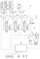
- FIG. 2 is a hydraulic circuit diagram showing the configuration of a hydraulic system of a working machine according to the first embodiment, and a diagram showing a control system of the hydraulic system. Note that in FIG. 2, the broken line indicates a control line.
- the hydraulic excavator is equipped with a hydraulic system 30 that hydraulically drives the lower traveling body 1, the upper rotating body 2, and the front working device 3 (see FIG. 1).
- the hydraulic system 30 includes a hydraulic pump 31 that is driven by a prime mover 32 such as an electric motor or an engine to discharge pressure oil, and a plurality of hydraulic actuators 5, 12, 20, 21 that are driven by the pressure oil discharged from the hydraulic pump 31. , 22.
- a prime mover 32 such as an electric motor or an engine to discharge pressure oil
- a plurality of hydraulic actuators 5, 12, 20, 21 that are driven by the pressure oil discharged from the hydraulic pump 31. , 22.
- the hydraulic actuators include a swing hydraulic motor 5 that swings the upper swing structure 2, and a boom cylinder 20 that moves the boom 17 and arm 18 of the front working device 3. Only the hydraulic circuit related to the arm cylinder 21 is shown. On the other hand, the hydraulic circuits related to the traveling hydraulic motor 12 that causes the lower traveling body 1 to travel and the bucket cylinder 22 that operates the bucket 19 of the front working device 3 are omitted.
- the hydraulic pump 31 is a variable displacement pump, and has a regulator 31a that adjusts the pump volume.
- the regulator 31a adjusts the pump volume according to commands from the control device 80.
- the prime mover 32 has a prime mover controller 32a that controls driving of the prime mover 32.
- the prime mover controller 32a is communicatively connected to the control device 80, and is configured to adjust the rotation speed of the prime mover 32 in accordance with commands from the control device 80.
- the prime mover controller 32a acquires the actual speed of the prime mover 32, which is a detected value of a speed sensor (not shown), and transmits drive information of the prime mover 32 including the acquired speed to the control device 80.
- the boom cylinder 20 and the arm cylinder 21 have first ports 20p1, 21p1 and second ports 20p2, 21p2 as a pair of input/output ports for supplying and discharging pressure oil, and have bottom chambers 20b, 21b and a rod as cylinder chambers. It has chambers 20r and 21r.
- the boom cylinder 20 and the arm cylinder 21 are configured to expand when pressure oil is supplied to the bottom chambers 20b and 21b, and to shorten when pressure oil is supplied to the rod chambers 20r and 21r.
- the swing hydraulic motor 5 has a first port 5a (the left port in FIG. 2) and a second port 5b (the right port in FIG. 2) as a pair of input/output ports for supplying and discharging pressure oil. are doing.
- the swing hydraulic motor 5 is configured, for example, to rotate clockwise when pressure oil is supplied to the first port 5a, and to rotate counterclockwise when pressure oil is supplied to the second port 5b.
- the hydraulic system 30 is configured such that pressure oil from the hydraulic pump 31 is supplied to the boom cylinder 20 via the first meter-in control valve 34 and the first directional control valve 35. There is. Further, pressure oil from the hydraulic pump 31 is supplied to the arm cylinder 21 via a second meter-in control valve 36 and a second directional control valve 37. Further, pressure oil from the hydraulic pump 31 is supplied to the swing hydraulic motor 5 via a third meter-in control valve 38 and a third directional control valve 39.
- the hydraulic pump 31 and each meter-in control valve 34 , 36 , 38 and each directional control valve 35 , 37 , 39 are connected via a discharge line 51 .
- the first directional control valve 35 and the boom cylinder 20 are connected via first actuator lines 53 and 54.
- the first actuator line 53 is connected to the bottom chamber 20b (first port 20p1) of the boom cylinder 20, and the first actuator line 54 is connected to the rod chamber 20r (second port 20p2) of the boom cylinder 20.
- the second directional control valve 37 and the arm cylinder 21 are connected via second actuator lines 55 and 56.
- the second actuator line 55 is connected to the bottom chamber 21b (first port 21p1) of the arm cylinder 21, and the second actuator line 56 is connected to the rod chamber 21r (second port 21p2) of the arm cylinder 21. ing.
- the third directional control valve 35 and the swing hydraulic motor 5 are connected via third actuator lines 57 and 58.
- the third actuator line 57 is connected to the first port 5a of the hydraulic swing motor 5, and the third actuator line 58 is connected to the second port 5b of the hydraulic swing motor 5.
- Each meter-in control valve 34, 36, 38 controls the flow rate of pressure oil (hereinafter sometimes referred to as meter-in flow rate) supplied from the hydraulic pump 31 to the corresponding hydraulic actuator 20, 21, 5.
- Each meter-in control valve 34, 36, 38 has an opening area (hereinafter referred to as a meter-in opening) whose position (stroke amount) is controlled according to a command (for example, a current command value) from the control device 80. ) is configured to change.
- each meter-in control valve 34, 36, 38 has the function of a check valve, and is fully closed when the discharge pressure of the hydraulic pump 31 is lower than the pressure on the side of each hydraulic actuator 20, 21, 5. It is controlled so that
- Each direction control valve 35, 37, 39 switches the flow direction of pressure oil supplied to the corresponding hydraulic actuator 20, 21, 5.
- the directional control valves 35 , 37 , 39 are connected to a hydraulic oil tank 41 via a tank line 52 so as to return the pressure oil discharged from the corresponding hydraulic actuators 20 , 21 , 5 to the hydraulic oil tank 41 . It is configured.
- Each directional control valve 35, 37, 39 has a meter-in passage that is a passage for communicating the discharge line 51 with the meter-in side (pressure oil supply side) of each hydraulic actuator 20, 21, 5, and each hydraulic actuator 20, It has a meter-out passage which is a passage for communicating the meter-out side (pressure oil discharge side) of 21 and 5 with the hydraulic oil tank 41.
- the directional control valves 35, 37, and 39 of this embodiment are meter-out control valves that control the flow rate of pressure oil discharged from the corresponding hydraulic actuators 20, 21, and 5 (hereinafter sometimes referred to as meter-out flow rate). It is configured to function as The opening area of the meter-in passage (hereinafter referred to as meter-in opening) of each directional control valve 35, 37, and 39 is controlled by the position (stroke amount) according to a command from the control device 80 (for example, a current command value).
- the opening area of the meter-out passage (hereinafter sometimes referred to as a meter-out opening) changes as the meter-out passage (hereinafter sometimes referred to as a meter-out opening) changes.
- the directional control valves 35, 37, and 39 are configured, for example, so that the meter-in openings are sufficiently larger than the opening control ranges of the meter-in control valves 34, 36, and 38. That is, the directional control valves 35, 37, and 39 do not have the function of controlling the meter-in flow rate, and only the meter-in control valves 34, 36, and 38 are configured to have the function of controlling the meter-in flow rate.
- a bleed-off valve 42 is provided on a line 59 that branches from the discharge line 51 and is connected to the hydraulic oil tank 41.
- the bleed-off valve 42 releases the pressure oil discharged from the hydraulic pump 31 to the hydraulic oil tank 41 according to its opening, and has a function of adjusting the discharge pressure of the hydraulic pump 31.
- the bleed-off valve 42 is configured so that its opening area changes by controlling its position (stroke amount) in accordance with a command (for example, a current command value) from the control device 80.
- a main relief valve 43 is provided on a relief line 60 that branches from the discharge line 51 and is connected to the hydraulic oil tank 41, which has a function of preventing overload of the hydraulic circuit.
- the main relief valve 43 defines the upper limit of the discharge pressure of the hydraulic pump 31, and is configured to open when the discharge pressure of the hydraulic pump 31 exceeds a set pressure.
- the discharge line 51 is provided with a discharge pressure sensor 61 that detects the discharge pressure of the hydraulic pump 31.
- the discharge pressure sensor 61 outputs a detection signal to the control device 80 according to the detected discharge pressure.
- the first actuator lines 53 and 54 have first actuator pressure sensors 62 and 63 (hereinafter referred to as first pressure sensors) that detect the pressure on the bottom chamber 20b side and the rod chamber 20r side of the boom cylinder 20, respectively.
- the second actuator lines 55 and 56 have second actuator pressure sensors 64 and 65 (hereinafter referred to as second pressure sensors) that detect the pressure on the bottom chamber 21b side and the rod chamber 21r side of the arm cylinder 21, respectively.
- the third actuator lines 57 and 58 are provided with third actuator pressure sensors 66 and 67 (hereinafter referred to as third pressure sensors) that detect the pressure on the first port 5a side and the second port 5b side of the swing hydraulic motor 5, respectively. ) is provided.
- the first to third pressure sensors 62 to 67 output detection signals corresponding to the detected pressures of the hydraulic actuators 20, 21, and 5 to the control device 80.
- the hydraulic excavator is equipped with a joystick 6 as an operating device for operating the hydraulic excavator, and a rotation speed dial 7 that indicates the rotation speed of the prime mover 32.
- the joystick 6 instructs the operation of the front working device 3 (driving the boom cylinder 20, arm cylinder 21, and bucket cylinder 22) and the turning operation of the upper revolving structure 2 (driving the swing hydraulic motor 5).
- the joystick 6 is of an electric type, and outputs an operation signal to the control device 80 according to the operation direction (specification of the pointing target) and the operation angle.
- the rotation speed dial 7 outputs an instruction signal according to the dial position (rotation speed) to the control device 80.
- the control device 80 receives operation signals from the joystick 6, instruction signals from the rotation speed dial 7, detection signals from the discharge pressure sensor 61 (discharge pressure of the hydraulic pump 31), and signals from the first to third pressure sensors 62 to 67. detection signals (pressure of hydraulic actuators 20, 21, 5), detection signals from the first to fifth attitude sensors 24 to 28 (attitude information and operation information of the upper revolving structure 2 and front working device 3), prime mover controller Drive information (including speed information) of the prime mover 32 is taken in from 32a.
- the control device 80 performs predetermined calculations based on these operation signals, instruction signals, detection signals, and drive information, and controls the regulator 31a of the hydraulic pump 31, the meter-in control valves 34, 36, 38, the directional control valves 35, 37, 39, outputs a command according to the calculation result to the bleed-off valve 42 and the prime mover controller 32a.
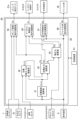
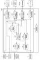
- FIG. 3 is a control block diagram of the control device for the work machine according to the first embodiment shown in FIG. 2.
- the control device 80 includes, as a hardware configuration, a storage device 81 consisting of a RAM, a ROM, etc., and a processing device 82 consisting of a CPU, an MPU, etc.
- the storage device 81 stores information necessary to control the pump volume of the hydraulic pump 31, the drive of each meter-in control valve 34, 36, 38, the drive of each directional control valve 35, 37, 39, and the drive of the bleed-off valve 42. Programs and various information are stored in advance.
- the processing device 82 reads programs and various information from the storage device 81 as appropriate, and implements various functions by executing processes according to the programs.
- the control device 80 controls the speed of the hydraulic actuators 20, 21, 5 according to the operation signal from the operation device 6, and maintains the pressure on the meter-in side of the hydraulic actuators 20, 21, 5 at a predetermined value or higher. It is intended to be controlled.
- the control device 80 of this embodiment performs speed control of the hydraulic actuators 20, 21, 5 by pressure control using pressure target values on the meter-in side and meter-out side of the hydraulic actuators 20, 21, 5.
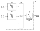
- the control device 80 includes, as control functional units, a target speed calculation unit 91, a target thrust/torque calculation unit 92, a target pressure calculation unit 93, an actual pressure calculation unit 94, a pump volume command calculation unit 95, and a meter-in control unit. It has a valve command calculation section 96, a directional control valve command calculation section 97, and a bleed-off valve command calculation section 98.
- the target speed calculation unit 91 calculates target speeds Vt and ⁇ t of each hydraulic actuator 20, 21, and 5 in accordance with the operation signal from the operation device 6.
- the calculated target speeds Vt and ⁇ t of each hydraulic actuator 20, 21, and 5 are output to the target thrust/torque calculation section 92 and the target pressure calculation section 93. Details of the calculation by the target speed calculation section 91 will be described later.
- the target thrust/torque calculation unit 92 calculates the thrust or torque of the hydraulic actuators 20, 21, 5 necessary to realize the target speeds Vt, ⁇ t of each hydraulic actuator 20, 21, 5 as a result of calculation by the target speed calculation unit 91. is calculated based on the driving states of the hydraulic actuators 20, 21, 22, and 5. Specifically, the operation signal from the operation device 6, the detection signal from each attitude sensor 24 to 28 (attitude information and operation information of the upper revolving body 2 and the front work device 3), and the calculation result of the target speed calculation unit 91. The target thrust Ft of the hydraulic cylinders 20 and 21 and the target torque Tt of the hydraulic motor 5 are calculated using the target speeds Vt and ⁇ t.
- the target thrust/torque calculation section 92 outputs the calculation results of the target thrust Ft and target torque Tt of the hydraulic actuators 20, 21, and 5 to the target pressure calculation section 93. Details of the calculation by the target thrust/torque calculation section 92 will be described later.
- the target pressure calculation section 93 calculates the target speeds Vt, ⁇ t of each hydraulic actuator 20, 21, 5 based on the calculation results of the target speed calculation section 91, and the target speeds Vt, ⁇ t of the hydraulic actuators 20, 21, 5 based on the calculation results of the target thrust/torque calculation section 92. Based on the target thrust Ft and target torque Tt, the meter-in target pressure Pit, which is the target value of the meter-in side pressure of the hydraulic actuators 20, 21, and 5, and the meter-out target pressure Pot, which is the target value of the meter-out side pressure, are determined. In addition to the calculation, the meter-in side of the hydraulic actuators 20, 21, and 5 is determined, and a meter-in flag fg corresponding to the determination result is set.
- the meter-in flag fg as a result of the determination is outputted to the actual pressure calculation unit 94, and the meter-in target pressure Pit of the hydraulic actuators 20, 21, and 5 as a result of the calculation is outputted to the pump volume command calculation unit 95 and the meter-in control valve command calculation unit 96. , outputs the calculated meter-out target pressure Pot of the hydraulic actuators 20, 21, and 5 to the directional control valve command calculating section 97. Details of the calculation by the target pressure calculation section 93 will be described later.
- the actual pressure calculation section 94 uses the detection signals of the first to third pressure sensors 62 to 67 (actual pressures of the hydraulic actuators 20, 21, 5) and the determination results of the target pressure calculation section 93 for the hydraulic actuators 20, 21, 5.
- the meter-in actual pressure Pia which is the actual pressure on the meter-in side of the hydraulic actuators 20, 21, and 5, and the meter-out actual pressure Poa, which is the actual pressure on the meter-out side, of the hydraulic actuators 20, 21, and 5 are calculated based on the meter in flag fg.
- the calculated meter-in actual pressure Pia of the hydraulic actuators 20, 21, 5 is output to the meter-in control valve command calculating section 96, and the calculated meter-out actual pressure Poa of the hydraulic actuators 20, 21, 5 is output to the directional control valve command calculation. output to section 97. Details of the calculation by the actual pressure calculation section 94 will be described later.
- the pump volume command calculation unit 95 calculates the instruction signal from the rotation speed dial 7 (required rotation speed of the prime mover 32), the detection signal from the discharge pressure sensor 61 (actual discharge pressure of the hydraulic pump 31), and the calculation by the target pressure calculation unit 93. Based on the resulting meter-in target pressures Pit of the hydraulic actuators 20, 21, and 5, a volume command value Cq for commanding the pump volume of the hydraulic pump 31 is calculated. The volume command value Cq resulting from the calculation is output to the regulator 31a of the hydraulic pump 31. Details of the calculation by the pump volume command calculation unit 95 will be described later.
- the meter-in control valve command calculation section 96 calculates the operation signal from the operating device 6, the meter-in target pressure Pi of the hydraulic actuators 20, 21, 5 based on the calculation result of the target pressure calculation section 93, and the meter-in actual pressure of the calculation result of the actual pressure calculation section 94.
- a meter-in command value Ci for commanding the driving of the meter-in control valves 34, 36, and 38 is calculated based on the pressure Pia.
- the meter-in command value Ci resulting from the calculation is output to the meter-in control valves 34, 36, and 38. Details of the calculation by the meter-in control valve command calculation section 96 will be described later.
- the directional control valve command calculation unit 97 receives the operation signal from the operating device 6, the meter-out target pressure Pot of the hydraulic actuators 20, 21, 5 based on the calculation result of the target pressure calculation unit 93, and the meter output of the calculation result of the actual pressure calculation unit 94.
- a meter-out command value Cd for commanding the drive of each directional control valve 35, 37, 39 is calculated based on the actual out pressure Poa.
- the meter-out command value Cd resulting from the calculation is output to each direction control valve 35, 37, 39. Details of the calculation by the directional control valve command calculation section 97 will be described later.
- the bleed-off valve command calculation unit 98 calculates a bleed-off command value Cb that commands the drive of the bleed-off valve 42 in response to an operation signal from the operating device 6.
- the bleed-off command value Cb resulting from the calculation is output to the bleed-off valve 42. Details of the calculation by the bleed-off valve command calculation section 98 will be described later.
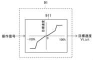
- FIG. 4 is a control block diagram of the target speed calculating section in the control device according to the first embodiment shown in FIG. 3.
- the target speed calculating unit 91 calculates the target speeds Vt and ⁇ t of each hydraulic actuator based on the operation signal from the operating device 6 by referring to the table 911 shown in FIG.
- the operation signal of the operation device 6 is 0% when not operated, and changes from -100% to +100% depending on the operation direction and amount of operation.
- the hydraulic actuator is a hydraulic cylinder
- the speed in the extension direction of the hydraulic cylinder is set as positive
- the speed in the shortening direction is set as negative.
- the hydraulic actuator is a hydraulic motor
- the speed of right rotation of the hydraulic motor is positive
- the speed of left rotation of the hydraulic motor is negative.
- FIG. 5 is a control block diagram of the target thrust/torque calculation section in the control device according to the first embodiment shown in FIG. 3.
- the target thrust/torque calculation section 92 calculates the operating state of the front working device 3 (driven body) that can achieve the target speed Vt of the hydraulic cylinders 20, 21, 22, which is the calculation result of the target speed calculating section 91, as a front working device. This calculation takes into consideration the inertia (self-weight) of 3. Specifically, as shown in FIG. 5, the target thrust/torque calculation section 92 includes a conversion section 921A, a rate restriction section 922, a target angular acceleration calculation section 923, a required torque calculation section 924, a deviation calculation section 925, and a feedback calculation section. 926, a torque limiter 927, an absolute torque limiter 928, an adder 929, and a converter 921B.
- the conversion unit 921A converts the target speed Vt of the hydraulic cylinders 20, 21, 22, which is the calculation result of the target speed calculation unit 91, into the angular velocity of each component 17, 18, 19 of the front working device 3 or their joint parts 18a, 19a. It is converted into .
- the converter 921A is, for example, a Jacobian inverse matrix that converts the cylinder coordinate system of the hydraulic cylinders 20, 21, 22 to the angular coordinate system of the joint parts 18a, 19a.
- the converter 921A outputs the angular velocity of the calculation result to the rate limiter 922.
- the rate limiting unit 922 determines the rate of change (rate) of increase and decrease per unit time with respect to the angular velocity of the joint parts 18a, 19a (boom 17, arm 18, bucket 19) of the front working device 3 as a result of the calculation by the converting unit 921A. ).
- the rate limiting unit 922 outputs a target angular velocity obtained by limiting the rate of the angular velocity calculated by the converting unit 921A to the target angular acceleration calculating unit 923 and the deviation calculating unit 925.
- the rate limit can be set to a predetermined value or changed according to conditions.
- the target angular acceleration calculation unit 923 calculates the target angular acceleration of the joint parts 18a, 19a (boom 17, arm 18, bucket 19) of the front working device 3 by time-differentiating the target angular velocity output from the rate limiting unit 922. calculate.
- the target angular acceleration resulting from the calculation is output to the required torque calculation section 924.
- the required torque calculation unit 924 calculates the joint parts 18a and 19a (boom 17, arm 18, bucket 19 ), the joint parts 18a, 19a (boom 17, arm 18, bucket 19) of the front working device 3 are calculated based on the calculation results of the target angular acceleration calculation unit 923.
- the required torque ⁇ which is the torque required to achieve a driving state in which a certain target angular acceleration can be achieved, is calculated.
- the required torque calculation unit 924 calculates the required torque ⁇ using the following equation of motion for rotational motion.
- ⁇ is the actual angle of the joint parts 18a and 19a of the boom 17, arm 18, and bucket 19 of the front working device 3, and ⁇ with a dot symbol on the upper side is the joint part 18a and 19a of the boom 17, arm 18, and bucket 19.
- the actual angular velocity ⁇ t with a double dot symbol above indicates the target angular acceleration of the joint portions 18a and 19a of the boom 17, arm 18, and bucket 19.
- the posture information and motion information of the posture sensors 25 to 28 are substituted for ⁇ and ⁇ with a dot symbol, and the target of the calculation result of the target angular acceleration calculation unit 923 is substituted for ⁇ t with a double dot symbol. Substitute the angular acceleration. Thereby, the required torque ⁇ is calculated. The required torque ⁇ resulting from the calculation is output to the adding section 929.
- the deviation calculation unit 925 calculates the target angular velocity output from the rate limiting unit 922 and the actual angular velocity of the joint parts 18a and 19a (boom 17, arm 18, bucket 19) of the front working device 3, which is the detected value of the attitude sensors 25 to 28. It calculates the deviation from the The angular velocity deviation resulting from the calculation is output to the feedback calculation section 926.
- the feedback calculation unit 926 calculates a feedback correction value for the target torque by feedback control such as PI control or PID control based on the angular velocity deviation that is the calculation result of the deviation calculation unit 925.
- the feedback correction value of the calculation result is output to the torque absolute value limiting section 928.
- the torque limiting section 927 uses a table stored in advance in the storage device 81 to control the joint portions 18a and 19a of the respective structural members 17, 18, and 19 of the front working device 3 in accordance with the operation signal from the operating device 6. It outputs the torque limit value.
- the torque limit value is output to the torque absolute value limiter 928.
- the torque absolute value limiter 928 limits the absolute value of the feedback correction value of the calculation result of the feedback calculator 926 using the torque limit value from the torque limiter 927.
- the feedback correction value whose absolute value is limited by the torque limit value is output to the adding section 929.
- the adding unit 929 adds the feedback correction value output from the torque absolute value limiting unit 928 to the required torque ⁇ calculated by the required torque calculating unit 924, thereby adjusting the joint parts 18a, 19a ( The target torques of the boom 17, arm 18, and bucket 19) are calculated.
- the target torque resulting from the calculation is output to the converter 921B.
- the conversion unit 921B converts the target torque of the joint parts 18a, 19a (boom 17, arm 18, bucket 19) of the front working device 3 from the addition unit 929 into the target thrust force Ft of the hydraulic cylinders 20, 21, 22.
- the converter 921B is an inverse calculation of the converter 921A, and is, for example, a Jacobian matrix that converts the angular coordinate system of the joint parts 18a, 19a to the cylinder coordinate system of the hydraulic cylinders 20, 21, 22.
- the target speed that is the calculation result of the target speed calculation unit 91 is not the hydraulic cylinders 20, 21, and 22 that operate the front working device 3 but the swing hydraulic motor 5 that swings the upper swing structure 2, the above-mentioned The functional units 921A, 921B to 929 are changed as follows.
- the conversion unit 921A converts the target speed ⁇ t of the swing hydraulic motor 5, which is the calculation result of the target speed calculation unit 91, into the swing speed (angular velocity) of the upper rotating structure 2.
- the conversion unit 921A is, for example, a reduction ratio of the rotation of the upper rotating body 2 to the rotation of the swing hydraulic motor 5.
- the conversion unit 921B is an inverse calculation of the conversion unit 921A, and converts the swing target torque of the upper revolving structure 2 into the target torque of the swing hydraulic motor 5.
- the required torque calculation unit 924 uses the equation of motion of the rotational motion of the upper rotating body 2 in place of the equation of motion of the rotational motion of the joint portions 18a and 19a of the front working device 3. That is, the required torque calculation unit 924 calculates the calculation result of the target angular acceleration calculation unit 923 based on the actual turning angle (actual angle) and the actual turning speed (actual angular velocity) of the upper rotating structure 2, which are the detected values of the attitude sensor 24.
- the required torque ⁇ required for the upper revolving superstructure 2 to be in a driving state in which it can achieve the target angular acceleration is calculated.
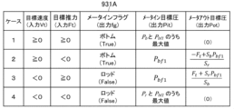
- FIG. 6 is a table showing an example of a calculation method (in the case of a hydraulic cylinder) of the target pressure calculation section in the control device according to the first embodiment shown in FIG.
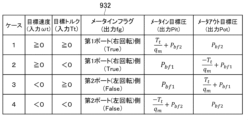
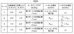
- FIG. 7 is a table showing another example (in the case of a hydraulic motor) of the calculation method of the target pressure calculation section in the control device according to the first embodiment shown in FIG.
- the target pressure calculation section 93 calculates the target speed Vt of the hydraulic actuators 5, 20, 21, 22 from the target speed calculation section 91, the positive/negative of ⁇ t, and the target thrust/torque calculation section 92 of the hydraulic actuators 5, 20, 21, 22.
- the situations of the hydraulic actuators 5, 20, 21, and 22 are classified based on the sign of the target thrust Ft and the target torque Tt. Furthermore, depending on the case, the pressure oil supply side of the hydraulic actuators 5, 20, 21, 22 is determined and the meter flag fg is set, and the pressure oil supply side of the hydraulic actuators 5, 20, 21, 22 is determined.
- a meter-in target pressure, which is a target pressure, and a meter-out target pressure, which is a target pressure on the pressure oil discharge side, are calculated.
- a table 931 is used when the hydraulic actuator is the hydraulic cylinders 20, 21, and 22, and a table 932 is used when the hydraulic actuator is the hydraulic motor 5.
- Case 1 is defined as a case where the target thrust force Ft or target torque Tt of the hydraulic actuators 20, 21, and 5 is positive (more precisely, 0 or more).
- Case 2 is a case in which the target speeds Vt and ⁇ t are positive and the target thrust Ft or target torque Tt is negative.
- Case 3 is a case where the target speeds Vt and ⁇ t are negative and the target thrust Ft or target torque Tt is positive (more precisely, 0 or more).
- Case 4 is a case in which the target speeds Vt and ⁇ t are negative, and the target thrust Ft or target torque Tt is negative.
- the hydraulic actuators are hydraulic cylinders 20 and 21, the thrust in the extension direction of the hydraulic cylinders 20 and 21 is positive, and the thrust in the contraction direction is negative.
- the hydraulic actuator is the hydraulic motor 5
- the torque in the clockwise rotation direction of the hydraulic motor 5 is positive, and the torque in the counterclockwise rotation direction is negative.
- a table 931 shown in FIG. 6 is used.
- the meter flag is set to the bottom chambers 20b and 21b of the hydraulic cylinders 20 and 21.
- the cylinder chamber on the meter-out side has a lower pressure than the cylinder chamber on the meter-in side. Therefore, the meter-out target pressure Pot is set to a minimum pressure Pbf2 that does not cause cavitation in the cylinder chamber on the meter-out side.
- the lowest pressure Pbf2 is, for example, about 1 MPa.
- the meter-in target pressure Pit is obtained by dividing the sum of the meter-out side thrust (the thrust generated by the set pressure Pbf2) and the target thrust Ft by the cross-sectional area of the meter-in side cylinder chamber.
- the cylinder chambers on the meter-in side are bottom chambers 20b and 21b
- the cylinder chambers on the meter-out side are rod chambers 20r and 21r.
- the meter-in target pressure Pit is calculated from the following equation.
- Sb represents the cross-sectional area of the hydraulic cylinders 20 and 21 on the bottom chambers 20b and 21b side
- Sr represents the cross-sectional area of the rod chambers 20r and 21r side
- Ft represents the target thrust of the hydraulic cylinders 20 and 21.
- the meter flag is set to the bottom chambers 20b and 21b side.
- the cylinder chambers on the meter-in side of the hydraulic cylinders 20 and 21 have a lower pressure than the cylinder chambers on the meter-out side. Therefore, the meter-in target pressure Pit is set to a predetermined pressure Pbf1 that does not cause cavitation in the cylinder chamber on the meter-in side.
- the predetermined pressure Pbf1 is a pressure higher than the lowest pressure Pbf2 set in case 1, and is, for example, about 3 MPa.
- the meter-out target pressure Pot is obtained by subtracting the target thrust Ft from the meter-in thrust (the thrust generated by the predetermined pressure Pbf1) and dividing the value by the cross-sectional area of the meter-out cylinder chamber.
- the cylinder chambers on the meter-in side are bottom chambers 20b, 21b, and the cylinder chambers on the meter-out side are rod chambers 20r, 21r. Therefore, the meter-out target pressure Pot is calculated from the following equation.
- the meter flag is set on the rod chambers 20r, 21r side of the hydraulic cylinders 20, 21.
- the cylinder chamber on the meter-in side has a lower pressure than the cylinder chamber on the meter-out side. Therefore, similarly to Case 2, the meter-in target pressure Pit is set to a predetermined pressure Pbf1 that does not cause cavitation in the cylinder chamber on the meter-in side.
- the meter-out target pressure Pot is obtained by dividing the sum of the meter-in side thrust (the thrust generated by the predetermined pressure Pbf1) and the target thrust Ft by the cross-sectional area of the meter-out side cylinder chamber.
- the meter-out target pressure Pot is calculated from the following equation.
- the meter flag is set to the rod chambers 20r and 21r side.
- the cylinder chamber on the meter-out side has a lower pressure than the cylinder chamber on the meter-in side. Therefore, similarly to Case 1, the meter-out target pressure Pot is set to the lowest pressure Pbf2.
- the meter-in target pressure Pit is obtained by dividing the value obtained by subtracting the target thrust Ft from the meter-out side thrust (the thrust generated by the lowest pressure Pbf2) by the cross-sectional area of the meter-in side cylinder chamber.
- the meter-in target pressure Pit is calculated from the following equation.
- the target pressure calculation unit 93 outputs "True” when the meter infrastructure flag is the bottom chambers 20b and 21b, and outputs "False” when the meter infrastructure flag is the rod chambers 20r and 21r. is configured to do so. Also, the initial value of the meter flag is set to "True”. Note that it is also possible to reverse the relationship between "True” and “False” of the meter flag.
- the hydraulic actuator is the hydraulic motor 5
- a table 932 shown in FIG. 7 is used.
- the meter flag is set to the first port 5a (clockwise rotation) side.
- the meter-out side port of the hydraulic motor 5 has a lower pressure than the meter-in side port. Therefore, similarly to the case of the hydraulic cylinders 20 and 21, the meter-out target pressure Pot is set to the lowest pressure Pbf2 at which cavitation does not occur on the meter-out side of the hydraulic motor 5.
- the meter-in target pressure Pit is obtained by the sum of the calculation result obtained by dividing the target torque Tt by the pump volume qm stored in advance in the storage device 81 and the pressure on the meter-out side of the hydraulic motor 5, that is, the set minimum pressure Pbf2. . That is, the meter-in target pressure Pit is calculated from the following equation.
- case 2 similarly to case 1, set the meter flag to the first port 5a (clockwise rotation) side.
- the meter-in side port has a lower pressure than the meter-out side port. Therefore, the meter-in target pressure Pit is set to a predetermined pressure Pbf1 that does not cause cavitation on the port side of the meter-in. Since the meter-in side port of the hydraulic motor 5 has a high risk of cavitation occurring on the suction side, the predetermined pressure Pbf1 is set to a pressure higher than the minimum pressure Pbf2 set in case 1, as in the case of the hydraulic cylinders 20 and 21. do.
- the meter-out target pressure Pot is obtained by subtracting the calculation result obtained by dividing the target torque Tt by the pump volume qm from the pressure on the meter-in side of the hydraulic motor 5, that is, the set predetermined pressure Pbf1. That is, the meter-out target pressure Pot is calculated from the following equation.
- the meter-in target pressure Pit is set to a predetermined pressure Pbf1 that does not cause cavitation on the meter-in port side.
- the meter-out target pressure Pot is obtained by the sum of the calculation result obtained by dividing the target torque Tt by the pump volume qm and the pressure on the meter-in side of the hydraulic motor 5, that is, the set predetermined pressure Pbf1. That is, the meter-out target pressure Pot is calculated from the following equation.
- the meter flag is set to the second port 5b (left rotation) side.
- the meter-out side port has a lower pressure than the meter-in side port. Therefore, similarly to Case 1, the meter-out target pressure Pot is set to the lowest pressure Pbf2.
- the meter-in target pressure Pit is obtained by subtracting the calculation result obtained by dividing the target torque Tt by the pump volume qm from the pressure on the meter-out side of the hydraulic motor 5, that is, the set minimum pressure Pbf2. That is, the meter-in target pressure Pit is calculated from the following equation.
- FIG. 8 is a control block diagram of the actual pressure calculating section in the control device according to the first embodiment shown in FIG.
- the actual pressure calculation unit 94 has functional units of a meter-in selection unit 941, a NOT calculation unit 942, and a meter-out selection unit 943, as shown in FIG. 8, for example.
- the meter-in selection unit 941 selects the detection signals of the first to second pressure sensors 62 to 65 (the bottom chambers 20b and 21b of the hydraulic cylinders 20 and 21 and the rod chamber 20r, The actual pressure on the meter-in side of the hydraulic cylinders 20 and 21 is output based on the meter flag fg as a result of processing by the target pressure calculating section 93. That is, when the meter flag fg is "True", the actual pressure in the bottom chambers 20b, 21b of the hydraulic cylinders 20, 21 is output as the actual pressure on the meter-in side. On the other hand, when the meter flag fg is "False", the actual pressure in the rod chambers 20r, 21r of the hydraulic cylinders 20, 21 is output as the actual pressure on the meter-in side.
- the detection signals of the third pressure sensors 66 and 67 (the actual pressures on the first port 5a side and the second port 5b side of the swing hydraulic motor 5) and the target pressure calculation section 93 are used.
- the actual pressure on the meter-in side of the hydraulic motor 5 is output based on the meter in flag fg as a result of the processing. That is, when the meter in flag fg is "True”, the actual pressure on the first port 5a side of the swing hydraulic motor 5 is output as the actual pressure on the meter-in side.
- the meter infrastructure fgg is "False"
- the actual pressure on the second port 5b side of the swing hydraulic motor 5 is output as the actual pressure on the meter-in side.
- the NOT calculation unit 942 inverts the meter in flag fg as a result of processing by the target pressure calculation unit 93 and inputs it to the meter out selection unit 943. That is, when the meter in flag fg is "True”, “False” is input to the meter out selection section 943. On the other hand, when the meter in flag fg is "False”, “True” is input to the meter out selection section 943.
- the meter-out selection unit 943 selects the detection signals of the first to second pressure sensors 62 to 65 (the bottom chambers 20b and 21b of the hydraulic cylinders 20 and 21 and the rod chamber 20r). , 21r) and the processing result of the NOT calculation unit 942 (inversion of the meter in flag fg), the actual pressure on the meter-out side of the hydraulic cylinders 20 and 21 is output. Since the meter-out selection section 943 receives the result of the inversion processing of the meter-in flag fg by the NOT calculation section 942, it outputs the actual pressure in the cylinder chamber that is different from the meter-in selection section 941, that is, the actual pressure on the meter-out side.
- the hydraulic actuator is the hydraulic motor 5
- the detection signals of the third pressure sensors 66 and 67 (the actual pressures on the first port 5a side and the second port 5b side of the swing hydraulic motor 5) and the NOT calculation unit 942 Based on the processing results, the actual pressure on the meter-out side of the hydraulic motor 5 is output.
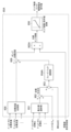
- FIG. 9 is a control block diagram of the pump volume command calculation section in the control device according to the first embodiment shown in FIG. 3.
- the pump volume command calculation unit 95 includes the following functional units: a maximum value selection unit 951, an addition unit 952, a deviation calculation unit 953, a feedback calculation unit 954, a target pump volume calculation unit 955, and a command conversion unit 956. There is.
- the maximum value selection section 951 selects the maximum value of the meter-in target pressures of all the hydraulic actuators 20, 21, and 5 output from the target pressure calculation section 93, and adds the maximum value of the selected meter-in target pressures to the addition section 952. Output to.
- the addition unit 952 calculates the target discharge pressure of the hydraulic pump 31 by adding the buffer pressure Pbf3 to the maximum value of the meter-in target pressures of the hydraulic actuators 20, 21, and 5 output from the maximum value selection unit 951. .
- the buffer pressure Pbf3 is stored in advance in the storage device 81 and is, for example, 1 MPa.
- the buffer pressure Pbf3 takes into consideration the pressure loss that occurs between the hydraulic pump 31 and the hydraulic actuators 20, 21, and 5. This is intended to improve the controllability of the meter-in flow rate control of the hydraulic actuators 20, 21, and 5 by increasing the target discharge pressure of the hydraulic pump 31 by the pressure loss.
- the calculated target discharge pressure of the hydraulic pump 31 is output to the deviation calculating section 953.
- the deviation calculation unit 953 calculates the deviation between the target discharge pressure of the hydraulic pump 31 from the addition unit 952 and the actual discharge pressure of the hydraulic pump 31, which is the detected value of the discharge pressure sensor 61.
- the deviation of the calculation result is output to the feedback calculation section 954.
- the feedback calculation unit 954 calculates the target flow rate of the hydraulic pump 31 as a control amount by feedback control such as PI control or PID control based on the discharge pressure deviation of the hydraulic pump 31 which is the calculation result of the deviation calculation unit 953.
- the target flow rate of the hydraulic pump 31 as a feedback control amount of the calculation result is output to the target pump volume calculation section 955.
- the target pump volume calculation section 955 calculates the hydraulic pressure by dividing the pump target flow rate, which is the calculation result of the feedback calculation section 954, by the required rotation speed of the prime mover 32 (for example, converted based on the instruction signal from the rotation speed dial 7). A target pump volume of the pump 31 is calculated. The target pump volume of the hydraulic pump 31 resulting from the calculation is output to the command conversion unit 956.
- the command conversion unit 956 converts the target pump volume of the hydraulic pump 31, which is the calculation result of the target pump volume calculation unit 955, into a command value (for example, a drive current command value to a pump control solenoid (not shown)).
- the command conversion unit 956 outputs a command value to the regulator 31a of the hydraulic pump 31.
- FIG. 10 is a control block diagram of a meter-in control valve command calculation section in the control device according to the first embodiment shown in FIG.
- the meter-in control valve command calculation unit 96 has the following functional units: a meter-in opening conversion unit 961, a deviation calculation unit 962, a feedback calculation unit 963, a meter-in target opening calculation unit 964, and a command conversion unit 965.
- the meter-in opening converter 961 calculates the required opening values of the meter-in control valves 34, 36, and 38 based on the operation signal from the operating device 6.
- the calculated required opening values of the meter-in control valves 34, 36, and 38 are output to the meter-in target opening calculating section 964.
- the deviation calculation section 962 calculates the meter-in target pressures of the hydraulic actuators 20, 21, and 5, which are the calculation results of the target pressure calculation section 93, and the meter-in side actual pressures of the hydraulic actuators 20, 21, and 5, which are the calculation results of the actual pressure calculation section 94. Calculate the deviation from the pressure. The pressure deviation resulting from the calculation is output to the feedback calculation section 963.
- the feedback calculation unit 963 controls the meter-in control valves 34, 36, 38 by feedback control such as PI control or PID control based on the pressure deviation on the meter-in side of the hydraulic actuators 20, 21, 5, which is the calculation result of the deviation calculation unit 962. This is to calculate a feedback correction value for the target aperture.
- the feedback correction value of the calculation result is output to the meter-in target aperture calculation section 964.
- the meter-in target opening calculation unit 964 adds the feedback correction value, which is the calculation result of the feedback calculation unit 963, to the opening request value, which is the calculation result of the meter-in opening conversion unit 961, to adjust the meter-in control valves 34, 36, and 38. Calculate the target aperture.
- the calculated target openings of the meter-in control valves 34, 36, and 38 are output to the command conversion section 965.
- the command conversion unit 965 converts target openings of the meter-in control valves 34, 36, and 38, which are the calculation results of the meter-in target opening calculation unit 964, into command values (for example, current command values) for driving the meter-in control valves 34, 36, and 38. ).
- the command converter 965 outputs a current command value to the solenoids of the meter-in control valves 34, 36, and 38.
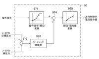
- FIG. 11 is a control block diagram of the directional control valve command calculating section in the control device according to the first embodiment shown in FIG.
- the directional control valve command calculation unit 97 calculates the meter-out target of the hydraulic actuators 20, 21, 5 obtained from the operation signal from the operation device 6 and the target speed Vt ( ⁇ t) according to the operation signal of the operation device 6.
- a meter-out command value Cd for controlling the directional control valves 35, 37, and 39 is calculated based on the pressure Pot.
- the directional control valve command calculation unit 97 has the following functional units: a meter-out opening conversion unit 971, a deviation calculation unit 972, a feedback calculation unit 973, a meter-out target opening calculation unit 974, and a command conversion unit 975.
- the meter-out opening conversion unit 971 calculates the required meter-out opening values of the directional control valves 35, 37, and 39 based on the operation signal of the operating device 6.
- the calculated meter-out opening request values for the directional control valves 35, 37, and 39 are output to the meter-out target opening calculating section 974.
- the deviation calculation section 972 calculates the meter-out target pressures of the hydraulic actuators 20, 21, and 5, which are the calculation results of the target pressure calculation section 93, and the meter-out side of the hydraulic actuators 20, 21, and 5, which are the calculation results of the actual pressure calculation section 94. Calculate the deviation from the actual pressure. The pressure deviation resulting from the calculation is output to the feedback calculation section 973.
- the feedback calculation unit 973 controls the direction control valves 35, 37, 39 by feedback control such as PI control or PID control based on the pressure deviation on the meter-out side of the hydraulic actuators 20, 21, 5, which is the calculation result of the deviation calculation unit 972.
- the feedback correction value of the meter-out target aperture is calculated.
- the feedback correction value of the calculation result is output to the meter-out target aperture calculation section 974.
- the meter-out target opening calculation unit 974 adds the feedback correction value, which is the calculation result of the feedback calculation unit 973, to the meter-out opening request value, which is the calculation result of the meter-out opening conversion unit 971. 37 and 39, the meter-out target apertures are calculated. The meter-out target openings of the directional control valves 35, 37, and 39 as a result of the calculation are output to the command conversion section 975.
- the command conversion unit 975 converts the meter-out target openings of the directional control valves 35, 37, 39, which are the calculation results of the meter-out target opening calculation unit 974, into command values for driving the directional control valves 35, 37, 39 (for example, current command value).
- the command conversion unit 975 outputs a current command value to the solenoids of the directional control valves 35, 37, and 39.
- FIG. 12 is a control block diagram of the bleed-off valve command calculation section in the control device according to the first embodiment shown in FIG.
- the bleed-off valve command calculation unit 98 has the functional units of a bleed-off opening conversion unit 981, a minimum value selection unit 982, and a command conversion unit 983.
- the bleed-off opening conversion unit 981 calculates the required opening value of the bleed-off valve 42 based on the operation signal of each operation (boom operation, arm operation, swing operation, etc.) from the operating device 6.
- the required opening value of the bleed-off valve 42 for each operation based on the calculation result is outputted to the minimum value selection section 982, respectively.
- the minimum value selection unit 982 selects the minimum value from among all the required opening values of the bleed-off valves 42 as the calculation results of the bleed-off opening conversion unit 981.
- the minimum value of the selected opening request for the bleed-off valve 42 is output to the command conversion unit 983 as the target opening of the bleed-off valve 42.
- the command conversion unit 983 converts the target opening of the bleed-off valve 42 output from the minimum value selection unit 982 into a command value (for example, a current command value) for driving the bleed-off valve 42.
- the command conversion unit 983 outputs a current command value to the solenoid of the bleed-off valve 42.
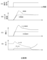
- FIG. 13 is a diagram showing changes in the operating states of the hydraulic cylinder, meter-in control valve, and directional control valve with respect to arm crowd operation in a known work machine as a comparative example with respect to the work machine according to the first embodiment.
- Graphs (A) to (D) shown in FIG. 13 show graphs when a single operation of the arm cloud is input to the operating device 6 while the front working device 3 is maintained in the air.
- Graph (A) shows the change over time of the operation signal for single operation of the arm cloud.
- Graph (B) shows changes in the target speed and actual speed of the hydraulic cylinder (arm cylinder 21) with respect to the operation signal of the operation device 6.
- Graph (C) shows changes in the openings of the meter-in control valve and the direction control valve in response to the operation signal of the operation device 6.
- Graph (D) shows changes in the pressure in the bottom chamber (bottom pressure) and the pressure in the rod chamber (rod pressure) of the arm cylinder with respect to the operation signal of the operation device 6.
- the opening of the meter-in control valve that controls the meter-in flow rate of the arm cylinder is made larger than under normal control.
- the bottom pressure of the arm cylinder is maintained higher than the pressure at which cavitation occurs.
- the driving speed of the arm cylinder becomes faster than the target speed according to the operation of the operating device, as shown by the broken line in graph (B).
- the driving speed of the arm cylinder becomes faster than the target speed according to the operation of the operating device, as shown by the broken line in graph (B).
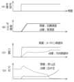
- FIG. 14 is a diagram showing changes in the operating states of the hydraulic cylinder, meter-in control valve, and directional control valve in response to arm cloud operation in the work machine according to the first embodiment.
- Graphs (A) to (D) shown in FIG. 14 are similar to the graph shown in FIG. 13 when a single operation of the arm cloud is input to the operating device 6 while the front working device 3 is maintained in the air. It shows the waveforms of changes in the driving states of the hydraulic cylinder, meter-in control valve, and directional control valve in the case of
- the control device 80 calculates a target speed Vt of the arm cylinder 21 according to the operation signal, and sets a target speed Vt that satisfies the target speed Vt as a result of the calculation. Calculate thrust force Ft. Further, a meter-in target pressure Pit and a meter-out target pressure Pot of the arm cylinder 21 are calculated according to the sign of the target speed Vt and the target thrust Ft of the calculation results.
- a state corresponding to case 2 of table 931 shown in FIG. 6 is passed.
- the pressure target value (meter-in target pressure Pit) of the bottom chamber 21b of the arm cylinder 21 is set to a predetermined value Pbf1 that can prevent the occurrence of cavitation, while the target pressure value (meter-out target pressure Pot) of the rod chamber 21r is set. is set according to the target thrust Ft that can achieve the target speed Vt and the predetermined value Pbf1 on the meter-in side.
- the control device 80 determines the pump volume of the hydraulic pump 31, the opening of the meter-in control valve 36, and the meter-out opening of the direction control valve 37 based on the calculated meter-in target pressure Pit and meter-out target pressure Pot of the arm cylinder 21. Control. Specifically, while controlling the meter-out opening of the direction control valve 37 so that the arm cylinder 21 reaches the target speed Vt according to the operation of the operating device 6, the pressure ( The opening of the meter-in control valve 36 and the pump volume of the hydraulic pump 31 are controlled so that the bottom pressure) becomes equal to or higher than the pressure value Pbf1 (meter-in target pressure Pit) at which cavitation can be prevented.
- Pbf1 meter-in target pressure Pit
- the hydraulic excavator (work machine) includes hydraulic actuators 20, 21, which operate driven bodies 17, 18, 19, 2 by being driven by supplying and discharging pressure oil (working fluid). 22, 5 (hydraulic actuator), a hydraulic pump 31 (pump) that supplies pressure oil (working fluid) to the hydraulic actuators 20, 21, 22, 5 (hydraulic actuator), and hydraulic pump 31 (pump).
- Meter-in control valves 34, 36, 38 that can control the flow rate of pressure oil (working fluid) supplied from the hydraulic actuators 20, 21, 22, 5 (fluid pressure actuators) to the hydraulic actuators 20, 21, 22, 5
- Directional control valves 35, 37, 39 as meter-out control valves that can control the flow rate of pressure oil (working fluid) discharged from (fluid pressure actuator), hydraulic actuators 20, 21, 22, 5 (fluid pressure actuator) ), and control for controlling the hydraulic pump 31 (pump), meter-in control valves 34, 36, 38, and directional control valves 35, 37, 39 (meter-out control valves).
- a device 80 is provided.
- the control device 80 calculates target speeds Vt, ⁇ t of the hydraulic actuators 20, 21, 22, 5 (fluid pressure actuators) according to the operation signal from the operating device 6,
- the target thrust Ft or target torque Tt of the hydraulic actuators 20, 21, 22, 5 (fluid pressure actuators) is calculated based on the driving state of the hydraulic actuators), and the target speed Vt of the calculation result, the sign of ⁇ t is the target of the calculation result. If the positive or negative of the thrust force Ft or the target torque Tt is different, the speed of the hydraulic actuators 20, 21, 22, 5 (fluid pressure actuators) is adjusted based on the operation signal from the operating device 6.
- the hydraulic pump 31 (pump) or the meter-in control valves 34, 36 are controlled by the meter-out control valve (meter-out control valve), and the pressure on the meter-in side of the hydraulic actuators 20, 21, 22, 5 (fluid pressure actuators) is equal to or higher than a predetermined value. , 38.
- the driving speed of the hydraulic actuators 20, 21, 22, 5 is controlled by the operating device 6.
- the pressure on the meter-in side of the hydraulic actuators 20, 21, 22, 5 is controlled to exceed a predetermined value while being controlled by the directional control valves 35, 37, 39 (meter-out control valves) according to the operation. Since at least one of the hydraulic pump 31 (pump) or the meter-in control valves 34, 36, and 38 is controlled, by setting the predetermined value to a value that can avoid occurrence of cavitation, the hydraulic pressure can be adjusted according to the operation of the operating device 6. Cavitation of the hydraulic actuators 20, 21, 22, 5 (hydraulic actuators) can be prevented while realizing speed control of the actuators 20, 21, 22, 5 (hydraulic actuators).
- the hydraulic excavator (work machine) also includes a discharge pressure sensor 61 (first pressure sensor) that detects the discharge pressure of the hydraulic pump 31 (pump), and hydraulic actuators 20, 21, 22, 5 ( actuator pressure sensors 62 to 67 (second pressure sensors) that detect pressure on the meter-in side of the fluid pressure actuator).
- the control device 80 is configured to calculate the target thrust Ft or the target torque Tt based on the calculated target speeds Vt and ⁇ t.
- the control device 80 controls the pressure on the meter-in side of the hydraulic actuators 20, 21, 22, and 5 (fluid pressure actuators) when the sign of the target speed Vt as a calculation result is different from the sign of the target thrust Ft or target torque Tt as the calculation result.
- the target value, meter-in target pressure Pit is set to a predetermined value or higher, and the hydraulic actuators 20, 21, 22, 5 (fluid pressure actuators) are operated based on the calculated target thrust Ft or target torque Tt and the set meter-in target pressure Pit.
- Calculate the meter-out target pressure Pot which is the target value of the pressure on the meter-out side of
- the hydraulic pump 31 (pump) is controlled based on the set meter-in target pressure Pit and the detected value of the discharge pressure sensor 61 (first pressure sensor), and the hydraulic pump 31 (pump) is controlled based on the set meter-in target pressure Pit and the detected value of the actuator pressure sensors 62 to 67 (second pressure sensor).
- the meter-in control valves 34, 36, and 38 are controlled based on the detected value of the sensor.
- the hydraulic actuators 20, 21, 22, 5 are controlled by pressure control using the pressure target values Pit and Pot on the meter-in side and the meter-out side of the hydraulic actuators 20, 21, 22, 5 (fluid pressure actuators). (Fluid pressure actuator) speed control can be performed.
- the hydraulic excavator (work machine) also includes first to fifth attitude sensors 24 to 28 (attitude detection devices) that detect attitude information of the driven bodies 17, 18, 19, and 2. .
- the control device 80 also detects the detection information of the first to fifth attitude sensors 24 to 28 (attitude detection devices) as the driving states of the hydraulic actuators 20, 21, 22, and 5 (fluid pressure actuators) and the driven body 17. , 18, 19, and 2 to calculate the target thrust Ft or target torque Tt.
- FIG. 15 is a hydraulic circuit diagram showing the configuration of a hydraulic system for a working machine according to a second embodiment of the present invention, and a diagram showing a control system for the hydraulic system.
- FIG. 16 is a control block diagram of the control device for the work machine according to the second embodiment shown in FIG. 15.
- the second embodiment shown in FIGS. 15 and 16 differs from the first embodiment in that the second attitude sensor 25 (see FIGS. 1 and 2) that detects the attitude information of the upper rotating body 2 is not required.
- the third to fifth posture sensors 26 to 28 (see FIGS. 1 and 2) that detect posture information and operation information of the front working device 3 are not required, and the hydraulic actuators 20 and 21 are controlled by the control device 80A. , 5 differs depending on the deletion of the second to fifth attitude sensors 25 to 28.
- the control device 80A of this embodiment controls the speed of the hydraulic actuators 20, 21, and 5 according to the operation signal from the operation device 6, and , 21, 5 on the meter-in side is controlled to be maintained at a predetermined value or higher.
- the control device 80A of this embodiment controls the speed of the hydraulic actuators 20, 21, 5 by controlling the flow rate using the flow rate target value on the meter-out side of the hydraulic actuators 20, 21, 5. It is for controlling.
- the control device 80A shown in FIG. 16 includes a target speed calculation section 91, a target thrust/torque calculation section 92A, a target pressure calculation section 93A, an actual pressure calculation section 94A, a pump volume command calculation section 95A, and a meter-in control valve.
- a target flow rate calculation unit 101 is provided in addition to the functional units of a command calculation unit 96A, a directional control valve command calculation unit 97A, and a bleed-off valve command calculation unit 98.
- the target speed calculation unit 91 and the bleed-off valve command calculation unit 98 are functional units that perform calculation processing similar to that of the control device 80 of the first embodiment, and a description of the calculation processing will be omitted.
- the target speed calculation section 91 outputs the target speeds Vt and ⁇ t of the hydraulic actuators 20, 21, and 5 as the calculation results to the target pressure calculation section 93A and the target flow rate calculation section 101.
- the target thrust/torque calculation unit 92A calculates the detected values of the first to third pressure sensors 62 to 67 (actual pressures of the hydraulic actuators 20, 21, and 5) as the driving states of the hydraulic actuators 20, 21, 22, and 5. Based on this, the target thrust Ft or target torque Tt of the hydraulic actuators 20, 21, and 5 is calculated.
- the difference in the calculation of the target thrust/torque calculation unit 92A from the first embodiment is that the calculation of the actuator pressure sensor 62 is performed without using the calculation of the equation of motion of the driven body of the front working device 3 or the upper rotating structure 2.
- the target thrust force Ft or target torque Tt of the hydraulic actuators 20, 21, 5 is directly calculated from the detected values (actual load pressures of the hydraulic actuators 20, 21, 5).
- the target thrust/torque calculation unit 92A calculates the external force or external torque calculated from the actual load pressure (detected values of the first to third pressure sensors 62 to 67) acting on the hydraulic actuators 20, 21, and 5.
- the thrust or torque of the hydraulic actuators 20, 21, and 5 that can be canceled is set as the target thrust Ft or target torque Tt.
- the calculated target thrust force Ft or target torque Tt of the hydraulic actuators 20, 21, 5 is output to the target pressure calculating section 93A.
- the target thrust/torque calculation unit 92A calculates the target thrust Ft of the hydraulic cylinders 20 and 21 from the following calculation formula (1), and also calculates the target torque Tt of the hydraulic motor 5 by the following calculation formula (2). ).
- Ft Pb ⁇ Sb ⁇ Pr ⁇ Sr... Formula (1)
- Pb indicates the actual pressure (actual bottom pressure) in the bottom chambers 20b, 21b of the hydraulic cylinders 20, 21, and Pr indicates the actual pressure (actual rod pressure) in the rod chambers 20r, 21r.
- Sb indicates the cross-sectional area of the bottom chambers 20b, 21b of the hydraulic cylinders 20, 21, and Sr indicates the cross-sectional area of the rod chambers 20r, 21r. Note that the target thrust Ft of the hydraulic cylinders 20 and 21 is positive in the direction of extension and negative in the direction of contraction.
- the target thrust Ft is calculated by inputting the detected values of the pressure sensors 62 and 64 into Pb and the detected values of the pressure sensors 63 and 65 into Pr.
- the cross-sectional areas Sb and Sr are stored in the storage device 81 in advance.
- Tt (PA-PB) ⁇ qm...
- PA indicates the actual pressure on the first port 5a side of the hydraulic motor 5
- PB indicates the actual pressure on the second port 5b side.
- qm indicates the pump volume of the hydraulic pump 31. Note that the target torque Tt of the hydraulic motor 5 is positive when the first port 5a side is high pressure (clockwise rotation), and negative when the second port 5b side is high pressure (counterclockwise rotation).
- the target torque Tt is calculated by inputting the detected value of the pressure sensor 66 into PA and the detected value of the pressure sensor 67 into PB.
- the pump volume qm is stored in the storage device 81 in advance.
- the target flow rate calculation section 101 calculates the targets of the hydraulic actuators 20, 21, 5 based on the target speeds Vt, ⁇ t of the hydraulic actuators 20, 21, 5, which are the calculation results of the target speed calculation section 91. This is to calculate the flow rate Qt.
- the target flow rate calculation unit 101 calculates the meter-in target flow rate Qit, which is the target value of the flow rate on the meter-in side of the hydraulic cylinders 20 and 21, and the flow rate on the meter-out side.
- the meter-out target flow rate Qot which is the target value of , is calculated from the following equations (3) and (4).
- the meter-in target flow rate Qit and meter-out target flow rate Qot of the hydraulic motor 5 are calculated from the following arithmetic expressions (5) and (6).
- qm indicates the pump volume of the hydraulic pump 31, and ⁇ t indicates the target speed of the hydraulic motor 5.
- FIG. 17 is a table showing an example of a calculation method (in the case of a hydraulic cylinder) of the target pressure calculation section in the control device according to the second embodiment shown in FIG.
- FIG. 18 is a table showing another example (in the case of a hydraulic motor) of the calculation method of the target pressure calculation section in the control device according to the second embodiment shown in FIG.
- the target pressure calculation unit 93A calculates the target speeds Vt and ⁇ t of the hydraulic actuators 20, 21, and 5, which are the calculation results of the target speed calculation unit 91, and the calculation results of the target thrust/torque calculation unit 92A. Based on the target thrust Ft and target torque Tt of the hydraulic actuators 20, 21, 5, the meter-in target pressure Pit and meter-out target pressure Pot of the hydraulic actuators 20, 21, 5 are calculated, and the hydraulic actuators 20, 21, 5 The meter-in side of the meter-in side is determined and a meter-in flag fg corresponding to the determination result is set.
- the meter-in flag fg as a result of the determination is output to the actual pressure calculation unit 94A, and the meter-in target pressure Pit of the hydraulic actuators 20, 21, and 5 as a result of the calculation is output to the pump volume command calculation unit 95A and the meter-in control valve command calculation unit 96A. , outputs the meter-out target pressure Pot of the hydraulic actuators 20, 21, 5 as a result of the calculation to the direction control valve command calculation section 97A.
- the target pressure calculation unit 93A calculates the positive and negative values of the target speeds Vt and ⁇ t of the hydraulic actuators 5, 20, and 21 from the target speed calculation unit 91, as in the first embodiment.
- the situations of the hydraulic actuators 5, 20, 21 are classified based on the positive/negative of the target thrust Ft and target torque Tt of the hydraulic actuators 5, 20, 21 from the target thrust/torque calculation unit 92A.
- the pressure oil supply side of the hydraulic actuators 5, 20, 21 is determined and the meter in flag fg is set, and the meter-in target pressure Pit and the meter-out target pressure of the hydraulic actuators 5, 20, 21 are determined. Calculate Pot.
- the classification of the hydraulic actuator situation is the same as in the first embodiment, so its explanation will be omitted (see FIGS. 17 and 18).
- the hydraulic actuators are hydraulic cylinders 20 and 21, a table 931A shown in FIG. 17 is used.
- the meter-in target pressure Pit is set to a predetermined pressure Pbf1 that does not cause cavitation, as in the case of the target pressure calculation section 93 of the first embodiment.
- the calculation formula for the meter-out target pressure Pot is also the same as in the first embodiment (see FIG. 6), as shown in the table 931A in FIG. 17.
- the target thrust Ft is the calculation result of the target thrust/torque calculation section 92A.
- the meter-in target pressure Pit is set to the bottom pressure Pb, which is the meter-in actual pressure of the hydraulic cylinders 20 and 21, which is the detection value of the pressure sensors 62 and 64 used in the calculation of the target thrust/torque calculation section 92A, or to a predetermined value.
- the pressure is set to whichever is higher among the pressures Pbf1.
- the meter-in target pressure Pit is the actual pressure on the meter-in side of the hydraulic cylinders 20 and 21, which is the detected value of the pressure sensors 63 and 65 used in the calculation of the target thrust/torque calculation section 92A.
- the pressure is set to the higher of the rod pressure Pr or the predetermined pressure Pbf1.
- a table 932A shown in FIG. 18 is used.
- the meter-in target pressure Pit is set to a predetermined pressure Pbf1 that does not cause cavitation, as in the case of the target pressure calculation section 93 of the first embodiment.
- the calculation formula for the meter-out target pressure Pot is also the same as in the first embodiment (see FIG. 7), as shown in the table 932A of FIG. 18.
- the target torque Tt is the calculation result of the target thrust/torque calculation section 92A.
- the meter-in target pressure Pit is the actual pressure on the meter-in side of the hydraulic motor 5, which is the detected value of the third pressure sensor 66 used in the calculation of the target thrust/torque calculation unit 92A, at the first port 5a.
- the pressure is set to the higher of the actual pressure PA on the side or the predetermined pressure Pbf1.
- the meter-in target pressure value Pit is set to the actual pressure at the second port 5b on the meter-in side, which is the detected value of the third pressure sensor 67 used in the calculation of the target thrust/torque calculation unit 92A.
- the pressure is set to either the higher pressure of PB or the predetermined pressure Pbf1.
- FIG. 19 is a control block diagram of the actual pressure calculating section in the control device according to the second embodiment shown in FIG. 16.
- the actual pressure calculation unit 94A calculates the detection signals of the first to third pressure sensors 62 to 67 (actual pressures of the hydraulic actuators 20, 21, and 5) and the processing results of the target pressure calculation unit 93A.
- the actual pressure Pia on the meter-in side of the hydraulic actuators 20, 21, and 5 is calculated based on the meter flag fg.
- the difference between the functional units of the actual pressure calculation unit 94A of this embodiment and the actual pressure calculation unit 94 of the first embodiment is that, as shown in FIG. 19, they only have a meter-in selection unit 941. That's true.
- the actual pressure calculation unit 94A calculates the actual pressure (pressure sensor 62 and 64) are output as the actual pressure on the meter-in side.
- the meter flag fg is "False”
- the actual pressure in the rod chambers 20r, 21r of the hydraulic cylinders 20, 21 (detected values of the pressure sensors 63, 65) is output as the actual pressure on the meter-in side.
- the hydraulic actuator is the hydraulic motor 5 and the meter flag fg is "True”
- the actual pressure (detected value of the third pressure sensor 66) on the first port 5a side of the swing hydraulic motor 5 is metered in.
- FIG. 20 is a control block diagram of the pump volume command calculating section in the control device according to the second embodiment shown in FIG. 16.
- the pump volume command calculation unit 95A receives an instruction signal from the rotation speed dial 7 (required rotation speed of the prime mover 32), a detection signal from the discharge pressure sensor 61 (actual discharge pressure of the hydraulic pump 31), Based on the meter-in target pressure Pit of the hydraulic actuators 20, 21, 5, which is the calculation result of the target pressure calculation section 93A, and the meter-in target flow rate Qit of the hydraulic actuators 20, 21, 5, which is the calculation result of the target flow rate calculation section 101, the hydraulic pressure is calculated.
- the volume command value Cq of the pump 31 is calculated.
- a maximum value selection section 951, an addition section 952, a deviation calculation section 953, a feedback calculation section 954A, and a target pump volume calculation section 955A are the same functional sections as those in the first embodiment.
- the command conversion section 956 it has a target flow rate summation section 958 and a pump target flow rate calculation section 959.
- Each of the functional units including the maximum value selection unit 951, addition unit 952, deviation calculation unit 953, and command conversion unit 956 performs the same calculation processing as in the first embodiment, so a description thereof will be omitted.
- the target flow rate summing unit 958 calculates the required flow rate of the hydraulic pump 31 by summing all the meter-in target flow rates Qit of each hydraulic actuator 20, 21, 5, which are the calculation results of the target flow rate calculation unit 101.
- the feedback calculation unit 954A performs feedback correction of the target flow rate of the hydraulic pump 31 through feedback control based on the pressure deviation of the hydraulic pump 31 (deviation between the target discharge pressure and the actual discharge pressure of the hydraulic pump 31) output from the deviation calculation unit 953. Compute values.
- the pump target flow rate calculation unit 959 calculates the discharge flow rate of the hydraulic pump 31 by adding the feedback correction value, which is the calculation result of the feedback calculation unit 954A, to the required flow rate of the hydraulic pump 31, which is the calculation result of the target flow rate summation unit 958.
- the target pump volume calculation section 955A divides the pump target flow rate, which is the calculation result of the pump target flow rate calculation section 959, by the required rotation speed of the prime mover 32 (for example, converted based on the instruction signal from the rotation speed dial 7). , the target pump volume of the hydraulic pump 31 is calculated.
- FIG. 21 is a control block diagram of a meter-in control valve command calculation section in the control device according to the second embodiment shown in FIG. 16.
- the meter-in control valve command calculation unit 96A calculates the operation signal from the operating device 6, the meter-in target pressure Pi of the hydraulic actuators 20, 21, 5 based on the calculation result of the target pressure calculation unit 93A, and the actual pressure calculation unit.
- a meter-in command value Ci that commands the drive of the meter-in control valves 34, 36, and 38 is calculated based on the discharge pressure Pda) and the meter-in target flow rate Qit of the hydraulic actuators 20, 21, and 5, which is the calculation result of the target flow rate calculation unit 101. It is something to do.
- the meter-in control valve command calculation section 96A includes a meter-in opening conversion section 961, a deviation calculation section 962, a feedback calculation section 963, and a meter-in opening conversion section 961, a deviation calculation section 962, a feedback calculation section 963, and a meter-in opening conversion section 961 as functional sections similar to those in the first embodiment.
- the target aperture calculation section 964 and the command conversion section 965 it has a second meter-in target aperture calculation section 967 and a maximum value selection section 968.
- the functional units of the meter-in aperture conversion unit 961, the deviation calculation unit 962, the feedback calculation unit 963, the meter-in target aperture calculation unit 964, and the command conversion unit 965 perform the same calculation processing as in the first embodiment. The explanation will be omitted. Briefly, these functional units 961 to 964 calculate the target opening based on the pressure deviation between the meter-in target pressure Pit of the meter-in control valves 34, 36, and 38 and the actual pressure on the meter-in side.
- the second meter-in target opening calculation unit 967 calculates the differential pressure across the meter-in control valves 34, 36, 38, the openings of the meter-in control valves 34, 36, 38, and the flow rate passing through the meter-in control valves 34, 36, 38 (meter-in flow rate).
- the target opening Ami of the meter-in control valves 34, 36, and 38 is calculated by using the fluid dynamic relational expression (the fluid restriction relational expression) between Specifically, the second meter-in target aperture calculation unit 967 calculates the target aperture Ami using the following equation.
- the target aperture Ami as a result of the calculation is output to the maximum value selection section 968.
- Qit is the meter-in target flow rate of the hydraulic actuators 20, 21, 5 calculated by the target flow rate calculation unit 101
- Pda is the actual discharge pressure of the hydraulic pump 31
- Pia is the actual meter-in side flow rate of the hydraulic actuators 20, 21, 5.
- the pressure and ⁇ indicate the density of the hydraulic oil.
- the target opening Ami can be determined by inputting the detection value of the discharge pressure sensor 61 into Pda and the detection value of any one of the first to third pressure sensors 62 to 67, which are the calculation results of the actual pressure calculation section 94A, into Pia. Calculated.
- the density ⁇ of the hydraulic oil is stored in the storage device 81 in advance.
- the maximum value selection unit 968 selects the larger target aperture from the target aperture calculated by the meter-in target aperture calculation unit 964 and the target aperture calculated by the second meter-in target aperture calculation unit 967, and selects the larger target aperture and sends it to the command conversion unit 965. Output to.
- the target opening as a result of calculation by the meter-in target opening calculating section 964 is determined based on the deviation between the meter-in target pressure Pit of the meter-in control valves 34, 36, and 38 and the actual pressure Pia on the meter-in side.
- the target opening as a result of calculation by the second meter-in target opening calculating section 967 is determined based on the meter-in target flow rate Qit of the meter-in control valves 34, 36, and 38 using a fluid restriction relational expression. Therefore, in this embodiment, the meter-in control valves 34, 36, and 38 can be controlled based on the meter-in target flow rate Qit.
- the maximum value selection section 968 The control is switched to control based on the target pressure Pit (the calculation result of the meter-in target opening calculation section 964). Therefore, cavitation can be prevented from occurring.
- FIG. 22 is a control block diagram of the directional control valve command calculation section in the control device according to the second embodiment shown in FIG. 16.
- the directional control valve command calculation section 97A receives the operation signal from the operating device 6, the meter-out target pressure Pot and the meter-in of the hydraulic actuators 20, 21, 5, which are the calculation results of the target pressure calculation section 93A.
- the meter-out command value Cd for the directional control valves 35, 37, and 39 is calculated based on the flag fg and the meter-out target flow rate Qot for the hydraulic actuators 20, 21, and 5, which is the calculation result of the target flow rate calculation unit 101.
- the meter-out target flow rate Qot of the hydraulic actuators 20, 21, and 5 is calculated from the target speed Vt ( ⁇ t) according to the operation signal of the operation device 6.
- the directional control valve command calculation unit 97A includes a meter-out opening conversion unit 971 and a command conversion unit 975 as functional units similar to those in the first embodiment.
- the absolute value of the operation signal from the operating device 6 is input to the meter-out opening converter 971, and the meter-out opening converter 971 converts the meter-out of the directional control valves 35, 37, and 39 according to the absolute value of the operation signal. Calculate the required value of the aperture.
- a meter that calculates using a hydrodynamic relational expression is provided. It has an out target aperture calculation section 976, a minimum value selection section 977, a first switching section 978, and a second switching section 979.
- the meter-out target opening calculation unit 976 calculates the differential pressure across the meter-out passages of the directional control valves 35, 37, 39, the meter-out openings of the directional control valves 35, 37, 39, and the meters of the directional control valves 35, 37, 39.
- the meter-out target for the directional control valves 35, 37, and 39 can be determined by using the following expression, which is a fluid dynamic relational expression (fluid restriction relational expression) between the passing flow rate on the out passage side (meter-out flow rate) Calculate the aperture Amo.
- the target aperture Amo as a result of the calculation is output to the minimum value selection section 977.
- Qot is the meter-out target flow rate of the hydraulic actuators 20, 21, 5, which is the calculation result of the target flow rate calculation unit 101
- Pot is the meter-out target flow rate of the hydraulic actuators 20, 21, 5, which is the calculation result of the target pressure calculation unit 93A.
- the target pressure, Ps is the pressure of the tank line 52 connected to the directional control valves 35, 37, and 39
- ⁇ is the density of the hydraulic oil.
- Ps is, for example, a pressure corresponding to the pressure of the hydraulic oil tank 41 or a set value such as 0, and is stored in advance in the storage device 81.
- the minimum value selection unit 977 selects the meter-out opening request value of the directional control valves 35, 37, 39 according to the operation signal of the operating device 6, which is the calculation result of the meter-out opening conversion unit 971, and the meter-out target opening calculation unit 976.
- the calculated target openings of the directional control valves 35, 37, and 39 are compared, and the minimum value thereof is selected as the meter-out target opening.
- the selected minimum value of the meter-out target opening is output to the first switching section 978 and the second switching section 979.
- the first switching unit 978 and the second switching unit 979 change the driving direction of the direction control valves 35, 37, and 39 according to the meter flag fg (“True” or “False”) as a processing result of the target pressure calculation unit 93A. It is something that can be switched.
- the meter in flag fg is "True”
- the first switching unit 978 selects the minimum value.
- the meter-out target aperture input from the selection section 977 is output to the command conversion section 975.
- the driving directions of the directional control valves 35, 37, and 39 are switched so that the hydraulic actuators 20, 21, and 5 are driven in the extension direction or clockwise rotation direction.
- the meter flag fg is "False”
- the second switching unit 979 selects the meter-out target opening input from the minimum value selection unit 977. is output to the command conversion section 975.
- the driving directions of the directional control valves 35, 37, 39 are switched so that the hydraulic actuators 20, 21, 5 are driven in the shortening direction or the left rotation direction.
- the meter flag fg is "True”
- "0" is output.
- the hydraulic actuators 20, 21, 22 , 5 (fluid pressure actuators) is controlled by the direction control valves 35, 37, 39 (meter-out control valves) according to the operation of the operating device 6, and the hydraulic actuators 20, 21, 22, 5 (fluid pressure Since the hydraulic pump 31 (pump) or at least one of the meter-in control valves 34, 36, and 38 is controlled so that the pressure on the meter-in side of the actuator) is equal to or higher than a predetermined value, the predetermined value is set to a value that can avoid the occurrence of cavitation. By setting to The occurrence of cavitation can be prevented.
- the control device 80A determines the meter-in target flow rate, which is the target value of the flow rate on the meter-in side of the hydraulic actuators 20, 21, and 5 (fluid pressure actuators), based on the target speeds Vt and ⁇ t of the calculation results. Qit and a meter-out target flow rate Qot, which is a target value of the flow rate on the meter-out side, are further calculated.
- the control device 80A controls the pressure on the meter-in side of the hydraulic actuators 20, 21, 5 (fluid pressure actuators) when the sign of the target speed Vt, ⁇ t as the calculation result is different from the sign of the target thrust Ft or target torque Tt as the calculation result.
- the meter-in target pressure Pit which is a target value, is set to a predetermined value or more, and the meters of the hydraulic actuators 20, 21, and 5 (fluid pressure actuators) are set based on the calculated target thrust Ft or target torque Tt and the set meter-in target pressure Pit.
- the meter-out target pressure Pot which is the target value of the outside pressure, is calculated, and the meter-out target flow rate Qit, which is the calculation result, and the meter-out target pressure Pot, which is the calculation result, is used to control the direction control valves 35, 37, 39 (meter-out control valve), and controls at least one of the hydraulic pump 31 (pump) or the meter-in control valves 34, 36, and 38 using the calculated meter-in target flow rate Qit and the set meter-in target pressure Pit. ing.
- the hydraulic actuators 20, 21, 22, 5 are controlled by flow rate control using the flow rate target values Qit, Qot on the meter-in side and meter-out side of the hydraulic actuators 20, 21, 22, 5 (fluid pressure actuators). (Fluid pressure actuator) speed control can be performed.
- the hydraulic excavator (work machine) also includes actuator pressure sensors 62 to 67 that detect pressure on the meter-in side and pressure on the meter-out side of the hydraulic actuators 20, 21, 22, and 5 (fluid pressure actuators). (second pressure sensor).
- the control device 80A calculates the target thrust Ft or the target torque Tt based on the detected values of the actuator pressure sensors 62 to 67 (second pressure sensors) as the driving states of the hydraulic actuators 20, 21, 22, and 5 (fluid pressure actuators).
- Hydraulic actuators 20, 21, 22, 5 that can be used to calculate external force or external torque acting on hydraulic actuators 20, 21, 22, 5 (fluid pressure actuators) and cancel the external force or external torque as a result of the calculation. It is configured to calculate the thrust or torque of the (fluid pressure actuator).
- the hydraulic actuators 20 , 21 , 22 , 5 It is possible to prevent cavitation of the hydraulic actuators 20, 21, 22, and 5 (hydraulic actuators) while realizing speed control of the hydraulic actuators (hydraulic actuators).
- the present invention was applied to a hydraulic excavator.
- the present invention can be applied to various working machines equipped with hydraulic cylinders and hydraulic motors that operate driven bodies.
- a configuration including a hydraulic system 30 that operates driven bodies such as the upper revolving structure 2 and the front working device 3 using hydraulic pressure (hydraulic oil) has been shown.
- a configuration including a fluid pressure system that operates the driven body by the fluid pressure of a working fluid other than working oil is also possible.
- the directional control valves 35, 37, and 39 were configured to have the function of a meter-out control valve that controls the meter-out flow rate.
- a configuration in which a control valve different from the directional control valves 35, 37, and 39 has a function of controlling the meter-out flow rate is also possible.
- meter-in control valves 34, 36, and 38 were configured to have the function of controlling the meter-in flow rate.
- a configuration is also possible in which a composite opening of the opening of the meter-in control valve and the meter-in opening of the directional control valve is calculated, and the opening of the meter-in control valve is controlled based on the composite opening of the calculation result.
- the pump volume command calculation units 95 and 95A of the control devices 80 and 80A calculate from the instruction signal from the rotation speed dial 7.
- the control devices 80 and 80A are equipped with a calculation section that calculates the required rotation speed of the prime mover 32 based on the instruction signal from the rotation speed dial 7, and the pump volume command calculation sections 95 and 95A are used to control the prime mover output from the calculation section.
- a configuration in which the calculation is performed based on the required rotation speed of 32 is also possible.
- the target thrust/torque calculation unit 92 receives detection signals from each attitude sensor 24 to 28 (actual angle and angular velocity of each component 17, 18, 19 of the front working device 3).
- An example of a configuration is shown in which the target thrust Ft of the hydraulic cylinders 20, 21, and 22 is calculated using the following.
- a configuration is also possible in which the target thrust force Ft of the hydraulic actuators 20, 21, 22 is calculated using the detected value of a stroke sensor that detects the stroke of the hydraulic cylinders 20, 21, 22 instead of the posture sensors 26 to 28. It is.
- the actual angles and angular velocities of the respective structural members 17 to 19 of the front working device 3 that can be detected by the posture sensors 26 to 28 are information that can be converted into the stroke lengths and stroke changes of the hydraulic cylinders 20 to 22, that is, the hydraulic cylinders 20 to 22. This is information related to the driving states of 22 to 22.
- the pump volume command calculation section 95 calculates the pump volume of the hydraulic pump 31 using the meter-in target pressure Pit of the hydraulic actuators 20, 21, 5 as a result of calculation by the target pressure calculation section 93.
- the meter-in control valve command calculation section 96 uses the meter-in target pressure Pit of the hydraulic actuators 20, 21, 5, which is the calculation result of the target pressure calculation section 93, to control the meter-in control valves 34, 36,
- An example of a configuration is shown in which the control device 80 controls the pressure on the meter-in side of the hydraulic actuators 20, 21, and 5 to be equal to or higher than a predetermined value by calculating the meter-in command value Ci that commands the drive of the hydraulic actuators 38.
- the control device 80 controls the pressure of the hydraulic pump 31 and the meter-in control valves 34, 36, and 38, so that the pressure on the meter-in side of the hydraulic actuators 20, 21, and 5 becomes equal to or higher than a predetermined value.
- the configuration is such that it is controlled as follows. However, when there is only one hydraulic actuator, the control device controls only the pressure of the hydraulic pump 31 without controlling the pressure of the meter-in control valves 34, 36, and 38, thereby controlling the meter-in side of the hydraulic actuator.
- a configuration in which the pressure is controlled to be equal to or higher than a predetermined value is possible.
- the control device controls the pressure on the meter-in side of the hydraulic actuator to be equal to or higher than a predetermined value only by the pump volume command calculation unit 95 calculating the volume command value Cq using the meter-in target pressure Pit of the hydraulic actuator.
- a configuration is possible. Also, while controlling the discharge pressure of the hydraulic pump 31 so that the main relief valve 43 opens, the pressure oil from the hydraulic pump 31 is appropriately reduced by the meter-in control valves 34, 36, and 38, thereby controlling the plurality of hydraulic actuators 20. , 21, and 5 may be controlled so that the pressure on the meter-in side is equal to or higher than a predetermined value.
- the pump volume command calculation unit 95 calculates the volume command value Cq without using the meter-in target pressure Pit of the hydraulic actuators 20, 21, and 5, while the meter-in control valve command calculation unit 96 calculates the volume command value Cq for the hydraulic actuators 20, 21, and 5.
- the meter-in command value Ci of the meter-in control valves 34, 36, and 38 using the meter-in target pressure Pit of 21 and 5, it is also possible to control the pressure on the meter-in side of the hydraulic actuator to be equal to or higher than a predetermined value. It is. However, in this case, it is necessary to consider the reduction in energy efficiency of the hydraulic pump 31.
- Second directional control valve (meter-out control valve), 39... Third directional control valve (meter-out control valve), 61...discharge pressure sensor (first pressure sensor), 62, 63...first actuator pressure sensor (second pressure sensor), 64, 65...second actuator pressure sensor (second pressure sensor), 66, 67...third actuator pressure sensor (second pressure sensor), 80, 80A...control device
Abstract
Un dispositif de commande de cette machine de travail : calcule une vitesse cible d'un actionneur de pression de fluide en fonction d'un signal de fonctionnement provenant d'un dispositif d'actionnement; calcule une poussée cible ou un couple cible de l'actionneur de pression de fluide sur la base d'un état d'entraînement de l'actionneur de pression de fluide; et si le signe de la vitesse cible résultant du calcul est différent du signe de la poussée cible ou du couple cible résultant du calcul, commande une vitesse de l'actionneur de pression de fluide au moyen d'une soupape de commande de sortie de compteur, sur la base du signal de fonctionnement provenant du dispositif d'actionnement, et commande au moins l'une parmi une pompe et une soupape de commande de sortie de compteur de telle sorte qu'une pression côté entrée de compteur de l'actionneur de pression de fluide est égale ou supérieure à une valeur prescrite.
Priority Applications (2)
| Application Number | Priority Date | Filing Date | Title |
|---|---|---|---|
| KR1020247007244A KR20240038796A (ko) | 2022-03-31 | 2023-03-31 | 작업 기계 |
| CN202380013498.2A CN117916434A (zh) | 2022-03-31 | 2023-03-31 | 作业机械 |
Applications Claiming Priority (2)
| Application Number | Priority Date | Filing Date | Title |
|---|---|---|---|
| JP2022060391A JP7346647B1 (ja) | 2022-03-31 | 2022-03-31 | 作業機械 |
| JP2022-060391 | 2022-03-31 |
Publications (1)
| Publication Number | Publication Date |
|---|---|
| WO2023191084A1 true WO2023191084A1 (fr) | 2023-10-05 |
Family
ID=88021793
Family Applications (1)
| Application Number | Title | Priority Date | Filing Date |
|---|---|---|---|
| PCT/JP2023/013664 WO2023191084A1 (fr) | 2022-03-31 | 2023-03-31 | Machine de travail |
Country Status (4)
| Country | Link |
|---|---|
| JP (1) | JP7346647B1 (fr) |
| KR (1) | KR20240038796A (fr) |
| CN (1) | CN117916434A (fr) |
| WO (1) | WO2023191084A1 (fr) |
Citations (9)
| Publication number | Priority date | Publication date | Assignee | Title |
|---|---|---|---|---|
| JPH02142902A (ja) * | 1988-11-25 | 1990-06-01 | Hitachi Constr Mach Co Ltd | 油圧駆動装置 |
| JPH06117408A (ja) | 1992-10-07 | 1994-04-26 | Kayaba Ind Co Ltd | 建設機械の油圧回路 |
| JP2000310201A (ja) * | 1999-04-26 | 2000-11-07 | Kobelco Contstruction Machinery Ltd | 油圧作業機械のアクチュエータ制御回路 |
| JP2012237423A (ja) * | 2011-05-13 | 2012-12-06 | Kobe Steel Ltd | 作業用油圧制御装置 |
| JP2014098404A (ja) * | 2012-11-13 | 2014-05-29 | Kobe Steel Ltd | 作業機械の油圧駆動装置 |
| JP2019124227A (ja) * | 2018-01-11 | 2019-07-25 | 株式会社小松製作所 | 油圧回路 |
| JP2020029717A (ja) * | 2018-08-23 | 2020-02-27 | 株式会社神戸製鋼所 | 掘削作業機械の油圧駆動装置 |
| JP2022017833A (ja) * | 2020-07-14 | 2022-01-26 | 川崎重工業株式会社 | 液圧駆動システム |
| WO2022208694A1 (fr) * | 2021-03-30 | 2022-10-06 | 日立建機株式会社 | Machine de travail |
-
2022
- 2022-03-31 JP JP2022060391A patent/JP7346647B1/ja active Active
-
2023
- 2023-03-31 WO PCT/JP2023/013664 patent/WO2023191084A1/fr unknown
- 2023-03-31 KR KR1020247007244A patent/KR20240038796A/ko unknown
- 2023-03-31 CN CN202380013498.2A patent/CN117916434A/zh active Pending
Patent Citations (9)
| Publication number | Priority date | Publication date | Assignee | Title |
|---|---|---|---|---|
| JPH02142902A (ja) * | 1988-11-25 | 1990-06-01 | Hitachi Constr Mach Co Ltd | 油圧駆動装置 |
| JPH06117408A (ja) | 1992-10-07 | 1994-04-26 | Kayaba Ind Co Ltd | 建設機械の油圧回路 |
| JP2000310201A (ja) * | 1999-04-26 | 2000-11-07 | Kobelco Contstruction Machinery Ltd | 油圧作業機械のアクチュエータ制御回路 |
| JP2012237423A (ja) * | 2011-05-13 | 2012-12-06 | Kobe Steel Ltd | 作業用油圧制御装置 |
| JP2014098404A (ja) * | 2012-11-13 | 2014-05-29 | Kobe Steel Ltd | 作業機械の油圧駆動装置 |
| JP2019124227A (ja) * | 2018-01-11 | 2019-07-25 | 株式会社小松製作所 | 油圧回路 |
| JP2020029717A (ja) * | 2018-08-23 | 2020-02-27 | 株式会社神戸製鋼所 | 掘削作業機械の油圧駆動装置 |
| JP2022017833A (ja) * | 2020-07-14 | 2022-01-26 | 川崎重工業株式会社 | 液圧駆動システム |
| WO2022208694A1 (fr) * | 2021-03-30 | 2022-10-06 | 日立建機株式会社 | Machine de travail |
Also Published As
| Publication number | Publication date |
|---|---|
| KR20240038796A (ko) | 2024-03-25 |
| CN117916434A (zh) | 2024-04-19 |
| JP7346647B1 (ja) | 2023-09-19 |
| JP2023151006A (ja) | 2023-10-16 |
Similar Documents
| Publication | Publication Date | Title |
|---|---|---|
| KR101973872B1 (ko) | 작업 기계의 유압 구동 시스템 | |
| KR101069477B1 (ko) | 건설 기계의 펌프 제어 장치 | |
| US10301793B2 (en) | Hydraulic drive system for work machine | |
| US9091286B2 (en) | Hydraulic control system having electronic flow limiting | |
| KR101770674B1 (ko) | 건설기계의 유압 구동 장치 | |
| EP3396176B1 (fr) | Engin de chantier | |
| JP6867551B2 (ja) | 電動式油圧作業機械の油圧駆動装置 | |
| US10400426B2 (en) | Hydraulic control system for construction machine | |
| KR20190123725A (ko) | 쇼벨 | |
| CN111587306B (zh) | 回转式液压工程机械 | |
| WO2015151776A1 (fr) | Dispositif de commande de pression d'huile pour un engin de travail | |
| JP6475393B2 (ja) | 作業機械のポンプ制御システム | |
| US20240052595A1 (en) | Shovel | |
| WO2023191084A1 (fr) | Machine de travail | |
| WO2016157531A1 (fr) | Dispositif de régulation hydraulique pour machine opérationnelle | |
| WO2022208694A1 (fr) | Machine de travail | |
| US11753800B2 (en) | Hydraulic drive system for construction machine | |
| US20140032057A1 (en) | Feedforward control system | |
| JP2007032788A (ja) | 走行式作業機械の流体圧制御装置及び走行式作業機械の流体圧制御方法 | |
| WO2024070588A1 (fr) | Machine de travail | |
| JP6585401B2 (ja) | 作業機械の制御装置 | |
| WO2021200024A1 (fr) | Engin de chantier | |
| WO2023139885A1 (fr) | Machine de travail | |
| JP7184725B2 (ja) | 作業機械 | |
| WO2023145182A1 (fr) | Machine de travail |
Legal Events
| Date | Code | Title | Description |
|---|---|---|---|
| 121 | Ep: the epo has been informed by wipo that ep was designated in this application |
Ref document number: 23781092 Country of ref document: EP Kind code of ref document: A1 |
|
| ENP | Entry into the national phase |
Ref document number: 20247007244 Country of ref document: KR Kind code of ref document: A |
|
| ENP | Entry into the national phase |
Ref document number: 2023781092 Country of ref document: EP Effective date: 20240307 |