WO2023189718A1 - 積層セラミックコンデンサ - Google Patents
積層セラミックコンデンサ Download PDFInfo
- Publication number
- WO2023189718A1 WO2023189718A1 PCT/JP2023/010559 JP2023010559W WO2023189718A1 WO 2023189718 A1 WO2023189718 A1 WO 2023189718A1 JP 2023010559 W JP2023010559 W JP 2023010559W WO 2023189718 A1 WO2023189718 A1 WO 2023189718A1
- Authority
- WO
- WIPO (PCT)
- Prior art keywords
- external electrode
- multilayer ceramic
- main surface
- capacitor body
- capacitor
- Prior art date
- Legal status (The legal status is an assumption and is not a legal conclusion. Google has not performed a legal analysis and makes no representation as to the accuracy of the status listed.)
- Ceased
Links
Images


Classifications
-
- H—ELECTRICITY
- H01—ELECTRIC ELEMENTS
- H01G—CAPACITORS; CAPACITORS, RECTIFIERS, DETECTORS, SWITCHING DEVICES, LIGHT-SENSITIVE OR TEMPERATURE-SENSITIVE DEVICES OF THE ELECTROLYTIC TYPE
- H01G4/00—Fixed capacitors; Processes of their manufacture
- H01G4/002—Details
- H01G4/228—Terminals
- H01G4/232—Terminals electrically connecting two or more layers of a stacked or rolled capacitor
- H01G4/2325—Terminals electrically connecting two or more layers of a stacked or rolled capacitor characterised by the material of the terminals
-
- H—ELECTRICITY
- H01—ELECTRIC ELEMENTS
- H01G—CAPACITORS; CAPACITORS, RECTIFIERS, DETECTORS, SWITCHING DEVICES, LIGHT-SENSITIVE OR TEMPERATURE-SENSITIVE DEVICES OF THE ELECTROLYTIC TYPE
- H01G4/00—Fixed capacitors; Processes of their manufacture
- H01G4/002—Details
- H01G4/005—Electrodes
- H01G4/012—Form of non-self-supporting electrodes
-
- H—ELECTRICITY
- H01—ELECTRIC ELEMENTS
- H01G—CAPACITORS; CAPACITORS, RECTIFIERS, DETECTORS, SWITCHING DEVICES, LIGHT-SENSITIVE OR TEMPERATURE-SENSITIVE DEVICES OF THE ELECTROLYTIC TYPE
- H01G4/00—Fixed capacitors; Processes of their manufacture
- H01G4/002—Details
- H01G4/018—Dielectrics
- H01G4/06—Solid dielectrics
- H01G4/08—Inorganic dielectrics
- H01G4/12—Ceramic dielectrics
- H01G4/1209—Ceramic dielectrics characterised by the ceramic dielectric material
- H01G4/1218—Ceramic dielectrics characterised by the ceramic dielectric material based on titanium oxides or titanates
- H01G4/1227—Ceramic dielectrics characterised by the ceramic dielectric material based on titanium oxides or titanates based on alkaline earth titanates
-
- H—ELECTRICITY
- H01—ELECTRIC ELEMENTS
- H01G—CAPACITORS; CAPACITORS, RECTIFIERS, DETECTORS, SWITCHING DEVICES, LIGHT-SENSITIVE OR TEMPERATURE-SENSITIVE DEVICES OF THE ELECTROLYTIC TYPE
- H01G4/00—Fixed capacitors; Processes of their manufacture
- H01G4/002—Details
- H01G4/228—Terminals
-
- H—ELECTRICITY
- H01—ELECTRIC ELEMENTS
- H01G—CAPACITORS; CAPACITORS, RECTIFIERS, DETECTORS, SWITCHING DEVICES, LIGHT-SENSITIVE OR TEMPERATURE-SENSITIVE DEVICES OF THE ELECTROLYTIC TYPE
- H01G4/00—Fixed capacitors; Processes of their manufacture
- H01G4/002—Details
- H01G4/228—Terminals
- H01G4/232—Terminals electrically connecting two or more layers of a stacked or rolled capacitor
-
- H—ELECTRICITY
- H01—ELECTRIC ELEMENTS
- H01G—CAPACITORS; CAPACITORS, RECTIFIERS, DETECTORS, SWITCHING DEVICES, LIGHT-SENSITIVE OR TEMPERATURE-SENSITIVE DEVICES OF THE ELECTROLYTIC TYPE
- H01G4/00—Fixed capacitors; Processes of their manufacture
- H01G4/30—Stacked capacitors
Definitions
- the ratio K1 of the area Sb of the flat region 30 of the second main surface 15b to the area Sa of the second main surface 15b of the capacitor body 11, expressed by equation (5), is 0.8 or more. preferable.
- the ratio K1 of the area Sb of the flat region 30 of the second main surface 15b to the area Sa of the second main surface 15b is 0.8 or more, as will be described later, when performing ultrasonic bonding, the capacitor It is possible to secure a sufficiently large area where the second main surface 15b of the main body 11 and the holding surface of the holder are in contact with each other, and it is possible to more effectively suppress the occurrence of cracks.
- a first bump 20a is provided on the surface of the first external electrode 14a on the first main surface 15a side of the capacitor body 11. Further, a second bump 20b is provided on the surface of the second external electrode 14b on the first main surface 15a side of the capacitor body 11.
- the first bump 20a is made of one of Au, Cu, and Al suitable for solid phase bonding.
- the second bump 20b is made of the same material as the first bump 20a.
- the first metal layer 141a of the first external electrode 14a is made of the same material as the first bump 20a
- the second metal layer 141b of the second external electrode 14b is made of the same material as the first bump 20a. It is made of the same material as the bump 20b. That is, the first bump 20a, the second bump 20b, the first metal layer 141a, and the second metal layer 141b are all made of the same material.
- Ceramic green sheets and conductive paste for internal electrodes First, prepare ceramic green sheets and conductive paste for internal electrodes.
- the ceramic green sheet and the conductive paste for internal electrodes known materials containing an organic binder and an organic solvent can be used, respectively.
- an internal electrode pattern is formed by printing a conductive paste for internal electrodes on the ceramic green sheet.
- a printing method such as screen printing or gravure printing can be used.
- the multilayer ceramic capacitor 10 can be manufactured through the steps described above.
- the manufacturing method of the multilayer ceramic capacitor 10 is not limited to the manufacturing method described above, and the multilayer ceramic capacitor 10 can be manufactured by another manufacturing method.
- the multilayer ceramic capacitor 10 held by the holder 40 is brought into contact with the land electrodes 42a and 42b provided on the substrate 41. Specifically, the first bump 20a is brought into contact with the first land electrode 42a, and the second bump 20b is brought into contact with the second land electrode 42b.
- the second main surface 15b of the capacitor body 11 in contact with the holding surface 40a of the holder 40 has the first external electrode 14a and the second external electrode 14b. is not provided. Therefore, the holding surface 40a of the holder 40 and the second main surface 15b of the capacitor body 11 are in contact with each other in their flat surfaces. Therefore, by applying ultrasonic vibration to the holder 40 with the holding surface 40a of the holder 40 in contact with the second main surface 15b of the capacitor body 11, the multilayer ceramic capacitor 10 It vibrates in a direction parallel to surfaces 15a and 15b. As a result, stress concentration on the first side surface 16a, second side surface 16b, first end surface 17a, second end surface 17b, etc. of the capacitor body 11 is alleviated when ultrasonic vibration is applied. The generation of cracks can be suppressed.
- first external electrode 14a and the second external electrode 14b are not provided on the second main surface 15b of the capacitor body 11 that is in contact with the holding surface 40a of the holder 40, no external electrode is provided.
- the contact area between the holding surface 40a and the capacitor main body 11 is larger than that of the structure shown in FIG. Thereby, when ultrasonic vibration is applied, the impact load applied to the second main surface 15b of the capacitor body 11 in contact with the holding surface 40a is alleviated, so that generation of cracks can be suppressed.
- the holder 40 is configured to be 0.8 or more, the holder 40 is The contact area between the holding surface 40a and the capacitor body 11 can be made larger, and the occurrence of cracks can be further suppressed.
- FIG. 7(b) and FIG. 7(d) show only a half of the multilayer ceramic capacitor cut at the center position in the third direction Y3.
- the stress distribution is shown in shading, and dark areas such as black are areas where stress is concentrated.
- the number of cracks generated is calculated as the number of cracks generated out of three samples, and in the case of the multilayer ceramic capacitor 50 of the comparative example, the number of cracks generated is calculated as the number of cracks generated out of five samples. It shows. The results of the investigation are shown in Table 1.
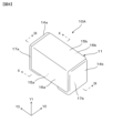
- FIG. 8 is a perspective view schematically showing a multilayer ceramic capacitor 10A in the second embodiment.
- FIG. 9 is a cross-sectional view schematically showing the structure of the multilayer ceramic capacitor 10A shown in FIG. 8 taken along line IX-IX.
- FIG. 10 is a cross-sectional view schematically showing the structure of the multilayer ceramic capacitor 10A shown in FIG. 8 taken along the line XX.
- the second internal electrode 13b is drawn out to the second end surface 17b of the capacitor body 11 and electrically connected to the second external electrode 14b.
- the second internal electrode 13b is not drawn out to the first end surface 17a of the capacitor body 11.
- the first external electrode 14a is provided on at least the first main surface 15a of the surfaces of the capacitor body 11.
- the first external electrode 14a is provided on the first main surface 15a and the first end surface 17a of the surface of the capacitor body 11, as shown in FIGS. 8 to 10. If the first external electrode 14a is provided in such a manner as to cover the plurality of first internal electrodes 13a drawn out to the first end surface 17a of the capacitor body 11, the first external electrode 14a may be provided on the entire first end surface 17a. It may be provided in one part, or it may be provided in a part.
- the second external electrode 14b is provided on at least the first main surface 15a of the surfaces of the capacitor body 11.
- the second external electrode 14b is provided on the first main surface 15a and the second end surface 17b of the surface of the capacitor body 11, as shown in FIGS. 8 to 10. If the second external electrode 14b is provided in such a manner as to cover the plurality of second internal electrodes 13b drawn out to the second end surface 17b of the capacitor body 11, the second external electrode 14b may be provided on the entire second end surface 17b. It may be provided in one part, or it may be provided in a part.
- the multilayer ceramic capacitor 10A in this embodiment the first external electrode 14a and the second external electrode 14b are not provided on the second main surface 15b of the capacitor body 11. Therefore, similarly to the multilayer ceramic capacitor 10 in the first embodiment, the multilayer ceramic capacitor 10A in the second embodiment can also suppress the occurrence of cracks when ultrasonic bonding is performed.
- the multilayer ceramic capacitor 10A in the second embodiment can be manufactured basically by the same manufacturing method as the multilayer ceramic capacitor 10 in the first embodiment.
- FIG. 11 is a perspective view schematically showing a multilayer ceramic capacitor 10B in the third embodiment.
- FIG. 12 is a cross-sectional view schematically showing the structure of the multilayer ceramic capacitor 10B shown in FIG. 11 taken along the line XII-XII.
- FIG. 13 is a cross-sectional view schematically showing the structure of the multilayer ceramic capacitor 10B shown in FIG. 10 taken along the line XIII-XIII.
- the stacking direction is the first direction Y1, as shown in FIGS. 12 and 13. That is, the plurality of dielectric layers 12, the plurality of first internal electrodes 13a, and the plurality of second internal electrodes 13b are stacked in the direction in which the first main surface 15a and the second main surface 15b face each other. There is.
- the multilayer ceramic capacitor 10B in the third embodiment can be manufactured basically by the same manufacturing method as the multilayer ceramic capacitor 10 in the first embodiment.
- FIG. 14 is a perspective view schematically showing a multilayer ceramic capacitor 10C in the fourth embodiment.
- FIG. 15 is a cross-sectional view schematically showing the structure of the multilayer ceramic capacitor 10C shown in FIG. 14 taken along the line XV-XV.
- FIG. 16 is a cross-sectional view schematically showing the structure of the multilayer ceramic capacitor 10C shown in FIG. 14 taken along the line XVI-XVI.
- the stacking direction is the first direction Y1, as shown in FIGS. 15 and 16. That is, the plurality of dielectric layers 12, the plurality of first internal electrodes 13a, and the plurality of second internal electrodes 13b are stacked in the direction in which the first main surface 15a and the second main surface 15b face each other. There is.
- the first external electrode 14a is provided only on the first main surface 15a of the surface of the capacitor body 11, as shown in FIGS. 14 to 16. ing. Furthermore, the second external electrode 14b is provided only on the first main surface 15a of the surfaces of the capacitor body 11.
- the first internal electrode 13a and the second internal electrode 13b are not drawn out to either surface of the capacitor body 11. Not yet. Inside the capacitor body 11, there is a first via conductor 21a for electrically connecting the plurality of first internal electrodes 13a and the first external electrode 14a, and a plurality of second internal electrodes 13b and a first via conductor 21a for electrically connecting the plurality of first internal electrodes 13a and the first external electrode 14a. A second via conductor 21b is provided for electrically connecting the second external electrode 14b.
- the first internal electrode 13a is provided with a first through hole 131 through which the second via conductor 21b is inserted, and the second internal electrode 13b is provided with a first through hole 131 through which the first via conductor 21a is inserted.
- a second through hole 132 is provided for this purpose.
- the first via conductor 21a is provided inside the capacitor body 11 in a manner extending in the first direction Y1, and is electrically connected to the plurality of first internal electrodes 13a.
- the first via conductor 21a passes through a second through hole 132 provided in the second internal electrode 13b, and is insulated from the second internal electrode 13b.
- the second via conductor 21b is provided inside the capacitor body 11 in a manner extending in the first direction Y1, and is electrically connected to the plurality of second internal electrodes 13b.
- the second via conductor 21b passes through a first through hole 131 provided in the first internal electrode 13a, and is insulated from the first internal electrode 13a.
- the second via conductor 21b is exposed at least to the first main surface 15a of the capacitor body 11.
- FIGS. 15 and 16 show a configuration in which the second via conductor 21b is not exposed to the second main surface 15b of the capacitor body 11, it may be exposed.
- the first via conductor 21a and the second via conductor 21b may be made of any material, for example, metals such as Ni, Cu, Ag, Pd, Pt, Fe, Ti, Cr, Sn, or Au, or those metals. Including alloys etc.
- the first external electrode 14a is provided on the first main surface 15a of the capacitor body 11 at a position where the first via conductor 21a is exposed, and is electrically connected to the first via conductor 21a. There is. Since the first via conductor 21a is electrically connected to the plurality of first internal electrodes 13a, the first external electrode 14a is electrically connected to the plurality of first internal electrodes 13a. .
- the second external electrode 14b is provided on the first main surface 15a of the capacitor body 11 at a position where the second via conductor 21b is exposed, and is electrically connected to the second via conductor 21b. There is. Since the second via conductor 21b is electrically connected to the plurality of second internal electrodes 13b, the second external electrode 14b is electrically connected to the plurality of second internal electrodes 13b. .
- the multilayer ceramic capacitor 10C in the fourth embodiment can be manufactured basically by the same manufacturing method as the multilayer ceramic capacitor 10A in the second embodiment and the multilayer ceramic capacitor 10B in the third embodiment. , a step of forming the first via conductor 21a and the second via conductor 21b is required.
- the first via conductor 21a is formed. and a through hole for forming the second via conductor 21b.
- the through hole is formed, for example, by irradiating with a laser beam.
- the formed through holes are filled with a conductive paste for forming the first via conductor 21a and the second via conductor 21b.
- Capacitor body 12 Dielectric layer 13a First internal electrode 13b Second internal electrode 14a First external electrode 14b Second external electrode 15a First main surface of capacitor body 15b Second main surface 16a of capacitor body First side surface 16b of capacitor body Second side surface 17a of capacitor body First end surface 17b of capacitor body Second side surface 20a of capacitor body First bump 20b Second Bump 21a First via conductor 21b Second via conductor 30 Flat area 40 on one main surface of capacitor body Holder 40a Holding surface 41 Substrate 42a First land electrode 42b Second land electrode 141a First metal layer 141b Second metal layer 142a First base electrode layer 142b Second base electrode layer
Landscapes
- Engineering & Computer Science (AREA)
- Power Engineering (AREA)
- Manufacturing & Machinery (AREA)
- Microelectronics & Electronic Packaging (AREA)
- Chemical & Material Sciences (AREA)
- Ceramic Engineering (AREA)
- Inorganic Chemistry (AREA)
- Fixed Capacitors And Capacitor Manufacturing Machines (AREA)
- Ceramic Capacitors (AREA)
Priority Applications (3)
| Application Number | Priority Date | Filing Date | Title |
|---|---|---|---|
| JP2024511818A JP7662104B2 (ja) | 2022-03-30 | 2023-03-17 | 積層セラミックコンデンサ |
| CN202380018164.4A CN118575244A (zh) | 2022-03-30 | 2023-03-17 | 层叠陶瓷电容器 |
| US18/788,282 US20240387111A1 (en) | 2022-03-30 | 2024-07-30 | Multilayer ceramic capacitor |
Applications Claiming Priority (2)
| Application Number | Priority Date | Filing Date | Title |
|---|---|---|---|
| JP2022-055678 | 2022-03-30 | ||
| JP2022055678 | 2022-03-30 |
Related Child Applications (1)
| Application Number | Title | Priority Date | Filing Date |
|---|---|---|---|
| US18/788,282 Continuation US20240387111A1 (en) | 2022-03-30 | 2024-07-30 | Multilayer ceramic capacitor |
Publications (1)
| Publication Number | Publication Date |
|---|---|
| WO2023189718A1 true WO2023189718A1 (ja) | 2023-10-05 |
Family
ID=88201839
Family Applications (1)
| Application Number | Title | Priority Date | Filing Date |
|---|---|---|---|
| PCT/JP2023/010559 Ceased WO2023189718A1 (ja) | 2022-03-30 | 2023-03-17 | 積層セラミックコンデンサ |
Country Status (4)
| Country | Link |
|---|---|
| US (1) | US20240387111A1 (https=) |
| JP (1) | JP7662104B2 (https=) |
| CN (1) | CN118575244A (https=) |
| WO (1) | WO2023189718A1 (https=) |
Citations (5)
| Publication number | Priority date | Publication date | Assignee | Title |
|---|---|---|---|---|
| JPH054451U (ja) * | 1991-07-01 | 1993-01-22 | 株式会社村田製作所 | 積層コンデンサ |
| JPH1167585A (ja) * | 1997-08-11 | 1999-03-09 | Murata Mfg Co Ltd | 積層電子部品 |
| JP2008537328A (ja) * | 2005-04-11 | 2008-09-11 | エプコス アクチエンゲゼルシャフト | 電気的な多層モジュールおよび多層モジュールの製造方法 |
| JP2008302588A (ja) * | 2007-06-07 | 2008-12-18 | Canon Inc | インクジェットヘッド及びインクジェットヘッドの製造方法 |
| JP2009016395A (ja) * | 2007-06-29 | 2009-01-22 | Kyocera Kinseki Corp | 電子部品の接合方法 |
Family Cites Families (12)
| Publication number | Priority date | Publication date | Assignee | Title |
|---|---|---|---|---|
| US7177137B2 (en) * | 2002-04-15 | 2007-02-13 | Avx Corporation | Plated terminations |
| JP5853976B2 (ja) * | 2012-06-12 | 2016-02-09 | 株式会社村田製作所 | 積層コンデンサ |
| US9805867B2 (en) * | 2012-09-19 | 2017-10-31 | Apple Inc. | Acoustically quiet capacitors |
| JP6136916B2 (ja) * | 2013-03-15 | 2017-05-31 | 株式会社村田製作所 | 積層コンデンサ |
| KR102029493B1 (ko) * | 2014-09-29 | 2019-10-07 | 삼성전기주식회사 | 적층 세라믹 커패시터 및 그 실장 기판 |
| JP6623493B2 (ja) * | 2016-03-16 | 2019-12-25 | 大口マテリアル株式会社 | リードフレーム及び半導体装置、並びにそれらの製造方法 |
| CN112908693B (zh) * | 2016-12-01 | 2022-10-21 | 株式会社村田制作所 | 芯片型电子部件 |
| KR102057905B1 (ko) * | 2017-08-31 | 2019-12-20 | 삼성전기주식회사 | 적층형 전자 부품 및 그 실장 기판 |
| KR102473422B1 (ko) * | 2017-10-02 | 2022-12-02 | 삼성전기주식회사 | 적층형 전자 부품 및 그 실장 기판 |
| JP7292958B2 (ja) * | 2019-04-26 | 2023-06-19 | 株式会社村田製作所 | 電子部品の実装構造体 |
| JP2020202220A (ja) * | 2019-06-07 | 2020-12-17 | 株式会社村田製作所 | 積層セラミック電子部品 |
| KR102730020B1 (ko) * | 2019-12-31 | 2024-11-14 | 삼성전기주식회사 | 적층형 전자 부품 및 그 실장 기판 |
-
2023
- 2023-03-17 JP JP2024511818A patent/JP7662104B2/ja active Active
- 2023-03-17 CN CN202380018164.4A patent/CN118575244A/zh active Pending
- 2023-03-17 WO PCT/JP2023/010559 patent/WO2023189718A1/ja not_active Ceased
-
2024
- 2024-07-30 US US18/788,282 patent/US20240387111A1/en active Pending
Patent Citations (5)
| Publication number | Priority date | Publication date | Assignee | Title |
|---|---|---|---|---|
| JPH054451U (ja) * | 1991-07-01 | 1993-01-22 | 株式会社村田製作所 | 積層コンデンサ |
| JPH1167585A (ja) * | 1997-08-11 | 1999-03-09 | Murata Mfg Co Ltd | 積層電子部品 |
| JP2008537328A (ja) * | 2005-04-11 | 2008-09-11 | エプコス アクチエンゲゼルシャフト | 電気的な多層モジュールおよび多層モジュールの製造方法 |
| JP2008302588A (ja) * | 2007-06-07 | 2008-12-18 | Canon Inc | インクジェットヘッド及びインクジェットヘッドの製造方法 |
| JP2009016395A (ja) * | 2007-06-29 | 2009-01-22 | Kyocera Kinseki Corp | 電子部品の接合方法 |
Also Published As
| Publication number | Publication date |
|---|---|
| JP7662104B2 (ja) | 2025-04-15 |
| CN118575244A (zh) | 2024-08-30 |
| US20240387111A1 (en) | 2024-11-21 |
| JPWO2023189718A1 (https=) | 2023-10-05 |
Similar Documents
| Publication | Publication Date | Title |
|---|---|---|
| JP6441961B2 (ja) | 積層型コンデンサおよび実装構造体 | |
| JP6852253B2 (ja) | 積層セラミック電子部品及びその製造方法 | |
| JP5804577B2 (ja) | 積層セラミックキャパシタ、その実装基板及び製造方法 | |
| JP2012248581A (ja) | 積層コンデンサ及び積層コンデンサの製造方法 | |
| KR20180027253A (ko) | 적층형 커패시터 및 그 실장 기판 | |
| CN112908693A (zh) | 芯片型电子部件 | |
| JP7103573B2 (ja) | キャパシタ及びその製造方法 | |
| JP2012212860A (ja) | 積層セラミックコンデンサ | |
| JP2017098524A (ja) | 積層セラミック電子部品及びその製造方法 | |
| JP2018037473A (ja) | 積層セラミックコンデンサ | |
| WO2018146990A1 (ja) | 積層セラミック電子部品 | |
| JP2008091400A (ja) | 積層セラミックコンデンサ及びその製造方法 | |
| CN116153666A (zh) | 多层陶瓷电容器及其制造方法 | |
| JP2017028229A (ja) | 積層型コンデンサおよびその実装構造体 | |
| JP5725678B2 (ja) | 積層セラミック電子部品、その製造方法及びその実装基板 | |
| CN113571337A (zh) | 层叠陶瓷电子部件及其制造方法和电路板 | |
| JP6483400B2 (ja) | 積層型コンデンサおよび実装構造 | |
| KR20130061260A (ko) | 적층 세라믹 전자부품 및 그 제조방법 | |
| JP2014072516A (ja) | 積層セラミック電子部品 | |
| WO2016080350A1 (ja) | 積層型コンデンサ | |
| JP2019117817A (ja) | 積層セラミック電子部品の製造方法 | |
| WO2023189718A1 (ja) | 積層セラミックコンデンサ | |
| JP2022177518A (ja) | 積層セラミックコンデンサ | |
| JP2018148059A (ja) | 熱収縮チューブ付き積層セラミック電子部品およびその実装方法 | |
| JPH1140460A (ja) | 積層セラミック電子部品 |
Legal Events
| Date | Code | Title | Description |
|---|---|---|---|
| 121 | Ep: the epo has been informed by wipo that ep was designated in this application |
Ref document number: 23779735 Country of ref document: EP Kind code of ref document: A1 |
|
| WWE | Wipo information: entry into national phase |
Ref document number: 202380018164.4 Country of ref document: CN |
|
| ENP | Entry into the national phase |
Ref document number: 2024511818 Country of ref document: JP Kind code of ref document: A |
|
| NENP | Non-entry into the national phase |
Ref country code: DE |
|
| 122 | Ep: pct application non-entry in european phase |
Ref document number: 23779735 Country of ref document: EP Kind code of ref document: A1 |