WO2023175799A1 - 研削盤 - Google Patents
研削盤 Download PDFInfo
- Publication number
- WO2023175799A1 WO2023175799A1 PCT/JP2022/012059 JP2022012059W WO2023175799A1 WO 2023175799 A1 WO2023175799 A1 WO 2023175799A1 JP 2022012059 W JP2022012059 W JP 2022012059W WO 2023175799 A1 WO2023175799 A1 WO 2023175799A1
- Authority
- WO
- WIPO (PCT)
- Prior art keywords
- reaction
- grinding
- reaction force
- motor
- torque
- Prior art date
Links
- 238000001514 detection method Methods 0.000 claims description 32
- 230000007423 decrease Effects 0.000 claims description 6
- 238000000034 method Methods 0.000 description 30
- 230000008569 process Effects 0.000 description 29
- 239000010720 hydraulic oil Substances 0.000 description 10
- 230000001276 controlling effect Effects 0.000 description 8
- 230000008859 change Effects 0.000 description 5
- 239000000463 material Substances 0.000 description 5
- 238000010586 diagram Methods 0.000 description 4
- 238000003825 pressing Methods 0.000 description 4
- 230000004044 response Effects 0.000 description 2
- 230000035945 sensitivity Effects 0.000 description 2
- 239000006061 abrasive grain Substances 0.000 description 1
- 230000009471 action Effects 0.000 description 1
- 239000011230 binding agent Substances 0.000 description 1
- 239000000470 constituent Substances 0.000 description 1
- 230000000694 effects Effects 0.000 description 1
- 230000006872 improvement Effects 0.000 description 1
- 238000009434 installation Methods 0.000 description 1
- 230000036544 posture Effects 0.000 description 1
- 230000001105 regulatory effect Effects 0.000 description 1
- 238000004513 sizing Methods 0.000 description 1
Images


Classifications
-
- B—PERFORMING OPERATIONS; TRANSPORTING
- B24—GRINDING; POLISHING
- B24B—MACHINES, DEVICES, OR PROCESSES FOR GRINDING OR POLISHING; DRESSING OR CONDITIONING OF ABRADING SURFACES; FEEDING OF GRINDING, POLISHING, OR LAPPING AGENTS
- B24B41/00—Component parts such as frames, beds, carriages, headstocks
- B24B41/02—Frames; Beds; Carriages
-
- B—PERFORMING OPERATIONS; TRANSPORTING
- B24—GRINDING; POLISHING
- B24B—MACHINES, DEVICES, OR PROCESSES FOR GRINDING OR POLISHING; DRESSING OR CONDITIONING OF ABRADING SURFACES; FEEDING OF GRINDING, POLISHING, OR LAPPING AGENTS
- B24B47/00—Drives or gearings; Equipment therefor
- B24B47/02—Drives or gearings; Equipment therefor for performing a reciprocating movement of carriages or work- tables
- B24B47/04—Drives or gearings; Equipment therefor for performing a reciprocating movement of carriages or work- tables by mechanical gearing only
-
- B—PERFORMING OPERATIONS; TRANSPORTING
- B24—GRINDING; POLISHING
- B24B—MACHINES, DEVICES, OR PROCESSES FOR GRINDING OR POLISHING; DRESSING OR CONDITIONING OF ABRADING SURFACES; FEEDING OF GRINDING, POLISHING, OR LAPPING AGENTS
- B24B47/00—Drives or gearings; Equipment therefor
- B24B47/20—Drives or gearings; Equipment therefor relating to feed movement
-
- B—PERFORMING OPERATIONS; TRANSPORTING
- B24—GRINDING; POLISHING
- B24B—MACHINES, DEVICES, OR PROCESSES FOR GRINDING OR POLISHING; DRESSING OR CONDITIONING OF ABRADING SURFACES; FEEDING OF GRINDING, POLISHING, OR LAPPING AGENTS
- B24B5/00—Machines or devices designed for grinding surfaces of revolution on work, including those which also grind adjacent plane surfaces; Accessories therefor
- B24B5/02—Machines or devices designed for grinding surfaces of revolution on work, including those which also grind adjacent plane surfaces; Accessories therefor involving centres or chucks for holding work
Definitions
- the present disclosure relates to a grinding machine.
- grinding machines There are two types of grinding machines: automatic machines that grind automatically according to a program, and manually operated machines that grind manually by operating a manual rotation handle. There are also grinding machines that have both the functions of an automatic machine and a manual machine.
- Patent Document 1 describes a configuration in which a manually operable grinding machine moves a movable body based on an electric signal corresponding to the amount of rotation of a manual rotation handle without using hydraulic oil.
- the manual rotation handle is provided with a rotational torque variable means for varying the torque required for rotation, and the rotational torque variable means is controlled according to the proximity state of the workpiece and the grinding wheel. Therefore, even in a configuration that does not use hydraulic oil, the operator can detect contact between the workpiece and the grinding wheel by increasing the torque of the manual rotation handle when the workpiece and the grinding wheel come into contact. It is possible to perform high-precision grinding.
- the rotation torque variable means is configured to increase the rotation torque of the manual rotation handle by pressing a pressing member against a plate integrated with the manual rotation handle.
- the flow rate of compressed air is adjusted by controlling a pressure regulating electromagnetic valve depending on the proximity between the workpiece and the grinding wheel, and a pressing force is applied to the pressing member in accordance with the flow rate of compressed air.
- the rotational torque variable means determines the contact state and non-contact state between the workpiece and the grinding wheel based on the proximity detection signal, and switches the torque applied to the manual rotation handle depending on the contact state and the non-contact state. There is. Further, the applied torque is kept constant in the contact state, or the cutting depth of the grinding wheel is detected based on the proximity detection signal in the contact state, and the applied torque is controlled according to the cutting depth.
- the conventional rotational torque variable means has room for improvement compared to a structure using hydraulic oil.
- the present disclosure has been made in view of such problems, and makes it possible to apply a load to a manually rotating handle with high precision similar to a manually operated machine using hydraulic oil, and to apply a load to the manually rotating handle.
- the present invention aims to provide a grinding machine that can increase the degree of freedom in loading.
- One aspect of the present disclosure includes a grinding wheel for grinding a workpiece; a moving body that moves the grinding wheel relative to the workpiece; a moving motor that moves the moving body; a manual rotation handle for controlling the position of the moving body; a reaction motor attached to the manual rotation handle and configured to apply a reaction torque to the manual rotation handle when the manual rotation handle is rotating; a control device that controls the movement motor according to the rotation angle of the manual rotation handle, and controls the reaction motor so as to generate the reaction torque according to the magnitude of grinding resistance during grinding;
- the grinding machine is equipped with
- the reaction torque is applied to the manual rotation handle by the reaction motor attached to the manual rotation handle. Therefore, by controlling the reaction motor, there is a high degree of freedom in applying reaction torque to the manually rotating handle.
- the control device controls the reaction motor to generate reaction torque according to the magnitude of grinding resistance during grinding. Therefore, when the operator is operating the manual rotation handle, the operator can feel a load from the manual rotation handle that corresponds to the magnitude of the grinding resistance during grinding.
- the magnitude of the grinding resistance varies depending on not only the depth of cut but also the material of the workpiece and the sharpness of the grinding wheel.
- the reaction torque changes depending on the material of the workpiece and the sharpness of the grinding wheel, in addition to the depth of cut. Therefore, the load depending on the magnitude of the grinding resistance that the operator feels from the manually rotating handle can be the same as that of a manually operated machine that uses hydraulic oil, or the load that corresponds to the magnitude of the grinding resistance that the operator feels from the manually rotating handle.
- the load can be a further adjusted load. In this way, it becomes possible for the operator to highly accurately apply a load to the manually rotating handle that is being operated, and it is possible to perform highly accurate grinding using the manually rotating handle.
- FIG. 1 is a plan view of the grinding machine of Embodiment 1.
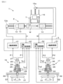
- FIG. 2 is a diagram showing the configuration of a handle unit and a control device in the grinding machine of Embodiment 1.
- FIG. 3 is a front view of the handle unit.
- 7 is a flowchart showing reaction force control processing by a reaction force control section of the control device in the first embodiment.
- 5 is a flowchart showing the initial reaction torque generation process in FIG. 4.
- FIG. 5 is a flowchart showing reaction torque continuation generation processing in FIG. 4.
- FIG. It is a graph showing relational information used for determining reaction force torque, and is a graph showing reaction force torque according to the drive current and gain value of the moving motor.
- FIG. 7 is a diagram showing the behavior of the rotation speed of the manual rotation handle, the moving speed of the grindstone head, and the reaction torque when the manual rotation handle is operated.
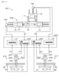
- FIG. 7 is a diagram showing the configuration of a handle unit and a control device in a grinding machine according to a second embodiment.
- 12 is a flowchart showing reaction torque continuation generation processing among reaction force control processing by a reaction force control section of a control device in Embodiment 2. It is a graph showing relational information used to determine reaction force torque, and is a graph showing reaction force torque according to a detection value and a gain value of an AE sensor.
- FIG. 7 is a diagram showing the configuration of a handle unit and a control device in a grinding machine according to a third embodiment.
- 11 is a flowchart showing reaction force control processing by a reaction force control section of a control device in Embodiment 3.
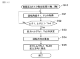
- 14 is a flowchart showing the initial reaction torque generation process in FIG. 13.
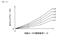
- 12 is a flowchart showing reaction force control processing by a reaction force control section of a control device in Embodiment 4. It is a graph showing relational information used for determining reaction force torque, and is a graph showing reaction force torque according to the drive current and gain value of the moving motor.
- (Embodiment 1) Configuration of Grinding Machine 1
- the configuration of the grinding machine 1 of this embodiment will be described with reference to FIG. 1.
- the grinding machine 1 rotates the workpiece W and rotates the grinding wheel T, and moves the workpiece W and the grinding wheel T relative to each other.
- the modes of grinding include (a) a mode in which the outer circumferential surface of the workpiece W is ground while moving the grinding wheel T relatively in the radial direction (X-axis direction) of the workpiece W, and (b) a mode in which the grinding wheel T is moved in the radial direction (X-axis direction) of the workpiece W.
- the grinding machine 1 is a cylindrical grinding machine, but various configurations such as a cam grinding machine, a surface grinding machine, etc. can be applied. Further, in this embodiment, the grinding machine 1 is a table traverse type grinding machine, but a grindstone head traverse type grinding machine can also be applied.
- the grinding machine 1 includes a grinding machine main body 2 and a control device 3.
- the grinding machine main body 2 includes a bed 11, a table 12, a headstock 13, a tailstock 14, a grindstone head 15, a Z-axis handle unit 16, and an X-axis handle unit 17.
- the table 12 constitutes a Z-axis moving body that moves the grinding wheel T relative to the workpiece W in the Z-axis direction.
- the grindstone head 15 constitutes an X-axis moving body that moves the grindstone T relative to the workpiece W in the X-axis direction.
- the grinding machine main body 2 may be provided with a sizing device, a rest device, a grinding wheel correction device, and the like.
- the bed 11 is placed on the installation surface.
- a Z-axis guide 11a extending in the Z-axis direction and an X-axis guide 11b extending in the X-axis direction are formed on the top surface of the bed 11.
- the Z-axis guide 11a is formed on the front side in the X-axis direction (lower side in FIG. 1), which is the front side of the machine.
- the X-axis guide 11b is formed on the back side of the machine (upper side in FIG. 1) than the Z-axis guide 11a.
- the table 12 (Z-axis moving body) is arranged on the upper surface of the bed 11 so as to be movable in the Z-axis direction while being guided by the Z-axis guide 11a of the bed 11.
- the table 12 is configured to be movable via a ball screw device by driving a motor 12a (Z-axis moving motor) provided on the bed 11. That is, the motor 12a moves the table 12 in the Z-axis direction.
- the table 12 may be driven by a linear motor instead of the motor 12a and the ball screw device.
- the headstock 13 includes a headstock main body 13a, a main shaft 13b, a motor 13c, and a center member 13d.
- the headstock main body 13a is fixed to the upper surface of the table 12.
- the main shaft 13b is rotatably supported by the headstock main body 13a around the Z-axis.
- the motor 13c is provided on the headstock main body 13a, and rotates the main shaft 13b.
- the center member 13d is attached to the tip of the main shaft 13b and supports one end of the workpiece W. That is, by rotationally driving the motor 13c, the workpiece W is rotationally driven around the central axis of the workpiece W.
- the headstock 13 is exemplified to have a structure in which one end of the workpiece W is supported by the center member 13d, but a chuck can also be applied in place of the center member 13d.
- the tailstock 14 is arranged on the upper surface of the table 12 at a position facing the headstock 13 in the Z-axis direction.
- the tailstock 14 supports the other end of the workpiece W in the axial direction, and supports the workpiece W so as to be rotatable around the Z-axis.
- the tailstock 14 includes a tailstock main body 14a, a ram 14b, and a center member 14c.
- the tailstock main body 14a is fixed to the upper surface of the table 12.
- the ram 14b is provided on the tailstock body 14a so as to be movable in the Z-axis direction. In other words, the ram 14b is provided so that its protrusion amount can be changed with respect to the tailstock main body 14a.
- the center member 14c is attached to the tip of the ram 14b and supports the other end of the workpiece W. In this way, the workpiece W is rotatably supported at both ends by the headstock 13 and the tailstock 14. Note that the workpiece W may be cantilevered only by the headstock 13. Further, in the tailstock 14, the tailstock main body 14a may be configured to be movable in the Z-axis direction with respect to the table 12. In this case, the ram 14b becomes unnecessary.
- the grindstone head 15 (X-axis moving body) is arranged on the upper surface of the bed 11 so as to be movable in the X-axis direction while being guided by the X-axis guide 11b of the bed 11.
- the grindstone head 15 is configured to be movable via a ball screw device by driving a motor 15a (X-axis moving motor) provided on the bed 11. That is, the motor 15a moves the grindstone head 15 in the X-axis direction.
- the grindstone head 15 may be driven by a linear motor instead of the motor 15a and the ball screw device.
- the whetstone head 15 includes a rotatably provided whetstone wheel T.
- the grinding wheel T is driven by a motor 15b provided on the grinding wheel head 15, and rotates via a belt 15c.
- the grinding wheel T is a tool for grinding the workpiece W, and is composed of a plurality of abrasive grains fixed with a binder.
- the Z-axis handle unit 16 is provided on the front side of the bed 11, and in this embodiment, it is provided on the left side of the center in the left-right direction.
- the Z-axis handle unit 16 includes a Z-axis manual rotation handle 21.
- the Z-axis manual rotation handle 21 is configured to be manually operable by an operator, and is a member for manually operating the position of the table 12 as a Z-axis moving body.
- the Z-axis handle unit 16 further includes a Z-axis reaction force gain value adjustment section 22.
- the Z-axis reaction force gain value adjustment unit 22 is configured to be manually operable by an operator, and is configured to be able to adjust a gain value G1 regarding the reaction torque to be applied to the Z-axis manual rotation handle 21.
- the X-axis handle unit 17 is provided on the front side of the bed 11, and in this embodiment, it is provided on the right side of the center in the left-right direction.
- the X-axis handle unit 17 includes an X-axis manual rotation handle 31.
- the X-axis manual rotation handle 31 is configured to be manually operable by an operator, and is a member for manually controlling the position of the grindstone head 15 as an X-axis moving body.
- the X-axis handle unit 17 further includes an X-axis reaction force gain value adjustment section 32.
- the X-axis reaction force gain value adjustment unit 32 is configured to be manually operable by an operator, and is configured to be able to adjust a gain value G2 regarding the reaction torque to be applied to the X-axis manual rotation handle 31.
- the control device 3 controls each drive device that makes up the grinding machine body 2. Specifically, the control device 3 controls the motor 12a (Z-axis moving motor) according to the rotation angle of the Z-axis manual rotation handle 21, and controls the position of the table 12 (Z-axis moving body) in the Z-axis direction. . The control device 3 controls the motor 15a (X-axis moving motor) according to the rotation angle of the X-axis manual rotation handle 31, and controls the position of the grindstone head 15 (X-axis moving body) in the X-axis direction. That is, the control device 3 controls the positions of the table 12 and the grindstone head 15, which serve as movable bodies that move the grinding wheel T relative to the workpiece W, by controlling the motors 12a and 15a. Further, the control device 3 controls the motor 13c of the headstock 13 in order to control the rotation of the workpiece W. The control device 3 controls the motor 15b of the grinding wheel head 15 in order to control the rotation of the grinding wheel T.
- handle units 16, 17 The detailed configuration of handle units 16, 17 will be described with reference to FIGS. 2 and 3. As shown in FIG. 2, the Z-axis handle unit 16 and the X-axis handle unit 17 have the same constituent elements, except for the members to be operated. In the following, both elements will be explained unless a special axis name is given.
- the handle units 16 and 17 include manual rotation handles 21 and 31, reaction force gain value adjustment units 22 and 32, input side shaft members 23 and 33, output side shaft members 24 and 34, torsion bars 25 and 35, and a reaction force motor 26. , 36, angle detection sensors 27, 37, and torque sensors 28, 38.
- the manual rotation handles 21 and 31 are members for operating the position of the table 12 or the grindstone head 15 as a moving body. As shown in FIGS. 2 and 3, the manual rotation handles 21 and 31 include, for example, an annular main body portion and a grip portion fixed to the main body portion. The operator can rotate the manual rotation handles 21, 31 by grasping the grip portion. Note that the manual rotation handles 21 and 31 only need to be configured to be rotatable, and instead of the annular main body portion, for example, a rod-shaped arm extending in the radial direction may be used. In this case, the manual rotation handles 21, 31 are formed, for example, in an L-shape.
- the input side shaft members 23 and 33 are integrally provided with the manual rotation handles 21 and 31, and are rotatably supported by the bed 11 or a member fixed to the bed 11.
- the rotation center axes of the input side shaft members 23 and 33 are coaxial with the rotation center axes of the manual rotation handles 21 and 31.
- the output side shaft members 24 and 34 are supported by the bed 11 or a member fixed to the bed 11 so as to be rotatable relative to the input side shaft members 23 and 33.
- the rotation center axes of the output side shaft members 24 and 34 are coaxial with the rotation center axes of the input side shaft members 23 and 33.
- One end of the torsion bars 25, 35 is connected to the input side shaft members 23, 33, and the other end is connected to the output side shaft members 24, 34. Therefore, when the input side shaft members 23, 33 are rotated, the torsion bars 25, 35 are twisted, and the output side shaft members 24, 34 are rotated.
- the reaction motors 26 and 36 are attached to the output side shaft members 24 and 34. That is, the reaction motors 26, 36 are attached to the manual rotation handles 21, 31 via the output shaft members 24, 34, the torsion bars 25, 35, and the input shaft members 23, 33.
- the reaction motors 26, 36 are configured to apply reaction torques Tb1, Tb2 to the manual rotation handle while the manual rotation handle is rotating. That is, by driving the reaction motors 26 and 36, reaction torques Tb1 and Tb2 are applied to the output shaft members 24 and 34 fixed to the drive shafts of the reaction motors 26 and 36, and the torsion bar 25 and 35 and the input side shaft members 23, 33, the reaction torques Tb1, Tb2 are transmitted to the manual rotation handles 21, 31.
- the angle detection sensors 27 and 37 are attached to the reaction motors 26 and 36, and detect the angles ⁇ 1 and ⁇ 2 of the drive shafts of the reaction motors 26 and 36. That is, the angle detection sensors 27 and 37 substantially detect the rotation angles ⁇ 1 and ⁇ 2 of the manual rotation handles 21 and 31.
- the angle detection sensors 27 and 37 are, for example, encoders.
- the torque sensors 28 and 38 detect that operating torques Ta1 and Ta2 are applied to the manual rotation handles 21 and 31 by the operator.
- the torque sensors 28 and 38 can detect the operating torques Ta1 and Ta2 by detecting the twisted state of the torsion bars 25 and 35.
- the torque sensors 28 and 38 use, for example, Hall IC type torque sensors, and are provided on the input side shaft members 23 and 33 and the output side shaft members 24 and 34. Since the Hall IC type torque sensor is well known, detailed explanation thereof will be omitted. As the torque sensors 28 and 38, torque sensors having other configurations may also be applied.
- the reaction force gain value adjustment units 22 and 32 are configured to be manually operable by the operator, and adjust the gain values G1, G1, and G1 regarding the reaction torques Tb1 and Tb2 to be applied to the manual rotation handles 21 and 31, respectively.
- G2 is configured to be adjustable.
- the reaction torques Tb1 and Tb2 are controlled by the control device 3.
- the reaction force gain value adjustment units 22 and 32 are, for example, adjustment knob members configured to be manually operable.
- the adjustment knob member is, for example, a dial type, and is configured to be settable in a plurality of stages.
- the adjustment knob member may be composed of an adjustment button, an adjustment lever, or the like.
- the adjustment button is composed of a plurality of buttons.
- the adjustment lever is configured to take a plurality of postures.
- Control Device 3 Configuration of Control Device 3
- the configuration of the control device 3 will be described with reference to FIG. 2.
- the control related to the operation of the manual rotation handles 21 and 31 in the control device 3 will be explained.
- the control device 3 includes a Z-axis control section 41, a Z-axis reaction force control section 42, an X-axis control section 51, and an X-axis reaction force control section 52 as elements related to the operation of the manual rotation handles 21 and 31.
- the Z-axis control unit 41 controls the motor 12a (Z-axis moving motor) according to the rotation angle ⁇ 1 of the Z-axis manual rotation handle 21, and controls the position of the table 12 (Z-axis moving body) in the Z-axis direction.
- the Z-axis reaction force control unit 42 controls the Z-axis reaction force motor 26 to generate a Z-axis reaction torque Tb1 according to the magnitude of grinding resistance during grinding.
- the Z-axis reaction force control unit 42 sets the magnitude of the drive current I1 of the motor 12a during grinding as the magnitude of the grinding resistance, and adjusts the Z-axis reaction torque according to the magnitude of the drive current I1 of the motor 12a.
- the Z-axis reaction force motor 26 is controlled so that the Z-axis reaction force motor 26 generates Tb1.
- the Z-axis reaction force control unit 42 controls the Z-axis reaction torque Tb1 according to the magnitude of the drive current I1 of the motor 12a during non-grinding. is generated in the Z-axis reaction force motor 26.
- the Z-axis reaction force control unit 42 controls the rotation angle ⁇ 1 of the Z-axis manual rotation handle 21 detected by the Z-axis angle detection sensor 27, the Z-axis operating torque Ta1 detected by the Z-axis torque sensor 28, The gain value G1 set by the Z-axis reaction force gain value adjustment section 22 and the drive current I1 of the motor 12a are acquired.
- the Z-axis reaction force control unit 42 controls the Z-axis reaction force motor 26 to cause the Z-axis manual rotation handle 21 to generate a Z-axis reaction torque Tb1 based on the acquired information.
- the control device 3 uses the detection of the operation torque Ta1 by the Z-axis torque sensor 28 as a trigger to cause the Z-axis reaction force motor 26 to generate a Z-axis reaction torque Tb1. At this time, the control device 3 determines the rotation direction of the Z-axis manual rotation handle 21 based on the detected value of the Z-axis angle detection sensor 27. Then, the control device 3 controls the Z-axis reaction force motor 26 to generate the Z-axis reaction torque Tb1 in the opposite direction to the determined rotation direction of the Z-axis manual rotation handle 21. Further, the control device 3 causes the Z-axis reaction force motor 26 to stop generating the Z-axis reaction torque Tb1 when the Z-axis operation torque Ta1 decreases to a predetermined value or less.
- control device 3 generates the Z-axis reaction torque Tb1 obtained based on the magnitude of the grinding resistance during grinding and the gain value G1 adjusted by the Z-axis reaction force gain value adjustment section 22.
- the Z-axis reaction force motor 26 is controlled.
- the X-axis control unit 51 controls the motor 15a (X-axis moving motor) according to the rotation angle ⁇ 2 of the X-axis manual rotation handle 31, and controls the position of the grindstone head 15 (X-axis moving body) in the X-axis direction. .
- the X-axis reaction force control unit 52 controls the X-axis reaction force motor 36 to generate an X-axis reaction torque Tb2 according to the magnitude of grinding resistance during grinding.
- the X-axis reaction force control unit 52 sets the magnitude of the drive current I2 of the motor 15a as the magnitude of the grinding resistance during grinding, and generates an X-axis reaction force torque corresponding to the magnitude of the drive current I2 of the motor 15a.
- the X-axis reaction force motor 36 is controlled to cause the X-axis reaction force motor 36 to generate Tb2. Furthermore, when the X-axis manual rotation handle 31 is rotating during non-grinding, the X-axis reaction force control unit 52 controls the is generated in the X-axis reaction force motor 36.
- the X-axis reaction force control unit 52 controls the rotation angle ⁇ 2 of the X-axis manual rotation handle 31 detected by the X-axis angle detection sensor 37, the X-axis operating torque Ta2 detected by the X-axis torque sensor 38, The gain value G2 set by the X-axis reaction force gain value adjustment section 32 and the drive current I2 of the motor 15a are acquired.
- the X-axis reaction force control unit 52 controls the X-axis reaction force motor 36 to cause the X-axis manual rotation handle 31 to generate an X-axis reaction torque Tb2 based on the acquired information.
- the control device 3 causes the X-axis reaction force motor 36 to generate an X-axis reaction torque Tb2 using the detection of the operating torque Ta2 by the X-axis torque sensor 38 as a trigger. At this time, the control device 3 determines the rotation direction of the X-axis manual rotation handle 31 based on the detection value of the X-axis angle detection sensor 37. Then, the control device 3 controls the X-axis reaction force motor 36 to generate the X-axis reaction torque Tb2 in the opposite direction to the determined rotational direction of the X-axis manual rotation handle 31. Further, the control device 3 causes the X-axis reaction force motor 36 to stop generating the X-axis reaction torque Tb2 when the X-axis operation torque Ta2 decreases to a predetermined value Th1 or less.
- control device 3 Furthermore, the control device 3 generates the X-axis reaction torque Tb2 obtained based on the magnitude of the grinding resistance during grinding and the gain value G2 adjusted by the X-axis reaction force gain value adjustment section 32.
- the X-axis reaction force motor 36 is controlled.
- the processing of the reaction force control units 42, 52 of the control device 3 will be described with reference to FIGS. 4 to 7.
- the reaction force control units 42 and 52 determine whether the mode is manual operation mode (S1). If it is not the manual operation mode (S1: No), the process returns.
- the reaction force control units 42, 52 determine whether the reaction force motors 26, 36 are stopped (S2). If the reaction force motors 26, 36 are stopped (S2: Yes), the reaction force control units 42, 52 execute initial reaction torque generation processing (S3), and return the process. The initial reaction torque generation process S3 will be described later.
- reaction force control units 42, 52 acquire the operating torques Ta1, Ta2 (S4). Subsequently, the reaction force control units 42 and 52 determine whether the operating torques Ta1 and Ta2 are equal to or less than a predetermined value Th1 (S5). If the operating torques Ta1, Ta2 are not equal to or less than the predetermined value Th1 (S5: No), the reaction force control units 42, 52 execute reaction torque continuation generation processing (S6). The reaction torque continuation generation process S6 will be described later.
- reaction force control units 42 and 52 execute reaction torque stop processing (S7).
- the reaction torque stop process S7 is a process for stopping the generation of reaction torques Tb1 and Tb2 by the reaction motors 26 and 36.
- the reaction force control units 42 and 52 acquire operating torques Ta1 and Ta2 (S11). Subsequently, the reaction force control units 42 and 52 determine whether the operating torques Ta1 and Ta2 are larger than a predetermined value Th2 (S12). S11 is repeated until the operating torques Ta1 and Ta2 become larger than the predetermined value Th2 (S12: No).
- the reaction force control units 42 and 52 determine the reaction torques Tb1 and Tb2 (S13).
- the reaction torques Tb1 and Tb2 at this time are a preset value A, as shown in FIG.
- the reaction force control units 42 and 52 obtain the rotation angles ⁇ 1 and ⁇ 2 (S14). Then, the reaction force control units 42 and 52 calculate the rotation direction of the manual rotation handles 21 and 31 based on the rotation angles ⁇ 1 and ⁇ 2 (S15). Subsequently, the reaction force control units 42 and 52 generate the determined reaction torques Tb1 and Tb2 in the reaction direction that is the reverse direction of the calculated rotational direction (S16). Then, the process ends.
- reaction force control units 42 and 52 acquire the drive currents I1 and I2 of the motors 12a and 15a (S21). Subsequently, the reaction force control units 42 and 52 obtain gain values G1 and G2 (S22). Subsequently, the reaction force control units 42, 52 determine reaction torques Tb1, Tb2 based on the magnitudes of the drive currents I1, I2 of the motors 12a, 15a and the gain values G1, G2 (S23).
- reaction torques Tb1 and Tb2 become larger as the magnitudes of the drive currents I1 and I2 of the motors 12a and 15a become larger.
- the reaction torques Tb1 and Tb2 are set to monotonically increase in a polygonal manner with respect to the magnitude of the drive currents I1 and I2.
- the reaction torques Tb1 and Tb2 may be set to increase monotonically in a curved manner with respect to the magnitude of the drive currents I1 and I2.
- the reaction torques Tb1 and Tb2 are set to different values depending on the gain values G1 and G2. For example, the smaller the Lv of the gain values G1, G2, the smaller the reaction torques Tb1, Tb2, and the larger the Lv of the gain values G1, G2, the larger the reaction torques Tb1, Tb2. There is.
- the reaction force control units 42 and 52 obtain the rotation angles ⁇ 1 and ⁇ 2 (S24). Then, the reaction force control units 42 and 52 calculate the rotation direction of the manual rotation handles 21 and 31 based on the rotation angles ⁇ 1 and ⁇ 2 (S25). Subsequently, the reaction force control units 42 and 52 generate the determined reaction torques Tb1 and Tb2 in the reaction direction that is the reverse direction of the calculated rotational direction (S26). Then, the process ends.
- the initial state is a state in which the grinding wheel T is separated from the workpiece W in the It is assumed that an action is performed to separate the object W from the object W.
- grinding in the X-axis direction will be described, substantially the same behavior occurs when grinding in the Z-axis direction.
- the operator starts rotating the X-axis manual rotation handle 31 in one direction at a low speed.
- the X-axis control unit 51 controls the motor 15a according to the rotation angle ⁇ 2 detected by the angle detection sensor 37.
- the grindstone head 15 starts moving toward the workpiece W at a low speed in the X-axis direction.
- reaction torque Tb2 can be generated.
- the grindstone head 15 After the grindstone head 15 starts to move, based on the drive current I2 of the motor 15a, the gain value G2 set by the X-axis reaction force gain value adjustment section 32, and the relationship shown in FIG. X-axis reaction torque Tb2 is determined. Then, the X-axis reaction motor 36 is controlled to generate the determined X-axis reaction torque Tb2.
- the operator gradually increases the rotation speed of the X-axis manual rotation handle 31 in one direction.
- the grindstone head 15 moves toward the workpiece W at high speed in the X-axis direction.
- the motor 15a is controlled by the X-axis control unit 51, so that the grindstone head 15 moves toward the workpiece W at high speed in the X-axis direction.
- a reaction torque Tb2 is applied to the X-axis manual rotation handle 31 according to the relationship shown in FIG.
- the operator ends the spark-out and starts rotating the X-axis manual rotation handle 31 in the other direction.
- the operator first rotates at a low speed and then at a high speed.
- the moving speed of the grindstone head 15 and the X-axis reaction torque Tb2 generated by the X-axis reaction force motor 36 behave as shown in FIG.
- the operator stops the rotation of the X-axis manual rotation handle 31.
- reaction torques Tb1 and Tb2 are applied to the manual rotation handles 21 and 31 by the reaction motors 26 and 36 attached to the manual rotation handles 21 and 31, respectively. Therefore, by controlling the reaction motors 26 and 36, there is a high degree of freedom in applying reaction torques Tb1 and Tb2 to the manual rotation handles 21 and 31.
- control device 3 controls the reaction motors 26 and 36 to generate reaction torques Tb1 and Tb2 according to the magnitude of grinding resistance during grinding. Therefore, when the operator is operating the manual rotation handles 21, 31, the operator can feel the load from the manual rotation handles 21, 31 according to the magnitude of the grinding resistance during grinding.
- the magnitude of the grinding resistance varies depending on the material of the workpiece W and the sharpness of the grinding wheel T in addition to the depth of cut.
- the reaction torques Tb1 and Tb2 vary depending on the material of the workpiece W and the sharpness of the grinding wheel T in addition to the depth of cut.
- the load depending on the magnitude of the grinding resistance that the operator feels from the manual rotary handles 21, 31 can be the same as that of a manually operated machine using hydraulic oil, or a The load on the driving machine can be further adjusted. In this way, it becomes possible for the operator to apply a load with high accuracy to the manual rotation handles 21, 31 that are being operated, and it is possible to perform highly accurate grinding using the manual rotation handles 21, 31.
- control device 3 sets the magnitude of the drive currents I1, I2 of the motors 12a, 15a as the magnitude of the grinding resistance during grinding, and generates a reaction torque corresponding to the magnitude of the drive currents I1, I2 of the motors 12a, 15a.
- the reaction force motors 26 and 36 are controlled so that the reaction force motors 26 and 36 generate Tb1 and Tb2. In this way, by using the magnitudes of the drive currents I1 and I2 of the motors 12a and 15a, desired control can be performed easily and reliably.
- the control device 3 when the manual rotation handles 21 and 31 are rotating during non-grinding, the control device 3 generates reaction torques Tb1 and Tb2 corresponding to the magnitudes of drive currents I1 and I2 of the motors 12a and 15a during non-grinding. is generated in the reaction force motors 26, 36. That is, the reaction torques Tb1 and Tb2 can be applied to the manual rotation handles 21 and 31 not only during grinding but also during non-grinding. Therefore, the operator can feel the reaction torques Tb1 and Tb2 while operating the manual rotation handles 21 and 31.
- the grinding machine 1 further includes torque sensors 28 and 38 that detect that the operating torques Ta1 and Ta2 are applied to the manual rotation handles 21 and 31. Then, the control device 3 causes the reaction motors 26 and 36 to generate reaction torques Tb1 and Tb2 using the detection of the operating torques Ta1 and Ta2 by the torque sensors 28 and 38 as a trigger. By using the detection of the operating torques Ta1 and Ta2 by the torque sensors 28 and 38 as a trigger, the reaction torques Tb1 and Tb2 can be applied to the manual rotation handles 21 and 31 with high response. In other words, the sensitivity of the manual rotation handles 21, 31 can be improved.
- control device 3 causes the reaction motors 26 and 36 to stop generating the reaction torques Tb1 and Tb2 when the operating torques Ta1 and Ta2 decrease to a predetermined value Th1 or less. In this manner, by using the operating torques Ta1 and Ta2, when the manual rotation handles 21 and 31 are stopped, generation of the reaction torques Tb1 and Tb2 can be stopped with high response. In other words, the sensitivity of the manual rotation handles 21, 31 can be improved.
- the grinding machine 1 further includes angle detection sensors 27 and 37 that detect rotation angles ⁇ 1 and ⁇ 2 of the manual rotation handles 21 and 31. Then, the control device 3 determines the rotation direction of the manual rotation handles 21, 31 based on the detected values ⁇ 1, ⁇ 2 of the angle detection sensors 27, 37, and rotates the manual rotation handles 21, 31 in the opposite direction to the determined rotation direction of the manual rotation handles 21, 31.
- the reaction motors 26 and 36 are controlled to generate reaction torques Tb1 and Tb2. Therefore, the directions in which the reaction torques Tb1 and Tb2 are generated can be reliably obtained.
- the grinding machine 1 further includes reaction force gain value adjustment units 22 and 32 configured to be able to adjust gain values G1 and G2 regarding reaction force torques Tb1 and Tb2. Then, the control device 3 generates reaction force torques Tb1 and Tb2 obtained based on the magnitude of the grinding resistance during grinding and the gain values G1 and G2 adjusted by the reaction force gain value adjustment units 22 and 32.
- the reaction motors 26 and 36 are controlled so as to For example, the operator can adjust the magnitudes of the reaction torques Tb1 and Tb2 to his/her preference. In this way, the reaction torques Tb1 and Tb2 generated in the manual rotation handles 21 and 31 can be freely adjusted.
- reaction force gain value adjustment units 22 and 32 include at least one of an adjustment knob member, an adjustment button, and an adjustment lever that are configured to be manually operable. Any one of these makes it possible to easily adjust the gain values G1 and G2.
- the grinding machine 101 includes a grinding machine main body 102 and a control device 103.
- the grinding machine body 102 includes an acoustic emission (AE) sensor 110.
- the AE sensor 110 is attached to the headstock 13, for example, and detects an AE signal AEs as an elastic wave (acoustic signal).
- the mounting position of the AE sensor 110 may be the table 12, the tailstock 14, the grindstone head 15, etc. in addition to the headstock 13.
- the control device 103 includes a Z-axis control section 41, a Z-axis reaction force control section 142, an X-axis control section 51, and an X-axis reaction force control section 152 as elements related to the operation of the manual rotation handles 21 and 31. .
- the Z-axis reaction force control unit 142 controls the Z-axis reaction force motor 26 to generate a Z-axis reaction torque Tb1 according to the magnitude of grinding resistance during grinding.
- the Z-axis reaction force control unit 142 sets the magnitude of the AE signal AEs as the magnitude of the grinding resistance, and applies a Z-axis reaction torque Tb1 to the Z-axis reaction force motor 26 according to the magnitude of the AE signal AEs.
- the Z-axis reaction force motor 26 is controlled to generate the reaction force.
- the X-axis reaction force control unit 152 controls the X-axis reaction force motor 36 to generate an X-axis reaction torque Tb2 according to the magnitude of grinding resistance during grinding.
- the X-axis reaction force control unit 152 sets the magnitude of the AE signal AEs as the magnitude of the grinding resistance, and applies the X-axis reaction torque Tb2 to the X-axis reaction force motor 36 according to the magnitude of the AE signal AEs.
- the X-axis reaction force motor 36 is controlled to generate the X-axis reaction force.
- the reaction force control units 142 and 152 control the rotation angles ⁇ 1 and ⁇ 2 of the manual rotation handles 21 and 31 detected by the angle detection sensors 27 and 37, and the operating torques Ta1 and Ta2 detected by the torque sensors 28 and 38, respectively. , the gain values G1 and G2 set by the reaction force gain value adjustment units 22 and 32, and the AE signal AEs are obtained. Then, the reaction force control units 142 and 152 control the reaction force motors 26 and 36 using this information. This control method is the same as in the first embodiment.
- reaction force control sections 142 and 152 of the control device 3 will be explained with reference to FIGS. 10 and 11.
- the reaction force control process shown in FIG. 4 in the first embodiment and the initial reaction force torque generation process shown in FIG. 5 are common.
- the reaction torque continuation generation process S6 by the reaction force control units 142 and 152 is as shown in FIG.
- the reaction force control units 142 and 152 acquire the AE signal AEs, which is the detected value of the AE sensor 110 (S31). Subsequently, the reaction force control units 142 and 152 obtain gain values G1 and G2 (S32). Subsequently, the reaction force control units 142 and 152 determine reaction torques Tb1 and Tb2 based on the magnitude of the AE signal AEs and the gain values G1 and G2 (S33).
- the reaction torques Tb1 and Tb2 increase in value as the magnitude of the AE signal AEs increases.
- the reaction torques Tb1 and Tb2 are set to monotonically increase in a polygonal manner with respect to the magnitude of the AE signal AEs.
- the reaction torques Tb1 and Tb2 may be set to increase monotonically in a curved manner with respect to the magnitude of the AE signal AEs.
- reaction torques Tb1 and Tb2 are set to different values depending on the gain values G1 and G2. For example, the smaller the Lv of the gain values G1, G2, the smaller the reaction torques Tb1, Tb2, and the larger the Lv of the gain values G1, G2, the larger the reaction torques Tb1, Tb2. There is.
- the reaction force control units 142 and 152 obtain the rotation angles ⁇ 1 and ⁇ 2 (S34). Then, the reaction force control units 142 and 152 calculate the rotation direction of the manual rotation handles 21 and 31 based on the rotation angles ⁇ 1 and ⁇ 2 (S35). Subsequently, the reaction force control units 142 and 152 generate the determined reaction force torques Tb1 and Tb2 in the reaction force direction that is the reverse direction of the calculated rotation direction (S36). Then, the process ends.
- the reaction motors 26 and 36 can be controlled as desired according to the grinding resistance during grinding. .
- the AE sensor 110 mainly detects elastic waves generated by grinding resistance. Therefore, the AE sensor 110 hardly detects elastic waves when the grinding wheel T is not in contact with the workpiece W and the grinding wheel head 15 is moving. Therefore, as shown in FIG. 11, the relationship between the reaction torques Tb1 and Tb2 is such that the reaction torques Tb1 and Tb2 become a preset torque A when the AE signal AEs is zero. In other words, when the manual rotation handles 21 and 31 are rotating during non-grinding, the reaction force control units 142 and 152 apply torque A as preset reaction torques Tb1 and Tb2 to the reaction force motors 26 and 36. to occur.
- the configuration of the grinding machine 201 of this embodiment will be explained with reference to FIG. 12.
- the grinding machine 201 includes a grinding machine main body 202 and a control device 203.
- the grinding machine main body 202 includes a Z-axis handle unit 216 and an X-axis handle unit 217.
- the handle units 216 and 217 include manual rotation handles 21 and 31, reaction force gain value adjustment units 22 and 32, shaft members 223 and 233, reaction force motors 226 and 236, and angle detection sensors 227 and 237.
- the shaft members 223 and 233 are integrally provided with the manual rotation handles 21 and 31, and are rotatably supported by the bed 11 or a member fixed to the bed 11.
- the reaction motors 226, 236 are attached to the shaft members 223, 233. That is, by driving the reaction motors 226, 236, reaction torques Tb1, Tb2 are applied to the shaft members 223, 233 fixed to the drive shafts of the reaction motors 226, 236, and the manual rotation handles 21, 31 Reaction force torques Tb1 and Tb2 are transmitted to.
- the angle detection sensors 227 and 237 are attached to the reaction motors 226 and 236, and detect the angles ⁇ 1 and ⁇ 2 of the drive shafts of the reaction motors 226 and 236. That is, the angle detection sensors 227 and 237 substantially detect the rotation angles ⁇ 1 and ⁇ 2 of the manual rotation handles 21 and 31.
- the angle detection sensors 227 and 237 are, for example, encoders.
- the control device 203 includes a Z-axis control section 41, a Z-axis reaction force control section 242, an X-axis control section 51, and an X-axis reaction force control section 252 as elements related to the operation of the manual rotation handles 21 and 31. .
- the reaction force control units 242 and 252 control the reaction force motors 226 and 236 to generate reaction torques Tb1 and Tb2 according to the magnitude of grinding resistance during grinding.
- the reaction force control units 242 and 252 set the rotation angles ⁇ 1 and ⁇ 2 of the manual rotation handles 21 and 31 detected by the angle detection sensors 227 and 237, and the reaction force gain value adjustment units 22 and 32. Gain values G1, G2 and drive currents I1, I2 of motors 12a, 15a are obtained. Then, the reaction force control units 242 and 252 control the reaction force motors 226 and 236 using this information.
- the processing of the reaction force control sections 242 and 252 of the control device 3 will be explained with reference to FIGS. 13 and 14.
- the reaction force control units 242 and 252 determine whether the mode is manual operation mode (S41). If it is not the manual operation mode (S41: No), the process returns.
- reaction force control units 242, 252 determine whether the reaction force motors 226, 236 are stopped (S42). If the reaction force motors 226, 236 are stopped (S42: Yes), the reaction force control units 242, 252 execute initial reaction torque generation processing (S43), and return the process. The initial reaction torque generation process S43 will be described later.
- reaction force control units 242, 252 acquire the rotation angles ⁇ 1, ⁇ 2 (S44). Subsequently, the reaction force control units 242 and 252 determine whether the amounts of change ⁇ 1 and ⁇ 2 of the rotation angles ⁇ 1 and ⁇ 2 are equal to or less than a predetermined value Th3 (S45). If the variation amounts ⁇ 1 and ⁇ 2 of the rotation angles ⁇ 1 and ⁇ 2 are not equal to or less than the predetermined value Th3 (S45: No), the reaction force control units 242 and 252 execute reaction torque continuation generation processing (S46).
- the reaction torque continuation generation process S46 is the same as the process shown in FIG. 6 in the first embodiment.
- reaction torque stop process S47 is a process for stopping the generation of reaction torques Tb1 and Tb2 by the reaction motors 226 and 236.
- the reaction force control units 242 and 252 obtain rotation angles ⁇ 1 and ⁇ 2 (S51). Subsequently, the reaction force control units 242 and 252 determine whether the amounts of change ⁇ 1 and ⁇ 2 of the rotation angles ⁇ 1 and ⁇ 2 are larger than a predetermined value Th4 (S52). S51 is repeated until the amount of change ⁇ 1, ⁇ 2 of the rotation angles ⁇ 1, ⁇ 2 becomes larger than the predetermined value Th4 (S52: No).
- reaction force control units 242, 252 determine the reaction torques Tb1, Tb2 (S53).
- the reaction torques Tb1 and Tb2 at this time are a preset value A, as shown in FIG.
- reaction force control units 242 and 252 calculate the rotation direction of the manual rotation handles 21 and 31 based on the rotation angles ⁇ 1 and ⁇ 2 (S54). Subsequently, the reaction force control units 242 and 252 generate the determined reaction torques Tb1 and Tb2 in the reaction direction that is the reverse direction of the calculated rotational direction (S45). Then, the process ends.
- the control device 3 determines that the manual rotation handles 21 and 31 are rotating based on the detection values of the angle detection sensors 227 and 237, and determines that the manual rotation handles 21 and 31 are rotating. This determination is used as a trigger to cause the reaction motors 226 and 236 to generate reaction torques Tb1 and Tb2. This simplifies the configuration of the handle units 216, 217.
- the grinding machine 201 of this embodiment differs from the third embodiment in the processing of the reaction force control units 242 and 252.
- the processing of the reaction force control sections 242 and 252 will be explained with reference to FIGS. 15 and 16.
- the reaction force control units 242 and 252 always determine the reaction torques Tb1 and Tb2 based on the drive currents I1 and I2 of the motors 12a and 15a and the gain values G1 and G2.
- the reaction force control units 242 and 252 determine whether the mode is manual operation mode (S61). If it is not the manual operation mode (S61: No), the process returns.
- the mode is manual operation mode (S61: Yes)
- drive currents I1 and I2 of the motors 12a and 15a are acquired (S62).
- the reaction force control units 242 and 252 obtain gain values G1 and G2 (S63).
- the reaction force control units 242 and 252 determine reaction torques Tb1 and Tb2 based on the magnitudes of the drive currents I1 and I2 of the motors 12a and 15a and the gain values G1 and G2 (S64).
- reaction torques Tb1 and Tb2 become larger values as the driving currents I1 and I2 of the motors 12a and 15a become larger.
- the reaction torques Tb1 and Tb2 are set to monotonically increase in a polygonal manner with respect to the magnitude of the drive currents I1 and I2.
- the reaction torques Tb1 and Tb2 may be set to increase monotonically in a curved manner with respect to the magnitude of the drive currents I1 and I2.
- the reaction torques Tb1 and Tb2 are set to different values depending on the gain values G1 and G2. For example, the smaller the Lv of the gain values G1, G2, the smaller the reaction torques Tb1, Tb2, and the larger the Lv of the gain values G1, G2, the larger the reaction torques Tb1, Tb2. There is.
- the reaction force control units 242 and 252 obtain the rotation angles ⁇ 1 and ⁇ 2 (S65). Then, the reaction force control units 242 and 252 calculate the rotation direction of the manual rotation handles 21 and 31 based on the rotation angles ⁇ 1 and ⁇ 2 (S66). Subsequently, the reaction force control units 242 and 252 generate the determined reaction torques Tb1 and Tb2 in the reaction direction that is the reverse direction of the calculated rotational direction (S67). Then, the process ends.
- the control device 3 always supplies the reaction torques Tb1, Tb2 determined based on the drive currents I1, I2 of the motors 12a, 15a and the gain values G1, G2 to the reaction motors 226, 236. generate. Therefore, the configuration of the handle units 216 and 217 is simplified.
- reaction force control units 242 and 252 may use the magnitude of the AE signal AEs in the embodiment instead of the magnitude of the drive currents I1 and I2 of the motors 12a and 15a.
Abstract
研削盤(1,101,201)は、工作物(W)を研削する砥石車(T)と、工作物に対して砥石車を相対的に移動させる移動体(12,15)と、移動体を移動する移動モータ(12a,15a)と、移動体の位置を操作する手動回転ハンドル(21,31)と、手動回転ハンドルに取り付けられ、手動回転ハンドルが回転している際に手動回転ハンドルに反力トルク(Tb1,Tb2)を付与するように構成された反力モータ(26,36,226,236)と、手動回転ハンドルの回転角度(θ1,θ2)に応じて移動モータを制御すると共に、研削時における研削抵抗の大きさに応じた反力トルクを発生させるように反力モータを制御する制御装置(3,103,203)とを備える。
Description
本開示は、研削盤に関する。
研削盤には、プログラムに従って自動的に研削を行う自動運転機と、操作者が手動回転ハンドルを操作して手動で研削を行う手動運転機とが存在する。また、自動運転機の機能と手動運転機の機能とを併せ持つ研削盤も存在する。
従来、手動運転が可能な研削盤において、手動回転ハンドルの操作により、工作物に対して砥石車を相対的に移動させるための移動体に作動油を直接印加する構成が採用されていた。この場合、操作者は、手動回転ハンドルの操作の際に、移動体にかかる負荷を直接受けることができる。そのため、操作者は、手動回転ハンドルのトルクによって、工作物と砥石車の接触を把握することができ、高精度な研削を行うことができた。
特許文献1には、手動運転が可能な研削盤において、作動油を用いずに、手動回転ハンドルの回転量に応じた電気信号に基づいて移動体を移動する構成が記載されている。手動回転ハンドルには、回転させる際に必要とするトルクを可変とする回転トルク可変手段が設けられ、工作物と砥石車との近接状態に応じて回転トルク可変手段を制御している。従って、作動油を用いない構成であっても、工作物と砥石車とが接触した場合に手動回転ハンドルのトルクを増大させることで、操作者は、工作物と砥石車の接触を把握することができ、高精度な研削を行うことができる。
そして、特許文献1において、回転トルク可変手段は、手動回転ハンドルに一体のプレートに押圧部材が押圧されることで、手動回転ハンドルの回転トルクを増大させるように構成されている。工作物と砥石車との近接状態に応じて調圧用電磁弁を制御することで圧縮エアの流量が調整されており、押圧部材には圧縮エアの流量に応じた押圧力が付与されている。
特許文献1において、回転トルク可変手段は、近接検出信号により工作物と砥石車との接触状態と非接触状態を判定し、接触状態と非接触状態とで手動回転ハンドルに付与するトルクを切り替えている。また、接触状態において付与するトルクを一定としたり、接触状態において近接検出信号に基づいて砥石車の切込量を検出して切込量に応じて付与するトルクを制御したりしている。
ここで、作動油を用いた構成においては、切込量が同一であっても、工作物の材質や砥石車の切れ味などが変化すれば、手動回転ハンドルに作用する負荷は異なることがある。従って、従来における回転トルク可変手段は、作動油を用いた構成に比べて、改善の余地がある。
本開示は、かかる課題に鑑みてなされたものであり、作動油を用いた手動運転機と同様に高精度に手動回転ハンドルに負荷を付与することを可能とし、かつ、手動回転ハンドルに付与する負荷の自由度を高めることができる研削盤を提供しようとするものである。
本開示の一態様は、工作物を研削する砥石車と、
前記工作物に対して前記砥石車を相対的に移動させる移動体と、
前記移動体を移動する移動モータと、
前記移動体の位置を操作する手動回転ハンドルと、
前記手動回転ハンドルに取り付けられ、前記手動回転ハンドルが回転している際に前記手動回転ハンドルに反力トルクを付与するように構成された反力モータと、
前記手動回転ハンドルの回転角度に応じて前記移動モータを制御すると共に、研削時における研削抵抗の大きさに応じた前記反力トルクを発生させるように前記反力モータを制御する制御装置と、
を備える、研削盤にある。
前記工作物に対して前記砥石車を相対的に移動させる移動体と、
前記移動体を移動する移動モータと、
前記移動体の位置を操作する手動回転ハンドルと、
前記手動回転ハンドルに取り付けられ、前記手動回転ハンドルが回転している際に前記手動回転ハンドルに反力トルクを付与するように構成された反力モータと、
前記手動回転ハンドルの回転角度に応じて前記移動モータを制御すると共に、研削時における研削抵抗の大きさに応じた前記反力トルクを発生させるように前記反力モータを制御する制御装置と、
を備える、研削盤にある。
上記態様によれば、手動回転ハンドルに取り付けられた反力モータにより、手動回転ハンドルに反力トルクを付与するように構成されている。従って、反力モータを制御することにより、手動回転ハンドルへの反力トルクの付与について高い自由度を有する。
さらに、制御装置は、研削時における研削抵抗の大きさに応じた反力トルクを発生させるように、反力モータを制御する。従って、操作者が手動回転ハンドルを操作している際において、操作者は、研削時における研削抵抗の大きさに応じた負荷を、手動回転ハンドルから感じることができる。研削抵抗の大きさは、切込量の他に、工作物の材質や砥石車の切れ味によっても変化する。つまり、反力トルクは、切込量の他に、工作物の材質や砥石車の切れ味によって変化するものとなる。従って、操作者が手動回転ハンドルから感じる研削抵抗の大きさに応じた負荷は、作動油を用いた手動運転機と同様の負荷とすることができ、または、作動油を用いた手動運転機の負荷をさらに調整した負荷とすることができる。このように、操作者が操作中の手動回転ハンドルに高精度に負荷を付与することを可能となり、手動回転ハンドルを用いた高精度な研削を行うことができる。
以上のごとく、上記態様によれば、作動油を用いた手動運転機と同様に高精度に手動回転ハンドルに負荷を付与することを可能とし、かつ、手動回転ハンドルに付与する負荷の自由度を高めることができる研削盤を提供することができる。
なお、特許請求の範囲に記載した括弧内の符号は、後述する実施形態に記載の具体的手段との対応関係を示すものであり、本発明の技術的範囲を限定するものではない。
(実施形態1)
1.研削盤1の構成
本形態の研削盤1の構成について図1を参照して説明する。図1に示すように、研削盤1は、工作物Wを回転させ、かつ、砥石車Tを回転させながら、工作物Wと砥石車Tとを相対移動させることで、砥石車Tにより工作物Wを研削する。研削の態様としては、(a)砥石車Tを工作物Wの径方向(X軸方向)に相対的に移動させながら工作物Wの外周面を研削する態様、(b)砥石車Tを工作物Wの軸方向に相対的に移動させながら工作物Wのフランジ部分の軸方向端面を研削する態様、(c)砥石車Tを工作物Wの径方向(X軸方向)に相対的に移動させた後に、砥石車Tを工作物Wの軸方向に相対的に移動させながら工作物Wの外周面を研削する態様などがある。
本形態では、研削盤1は、円筒研削盤を例に挙げるが、カム研削盤、平面研削盤など、種々の構成を適用可能である。また、本形態では、研削盤1は、テーブルトラバース型研削盤を例に挙げるが、砥石台トラバース型研削盤を適用することもできる。
図1に示すように、研削盤1は、研削盤本体2、および、制御装置3を備える。研削盤本体2は、ベッド11、テーブル12、主軸台13、心押台14、砥石台15、Z軸ハンドルユニット16、および、X軸ハンドルユニット17を備える。本形態では、テーブル12が、工作物Wに対して砥石車TをZ軸方向に相対的に移動させるZ軸移動体を構成する。砥石台15が、工作物Wに対して砥石車TをX軸方向に相対的に移動させるX軸移動体を構成する。なお、図示しないが、研削盤本体2は、定寸装置、レスト装置、砥石車修正装置などを備えるようにしても良い。
ベッド11は、設置面上に配置されている。ベッド11の上面には、Z軸方向に延在するZ軸ガイド11a、および、X軸方向に延在するX軸ガイド11bが形成されている。本形態においては、Z軸ガイド11aは、機械手前側であるX軸方向の手前側(図1の下側)に形成されている。X軸ガイド11bは、Z軸ガイド11aよりも機械奥側(図1の上側)に形成されている。
テーブル12(Z軸移動体)は、ベッド11の上面において、ベッド11のZ軸ガイド11aに案内されながらZ軸方向に移動可能に配置されている。テーブル12は、ベッド11に設けられたモータ12a(Z軸移動モータ)の駆動により、ボールねじ装置を介して移動可能に構成される。つまり、モータ12aは、テーブル12をZ軸方向に移動する。テーブル12は、モータ12aおよびボールねじ装置に代えて、リニアモータにより駆動されるようにしても良い。
主軸台13は、主軸台本体13a、主軸13b、モータ13c、および、センタ部材13dを備える。主軸台本体13aは、テーブル12の上面に固定されている。主軸13bは、主軸台本体13aに、Z軸回りに回転可能に支持されている。モータ13cは、主軸台本体13aに設けられており、主軸13bを回転駆動する。センタ部材13dは、主軸13bの先端に取り付けられており、工作物Wの一端を支持する。つまり、モータ13cを回転駆動することにより、工作物Wを、工作物Wの中心軸回りに回転駆動する。なお、図1においては、主軸台13は、センタ部材13dにより工作物Wの一端を支持する構成を例に挙げたが、センタ部材13dに置換してチャックを適用することもできる。
心押台14は、テーブル12の上面において、主軸台13に対してZ軸方向に対向する位置に配置されている。心押台14は、工作物Wの軸方向他端を支持し、工作物WをZ軸回りに回転可能に支持する。心押台14は、心押台本体14a、ラム14b、および、センタ部材14cを備える。心押台本体14aは、テーブル12の上面に固定されている。ラム14bは、心押台本体14aにZ軸方向に移動可能に設けられている。つまり、ラム14bは、心押台本体14aに対して、突出量を変化可能に設けられている。センタ部材14cは、ラム14bの先端に取り付けられており、工作物Wの他端を支持する。このように、工作物Wは、主軸台13および心押台14によって回転可能に両端支持される。なお、工作物Wは、主軸台13のみにより片持ち支持されるようにしても良い。また、心押台14において、心押台本体14aがテーブル12に対してZ軸方向に移動可能に構成しても良い。この場合、ラム14bは不要となる。
砥石台15(X軸移動体)は、ベッド11の上面において、ベッド11のX軸ガイド11bに案内されながらX軸方向に移動可能に配置されている。砥石台15は、ベッド11に設けられたモータ15a(X軸移動モータ)の駆動により、ボールねじ装置を介して移動可能に構成される。つまり、モータ15aは、砥石台15をX軸方向に移動する。砥石台15は、モータ15aおよびボールねじ装置に代えて、リニアモータにより駆動されるようにしても良い。砥石台15は、回転可能に設けられた砥石車Tを備える。砥石車Tは、砥石台15に設けられたモータ15bの駆動により、ベルト15cを介して回転する。砥石車Tは、工作物Wを研削するための工具であって、複数の砥粒が結合剤により固定されて構成されている。
Z軸ハンドルユニット16は、ベッド11の手前面に設けられており、本形態では、左右方向中央よりも左側に設けられている。Z軸ハンドルユニット16は、Z軸手動回転ハンドル21を備える。Z軸手動回転ハンドル21は、操作者により手動操作可能に構成されており、Z軸移動体としてのテーブル12の位置を手動で操作するための部材である。Z軸ハンドルユニット16は、さらに、Z軸反力ゲイン値調整部22を備える。Z軸反力ゲイン値調整部22は、操作者により手動操作可能に構成されており、Z軸手動回転ハンドル21に付与するための反力トルクに関するゲイン値G1を調整可能に構成されている。
X軸ハンドルユニット17は、ベッド11の手前面に設けられており、本形態では、左右方向中央よりも右側に設けられている。X軸ハンドルユニット17は、X軸手動回転ハンドル31を備える。X軸手動回転ハンドル31は、操作者により手動操作可能に構成されており、X軸移動体としての砥石台15の位置を手動で操作するための部材である。X軸ハンドルユニット17は、さらに、X軸反力ゲイン値調整部32を備える。X軸反力ゲイン値調整部32は、操作者により手動操作可能に構成されており、X軸手動回転ハンドル31に付与するための反力トルクに関するゲイン値G2を調整可能に構成されている。
制御装置3は、研削盤本体2を構成する各駆動装置を制御する。詳細には、制御装置3は、Z軸手動回転ハンドル21の回転角度に応じてモータ12a(Z軸移動モータ)を制御し、テーブル12(Z軸移動体)のZ軸方向の位置を制御する。制御装置3は、X軸手動回転ハンドル31の回転角度に応じてモータ15a(X軸移動モータ)を制御し、砥石台15(X軸移動体)のX軸方向の位置を制御する。つまり、制御装置3は、モータ12a,15aを制御することにより、工作物Wに対して砥石車Tを相対的に移動させる移動体としてのテーブル12および砥石台15の位置を制御する。さらに、制御装置3は、工作物Wの回転を制御するために、主軸台13のモータ13cを制御する。制御装置3は、砥石車Tの回転を制御するために、砥石台15のモータ15bを制御する。
2.ハンドルユニット16,17の詳細構成
ハンドルユニット16,17の詳細構成について図2および図3を参照して説明する。図2に示すように、Z軸ハンドルユニット16とX軸ハンドルユニット17は、操作対象の部材が異なるのみで、構成要素は同一である。以下において、特段、軸名称を付さない場合には、両方の要素について説明するものとする。
ハンドルユニット16,17の詳細構成について図2および図3を参照して説明する。図2に示すように、Z軸ハンドルユニット16とX軸ハンドルユニット17は、操作対象の部材が異なるのみで、構成要素は同一である。以下において、特段、軸名称を付さない場合には、両方の要素について説明するものとする。
ハンドルユニット16,17は、手動回転ハンドル21,31、反力ゲイン値調整部22,32、入力側軸部材23,33、出力側軸部材24,34、トーションバー25,35、反力モータ26,36、角度検出センサ27,37、および、トルクセンサ28,38を備える。
手動回転ハンドル21,31は、移動体としてのテーブル12または砥石台15の位置を操作するための部材である。手動回転ハンドル21,31は、図2および図3に示すように、例えば、円環状の本体部分と、本体部分に固定されたグリップ部分とを備える。操作者は、グリップ部分を把持して、手動回転ハンドル21,31を回転することができる。なお、手動回転ハンドル21,31は、回転可能に構成されていれば良く、円環状の本体部分に代えて、例えば径方向に延在する棒状のアームなどを適用することもできる。この場合、手動回転ハンドル21,31は、例えばL字状に形成されることになる。
入力側軸部材23,33は、手動回転ハンドル21,31に一体的に設けられており、ベッド11またはベッド11に固定された部材に回転可能に支持されている。入力側軸部材23,33の回転中心軸は、手動回転ハンドル21,31の回転中心軸と同軸である。出力側軸部材24,34は、入力側軸部材23,33に対して相対回転可能に、ベッド11またはベッド11に固定された部材に支持されている。出力側軸部材24,34の回転中心軸は、入力側軸部材23,33の回転中心軸と同軸である。トーションバー25,35の一端は、入力側軸部材23,33に連結され、他端は、出力側軸部材24,34に連結される。従って、入力側軸部材23,33が回転されると、トーションバー25,35がねじれて、出力側軸部材24,34が回転される。
反力モータ26,36は、出力側軸部材24,34に取り付けられている。つまり、反力モータ26,36は、出力側軸部材24,34、トーションバー25,35、および、入力側軸部材23,33を介して、手動回転ハンドル21,31に取り付けられている。反力モータ26,36は、手動回転ハンドルが回転している際に、手動回転ハンドルに反力トルクTb1,Tb2を付与するように構成されている。つまり、反力モータ26,36が駆動することで、反力モータ26,36の駆動軸に固定されている出力側軸部材24,34に反力トルクTb1,Tb2が付与され、トーションバー25,35および入力側軸部材23,33を介して、手動回転ハンドル21,31に反力トルクTb1,Tb2が伝達される。
角度検出センサ27,37は、反力モータ26,36に取り付けられており、反力モータ26,36の駆動軸の角度θ1,θ2を検出する。つまり、角度検出センサ27,37は、実質的に、手動回転ハンドル21,31の回転角度θ1,θ2を検出する。角度検出センサ27,37は、例えば、エンコーダなどである。
トルクセンサ28,38は、手動回転ハンドル21,31に操作者により操作トルクTa1,Ta2が付与されていることを検出する。本形態では、トルクセンサ28,38は、トーションバー25,35の捩れ状態を検出することにより、操作トルクTa1,Ta2を検出できる。詳細には、トルクセンサ28,38は、例えば、ホールIC式トルクセンサを用いており、入力側軸部材23,33および出力側軸部材24,34に設けられている。ホールIC式トルクセンサは、公知であるため、詳細な説明は省略する。トルクセンサ28,38は、他の構成を有するトルクセンサを適用することもできる。
反力ゲイン値調整部22,32は、上述したように、操作者により手動操作可能に構成されており、手動回転ハンドル21,31に付与するための反力トルクTb1,Tb2に関するゲイン値G1,G2を調整可能に構成されている。反力トルクTb1,Tb2は、制御装置3により制御される。反力ゲイン値調整部22,32は、例えば、手動操作可能に構成された調整つまみ部材である。調整つまみ部材は、図3に示すように、例えば、ダイヤル式であって、複数段階に設定可能に構成されている。調整つまみ部材は、調整ボタンや調整レバーなどにより構成しても良い。調整ボタンは、複数のボタンにより構成されている。調整レバーは、例えば、複数の姿勢を取り得るように構成されている。
3.制御装置3の構成
制御装置3の構成について図2を参照して説明する。特に、制御装置3のうち、手動回転ハンドル21,31の動作に関する制御について説明する。
制御装置3の構成について図2を参照して説明する。特に、制御装置3のうち、手動回転ハンドル21,31の動作に関する制御について説明する。
制御装置3は、手動回転ハンドル21,31の操作に関連する要素として、Z軸制御部41、Z軸反力制御部42、X軸制御部51、および、X軸反力制御部52を備える。Z軸制御部41は、Z軸手動回転ハンドル21の回転角度θ1に応じてモータ12a(Z軸移動モータ)を制御し、テーブル12(Z軸移動体)のZ軸方向の位置を制御する。
Z軸反力制御部42は、研削時における研削抵抗の大きさに応じたZ軸反力トルクTb1を発生させるように、Z軸反力モータ26を制御する。本形態では、Z軸反力制御部42は、研削時におけるモータ12aの駆動電流I1の大きさを研削抵抗の大きさとして、モータ12aの駆動電流I1の大きさに応じたZ軸反力トルクTb1をZ軸反力モータ26に発生させるようにZ軸反力モータ26を制御する。さらに、Z軸反力制御部42は、非研削時にZ軸手動回転ハンドル21が回転している際に、非研削時におけるモータ12aの駆動電流I1の大きさに応じたZ軸反力トルクTb1をZ軸反力モータ26に発生させる。
より詳細には、Z軸反力制御部42は、Z軸角度検出センサ27により検出されるZ軸手動回転ハンドル21の回転角度θ1、Z軸トルクセンサ28により検出されるZ軸操作トルクTa1、Z軸反力ゲイン値調整部22にて設定されたゲイン値G1、および、モータ12aの駆動電流I1を取得する。Z軸反力制御部42は、取得した情報に基づいて、Z軸手動回転ハンドル21にZ軸反力トルクTb1を発生させるようにZ軸反力モータ26を制御する。
制御装置3は、Z軸トルクセンサ28が操作トルクTa1を検出したことをトリガーとしてZ軸反力モータ26にZ軸反力トルクTb1を発生させる。このとき、制御装置3は、Z軸角度検出センサ27の検出値に基づいてZ軸手動回転ハンドル21の回転方向を判定する。そして、制御装置3は、判定したZ軸手動回転ハンドル21の回転方向の反対方向にZ軸反力トルクTb1を発生させるようにZ軸反力モータ26を制御する。また、制御装置3は、Z軸操作トルクTa1が所定値以下に低下した場合に、Z軸反力モータ26にZ軸反力トルクTb1の発生を停止させる。
さらに、制御装置3は、研削時における研削抵抗の大きさ、および、Z軸反力ゲイン値調整部22により調整されたゲイン値G1に基づいて得られたZ軸反力トルクTb1を発生させるようにZ軸反力モータ26を制御する。
X軸制御部51は、X軸手動回転ハンドル31の回転角度θ2に応じてモータ15a(X軸移動モータ)を制御し、砥石台15(X軸移動体)のX軸方向の位置を制御する。
X軸反力制御部52は、研削時における研削抵抗の大きさに応じたX軸反力トルクTb2を発生させるように、X軸反力モータ36を制御する。本形態では、X軸反力制御部52は、研削時におけるモータ15aの駆動電流I2の大きさを研削抵抗の大きさとして、モータ15aの駆動電流I2の大きさに応じたX軸反力トルクTb2をX軸反力モータ36に発生させるようにX軸反力モータ36を制御する。さらに、X軸反力制御部52は、非研削時にX軸手動回転ハンドル31が回転している際に、非研削時におけるモータ15aの駆動電流I2の大きさに応じたX軸反力トルクTb2をX軸反力モータ36に発生させる。
より詳細には、X軸反力制御部52は、X軸角度検出センサ37により検出されるX軸手動回転ハンドル31の回転角度θ2、X軸トルクセンサ38により検出されるX軸操作トルクTa2、X軸反力ゲイン値調整部32にて設定されたゲイン値G2、および、モータ15aの駆動電流I2を取得する。X軸反力制御部52は、取得した情報に基づいて、X軸手動回転ハンドル31にX軸反力トルクTb2を発生させるようにX軸反力モータ36を制御する。
制御装置3は、X軸トルクセンサ38が操作トルクTa2を検出したことをトリガーとしてX軸反力モータ36にX軸反力トルクTb2を発生させる。このとき、制御装置3は、X軸角度検出センサ37の検出値に基づいてX軸手動回転ハンドル31の回転方向を判定する。そして、制御装置3は、判定したX軸手動回転ハンドル31の回転方向の反対方向にX軸反力トルクTb2を発生させるようにX軸反力モータ36を制御する。また、制御装置3は、X軸操作トルクTa2が所定値Th1以下に低下した場合に、X軸反力モータ36にX軸反力トルクTb2の発生を停止させる。
さらに、制御装置3は、研削時における研削抵抗の大きさ、および、X軸反力ゲイン値調整部32により調整されたゲイン値G2に基づいて得られたX軸反力トルクTb2を発生させるようにX軸反力モータ36を制御する。
4.制御装置3の反力制御部42,52の処理
制御装置3の反力制御部42,52の処理について、図4~図7を参照して説明する。反力制御部42,52は、手動運転モードであるか否かを判定する(S1)。手動運転モードでない場合には(S1:No)、処理をリターンする。
制御装置3の反力制御部42,52の処理について、図4~図7を参照して説明する。反力制御部42,52は、手動運転モードであるか否かを判定する(S1)。手動運転モードでない場合には(S1:No)、処理をリターンする。
手動運転モードである場合には(S1:Yes)、反力制御部42,52は、反力モータ26,36が停止中であるか否かを判定する(S2)。反力モータ26,36が停止中である場合には(S2:Yes)、反力制御部42,52は、初期反力トルク発生処理を実行し(S3)、処理をリターンする。初期反力トルク発生処理S3は、後述する。
反力モータ26,36が停止中でない場合には(S2:No)、反力制御部42,52は、操作トルクTa1,Ta2を取得する(S4)。続いて、反力制御部42,52は、操作トルクTa1,Ta2が所定値Th1以下であるか否かを判定する(S5)。操作トルクTa1,Ta2が所定値Th1以下でない場合には(S5:No)、反力制御部42,52は、反力トルク継続発生処理を実行する(S6)。反力トルク継続発生処理S6については、後述する。
操作トルクTa1,Ta2が所定値Th1以下である場合には(S5:Yes)、反力制御部42,52は、反力トルク停止処理を実行する(S7)。反力トルク停止処理S7は、反力モータ26,36による反力トルクTb1,Tb2の発生を停止する処理である。
初期反力トルク発生処理S3として、図5に示すように、反力制御部42,52は、操作トルクTa1,Ta2を取得する(S11)。続いて、反力制御部42,52は、操作トルクTa1,Ta2が所定値Th2より大きいか否かを判定する(S12)。操作トルクTa1,Ta2が所定値Th2より大きくなるまでは(S12:No)、S11を繰り返す。
操作トルクTa1,Ta2が所定値Th2より大きくなると(S12:Yes)、反力制御部42,52は、反力トルクTb1,Tb2を決定する(S13)。このときの反力トルクTb1,Tb2は、図7に示すように、予め設定された値Aである。
続いて、反力制御部42,52は、回転角度θ1,θ2を取得する(S14)。そして、反力制御部42,52は、回転角度θ1,θ2に基づいて、手動回転ハンドル21,31の回転方向を算出する(S15)。続いて、反力制御部42,52は、決定された反力トルクTb1,Tb2を、算出された回転方向の反転方向である反力方向に発生させる(S16)。そして、処理を終了する。
反力トルク継続発生処理S6として、図6に示すように、反力制御部42,52は、モータ12a,15aの駆動電流I1,I2を取得する(S21)。続いて、反力制御部42,52は、ゲイン値G1,G2を取得する(S22)。続いて、反力制御部42,52は、モータ12a,15aの駆動電流I1,I2の大きさ、および、ゲイン値G1,G2に基づいて、反力トルクTb1,Tb2を決定する(S23)。
図7に示すように、反力トルクTb1,Tb2は、モータ12a,15aの駆動電流I1,I2の大きさが大きくなるほど、大きな値となる。本形態では、反力トルクTb1,Tb2は、駆動電流I1,I2の大きさに対して、折れ線状に単調増加するように設定されている。ただし、反力トルクTb1,Tb2は、駆動電流I1,I2の大きさに対して、曲線状に単調増加するように設定しても良い。
さらに、図7に示すように、反力トルクTb1,Tb2は、ゲイン値G1,G2に応じて異なる値となるように設定されている。例えば、ゲイン値G1,G2のLvが小さいほど、反力トルクTb1,Tb2が小さくなるように、ゲイン値G1,G2のLvが大きいほど、反力トルクTb1,Tb2が大きくなるように設定されている。
続いて、反力制御部42,52は、回転角度θ1,θ2を取得する(S24)。そして、反力制御部42,52は、回転角度θ1,θ2に基づいて、手動回転ハンドル21,31の回転方向を算出する(S25)。続いて、反力制御部42,52は、決定された反力トルクTb1,Tb2を、算出された回転方向の反転方向である反力方向に発生させる(S26)。そして、処理を終了する。
5.反力トルクの挙動
工作物Wを砥石車Tにより研削する際において、手動回転ハンドル21,31の回転速度についての時間経過における挙動、砥石台15の移動速度についての時間経過における挙動、および、反力トルクTb1,Tb2の時間経過における挙動について、図8を参照して説明する。
工作物Wを砥石車Tにより研削する際において、手動回転ハンドル21,31の回転速度についての時間経過における挙動、砥石台15の移動速度についての時間経過における挙動、および、反力トルクTb1,Tb2の時間経過における挙動について、図8を参照して説明する。
操作者が手動回転ハンドル21,31を手動回転することで、工作物Wおよび砥石車Tを相対的に移動させて、砥石車Tにより工作物Wを研削する。ここでは、砥石車Tが工作物WからX軸方向に離れた状態を初期状態として、その後に、砥石車Tを工作物Wに接触させて研削を行い、研削が終了すると砥石車Tを工作物Wから離間させる動作を行うものとする。なお、X軸方向の研削について説明するが、Z軸方向に研削する場合も、実質的に同様の挙動となる。
図8に示すように、時刻T1において、操作者がX軸手動回転ハンドル31を一方方向に低速で回転を開始する。そうすると、X軸制御部51が、角度検出センサ37が検出した回転角度θ2に応じてモータ15aを制御する。その結果、砥石台15が工作物Wに向かってX軸方向に低速で移動を開始する。
このとき、操作者がX軸手動回転ハンドル31を一方方向に回転を開始させた直後において、トルクセンサ38が手動回転ハンドル31における操作トルクTa2を検出する。X軸反力制御部52が、反力トルクTb2としてトルクAを発生するように、反力モータ36を制御する。つまり、トルクセンサ38が検出した操作トルクTa2をトリガーとして反力モータ36を制御することにより、操作者が手動回転ハンドル31を回転開始してから砥石台15が移動開始するまでの僅かな時間において、反力トルクTb2を発生させることができる。
そして、砥石台15が移動し始めた後には、モータ15aの駆動電流I2と、X軸反力ゲイン値調整部32により設定されたゲイン値G2と、図7に示す関係性とに基づいて、X軸反力トルクTb2が決定される。そして、決定されたX軸反力トルクTb2を発生するように、X軸反力モータ36が制御される。
続いて、時刻T2において、操作者は、X軸手動回転ハンドル31の一方方向への回転を徐々に高速にする。そうすると、砥石台15が工作物Wに向かってX軸方向に高速で移動する。このとき、X軸制御部51によりモータ15aが制御されることで、砥石台15が工作物Wに向かってX軸方向に高速で移動する。同時に、X軸反力制御部52によりX軸反力モータ36を制御することで、X軸手動回転ハンドル31には、図7に示す関係性に応じた反力トルクTb2が付与される。砥石台15の移動速度が大きくなると、砥石台15を移動させるモータ15aの負荷が大きくなる。従って、モータ15aの駆動電流I2が大きくなるため、X軸反力モータ36が発生するX軸反力トルクTb2が大きくなる。その結果、X軸手動回転ハンドル31に付与されるX軸反力トルクTb2が大きくなる。
続いて、操作者は、時刻T3にてX軸手動回転ハンドル31の回転速度を低速にする。そうすると、砥石台15の移動速度、X軸反力モータ36が発生するX軸反力トルクTb2も小さくなる。
砥石台15が低速でX軸方向に移動していると、時刻T4にて、砥石車Tが工作物Wに接触し、砥石車Tによる工作物Wが研削開始される。この状態における研削抵抗により、砥石台15を移動するモータ15aにかかる負荷が増大する。接触した瞬間において、モータ15aの負荷が急激に増大することに伴って、X軸反力モータ36が発生するX軸反力トルクTb2が急激に増大する。従って、X軸手動回転ハンドル31に付与されるX軸反力トルクTb2が急激に増大する。
X軸手動回転ハンドル31に付与されるX軸反力トルクTb2が急激に増大すると、操作者によるX軸手動回転ハンドル31の回転速度が瞬間的に低下する。その後、再び、操作者は、X軸手動回転ハンドル31を元の速度と同様の回転速度となるようにする。この挙動に伴って、砥石台15の移動速度、X軸反力モータ36が発生するX軸反力トルクTb2も変化する。
続いて、操作者は、時刻T5にて、X軸手動回転ハンドル31の回転を停止する。つまり、X軸手動回転ハンドル31の付与される操作トルクTa2はゼロになり、X軸手動回転ハンドル31の回転速度がゼロになる。そうすると、スパークアウトが開始される。このとき、砥石台15の移動速度は、ゼロになり、X軸手動回転ハンドル31に付与されるX軸反力トルクTb2もゼロになる。
時刻T6にて、スパークアウトを終了させて、操作者は、X軸手動回転ハンドル31を他方方向に回転を開始する。操作者は、最初は低速で回転し、その後に高速で回転する。砥石台15の移動速度およびX軸反力モータ36が発生するX軸反力トルクTb2は、図8に示すような挙動となる。そして、時刻T7にて、操作者はX軸手動回転ハンドル31の回転を停止させる。
6.効果
本形態によれば、手動回転ハンドル21,31に取り付けられた反力モータ26,36により、手動回転ハンドル21,31に反力トルクTb1,Tb2を付与するように構成されている。従って、反力モータ26,36を制御することにより、手動回転ハンドル21,31への反力トルクTb1,Tb2の付与について高い自由度を有する。
本形態によれば、手動回転ハンドル21,31に取り付けられた反力モータ26,36により、手動回転ハンドル21,31に反力トルクTb1,Tb2を付与するように構成されている。従って、反力モータ26,36を制御することにより、手動回転ハンドル21,31への反力トルクTb1,Tb2の付与について高い自由度を有する。
さらに、制御装置3は、研削時における研削抵抗の大きさに応じた反力トルクTb1,Tb2を発生させるように、反力モータ26,36を制御する。従って、操作者が手動回転ハンドル21,31を操作している際において、操作者は、研削時における研削抵抗の大きさに応じた負荷を、手動回転ハンドル21,31から感じることができる。研削抵抗の大きさは、切込量の他に、工作物Wの材質や砥石車Tの切れ味によっても変化する。つまり、反力トルクTb1,Tb2は、切込量の他に、工作物Wの材質や砥石車Tの切れ味によって変化するものとなる。従って、操作者が手動回転ハンドル21,31から感じる研削抵抗の大きさに応じた負荷は、作動油を用いた手動運転機と同様の負荷とすることができ、または、作動油を用いた手動運転機の負荷をさらに調整した負荷とすることができる。このように、操作者が操作中の手動回転ハンドル21,31に高精度に負荷を付与することを可能となり、手動回転ハンドル21,31を用いた高精度な研削を行うことができる。
従って、上記態様によれば、作動油を用いた手動運転機と同様に高精度に手動回転ハンドル21,31に負荷を付与することを可能とし、かつ、手動回転ハンドル21,31に付与する負荷の自由度を高めることができる研削盤を提供することができる。
また、制御装置3は、研削時におけるモータ12a,15aの駆動電流I1,I2の大きさを研削抵抗の大きさとして、モータ12a,15aの駆動電流I1,I2の大きさに応じた反力トルクTb1,Tb2を反力モータ26,36に発生させるように反力モータ26,36を制御する。このように、モータ12a,15aの駆動電流I1,I2の大きさを用いることにより、容易にかつ確実に所望の制御を行うことができる。
また、制御装置3は、非研削時に手動回転ハンドル21,31が回転している際に、非研削時におけるモータ12a,15aの駆動電流I1,I2の大きさに応じた反力トルクTb1,Tb2を反力モータ26,36に発生させる。つまり、研削時のみならず、非研削時においても、手動回転ハンドル21,31に対して反力トルクTb1,Tb2を付与することができる。従って、操作者は、手動回転ハンドル21,31を操作している間、反力トルクTb1,Tb2を感じることができる。
研削盤1は、さらに、手動回転ハンドル21,31に操作トルクTa1,Ta2が付与されていることを検出するトルクセンサ28,38を備える。そして、制御装置3は、トルクセンサ28,38が操作トルクTa1,Ta2を検出したことをトリガーとして反力モータ26,36に反力トルクTb1,Tb2を発生させる。トルクセンサ28,38が操作トルクTa1,Ta2を検出したことをトリガーとすることで、手動回転ハンドル21,31に対する反力トルクTb1,Tb2の付与を高応答に行うことができる。つまり、手動回転ハンドル21,31の感度を良好にすることができる。
また、制御装置3は、操作トルクTa1,Ta2が所定値Th1以下に低下した場合に、反力モータ26,36に反力トルクTb1,Tb2の発生を停止させる。このように、操作トルクTa1,Ta2を用いることにより、手動回転ハンドル21,31が停止された場合に、反力トルクTb1,Tb2の発生の停止を高応答に行うことができる。つまり、手動回転ハンドル21,31の感度を良好にすることができる。
また、研削盤1は、さらに、手動回転ハンドル21,31の回転角度θ1,θ2を検出する角度検出センサ27,37を備える。そして、制御装置3は、角度検出センサ27,37の検出値θ1,θ2に基づいて手動回転ハンドル21,31の回転方向を判定し、判定した手動回転ハンドル21,31の回転方向の反対方向に反力トルクTb1,Tb2を発生させるように反力モータ26,36を制御する。従って、反力トルクTb1,Tb2を発生させる方向を確実に取得することができる。
また、研削盤1は、さらに、反力トルクTb1,Tb2に関するゲイン値G1,G2を調整可能に構成された反力ゲイン値調整部22,32を備える。そして、制御装置3は、研削時における研削抵抗の大きさ、および、反力ゲイン値調整部22,32により調整されたゲイン値G1,G2に基づいて得られた反力トルクTb1,Tb2を発生させるように反力モータ26,36を制御する。例えば、操作者は、好みの反力トルクTb1,Tb2の大きさに調整することができる。このように、手動回転ハンドル21,31に発生する反力トルクTb1,Tb2を自由に調整することができる。
また、反力ゲイン値調整部22,32は、手動操作可能に構成された調整つまみ部材、調整ボタン、調整レバーの少なくとも1つを含むようにすると良い。これらのいずれかにより、容易にゲイン値G1,G2の調整が可能となる。
(実施形態2)
本形態の研削盤101の構成について図9を参照して説明する。本形態において、実施形態1の研削盤1と同一構成については、同一符号を付す。研削盤101は、研削盤本体102および制御装置103を備える。研削盤本体102は、アコースティックエミッション(AE)センサ110を備える。AEセンサ110は、例えば、主軸台13に取り付けられ、弾性波(音響信号)としてのAE信号AEsを検出する。ただし、AEセンサ110の取付位置は、主軸台13の他に、テーブル12、心押台14、砥石台15などとすることもできる。
本形態の研削盤101の構成について図9を参照して説明する。本形態において、実施形態1の研削盤1と同一構成については、同一符号を付す。研削盤101は、研削盤本体102および制御装置103を備える。研削盤本体102は、アコースティックエミッション(AE)センサ110を備える。AEセンサ110は、例えば、主軸台13に取り付けられ、弾性波(音響信号)としてのAE信号AEsを検出する。ただし、AEセンサ110の取付位置は、主軸台13の他に、テーブル12、心押台14、砥石台15などとすることもできる。
制御装置103は、手動回転ハンドル21,31の操作に関連する要素として、Z軸制御部41、Z軸反力制御部142、X軸制御部51、および、X軸反力制御部152を備える。Z軸反力制御部142は、研削時における研削抵抗の大きさに応じたZ軸反力トルクTb1を発生させるように、Z軸反力モータ26を制御する。本形態では、Z軸反力制御部142は、AE信号AEsの大きさを研削抵抗の大きさとして、AE信号AEsの大きさに応じたZ軸反力トルクTb1をZ軸反力モータ26に発生させるようにZ軸反力モータ26を制御する。
X軸反力制御部152は、研削時における研削抵抗の大きさに応じたX軸反力トルクTb2を発生させるように、X軸反力モータ36を制御する。本形態では、X軸反力制御部152は、AE信号AEsの大きさを研削抵抗の大きさとして、AE信号AEsの大きさに応じたX軸反力トルクTb2をX軸反力モータ36に発生させるようにX軸反力モータ36を制御する。
本形態では、反力制御部142,152は、角度検出センサ27,37により検出される手動回転ハンドル21,31の回転角度θ1,θ2、トルクセンサ28,38により検出される操作トルクTa1,Ta2、反力ゲイン値調整部22,32にて設定されたゲイン値G1,G2、および、AE信号AEsを取得する。そして、反力制御部142,152は、これらの情報を用いて、反力モータ26,36を制御する。この制御方法は、実施形態1と同様である。
次に、制御装置3の反力制御部142,152の処理について、図10および図11を参照して説明する。反力制御部142,152の処理のうち、実施形態1における図4に示す反力制御処理、および、図5に示す初期反力トルク発生処理は、共通する。反力制御部142,152による反力トルク継続発生処理S6は、図10に示すとおりである。
図4に示す反力トルク継続発生処理S6として、図10に示すように、反力制御部142,152は、AEセンサ110の検出値であるAE信号AEsを取得する(S31)。続いて、反力制御部142,152は、ゲイン値G1,G2を取得する(S32)。続いて、反力制御部142,152は、AE信号AEsの大きさ、および、ゲイン値G1,G2に基づいて、反力トルクTb1,Tb2を決定する(S33)。
図11に示すように、反力トルクTb1,Tb2は、AE信号AEsの大きさが大きくなるほど、大きな値となる。本形態では、反力トルクTb1,Tb2は、AE信号AEsの大きさに対して、折れ線状に単調増加するように設定されている。ただし、反力トルクTb1,Tb2は、AE信号AEsの大きさに対して、曲線状に単調増加するように設定しても良い。
さらに、反力トルクTb1,Tb2は、ゲイン値G1,G2に応じて異なる値となるように設定されている。例えば、ゲイン値G1,G2のLvが小さいほど、反力トルクTb1,Tb2が小さくなるように、ゲイン値G1,G2のLvが大きいほど、反力トルクTb1,Tb2が大きくなるように設定されている。
続いて、反力制御部142,152は、回転角度θ1,θ2を取得する(S34)。そして、反力制御部142,152は、回転角度θ1,θ2に基づいて、手動回転ハンドル21,31の回転方向を算出する(S35)。続いて、反力制御部142,152は、決定された反力トルクTb1,Tb2を、算出された回転方向の反転方向である反力方向に発生させる(S36)。そして、処理を終了する。
本形態によれば、AEセンサ110により検出されたAE信号AEsを用いた場合であっても、研削時における研削抵抗に応じて、反力モータ26,36を所望のように制御することができる。
ここで、AEセンサ110は、主として、研削抵抗により発生する弾性波を検出する。従って、AEセンサ110は、砥石車Tが工作物Wに接触していない状態において、砥石台15が移動しているときには、弾性波をほとんど検出しない。そこで、図11に示すように、反力トルクTb1,Tb2の関係性は、AE信号AEsがゼロのときに、反力トルクTb1,Tb2が予め設定されたトルクAとなるようにされている。つまり、反力制御部142,152は、非研削時に手動回転ハンドル21,31が回転している際には、予め設定された反力トルクTb1,Tb2としてのトルクAを反力モータ26,36に発生させる。
(実施形態3)
本形態の研削盤201の構成について図12を参照して説明する。本形態において、実施形態1の研削盤1と同一構成については、同一符号を付す。研削盤201は、研削盤本体202と制御装置203とを備える。研削盤本体202は、Z軸ハンドルユニット216、および、X軸ハンドルユニット217を備える。
本形態の研削盤201の構成について図12を参照して説明する。本形態において、実施形態1の研削盤1と同一構成については、同一符号を付す。研削盤201は、研削盤本体202と制御装置203とを備える。研削盤本体202は、Z軸ハンドルユニット216、および、X軸ハンドルユニット217を備える。
ハンドルユニット216,217は、手動回転ハンドル21,31、反力ゲイン値調整部22,32、軸部材223,233、反力モータ226,236、および、角度検出センサ227,237を備える。軸部材223,233は、手動回転ハンドル21,31に一体的に設けられており、ベッド11またはベッド11に固定された部材に回転可能に支持されている。反力モータ226,236は、軸部材223,233に取り付けられている。つまり、反力モータ226,236が駆動することで、反力モータ226,236の駆動軸に固定されている軸部材223,233に反力トルクTb1,Tb2が付与され、手動回転ハンドル21,31に反力トルクTb1,Tb2が伝達される。
角度検出センサ227,237は、反力モータ226,236に取り付けられており、反力モータ226,236の駆動軸の角度θ1,θ2を検出する。つまり、角度検出センサ227,237は、実質的に、手動回転ハンドル21,31の回転角度θ1,θ2を検出する。角度検出センサ227,237は、例えば、エンコーダなどである。
制御装置203は、手動回転ハンドル21,31の操作に関連する要素として、Z軸制御部41、Z軸反力制御部242、X軸制御部51、および、X軸反力制御部252を備える。反力制御部242,252は、研削時における研削抵抗の大きさに応じた反力トルクTb1,Tb2を発生させるように、反力モータ226,236を制御する。本形態では、反力制御部242,252は、角度検出センサ227,237により検出される手動回転ハンドル21,31の回転角度θ1,θ2、反力ゲイン値調整部22,32にて設定されたゲイン値G1,G2、および、モータ12a,15aの駆動電流I1、I2を取得する。そして、反力制御部242,252は、これらの情報を用いて、反力モータ226,236を制御する。
制御装置3の反力制御部242,252の処理について、図13~図14を参照して説明する。反力制御部242,252は、手動運転モードであるか否かを判定する(S41)。手動運転モードでない場合には(S41:No)、処理をリターンする。
手動運転モードである場合には(S41:Yes)、反力制御部242,252は、反力モータ226,236が停止中であるか否かを判定する(S42)。反力モータ226,236が停止中である場合には(S42:Yes)、反力制御部242,252は、初期反力トルク発生処理を実行し(S43)、処理をリターンする。初期反力トルク発生処理S43は、後述する。
図13において、反力モータ226,236が停止中でない場合には(S42:No)、反力制御部242,252は、回転角度θ1,θ2を取得する(S44)。続いて、反力制御部242,252は、回転角度θ1,θ2の変化量Δθ1,Δθ2が所定値Th3以下であるか否かを判定する(S45)。回転角度θ1,θ2の変化量Δθ1,Δθ2が所定値Th3以下でない場合には(S45:No)、反力制御部242,252は、反力トルク継続発生処理を実行する(S46)。反力トルク継続発生処理S46については、実施形態1における図6に示す処理と同一である。
回転角度θ1,θ2の変化量Δθ1,Δθ2が所定値Th3以下である場合には(S45:Yes)、反力制御部242,252は、反力トルク停止処理を実行する(S47)。反力トルク停止処理S47は、反力モータ226,236による反力トルクTb1,Tb2の発生を停止する処理である。
初期反力トルク発生処理S43として、図14に示すように、反力制御部242,252は、回転角度θ1,θ2を取得する(S51)。続いて、反力制御部242,252は、回転角度θ1,θ2の変化量Δθ1,Δθ2が所定値Th4より大きいか否かを判定する(S52)。回転角度θ1,θ2の変化量Δθ1,Δθ2が所定値Th4より大きくなるまでは(S52:No)、S51を繰り返す。
回転角度θ1,θ2の変化量Δθ1,Δθ2が所定値Th4より大きくなると(S52:Yes)、反力制御部242,252は、反力トルクTb1,Tb2を決定する(S53)。このときの反力トルクTb1,Tb2は、図7に示すように、予め設定された値Aである。
続いて、反力制御部242,252は、回転角度θ1,θ2に基づいて、手動回転ハンドル21,31の回転方向を算出する(S54)。続いて、反力制御部242,252は、決定された反力トルクTb1,Tb2を、算出された回転方向の反転方向である反力方向に発生させる(S45)。そして、処理を終了する。
本形態によれば、制御装置3は、角度検出センサ227,237の検出値に基づいて手動回転ハンドル21,31が回転していることを判定し、手動回転ハンドル21,31が回転していると判定されたことをトリガーとして反力モータ226,236に反力トルクTb1,Tb2を発生させる。これにより、ハンドルユニット216,217の構成が簡易となる。
(実施形態4)
本形態の研削盤201は、実施形態3に対して、反力制御部242,252の処理が異なる。反力制御部242,252の処理について、図15および図16を参照して説明する。本形態では、反力制御部242,252は、常時、モータ12a,15aの駆動電流I1,I2およびゲイン値G1,G2に基づいて反力トルクTb1,Tb2を決定する。
本形態の研削盤201は、実施形態3に対して、反力制御部242,252の処理が異なる。反力制御部242,252の処理について、図15および図16を参照して説明する。本形態では、反力制御部242,252は、常時、モータ12a,15aの駆動電流I1,I2およびゲイン値G1,G2に基づいて反力トルクTb1,Tb2を決定する。
図15に示すように、反力制御部242,252は、手動運転モードであるか否かを判定する(S61)。手動運転モードでない場合には(S61:No)、処理をリターンする。
手動運転モードである場合には(S61:Yes)、モータ12a,15aの駆動電流I1,I2を取得する(S62)。続いて、反力制御部242,252は、ゲイン値G1,G2を取得する(S63)。続いて、反力制御部242,252は、モータ12a,15aの駆動電流I1,I2の大きさ、および、ゲイン値G1,G2に基づいて、反力トルクTb1,Tb2を決定する(S64)。
図16に示すように、反力トルクTb1,Tb2は、モータ12a,15aの駆動電流I1,I2の大きさが大きくなるほど、大きな値となる。本形態では、反力トルクTb1,Tb2は、駆動電流I1,I2の大きさに対して、折れ線状に単調増加するように設定されている。ただし、反力トルクTb1,Tb2は、駆動電流I1,I2の大きさに対して、曲線状に単調増加するように設定しても良い。
さらに、図16に示すように、反力トルクTb1,Tb2は、ゲイン値G1,G2に応じて異なる値となるように設定されている。例えば、ゲイン値G1,G2のLvが小さいほど、反力トルクTb1,Tb2が小さくなるように、ゲイン値G1,G2のLvが大きいほど、反力トルクTb1,Tb2が大きくなるように設定されている。
続いて、反力制御部242,252は、回転角度θ1,θ2を取得する(S65)。そして、反力制御部242,252は、回転角度θ1,θ2に基づいて、手動回転ハンドル21,31の回転方向を算出する(S66)。続いて、反力制御部242,252は、決定された反力トルクTb1,Tb2を、算出された回転方向の反転方向である反力方向に発生させる(S67)。そして、処理を終了する。
本形態によれば、制御装置3は、常時、モータ12a,15aの駆動電流I1,I2およびゲイン値G1,G2に基づいて決定された反力トルクTb1,Tb2を、反力モータ226,236に発生させる。従って、ハンドルユニット216,217の構成が簡易となる。
(その他)
実施形態3,4において、反力制御部242,252は、モータ12a,15aの駆動電流I1,I2の大きさに代えて、実施形態におけるAE信号AEsの大きさを用いるようにしても良い。
実施形態3,4において、反力制御部242,252は、モータ12a,15aの駆動電流I1,I2の大きさに代えて、実施形態におけるAE信号AEsの大きさを用いるようにしても良い。
Claims (13)
- 工作物(W)を研削する砥石車(T)と、
前記工作物に対して前記砥石車を相対的に移動させる移動体(12,15)と、
前記移動体を移動する移動モータ(12a,15a)と、
前記移動体の位置を操作する手動回転ハンドル(21,31)と、
前記手動回転ハンドルに取り付けられ、前記手動回転ハンドルが回転している際に前記手動回転ハンドルに反力トルク(Tb1,Tb2)を付与するように構成された反力モータ(26,36,226,236)と、
前記手動回転ハンドルの回転角度(θ1,θ2)に応じて前記移動モータを制御すると共に、研削時における研削抵抗の大きさに応じた前記反力トルクを発生させるように前記反力モータを制御する制御装置(3,103,203)と、
を備える、研削盤(1,101,201)。 - 前記制御装置は、研削時における前記移動モータの駆動電流の大きさを前記研削抵抗の大きさとして、前記移動モータの前記駆動電流の大きさに応じた前記反力トルクを前記反力モータに発生させるように前記反力モータを制御する、請求項1に記載の研削盤(1,201)。
- 前記制御装置は、非研削時に前記手動回転ハンドルが回転している際に、非研削時における前記移動モータの駆動電流の大きさに応じた前記反力トルクを前記反力モータに発生させる、請求項2に記載の研削盤(1,201)。
- さらに、研削に伴うアコースティックエミッション(AE)信号(AEs)を検出するAEセンサ(110)を備え、
前記制御装置は、前記AE信号の大きさを前記研削抵抗の大きさとして、前記AE信号の大きさに応じた前記反力トルクを前記反力モータに発生させるように前記反力モータを制御する、請求項1に記載の研削盤(101)。 - 前記制御装置は、非研削時に前記手動回転ハンドルが回転している際に、予め設定された前記反力トルクを前記反力モータに発生させる、請求項4に記載の研削盤(101)。
- さらに、前記手動回転ハンドルに操作トルク(Ta1,Ta2)が付与されていることを検出するトルクセンサ(28,38)を備え、
前記制御装置は、前記トルクセンサが前記操作トルクを検出したことをトリガーとして前記反力モータに前記反力トルクを発生させる、請求項1~5のいずれか1項に記載の研削盤(1,101)。 - 前記制御装置は、前記操作トルクが所定値(Th1)以下に低下した場合に、前記反力モータに前記反力トルクの発生を停止させる、請求項6に記載の研削盤(1,101)。
- さらに、前記手動回転ハンドルに操作トルク(Ta1,Ta2)が付与されていることを検出するトルクセンサ(28,38)を備え、
前記制御装置は、前記操作トルクが所定値(Th1)以下に低下した場合に、前記反力モータに前記反力トルクの発生を停止させる、請求項1~5のいずれか1項に記載の研削盤(1,101)。 - さらに、前記手動回転ハンドルの回転角度を検出する角度検出センサ(27,37)を備え、
前記制御装置は、前記角度検出センサの検出値に基づいて前記手動回転ハンドルの回転方向を判定し、判定した前記手動回転ハンドルの回転方向の反対方向に前記反力トルクを発生させるように前記反力モータを制御する、請求項6~8のいずれか1項に記載の研削盤(1,101)。 - さらに、前記手動回転ハンドルの回転角度を検出する角度検出センサ(227,237)を備え、
前記制御装置は、前記角度検出センサの検出値に基づいて前記手動回転ハンドルが回転していることを判定し、前記手動回転ハンドルが回転していると判定されたことをトリガーとして前記反力モータに前記反力トルクを発生させる、請求項1~5のいずれか1項に記載の研削盤(201)。 - さらに、前記反力トルクに関するゲイン値(G1,G2)を調整可能に構成された反力ゲイン値調整部(22,32)を備え、
前記制御装置は、前記研削時における前記研削抵抗の大きさ、および、前記反力ゲイン値調整部により調整された前記ゲイン値に基づいて得られた前記反力トルクを発生させるように前記反力モータを制御する、請求項1~10のいずれか1項に記載の研削盤(1,101,201)。 - 前記反力ゲイン値調整部は、手動操作可能に構成された調整つまみ部材、調整ボタン、調整レバーの少なくとも1つを含む、請求項11に記載の研削盤(1,101,201)。
- 前記移動体(12,15)、前記移動モータ(12a,15a)、前記手動回転ハンドル(21,31)および前記反力モータ(26,36,226,236)のそれぞれは、前記工作物に対して前記砥石車を前記工作物の径方向へ相対的に移動させる構成(15,15a,31,36,236)、および、前記工作物に対して前記砥石車を前記工作物の軸方向へ相対的に移動させる構成(12,12a,21,26,226)として設けられる、請求項1~12のいずれか1項に記載の研削盤(1,101,201)。
Priority Applications (1)
| Application Number | Priority Date | Filing Date | Title |
|---|---|---|---|
| PCT/JP2022/012059 WO2023175799A1 (ja) | 2022-03-16 | 2022-03-16 | 研削盤 |
Applications Claiming Priority (1)
| Application Number | Priority Date | Filing Date | Title |
|---|---|---|---|
| PCT/JP2022/012059 WO2023175799A1 (ja) | 2022-03-16 | 2022-03-16 | 研削盤 |
Publications (1)
| Publication Number | Publication Date |
|---|---|
| WO2023175799A1 true WO2023175799A1 (ja) | 2023-09-21 |
Family
ID=88022621
Family Applications (1)
| Application Number | Title | Priority Date | Filing Date |
|---|---|---|---|
| PCT/JP2022/012059 WO2023175799A1 (ja) | 2022-03-16 | 2022-03-16 | 研削盤 |
Country Status (1)
| Country | Link |
|---|---|
| WO (1) | WO2023175799A1 (ja) |
Citations (14)
| Publication number | Priority date | Publication date | Assignee | Title |
|---|---|---|---|---|
| JPS6142283U (ja) * | 1984-08-20 | 1986-03-18 | 株式会社安川電機 | 手動指令器 |
| JPS6244340A (ja) * | 1985-08-21 | 1987-02-26 | Toyoda Mach Works Ltd | 数値制御工作機械 |
| JPH02292193A (ja) * | 1989-04-28 | 1990-12-03 | Toshiba Corp | 操作指令装置 |
| JPH0386441A (ja) * | 1989-08-31 | 1991-04-11 | Okuma Mach Works Ltd | 数値制御工作機械における手動送り装置 |
| JPH0486140U (ja) * | 1990-11-30 | 1992-07-27 | ||
| JPH0857735A (ja) * | 1994-08-19 | 1996-03-05 | Fanuc Ltd | 手動ハンドル送り方式 |
| JP2001038578A (ja) * | 1999-08-04 | 2001-02-13 | Honda Motor Co Ltd | 力覚提示式工作機械 |
| US20020117987A1 (en) * | 2001-02-24 | 2002-08-29 | Fei-Hsu Chen | Force feedback manual pulse generator |
| JP2008093789A (ja) * | 2006-10-12 | 2008-04-24 | Shigiya Machinery Works Ltd | 研削盤 |
| JP2015157345A (ja) * | 2014-02-25 | 2015-09-03 | 株式会社ジェイテクト | 研削盤 |
| JP2018069358A (ja) * | 2016-10-26 | 2018-05-10 | 株式会社シギヤ精機製作所 | 研削盤 |
| JP2018167348A (ja) * | 2017-03-29 | 2018-11-01 | 株式会社ジェイテクト | 研削加工装置及び研削加工方法 |
| WO2021166844A1 (ja) * | 2020-02-20 | 2021-08-26 | ファナック株式会社 | 数値制御装置 |
| WO2021166843A1 (ja) * | 2020-02-20 | 2021-08-26 | ファナック株式会社 | 数値制御装置 |
-
2022
- 2022-03-16 WO PCT/JP2022/012059 patent/WO2023175799A1/ja active Application Filing
Patent Citations (14)
| Publication number | Priority date | Publication date | Assignee | Title |
|---|---|---|---|---|
| JPS6142283U (ja) * | 1984-08-20 | 1986-03-18 | 株式会社安川電機 | 手動指令器 |
| JPS6244340A (ja) * | 1985-08-21 | 1987-02-26 | Toyoda Mach Works Ltd | 数値制御工作機械 |
| JPH02292193A (ja) * | 1989-04-28 | 1990-12-03 | Toshiba Corp | 操作指令装置 |
| JPH0386441A (ja) * | 1989-08-31 | 1991-04-11 | Okuma Mach Works Ltd | 数値制御工作機械における手動送り装置 |
| JPH0486140U (ja) * | 1990-11-30 | 1992-07-27 | ||
| JPH0857735A (ja) * | 1994-08-19 | 1996-03-05 | Fanuc Ltd | 手動ハンドル送り方式 |
| JP2001038578A (ja) * | 1999-08-04 | 2001-02-13 | Honda Motor Co Ltd | 力覚提示式工作機械 |
| US20020117987A1 (en) * | 2001-02-24 | 2002-08-29 | Fei-Hsu Chen | Force feedback manual pulse generator |
| JP2008093789A (ja) * | 2006-10-12 | 2008-04-24 | Shigiya Machinery Works Ltd | 研削盤 |
| JP2015157345A (ja) * | 2014-02-25 | 2015-09-03 | 株式会社ジェイテクト | 研削盤 |
| JP2018069358A (ja) * | 2016-10-26 | 2018-05-10 | 株式会社シギヤ精機製作所 | 研削盤 |
| JP2018167348A (ja) * | 2017-03-29 | 2018-11-01 | 株式会社ジェイテクト | 研削加工装置及び研削加工方法 |
| WO2021166844A1 (ja) * | 2020-02-20 | 2021-08-26 | ファナック株式会社 | 数値制御装置 |
| WO2021166843A1 (ja) * | 2020-02-20 | 2021-08-26 | ファナック株式会社 | 数値制御装置 |
Similar Documents
| Publication | Publication Date | Title |
|---|---|---|
| JP2555296B2 (ja) | 工作機械における加工状態検出装置 | |
| KR20060133060A (ko) | 수동 연삭 장치 | |
| WO2011030866A1 (ja) | 工作機械および加工方法 | |
| WO2015129516A1 (ja) | 研削盤 | |
| JP2017209754A (ja) | 研削ロボットシステム | |
| WO2023175799A1 (ja) | 研削盤 | |
| JP2002120147A (ja) | 円筒研削盤 | |
| JPH1190822A (ja) | ワークレスト装置 | |
| JP3413939B2 (ja) | 研削装置 | |
| JP7417281B2 (ja) | センタレス研削盤 | |
| JP3344064B2 (ja) | 研削装置 | |
| JP3385666B2 (ja) | 研削装置 | |
| JP3099678B2 (ja) | オンラインロール研削装置及びその制御方法 | |
| JP7395973B2 (ja) | 研削装置 | |
| JP2934027B2 (ja) | 研削盤における自動研削制御方法およびその装置 | |
| JPS624570A (ja) | 研削制御装置 | |
| JP2542084B2 (ja) | 研削砥石の研削面修正方法 | |
| JPS624572A (ja) | 研削制御装置 | |
| JP3074580B2 (ja) | バリ取り研削装置 | |
| JP2838014B2 (ja) | 研磨装置 | |
| JP2654128B2 (ja) | 円筒研削盤 | |
| JPH02284819A (ja) | 歯形仕上加工装置 | |
| JP2949596B2 (ja) | 研削盤の切込み制御装置 | |
| JPS624571A (ja) | 研削制御装置 | |
| JP2023005591A (ja) | 研削盤 |
Legal Events
| Date | Code | Title | Description |
|---|---|---|---|
| 121 | Ep: the epo has been informed by wipo that ep was designated in this application |
Ref document number: 22931248 Country of ref document: EP Kind code of ref document: A1 |
|
| WWE | Wipo information: entry into national phase |
Ref document number: 2024507321 Country of ref document: JP |