WO2023170745A1 - シート及びバッテリの固定構造 - Google Patents
シート及びバッテリの固定構造 Download PDFInfo
- Publication number
- WO2023170745A1 WO2023170745A1 PCT/JP2022/009742 JP2022009742W WO2023170745A1 WO 2023170745 A1 WO2023170745 A1 WO 2023170745A1 JP 2022009742 W JP2022009742 W JP 2022009742W WO 2023170745 A1 WO2023170745 A1 WO 2023170745A1
- Authority
- WO
- WIPO (PCT)
- Prior art keywords
- battery
- cross member
- seat
- bracket
- fixed
- Prior art date
- Legal status (The legal status is an assumption and is not a legal conclusion. Google has not performed a legal analysis and makes no representation as to the accuracy of the status listed.)
- Ceased
Links
Images





Classifications
-
- B—PERFORMING OPERATIONS; TRANSPORTING
- B60—VEHICLES IN GENERAL
- B60K—ARRANGEMENT OR MOUNTING OF PROPULSION UNITS OR OF TRANSMISSIONS IN VEHICLES; ARRANGEMENT OR MOUNTING OF PLURAL DIVERSE PRIME-MOVERS IN VEHICLES; AUXILIARY DRIVES FOR VEHICLES; INSTRUMENTATION OR DASHBOARDS FOR VEHICLES; ARRANGEMENTS IN CONNECTION WITH COOLING, AIR INTAKE, GAS EXHAUST OR FUEL SUPPLY OF PROPULSION UNITS IN VEHICLES
- B60K1/00—Arrangement or mounting of electrical propulsion units
- B60K1/04—Arrangement or mounting of electrical propulsion units of the electric storage means for propulsion
-
- B—PERFORMING OPERATIONS; TRANSPORTING
- B60—VEHICLES IN GENERAL
- B60N—SEATS SPECIALLY ADAPTED FOR VEHICLES; VEHICLE PASSENGER ACCOMMODATION NOT OTHERWISE PROVIDED FOR
- B60N2/00—Seats specially adapted for vehicles; Arrangement or mounting of seats in vehicles
- B60N2/005—Arrangement or mounting of seats in vehicles, e.g. dismountable auxiliary seats
-
- B—PERFORMING OPERATIONS; TRANSPORTING
- B62—LAND VEHICLES FOR TRAVELLING OTHERWISE THAN ON RAILS
- B62D—MOTOR VEHICLES; TRAILERS
- B62D25/00—Superstructure or monocoque structure sub-units; Parts or details thereof not otherwise provided for
- B62D25/20—Floors or bottom sub-units
-
- Y—GENERAL TAGGING OF NEW TECHNOLOGICAL DEVELOPMENTS; GENERAL TAGGING OF CROSS-SECTIONAL TECHNOLOGIES SPANNING OVER SEVERAL SECTIONS OF THE IPC; TECHNICAL SUBJECTS COVERED BY FORMER USPC CROSS-REFERENCE ART COLLECTIONS [XRACs] AND DIGESTS
- Y02—TECHNOLOGIES OR APPLICATIONS FOR MITIGATION OR ADAPTATION AGAINST CLIMATE CHANGE
- Y02E—REDUCTION OF GREENHOUSE GAS [GHG] EMISSIONS, RELATED TO ENERGY GENERATION, TRANSMISSION OR DISTRIBUTION
- Y02E60/00—Enabling technologies; Technologies with a potential or indirect contribution to GHG emissions mitigation
- Y02E60/10—Energy storage using batteries
Definitions
- This case relates to a seat and battery fixing structure that fixes the seat and battery to the floor panel of a vehicle.
- a running battery also referred to as an "EV battery” or simply “battery” that supplies power to the vehicle is essential.
- This battery is heavy and has a large volume, and is also required to be able to suppress damage such as deformation of the battery in the event of a vehicle collision. For this reason, various structures regarding placement and support of the battery in the vehicle have been proposed (see Patent Document 1).
- This project was devised in view of these issues, and it is possible to secure strength and rigidity without adding any reinforcing structure, and to improve passenger safety in a fixed structure that fixes seats and driving batteries to the cross member on the floor panel.
- One of the objectives is to simultaneously secure leg space for the passengers.
- other purposes of the present invention are not limited to this purpose, but also to achieve functions and effects that are derived from each configuration shown in the detailed description of the invention and that cannot be obtained by conventional techniques. be.
- the disclosed seat and battery fixing structure can be realized as the embodiments or application examples disclosed below, and solves at least part of the above problems.
- the disclosed seat and battery fixing structure includes a seat in a vehicle interior and a driving battery disposed below the seat, which are disposed on a floor panel and fixed to a cross member having a hat-shaped cross section. This is a fixed structure for the seat and battery.
- the seat is fixed at a first position on the upper surface of the cross member, and the traveling battery is fixed at a second position below the first position of the cross member.
- the vehicle since the position where the seat is fixed to the cross member (first position) and the position where the driving battery is fixed to the cross member (second position) are different, the vehicle This makes it easier to avoid stress concentration on the cross member in the event of a collision. Therefore, without adding any reinforcing structure to the cross member, it is easier to ensure the strength of the seat fixing part in the event of a collision, and it is also easier to increase the effect of suppressing the deformation of the driving battery in the event of a collision (particularly in the event of a side impact collision). .
- the member related to fixing the running battery protrudes upward from the top surface of the cross member. You can avoid doing that. This makes it easier to secure leg space below the seat for a passenger seated behind the seat. Therefore, it is possible to ensure both strength and rigidity and leg space for the occupant without adding any reinforcing structure.
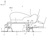
- FIG. 2 is a side view showing a seat and battery fixing structure according to an embodiment.
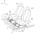
- FIG. 2 is a perspective view of the main parts inside the vehicle interior showing the fixing structure of FIG. 1.
- FIG. FIG. 2 is a plan view of main parts inside the vehicle interior showing the arrangement of batteries according to the embodiment.
- FIG. 4 is a cross-sectional view of main parts (cross-sectional view taken along the line AA in FIG. 3) showing the arrangement of the battery according to the embodiment.
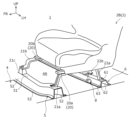
- FIG. 2 is a perspective view of essential parts of the fixing structure of FIG. 1;
- FIG. 6 is a perspective view of FIG. 5 with the battery removed.
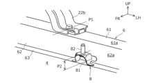
- FIG. 2 is a perspective view showing a battery fixing part and a seat fixing part of the fixing structure of FIG. 1; 8 is an enlarged view of the main part of FIG. 7.
- FIG. FIG. 2 is a perspective view showing a battery fixing part of the fixing structure of FIG. 1;
- FIG. 2 is a side view showing the effect of the fixing structure of FIG. 1
- the forward direction of the vehicle is referred to as the front (vehicle front), left and right are defined with the front as a reference, and the left and right direction of the vehicle is also referred to as the vehicle width direction.
- the side away from the vehicle body center line is defined as the outer side, and the side approaching the vehicle body center line is defined as the inner side.
- the fixing structure fixes a seat 2 and a running battery 3 in a vehicle interior 1 to a cross member 6 disposed on a floor panel 4. It is something.
- a vehicle interior 1 includes a pair of front seats 2 (a right-hand seat 2A and a left-hand seat 2B) and a rear seat (not shown). Each rear part of the battery 3 is fixed by this fixing structure.
- a cross member 5 (hereinafter also referred to as “front cross member 5”) is disposed on the floor panel 4 in the vehicle interior 1 at the front of the vehicle interior 1. ) and a cross member 6 (hereinafter also referred to as “intermediate cross member 6") disposed at an intermediate portion in the front-rear direction are fixed by welding.
- this fixing structure is a structure in which the fixing structure is fixed to the rear cross member 6 of the two cross members 5 and 6.
- a tunnel portion 11 and a dash panel 12 are provided in front of the front cross member 5 on the floor panel 4, and a pair of left and right side frames 13 are provided on the left and right edges of the floor panel 4. .
- the driving battery 3 is configured by housing a battery module 31, wiring, etc. (not shown) inside a battery case 30.
- a battery case 30 Although wiring, equipment for air conditioning the battery module 31, etc. are attached to the outside of the battery case 30, the battery case 30 is shown in a simple box shape in FIGS. 1 to 3 and the like.
- the battery case 30 includes a case body with an open top and a battery cover that covers the top opening of the case body.
- the running battery 3 is also simply referred to as "battery 3" hereinafter.
- Both the front cross member 5 and the intermediate cross member 6 have hat-shaped cross sections.
- Each cross member 5, 6 is arranged with the top wall portions 51, 61, which are hat-shaped top surface portions, facing upward, and is bent at the lower edge of the vertical wall portions 52, 62 on both edges of the top wall portions 51, 61.
- the flanges 53 and 63 thus formed are welded and fixed to the upper surface of the floor panel 4.
- the intermediate cross member 6 extends linearly in the width direction, whereas the front cross member 5 has its middle portion in the width direction at the left and right ends. In contrast, it is shifted forward so as to be separated from the intermediate cross member 6, and extends while being bent in the width direction when viewed from above.
- the fixing structures of the pair of front seats 2 are symmetrical and have substantially the same structure.
- These front seats 2 are installed on a pair of left and right seat rails 20 (that is, an outer seat rail 20a and an inner seat rail 20b) so as to be slidable in the front-rear direction.
- left and right seat rails 20 that is, an outer seat rail 20a and an inner seat rail 20b
- the present embodiment is illustrated focusing on the configuration of the left-hand seat 2B in the vehicle interior 1, the configuration of the right-hand seat 2A is also similar.
- the front part of the outer seat rail 20a is fixed to the top wall part 51 of the front cross member 5 via the front leg part 21a.
- the rear part of the outer seat rail 20a is fixed to the top wall part 61 of the intermediate cross member 6 via the rear leg part 22a.
- the front part of the inner seat rail 20b is fixed to the top wall part 51 of the front cross member 5 via the front leg part 21b and the auxiliary bracket 21c.
- the rear part of the inner seat rail 20b is fixed to the top wall part 61 of the intermediate cross member 6 via the rear leg part 22b.
- Each fixation is performed using a fastening member such as a bolt.
- the battery 3 is arranged directly below the front seat 2 between the front cross member 5 and the intermediate cross member 6. As mentioned above, since the widthwise intermediate portion of the front cross member 5 is separated from the intermediate cross member 6, there is a relatively long distance between the two cross members 5 and 6 in the longitudinal direction of the vehicle. A battery 3 can be accommodated.
- the height dimension H1 (see Fig. 1) of the space directly below the front seat 2 (the space between the front seat 2 and the floor panel 4 below it) is limited by various conditions, so this height dimension It is difficult to make H1 greater than the height H2 of the battery 3 (see FIG. 4). Therefore, in the vehicle of this embodiment, as shown in FIG. 4, a part of the floor panel 4 is made to protrude downward to ensure a space in which the battery 3 can be accommodated.
- an opening 4A (see FIGS. 4 and 6) is formed by cutting out the part of the floor panel 4 where the battery 3 is to be placed, and a battery tray that is convex downward is formed in the opening 4A (see FIGS. 4 and 6). 41 is installed.
- the battery tray 41 is liquid-tightly fixed to the floor panel 4 and closes the opening 4A. Therefore, the battery 3 mounted on the vehicle has an upper half located above the opening 4A of the floor panel 4, and a lower half located in the space within the battery tray 41 below the opening 4A of the floor panel 4.
- a pair of left and right battery fixing brackets 7 (hereinafter referred to as “second brackets 7") are coupled to the battery case 30.
- the battery 3 is fixed to each second bracket 7 by welding, bolts, etc., and the front and rear ends of each second bracket 7 are fastened and fixed to the front cross member 5 and intermediate cross member 6, respectively. It is fixed to the vehicle by being fixed to the vehicle.
- the second bracket 7 is formed, for example, by press-molding a sheet metal. As shown in FIG. 4, the second bracket 7 of this embodiment is formed into a hat shape when viewed from the side. That is, the second bracket 7 includes a band-shaped case fixing part 71 that is fixed to the upper part of the battery case 30 (for example, a battery cover) and extends in the longitudinal direction of the vehicle when the battery 3 is installed in the vehicle, and a front edge part of the case fixing part 71. It has arm parts 72, 73 bent downward from the rear edge, and fastening parts 74, 75 bent forward or backward and extending horizontally from the lower edge of each arm part 72, 73.
- the battery case 30 for example, a battery cover
- the widthwise center portions of the case fixing portion 71 and the arm portions 72, 73 are formed to protrude outward (in the direction away from the battery case 30) in a bead shape, thereby increasing strength and rigidity. Note that the bead is not essential and can be omitted.
- each second bracket 7 As shown in FIGS. 1 to 5, the front fastening portions 74 of each second bracket 7 are fastened and fixed to the top wall portion 51 of the front cross member 5 by bolts or the like.
- the rear fastening portion 75 (one end) of each second bracket 7 is connected to a cross member side bracket 8 (hereinafter referred to as "the first end") which is welded and fixed to the cross member 6. It is fastened and fixed to a bracket (referred to as "one bracket 8").
- the second bracket 7 (particularly the fastening portion 75 at the rear thereof) that fixes the rear side of the battery 3 to the cross member 6 and the first bracket 8 constitute a battery fixing portion of the battery 3 on the rear side of the vehicle. be done.
- the battery fixing part has two brackets 7 and 8, and fixes the battery 3 to the cross member 6 via these two brackets 7 and 8.
- the rear part of the outer seat rail 20a of the front seat 2 is directly fixed to the upper surface 61a of the top wall part 61 of the cross member 6 via the rear leg part 22a by fastening with bolts or the like.
- the rear portion of the seat rail 20b inside the front seat 2 is directly fixed to the upper surface 61a of the top wall portion 61 of the cross member 6 via the rear leg portion 22b by fastening with bolts or the like.
- the fixed position (height position) on the rear side of the front seat 2 in the vertical direction of the vehicle will be referred to as a first position P1 (see FIG. 1). That is, the first position P1 is provided on the upper surface 61a of the top wall portion 61 of the cross member 6.
- the first bracket 8 to which the second bracket 7 is fastened and fixed is located between the outer rear leg part 22a and the inner rear leg part 22b, as shown in FIGS. It is arranged near the rear leg portion 22a.
- the first bracket 8 of the present embodiment includes a surface 62a of the front standing wall portion 62 of the cross member 6 (vehicle front side surface of the cross member 6) and an upper surface of the front flange portion 63. (Flange surface) Welded and fixed to each of 63a.
- the fixed position (height position) on the rear side of the battery 3 in the vertical direction of the vehicle will be referred to as a second position P2 (see FIG. 1). That is, the second position P2 is lower than the first position P1, and is provided on the front side surface 62a of the cross member 6 in this embodiment.
- the second position P2 can be said to be a position where the battery fixing part (the rear fastening part 75 of the second bracket 7 and the first bracket 8) is fixed to the cross member 6, and may be lower than the first position P1. It is set on at least one of the vehicle front side side surface 62a and the flange surface 63a of the cross member 6. Note that the second position P2 is not limited to one point in the vertical direction (only at a certain height position), but may have a width in the vertical direction as shown in FIG. In the fixing structure of this embodiment, since the rear part of the battery 3 is fixed to the cross member 6 via the first bracket 8, the entire fixing range of the first bracket 8 to the cross member 6 is at the second position P2. Even with such a width, the second position P2 is still lower than the first position P1.
- the first bracket 8 includes a bracket body 81 formed by bending a sheet metal of a predetermined shape, and a bolt portion 82 that projects upward from the bracket body 81.
- the bracket main body 81 is parallel to the upper surface 63a (hereinafter referred to as "flange surface 63a") of the flange portion 63 of the cross member 6 on the vehicle front side, and in the extending direction of the cross member 6 (i.e., in the vehicle width direction). ), and two support surface parts 81b bent downward from both sides in the extending direction of the base part 81a.
- a flange-shaped first fixing part 81c is bent at the lower edge of each support surface part 81b, and a flange-shaped second fixing part 81d is bent at the side edge of each support surface part 81b on the cross member 6 side. It is formed.
- the bracket main body 81 has two flange-shaped first fixing parts 81c that are spaced apart from each other and are welded and fixed to the flange surface 63a, and a portion between and above these two first fixing parts 81c. It has a base part 81a located in parallel to the flange surface 63a, and two support surface parts 81b connecting both sides of the base part 81a and each first fixing part 81c. Furthermore, the bracket main body 81 of this embodiment has a flange-shaped second fixing part 81d that is connected to each support surface part 81b and fixed to the side surface 62a of the cross member 6 by welding.
- each first fixing part 81c is welded and fixed to the flange surface 63a of the cross member 6, and each second fixing part 81d is welded and fixed to the vehicle front side surface 62a of the cross member 6. . That is, in this embodiment, the first bracket 8 is fixed to both the vehicle front side surface 62a and the flange surface 63a of the cross member 6, and the second position P2 has a width.
- the rear fastening portion 75 of the second bracket 7 that is fastened and fixed to the first bracket 8 includes a joint surface portion 76 that is joined to the base surface portion 81a of the first bracket 8, and a joint surface portion 76 that is connected to the base surface portion 81a of the first bracket 8. It has a bolt hole 77 formed therein, and a platform portion 78 welded and fixed to an area centered on the bolt hole 77 on the upper surface of the joint surface portion 76 . Note that in FIG. 9, the bolt portion 82 is omitted for convenience.
- the platform portion 78 has three leg portions 78a, 78b, and 78c extending substantially vertically from the joint surface portion 76, and a top surface portion 78d located above the leg portions 78a to 78c.
- the platform portion 78 has a substantially rectangular box-like shape, the top surface portion 78d corresponds to the top surface of the box, and the leg portions 78a to 78c correspond to three side surfaces of the box.
- the platform portion 78 illustrated in FIG. 9 is open to the rear of the vehicle, legs constituting side surfaces may also be provided at the rear of the vehicle, and if rigidity is ensured, two opposing side surfaces may be provided. Legs (eg, legs 78a and 78c) may be provided.
- the upper surface 78e of the top surface portion 78d of the platform portion 78 is planar, and its height position is set to be the same or almost the same as the height position of the upper surface 61a of the cross member 6. . Further, the upper surface 78e and the upper surface 61a are set parallel to each other. Therefore, the rear end portion of the second bracket 7 is provided with an upper surface portion 78e of the top surface portion 78d, which is a flat surface portion that is flush with or approximately flush with the upper surface 61a of the cross member 6.
- the bolt part 82 of the first bracket 7 is inserted into the bolt hole 77 so that it protrudes above the joint surface part 76, and the protruding bolt part 82 is inserted into the bolt hole 77 as shown in the figure. Do not tighten the nuts.
- a tool insertion hole 79 is formed in the top surface portion 78d so that a fastening tool can be inserted into the internal space of the platform portion 78.
- the members related to fixing the battery 3 are It is possible to avoid protruding upward from the upper surface 61a of the member 6. Thereby, as shown in FIG. 10, it becomes easy to secure a leg space below the seat 2 for the occupant seated on the seat behind the seat 2.
- the second position P2 is set at at least one of the vehicle front side surface 62a and the flange surface 63a of the cross member 6.
- the upper surface 78e of the fastening portion 75 is provided as a flat portion that is flush or approximately flush with the upper surface 61a of the cross member 6. Therefore, as shown in FIG. 10, for example, the rear seat occupant can place his or her feet on these surfaces 61a and 78e. In other words, even if the occupant puts his or her feet under the seat 2, the occupant can do so without feeling uncomfortable.
- the dashed-dotted line in FIG. 10 shows the upper surface of the floor carpet 10 laid
- the first bracket 8 Since the two flange-shaped first fixing parts 81c of the first bracket 8 are welded and fixed to the flange surface 63a of the cross member 6, the first bracket 8 must be positioned and fixed to the cross member 6 in advance. can be assembled together. Thereby, the positioning accuracy of the first bracket 8 can be easily achieved, and the ease of assembling the battery 3 to the vehicle can be improved.
- the rigidity and strength of the first bracket 8 itself can be reduced. can be increased. Furthermore, the mounting rigidity and strength of the first bracket 8 to the cross member 6 can be increased, making it easier to ensure the rigidity and strength for fixing the battery 3.
- the above-mentioned fixing structure is an example, and is not limited to the above-mentioned one.
- the first bracket 8 is fixed to both the vehicle front side surface 62a and the flange surface 63a of the cross member 6, but if mounting rigidity and strength can be secured, the first bracket 8 can be fixed to only the flange surface 63a. It may be fixed to the side surface 62a, or it may be fixed only to the side surface 62a.
- the specific shapes of the first bracket 8 and the second bracket 7 are not limited to those of the above embodiment.
- the first bracket 8 is formed by bending a sheet metal of a predetermined shape, and has a base portion 81a and two support surface portions 81b bent downward from both sides in the extending direction of the base portion 81a.
- the number of two supporting surface portions 81b may be further increased.
- the first bracket 8 may be omitted and the rear end portion of the battery 3 may be directly fixed to the cross member 6.
- the shape of the pedestal part 78 provided on the rear fastening part 75 may not be as described above, or the pedestal part 78 may be omitted.
- the rear end portion of the second bracket 7 includes a flat portion that is flush with or substantially flush with the upper surface 61a of the cross member 6, the flat portion is not essential.
- the second bracket 7 does not have to be a pair on the left and right sides of the battery 3, and its shape is not limited to a hat shape when viewed from the side.
- the structure for mounting and fixing the battery 3 on the vehicle does not have to be a structure in which the battery module 30 is suspended as described above, or the second bracket 7 is connected to the upper part of the battery 3 and connected to the cross member 6.
- parts such as a bracket may be attached to the side or bottom of the battery 3 and fixed to the cross member 6, or a fixing part for the cross member 6 may be provided on the battery case itself without using a bracket or the like. good.
- the present fixing structure is applied to the rear end portion of the battery 3 and the portion where the rear leg portions 22a and 22b of the front seat 2 are fixed to the cross member 6.
- it may be applied to a portion where the rear end portion of the battery 3 and the rear leg portion of the second row seat are fixed to the cross member.
- the present invention can be used in the vehicle manufacturing industry where the battery and seat are fixed to the cross member. It can also be used in the manufacturing industry of vehicles with frames including cross members.
Landscapes
- Engineering & Computer Science (AREA)
- Transportation (AREA)
- Mechanical Engineering (AREA)
- Chemical & Material Sciences (AREA)
- Combustion & Propulsion (AREA)
- Aviation & Aerospace Engineering (AREA)
- Body Structure For Vehicles (AREA)
- Seats For Vehicles (AREA)
- Arrangement Or Mounting Of Propulsion Units For Vehicles (AREA)
Priority Applications (2)
| Application Number | Priority Date | Filing Date | Title |
|---|---|---|---|
| PCT/JP2022/009742 WO2023170745A1 (ja) | 2022-03-07 | 2022-03-07 | シート及びバッテリの固定構造 |
| JP2022556104A JP7243935B1 (ja) | 2022-03-07 | 2022-03-07 | シート及びバッテリの固定構造 |
Applications Claiming Priority (1)
| Application Number | Priority Date | Filing Date | Title |
|---|---|---|---|
| PCT/JP2022/009742 WO2023170745A1 (ja) | 2022-03-07 | 2022-03-07 | シート及びバッテリの固定構造 |
Publications (1)
| Publication Number | Publication Date |
|---|---|
| WO2023170745A1 true WO2023170745A1 (ja) | 2023-09-14 |
Family
ID=85685013
Family Applications (1)
| Application Number | Title | Priority Date | Filing Date |
|---|---|---|---|
| PCT/JP2022/009742 Ceased WO2023170745A1 (ja) | 2022-03-07 | 2022-03-07 | シート及びバッテリの固定構造 |
Country Status (2)
| Country | Link |
|---|---|
| JP (1) | JP7243935B1 (https=) |
| WO (1) | WO2023170745A1 (https=) |
Cited By (1)
| Publication number | Priority date | Publication date | Assignee | Title |
|---|---|---|---|---|
| CN117360237A (zh) * | 2023-11-24 | 2024-01-09 | 浙江天成自控股份有限公司 | 一种保护后排电池包的结构 |
Families Citing this family (1)
| Publication number | Priority date | Publication date | Assignee | Title |
|---|---|---|---|---|
| JP7720346B2 (ja) * | 2023-03-31 | 2025-08-07 | ダイハツ工業株式会社 | 電動車 |
Citations (5)
| Publication number | Priority date | Publication date | Assignee | Title |
|---|---|---|---|---|
| JP2020138567A (ja) * | 2019-02-26 | 2020-09-03 | トヨタ自動車株式会社 | 車両下部構造 |
| US20200282818A1 (en) * | 2019-03-06 | 2020-09-10 | Ford Global Technologies, Llc | Vehicle battery and seat assembly |
| JP2020199897A (ja) * | 2019-06-11 | 2020-12-17 | ダイハツ工業株式会社 | 車両構造 |
| JP2021017095A (ja) * | 2019-07-18 | 2021-02-15 | トヨタ自動車株式会社 | バッテリ搭載構造 |
| JP2021030918A (ja) * | 2019-08-26 | 2021-03-01 | 本田技研工業株式会社 | 車体下部構造 |
-
2022
- 2022-03-07 JP JP2022556104A patent/JP7243935B1/ja active Active
- 2022-03-07 WO PCT/JP2022/009742 patent/WO2023170745A1/ja not_active Ceased
Patent Citations (5)
| Publication number | Priority date | Publication date | Assignee | Title |
|---|---|---|---|---|
| JP2020138567A (ja) * | 2019-02-26 | 2020-09-03 | トヨタ自動車株式会社 | 車両下部構造 |
| US20200282818A1 (en) * | 2019-03-06 | 2020-09-10 | Ford Global Technologies, Llc | Vehicle battery and seat assembly |
| JP2020199897A (ja) * | 2019-06-11 | 2020-12-17 | ダイハツ工業株式会社 | 車両構造 |
| JP2021017095A (ja) * | 2019-07-18 | 2021-02-15 | トヨタ自動車株式会社 | バッテリ搭載構造 |
| JP2021030918A (ja) * | 2019-08-26 | 2021-03-01 | 本田技研工業株式会社 | 車体下部構造 |
Cited By (1)
| Publication number | Priority date | Publication date | Assignee | Title |
|---|---|---|---|---|
| CN117360237A (zh) * | 2023-11-24 | 2024-01-09 | 浙江天成自控股份有限公司 | 一种保护后排电池包的结构 |
Also Published As
| Publication number | Publication date |
|---|---|
| JP7243935B1 (ja) | 2023-03-22 |
| JPWO2023170745A1 (https=) | 2023-09-14 |
Similar Documents
| Publication | Publication Date | Title |
|---|---|---|
| US11420686B2 (en) | Lower vehicle-body structure of electric vehicle | |
| US11220298B2 (en) | Lower vehicle-body structure of electric vehicle | |
| US9487236B2 (en) | Vehicle body front section structure | |
| KR101800392B1 (ko) | 승객 좌석을 고정하는 돌출 박스 구조를 구비한 섀시 | |
| CN104553717B (zh) | 电动车辆 | |
| CN210364088U (zh) | 一种电动汽车前地板总成 | |
| EP3738865B1 (en) | Lower vehicle-body structure of a vehicle, vehicle-body structure of a vehicle, and vehicle | |
| JP6517859B2 (ja) | 車体フロア構造 | |
| JP5525562B2 (ja) | 自動車のフロア構造 | |
| JP7243935B1 (ja) | シート及びバッテリの固定構造 | |
| JP2023002335A (ja) | 運転席周辺構造 | |
| CN113212562A (zh) | 车辆的地板构造 | |
| JP2014019260A (ja) | 電池パックの位置決めピンブラケット | |
| JP2019059478A (ja) | 車両用バッテリパックの取付け構造 | |
| JP2020185906A (ja) | 電動車両の下部車体構造 | |
| JP7338231B2 (ja) | 電動車両の下部車体構造 | |
| JP7563623B2 (ja) | 電動車両 | |
| JP7613611B2 (ja) | 電気機器の取付構造 | |
| JP2008110634A (ja) | 車両の下部車体構造 | |
| JP2023114178A (ja) | 電動車両の電線配索構造 | |
| JP3863049B2 (ja) | シートの取付構造 | |
| JP2601563Y2 (ja) | 自動車の側部車体構造 | |
| CN210122135U (zh) | 车辆下部结构 | |
| JP7468434B2 (ja) | 車体構造 | |
| JP2025147995A (ja) | 車両の下部車体構造 |
Legal Events
| Date | Code | Title | Description |
|---|---|---|---|
| WWE | Wipo information: entry into national phase |
Ref document number: 2022556104 Country of ref document: JP |
|
| 121 | Ep: the epo has been informed by wipo that ep was designated in this application |
Ref document number: 22930731 Country of ref document: EP Kind code of ref document: A1 |
|
| NENP | Non-entry into the national phase |
Ref country code: DE |
|
| 122 | Ep: pct application non-entry in european phase |
Ref document number: 22930731 Country of ref document: EP Kind code of ref document: A1 |