WO2023140233A1 - ステータコイルの製造方法、回転電機の製造方法、ステータ、および回転電機 - Google Patents
ステータコイルの製造方法、回転電機の製造方法、ステータ、および回転電機 Download PDFInfo
- Publication number
- WO2023140233A1 WO2023140233A1 PCT/JP2023/001114 JP2023001114W WO2023140233A1 WO 2023140233 A1 WO2023140233 A1 WO 2023140233A1 JP 2023001114 W JP2023001114 W JP 2023001114W WO 2023140233 A1 WO2023140233 A1 WO 2023140233A1
- Authority
- WO
- WIPO (PCT)
- Prior art keywords
- coil
- coils
- winding
- core
- stator
- Prior art date
- Legal status (The legal status is an assumption and is not a legal conclusion. Google has not performed a legal analysis and makes no representation as to the accuracy of the status listed.)
- Ceased
Links
Images













Classifications
-
- H—ELECTRICITY
- H02—GENERATION; CONVERSION OR DISTRIBUTION OF ELECTRIC POWER
- H02K—DYNAMO-ELECTRIC MACHINES
- H02K3/00—Details of windings
- H02K3/04—Windings characterised by the conductor shape, form or construction, e.g. with bar conductors
- H02K3/28—Layout of windings or of connections between windings
-
- B—PERFORMING OPERATIONS; TRANSPORTING
- B21—MECHANICAL METAL-WORKING WITHOUT ESSENTIALLY REMOVING MATERIAL; PUNCHING METAL
- B21F—WORKING OR PROCESSING OF METAL WIRE
- B21F3/00—Coiling wire into particular forms
- B21F3/02—Coiling wire into particular forms helically
-
- H—ELECTRICITY
- H02—GENERATION; CONVERSION OR DISTRIBUTION OF ELECTRIC POWER
- H02K—DYNAMO-ELECTRIC MACHINES
- H02K15/00—Processes or apparatus specially adapted for manufacturing, assembling, maintaining or repairing of dynamo-electric machines
- H02K15/04—Processes or apparatus specially adapted for manufacturing, assembling, maintaining or repairing of dynamo-electric machines of windings prior to their mounting into the machines
- H02K15/0414—Processes or apparatus specially adapted for manufacturing, assembling, maintaining or repairing of dynamo-electric machines of windings prior to their mounting into the machines the windings consisting of separate elements, e.g. bars, segments or half coils
- H02K15/0421—Processes or apparatus specially adapted for manufacturing, assembling, maintaining or repairing of dynamo-electric machines of windings prior to their mounting into the machines the windings consisting of separate elements, e.g. bars, segments or half coils and consisting of single conductors, e.g. hairpins
- H02K15/0428—Processes or apparatus for simultaneously twisting two or more hairpins
-
- H—ELECTRICITY
- H02—GENERATION; CONVERSION OR DISTRIBUTION OF ELECTRIC POWER
- H02K—DYNAMO-ELECTRIC MACHINES
- H02K15/00—Processes or apparatus specially adapted for manufacturing, assembling, maintaining or repairing of dynamo-electric machines
- H02K15/04—Processes or apparatus specially adapted for manufacturing, assembling, maintaining or repairing of dynamo-electric machines of windings prior to their mounting into the machines
- H02K15/043—Processes or apparatus specially adapted for manufacturing, assembling, maintaining or repairing of dynamo-electric machines of windings prior to their mounting into the machines winding flat conductive wires or sheets
- H02K15/0431—Concentrated windings
-
- H—ELECTRICITY
- H02—GENERATION; CONVERSION OR DISTRIBUTION OF ELECTRIC POWER
- H02K—DYNAMO-ELECTRIC MACHINES
- H02K15/00—Processes or apparatus specially adapted for manufacturing, assembling, maintaining or repairing of dynamo-electric machines
- H02K15/04—Processes or apparatus specially adapted for manufacturing, assembling, maintaining or repairing of dynamo-electric machines of windings prior to their mounting into the machines
- H02K15/043—Processes or apparatus specially adapted for manufacturing, assembling, maintaining or repairing of dynamo-electric machines of windings prior to their mounting into the machines winding flat conductive wires or sheets
- H02K15/0432—Distributed windings
-
- H—ELECTRICITY
- H02—GENERATION; CONVERSION OR DISTRIBUTION OF ELECTRIC POWER
- H02K—DYNAMO-ELECTRIC MACHINES
- H02K15/00—Processes or apparatus specially adapted for manufacturing, assembling, maintaining or repairing of dynamo-electric machines
- H02K15/06—Embedding prefabricated windings in the machines
-
- H—ELECTRICITY
- H02—GENERATION; CONVERSION OR DISTRIBUTION OF ELECTRIC POWER
- H02K—DYNAMO-ELECTRIC MACHINES
- H02K15/00—Processes or apparatus specially adapted for manufacturing, assembling, maintaining or repairing of dynamo-electric machines
- H02K15/06—Embedding prefabricated windings in the machines
- H02K15/062—Windings in slots; Salient pole windings
- H02K15/065—Windings consisting of complete sections, e.g. coils or waves
- H02K15/066—Windings consisting of complete sections, e.g. coils or waves inserted perpendicularly to the axis of the slots or inter-polar channels
-
- H—ELECTRICITY
- H02—GENERATION; CONVERSION OR DISTRIBUTION OF ELECTRIC POWER
- H02K—DYNAMO-ELECTRIC MACHINES
- H02K15/00—Processes or apparatus specially adapted for manufacturing, assembling, maintaining or repairing of dynamo-electric machines
- H02K15/08—Forming windings by laying conductors into or around core parts
- H02K15/085—Forming windings by laying conductors into or around core parts by laying conductors into slotted stators
-
- Y—GENERAL TAGGING OF NEW TECHNOLOGICAL DEVELOPMENTS; GENERAL TAGGING OF CROSS-SECTIONAL TECHNOLOGIES SPANNING OVER SEVERAL SECTIONS OF THE IPC; TECHNICAL SUBJECTS COVERED BY FORMER USPC CROSS-REFERENCE ART COLLECTIONS [XRACs] AND DIGESTS
- Y02—TECHNOLOGIES OR APPLICATIONS FOR MITIGATION OR ADAPTATION AGAINST CLIMATE CHANGE
- Y02T—CLIMATE CHANGE MITIGATION TECHNOLOGIES RELATED TO TRANSPORTATION
- Y02T10/00—Road transport of goods or passengers
- Y02T10/60—Other road transportation technologies with climate change mitigation effect
- Y02T10/64—Electric machine technologies in electromobility
Definitions
- This application relates to a stator coil manufacturing method, a rotating electric machine manufacturing method, a stator, and a rotating electric machine.
- the conductors are not arranged and wound in a regular manner, the conductors cross each other in the straight part of the coil, and the dimensions may be swollen.
- the coils are pushed into the core slots while the alignment is broken, the coils will become entangled in the core slots and the coils will bend and swell. As a result, the proportion of coils in the core slots is lower than in the aligned state (the number of coils that can be placed in the core slots is reduced), which poses a problem of not improving the motor performance.
- the present application was made to solve the above-mentioned problems, and aims to provide a method of manufacturing a stator coil that achieves high quality and high productivity.
- the method for manufacturing a stator coil disclosed in the present application includes: A stator coil manufacturing method comprising winding a plurality of conductor wires around a winding frame to form a coil, and inserting the formed coil into a slot of a stator core, A winding step of arranging a plurality of conductor wires in a row, winding them a predetermined number of times on each of a plurality of winding frames having different diameters while maintaining the aligned state, and forming a plurality of coils connected by connecting wires; A gripping step of removing each of the plurality of coils from the winding frame while maintaining the aligned state of the plurality of conductors; and an inserting step of stacking and arranging the plurality of gripped coils in the stator core in the order of inserting them into the slots, and then inserting the coils into the slots.
- the work of inserting a plurality of coils connected by crossover wires can be easily performed, and since the coils can be easily inserted into the slots of the stator core, it is possible to manufacture a high quality and highly productive stator core without damaging the coil insulating coating.
- FIG. 1 is an external view of a stator according to Embodiment 1, where (a) is a perspective view of a stator core, (b) is a perspective view of a stator core assembled with a rotor, and (c) is a cross-sectional perspective view of (b).
- FIG. 4 is a diagram illustrating a winding device for manufacturing three continuous coils to be incorporated into the stator core according to Embodiment 1;
- FIG. 3 is a schematic diagram illustrating the positional relationship of each configuration when FIG. 2 is viewed from the right side of the paper surface; 4 is a front view of a winding section having a dedicated winding frame according to Embodiment 1.
- FIG. 2 is a side view of the dedicated winding frame according to Embodiment 1; BRIEF DESCRIPTION OF THE DRAWINGS It is a figure explaining the strain relief device which concerns on Embodiment 1, (a) is a perspective view, (b) is sectional drawing. 4 is a diagram showing a state in which a coil is wound around the bobbin according to the first embodiment; FIG. FIG.
- FIG. 10 is a front view of the winding unit showing a winding end state
- 1 is a diagram showing a state in which a dedicated winding frame of Embodiment 1 is removed from a winding unit
- (a) is a front view
- (b) is a side view
- (c) is a diagram showing a state in which three continuous coils are connected by a connecting wire. It is a figure explaining the re-gripping process which concerns on Embodiment 1, (a) is a front view, (b) is the figure which looked at (a) from the paper surface right side.
- FIG. 8 is a diagram showing a state in which the coil is gripped by the coil chuck in the re-gripping process according to the first embodiment;
- FIG. 10 is a diagram showing the coil chuck with the coil gripped attached to the chuck fixing jig in the insertion step according to the first embodiment
- FIG. 8 is a diagram illustrating a state in which the coil chucks holding the coil are stacked in two stages in the insertion step according to the first embodiment
- FIG. 7 is a diagram illustrating a state in which coil chucks holding coils are stacked in three stages in the insertion step according to the first embodiment
- FIG. 7 is a diagram illustrating a state in which the coil chucks holding the coil are stacked in three stages and inserted into the stator core in the insertion step according to the first embodiment
- FIG. 16 is a view showing the relationship between the coil, coil chuck, and fixture as viewed from view A in FIG.
- FIG. 4 is a diagram for explaining an insertion process according to Embodiment 1, in which (a) is when a small coil is inserted in the first stage, (b) is when a large coil is inserted in a second stage, and (c) is when a small coil is inserted in a third stage. It is a figure explaining the process which inserts a coil in a core slot with a coil pusher. (a) indicates the start of insertion, (b) indicates the middle of insertion, and (c) indicates the completion of insertion.
- FIG. 4 is a diagram for explaining a state when a coil is inserted and a relationship between a coil chuck width dimension and a core slot opening dimension; FIG.
- FIG. 10 is a diagram illustrating a winding device for manufacturing three continuous coils to be incorporated into a stator core according to Embodiment 2;
- FIG. 10 is a cross-sectional view of a state in which a lead wire is inserted into the strain relief according to the second embodiment;
- FIG. 10 is a diagram illustrating a state in which winding of a specified number of times on a winding frame for small coils of a winding device for manufacturing three continuous coils to be incorporated into a stator core according to Embodiment 2 is completed;
- FIG. 10 is a diagram for explaining the state of conductors inserted into the strain relief according to the second embodiment; (a) shows the state before the wire replacement, and (b) and (c) show the state after the wire replacement.
- FIG. 10 is a diagram illustrating a winding device for manufacturing three continuous coils to be incorporated into a stator core according to Embodiment 2;
- FIG. 10 is a cross-sectional view of a state
- FIG. 10 is a diagram for explaining a state of a winding device for manufacturing three continuous coils to be incorporated into a stator core according to Embodiment 2 after the conductors are replaced;
- FIG. 10 is a diagram for explaining the state of conductors inserted into the strain relief according to the second embodiment; (a) shows the state before the wire replacement, and (b) and (c) show the state after the wire replacement.
- FIG. 10 is a diagram for explaining the arrangement order of three continuous coils to be incorporated into the stator core according to Embodiment 2;
- FIG. 10 is a diagram for explaining the arrangement order of three continuous coils to be incorporated into the stator core according to Embodiment 2;
- FIG. 10 is a diagram for explaining the arrangement order of three continuous coils to be incorporated into the stator core according to Embodiment 2;
- FIG. 7 is a diagram illustrating the order of arrangement of conductors in core slots of a stator core according to Embodiment 2; (a), (b), and (c) show the state in which the order of the conductors inserted into the core slots in each coil is reversed.
- FIG. 10 is a diagram for explaining the arrangement order of three continuous coils to be incorporated into the stator core according to Embodiment 2;
- FIG. 10 is a diagram illustrating a state of a connecting wire of conductors in a core slot of a stator core according to Embodiment 2;
- FIG. 11 is a diagram illustrating attachment of a coil chuck for a coil inserted into a stator core according to Embodiment 3; (a) shows the third coil, (b) shows the second coil, and (c) shows the first coil.
- FIG. 10 is a diagram illustrating the order of arrangement of conductors in core slots of a stator core according to Embodiment 3; (a) shows the third coil, (b) shows the second coil, and (c) shows the first coil.
- FIG. 10 is a diagram illustrating a state of a connecting wire of conductors in a core slot of a stator core according to Embodiment 3;
- stator coil manufacturing method A preferred embodiment of the stator coil manufacturing method according to the present application will be described below with reference to the drawings.
- the same reference numerals are assigned to the same contents and corresponding parts, and detailed description thereof will be omitted.
- FIG. 1(a) is a perspective view showing the appearance of a stator core 2 of a stator manufactured according to this embodiment and the shape of a coil 5 inserted into the stator core 2.
- FIG. 1A shows a stator core 2 of a 3-layer, 4-pole, 36-slot electric motor, in which coils 5 formed by concentric lap winding of distributed winding are accommodated in core slots 3 .
- FIG. 1(b) is a perspective view showing a state in which the rotor 4 is incorporated into the stator core 2.
- FIG. The rotor 4 is used in a three-phase induction motor, and has a rotor core in which iron cores are laminated in the axial direction, and a conductor (not shown) through which an induced current flows. Also, the rotor 4 may be used for a three-phase synchronous motor in which magnets are arranged in the rotor core.
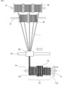
- FIGS. 2 and 3 show a winding device for manufacturing three continuous coils to be incorporated into the stator core 2.
- FIG. 2 is a front view
- FIG. 3 is a schematic diagram showing the positional relationship of each configuration viewed from the right side of FIG.
- the five conductor wires 1 supplied from the wire rod drum 20 are inserted into the strain relief device 30 to form a bundle aligned in a horizontal row, and then wound around the special winding frame 10 so as to form three continuous coils (three continuous coils). That is, a winding frame 11a for a small coil, a winding frame 12 for a large coil, and a winding frame 11b for a small coil are connected to a rotating shaft 14 in a skewered manner to form a dedicated winding frame 10.
- a bundle of five conductor wires 1 having a circular cross-sectional shape is continuously wound a specified number of times in the order of the winding frame 11a, the winding frame 12, and the winding frame 11b.
- the winding frames 11a, 11b, and 12 are separable by removing the rotary shaft 14. As shown in FIG.
- FIG. 4 is a front view of a winding section having a dedicated winding frame 10
- FIG. 5 is a side view of the dedicated winding frame 10.
- the dedicated winding frame 10 is dedicated to three continuous coils, but it is not limited to this.
- the winding frames 11a, 11b, and 12 are centered on the rotating shaft 14, and along the R portion of the conductor winding portion 15 having a semi-oval shape on both sides, a bundle of five conductor wires 1 is driven in a plurality of positions in the axial direction and the rotating direction of the rotating shaft 14 so that the bundle can be wound in parallel in the axial direction of the rotating shaft 14.
- the linear slide mechanism 17 connecting the opposing wire winding portions 15 has no member for restricting the wire 1, and the wire 1 can be wound straight without looseness by the tension (optimum tension) applied to the wire 1.
- the slide mechanism 17 is configured to extend and contract in the direction of the arrow in FIG. 5 so that the coil 5 can be easily removed after winding in the direction of the arrow in FIG.
- FIGS. 2 and 3 the five wire drums 20 are passed through the shafts 21, and the wires 1 are set so that they can be taken out from each of the wire drums 20.
- FIG. (2) By setting the dedicated winding frame 10 on the rotating shaft 14 and rotating the rotating handle 13 provided at the end of the rotating shaft, the dedicated winding frame 10 rotates in the direction of the arrow in FIG. At this time, as shown in FIG. 2, winding is started from the right end of the winding frame 11a for the small coil, and the five conductor wires 1 are wound in parallel between the regulating pins 16 without winding disorder.
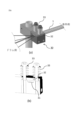
- the conductor wires 1 pulled out from each wire drum 20 at the same time are passed through a strain relief device 30 shown in FIG.
- grooves 31 corresponding to the number of conductor wires 1 to be wound are formed in parallel inside the strain relief device 30. By passing through these grooves 31, the bending of the conductor wire 1 is corrected, and the conductor wire 1 is aligned with the pitch at which the conductor wire 1 is wound around the special winding frame 10.
- a holding lid 32 is provided as shown in FIG.
- the pressing lid 32 has a structure in which the pressing force can be adjusted by a spring 33, and can apply optimum tension to the wire 1 so as not to cause loosening of the wire when the wire 1 is wound around the dedicated winding frame 10.
- the conductor wire 1 moves to the position where the winding frame 12 for the large coil is wound, and the conductor wire 1 is wound in the same manner as described above without cutting the conductor wire 1.
- the strain relief device 30 is provided with a moving means 35 so that the wire 1 is always perpendicular to the exclusive winding frame 10 and the wire is wound while sliding in the direction of the rotating shaft 14 so as not to bend the wire 1.
- - ⁇ FIG. 8 shows the moved position of the strain relief device 30 at the winding end. At this point, the wire 1 is wound around the bobbin 11a, 11b, 12 to form three consecutive coils 5. As shown in FIG.
- FIGS. 9(a) and 9(b) show a front view of the removed winding frame
- FIG. 9(b) shows a side view
- FIG. 9(c) shows a state in which the three continuous coils 5 wound around the winding frames 11a, 12, and 11b removed from the rotary shaft 14 are connected by a connecting wire 6c.
- the three continuous coils 5 are composed of a small coil 6a wound around the winding frame 11a, a large coil 7 wound around the winding frame 12, and a small coil 6b wound around the winding frame 11b, which are connected by a connecting wire 6c.
- FIG. 10(a) is a front view
- FIG. 10(b) is a view of FIG. 10(a) viewed from the right side of the paper surface.
- the coil chuck 40 is inserted between the small coil 6 a and the winding frame 11 a in the direction of the arrow, and the linear portion of the small coil 6 a is inserted into the coil chuck width 45 of the coil chuck 40 .
- the coil chuck width 45 is set narrower than the core slot opening width 44 so that the small coil 6a can be easily inserted into the core slot 3 (see FIG. 19 described later).
- the same operation is repeated in the order of the small coil 6a wound around the winding frame 11a, the large coil 7 wound around the winding frame 12, and the small coil 6b wound around the winding frame 11b, and three consecutive coils are removed from the special winding frame 10.
- Currents of the same phase among the three phases flow through the small coil 6a, the large coil 7, and the small coil 6b.
- the coil pitch which is the circumferential width between the straight portions of the small coils 6 a and 6 b that enter the slots, is smaller than the coil pitch of the large coil 7 .
- the coil pitch of the small coils 6a and 6b is a 7-slot pitch
- the coil pitch of the large coil 7 is a 9-slot pitch.
- FIG. 11 is a diagram showing a state in which, for example, the small coil 6a is gripped by the coil chuck 40 by the re-gripping process described above.
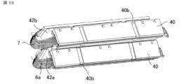
- the coil chuck 40 is mounted on a fixing jig 42a for chucking.
- the coil chuck 40 has a dovetail groove (female dovetail shape 40b on the front surface of the paper and male dovetail shape 40c on the back side of the paper surface), and is positioned and fixed by fitting the female dovetail shape 40b and the male dovetail shape 40c.
- the small coil 6a, the large coil 7, and the small coil 6b, which are held by the coil chuck 40, are radially stacked in the stator core 2 from the side closer to the core slot 3, and the small coil 6a, the large coil 7, and the small coil 6b can be held in the stator core 2 without interfering with their insertion into the core slot 3.
- the coil pitch of the small coils 6a and 6b is a 7-slot pitch
- the coil pitch of the large coil 7 is a 9-slot pitch. Therefore, when the coil chuck 40 is attached to both sides of the fixing jig 42a and set in the core slot 3 via the positioning projections 42c, it is set at a position exactly 7 slot pitches apart, as shown in FIG. Similarly, when the coil chucks 40 are attached to both sides of the positioning fixing jig 42b and set in the core slot 3 via the positioning projections 42c, they are positioned 9 slot pitches apart.
- FIG. 16 is a diagram showing a state in which the small coil 6a and the large coil 7 are viewed from direction A in FIG. 15 (the stator core 2 is omitted).
- FIG. 17 shows how each coil is inserted in chronological order.
- FIG. 17(a) is a diagram showing a state in which three-tiered coil chucks are inserted into the stator core before the coils are attached, and shows the same state as in FIG. As shown in FIG. 17( a ), the coils are radially stacked in the stator core 2 in order of insertion into the core slots 3 .
- the jig fixing spacer 43 is removed, and the insertion position of the large coil 7 is determined by fitting the positioning protrusion 42c provided on the fixing jig 42b into the slot.
- the large coil 7 is inserted into the slot next to the small coil 6a, and one straight portion of the small coil 6b is inserted into the eighth slot from the slot into which one straight portion of the large coil 7 is inserted.
- the other linear portion of the small coil 6b is inserted into the slot adjacent to the slot into which the one linear portion of the large coil 7 is inserted.
- the small coil 6a and the large coil 7 have the same winding direction, and the small coil 6b has a winding direction opposite to that of the small coil 6a and the large coil 7.
- the directions of the magnetic fields generated in the small coil 6a and the large coil 7, which are wound in the same direction are the same, being either radially inner or radially outer.
- the above operation is repeated 12 times to complete the insertion of the stator coils.
- the method of inserting the small coil 6a into the core slot 3 is as shown in FIGS. 18(a), (b), and (c).
- FIGS. 18(a), (b), and (c) when a plate-shaped coil pusher 50 with a tapered tip and a thickness thinner than the core slot opening width 44 is inserted into the gap of the coil chuck width 45 (see FIG. 10(b)) and slid in the axial direction of the stator core 2 (in the direction of the arrow in the figure), the tapered portion of the tip pushes the small coil 6a between the coil chuck 40 and the core slot 3.
- the small coil 6a can be completely inserted into the core slot 3 without bending by moving the coil pusher 50 over the entire length of the stator core 2 in the axial direction. Therefore, a stator with a higher space factor can be manufactured, and this stator can be used for manufacturing a small-sized high-output motor.
- the relationship between the coil chuck width 45 and the core slot opening width 44 is shown in FIG. As described above, the coil chuck width 45 is set narrower than the core slot opening width 44 so that the small coil 6 a can be easily inserted into the core slot 3 .
- the conductors are wound on the winding frame without being aligned, and after the winding is completed, the winding frame is dismantled and the coil is taken out. Since the coil is not wound regularly, the conductor wires cross each other in the straight part of the coil, and the dimension is swollen compared to the regular winding. Therefore, immediately before insertion into the core slot, it is necessary for the operator to disassemble the coil bundle and insert several coils into the slot so that the width of the coil bundle becomes narrower than the opening width of the slot. After the insertion, the coil is arranged again, and the coil is inserted while performing molding so that adjacent coil end portions do not overlap. As described above, the insertion process is a task requiring specialized skills, and there is also the problem that the number of operators is limited.
- stator coil manufacturing method of the present embodiment all the processes are regulated by jigs, so it is possible to manufacture stators of the same quality without relying on the skill of workers and without the conductors coming apart.
- the coils 6a, 7, 6b are inserted into the core slots 3 of the stator, the coils are aligned with a dimension narrower than the slot opening width, so that the coils can be easily inserted into the core slots 3, and the insulation coating of the conductor is not damaged such as scratches, leading to prevention of deterioration of insulation quality.
- the coils in the core slots 3 can be arranged without bending, so that a stator with a higher space factor can be manufactured.
- the conductor may have a rectangular cross-section.
- Embodiment 2 a method of manufacturing a stator coil and a structure of a stator according to Embodiment 2 will be described with reference to the drawings, with respect to portions different from those of Embodiment 1.
- FIG. 1 a coil is formed by winding each conductive wire in an aligned manner, and the coil is inserted into the core slot 3 while maintaining the alignment. Therefore, the inductance of each conductor wire may differ depending on the difference in the length of each conductor wire due to the difference in winding position, or when the position of each conductor wire in the core slot 3 is the same between the coils, depending on the magnetic saturation distribution in the adjacent teeth forming the core slot 3 when the motor is driven.
- the second embodiment aims at suppressing the decrease in efficiency of the motor by suppressing the generation of such a circulating current.
- the stator coil manufacturing method and the stator structure will be described for each process, but the ⁇ re-gripping process> and the ⁇ insertion process> are the same as in the first embodiment, so the description will be omitted.
- ⁇ Winding process> (1) First, as shown in FIG. 20, the shaft 21 is passed through the six wire drums 20A to 20F, and the wires A to F are set so that they can be taken out from the respective wire drums 20A to 20F. Although the number of conducting wires is five in the first embodiment, the number of conducting wires is six in the second embodiment for simplification of explanation.
- the dedicated winding frame 10 By setting the dedicated winding frame 10 on the rotating shaft 14 and rotating the rotating handle 13 provided at the end of the rotating shaft, the dedicated winding frame 10 is rotated to wind the wires A to F. At this time, as shown in FIG. 20, the winding is started from the right end of the winding frame 11a for the small coil, and the six conductor wires A to F are wound in parallel between the regulation pins 16 without winding disorder. As in the first embodiment, the first coil wound on the small coil winding frame 11a is wound a specified number of times around the winding frame to form the small coil 6a.
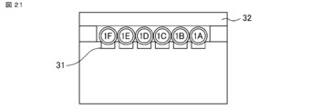
- Conducting wires A to F simultaneously pulled out from each of the wire drums 20A to 20F are passed through a distortion remover 30 shown in FIG. In FIG. 21, 1A to 1F indicate the first turn windings of the conductor wire from the wire rod drums 20A to 20F.
- grooves 31 corresponding to the number of conductors A to F to be wound are formed in parallel inside the strain relief device 30.
- the bending of the conductors A to F is corrected, and the conductors A to F are aligned to the pitch at which they are wound around the dedicated winding frame 10.
- a holding lid 32 is provided to prevent the wires A to F from coming off the grooves 31 .
- the pressing lid 32 has a structure in which the pressing force can be adjusted by the spring 33 as described in FIG.
- FIG. 22 shows the arrangement order of the conductors before and after replacement.
- FIG. 23(a) is a diagram before the replacement
- FIGS. 23(b) and 23(c) are diagrams after the replacement. At the time of replacement, it is desirable to replace the conductors within the block as shown in FIG. 23(c), but it is not necessary to replace within the block as shown in FIG.
- the top and bottom surfaces of each conductor remain the same before and after the replacement. That is, in the cross section of the connecting wire portion, the arrangement order of the lines in one direction is changed, but the arrangement order in the other direction perpendicular to the one direction is not changed.
- FIG. 24 shows the state after the conductors have been replaced.
- the conductor wire 1 is rearranged before being wound on the winding frame 12 for the second large coil. Subsequently, the conductor wire 1 is moved to a position where the winding frame 12 for the large coil is wound, and the conductor wires A to F are wound in the same manner as described above without being cut.
- the strain relief device 30 is provided with a moving means 35 so that the conductors A to F are always perpendicular to the exclusive winding frame 10, and the conductors A to F are slid in the direction of the rotating shaft 14 so as not to be bent.
- the subsequent step of winding the large coil is the same as in the first embodiment, but the arrangement order of the conducting wires is changed, so that a coil is formed in which the conducting wires are rearranged.
- FIG. 25 shows before and after replacement. As shown in FIG. 25(b), the conductors within the block may not be exchanged, or as shown in FIG. 25(c), the conductors within the block may be exchanged. After the conductor wires A to F are replaced, the conductor wire 1 is moved to a position where the winding frame 11b for the small coil, which is the third winding frame, is wound, and the conductor wire 1 is wound without cutting the conductor wires A to F.
- the structure is such that the arrangement order in one direction is changed in the crossover between the large coil 7 as the second coil and the small coil 6b as the third coil, and the order in the other direction perpendicular to the one direction is not changed.
- the third small coil 6b is wound.
- the conductors A to F are rearranged in order, forming a coil in which the conductors are rearranged.
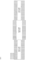
- FIG. 26 shows the arrangement order of three consecutive coils after winding in the first embodiment
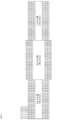
- FIG. 27 shows the arrangement order of three consecutive coils after winding in the second embodiment.
- 1A to 1F indicate the first winding of the conductor wire from the wire drums 20A to 20F
- 2A to 2F indicate the second winding of the conductor wire from the wire drums 20A to 20F. The same applies hereinafter.
- the winding order of the first coil (the coil wound around the winding frame 11a for the small coil), the second coil (the coil wound around the winding frame 12 for the large coil), and the third coil (the coil wound around the winding frame 11b for the small coil) from the right side of the paper is a repetition of A, B, C, D, E, and F.
- FIG. repeats C, D, E, F, A, and B, and the third coil repeats E, F, A, B, C, and D.
- the order of arrangement of the conductors in the core slots 3 of the coils in Embodiment 1 is the same order of the conductors as in FIG. 28A in all the core slots 3 .
- a rectangular wire having a rectangular cross-sectional shape is described as an image, but a round wire may also be used.
- the drawing shows that the conductors are wound in alignment even after the coil is inserted into the core slot 3, there is no problem even if the alignment is lost after insertion.
- the position of the strain relief device 30 is moved and the coil is wound again a plurality of times.
- the position of the strain relief device 30 may be changed for each winding.
- the conductor wire is arranged from the side closer to the winding frame, and the conductor wire wound later is arranged on the side farther from the winding frame.
- the winding direction of each coil may be changed as necessary.
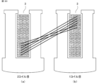
- FIG. 30 is a schematic diagram showing a connecting wire between the first coil shown in FIG. 28(c) and the second coil shown in FIG. 28(b).
- FIG. 23(b) after winding the first small coil, the arrangement order of the conductors is changed, and then the second large coil is wound.
- the conductor wires are exchanged and wound as shown in FIG. 23(b)
- the arrangement order of X/N conductor wires in one direction is exchanged between the coils in the crossover portion, and the arrangement order in the other direction orthogonal to the one direction is not exchanged.
- Embodiment 3 A method of manufacturing a stator coil and a structure of a stator according to the third embodiment will be described below, focusing on the differences from the first embodiment.
- the variation in the length of each conductor and the variation in the magnetic saturation distribution applied to each conductor during motor driving are reduced. This reduces variations in inductance and reduces circulating current.
- the number of man-hours may slightly increase because the work of replacing the conductor wires between the coils occurs.
- Embodiment 3 when the coil is inserted into the core slot 3, the insertion direction of at least one of the plurality of coils of the same phase is reversed by 180 degrees, that is, the crossover is reversed, and the arrangement order of the conductors when inserted into the core slot 3 is reversed.
- the insertion direction of at least one of the plurality of coils of the same phase is reversed by 180 degrees, that is, the crossover is reversed, and the arrangement order of the conductors when inserted into the core slot 3 is reversed.
- ⁇ Winding step> in the third embodiment is the same as in the first embodiment.
- the coil chuck 40 of at least one of the three continuous coils is attached from the opposite direction.
- the coil chuck 40 is attached from the top to the bottom of the paper in FIG. 10A, but as shown in FIG. 31 shows a cross section in the same direction as FIG. 10(b), and shows only half of the coil chuck portion for the sake of convenience.
- FIG. 31 only the third small coil 6b is attached from the opposite direction.
- a ⁇ rotation step> is added to the steps of the first embodiment. Specifically, in the ⁇ re-gripping process>, the coil chuck 40 attached from the opposite direction to the coil is rotated 180° around the longitudinal direction of the stator core 2 when inserting the coil into the core slot 3, that is, reversed. Thereby, in the ⁇ insertion step>, the coil insertion direction of all the coil chucks 40 can be the same. However, since the coil chuck 40 and the coil are reversed at this time, the connecting wire portion is also reversed. The structure of the inverted crossover will be described later.
- FIG. 32 shows the arrangement of conductors after each coil is inserted into the core slot 3 when the coil chuck 40 is mounted in the opposite direction only for the third coil.
- conductors are arranged in the order of A, B, C, D, E, and F from the bottom to the top of the paper surface of FIG.
- conductors are arranged in the order of F, E, D, C, B, and A from the bottom to the top of the paper.
- the crossover wire is not reversed when the mounting direction of the coil chuck 40 is not reversed, such as the first coil and the second coil, but the crossover wire is reversed when the mounting direction of the coil chuck 40 is reversed, such as the second coil to the third coil.
- the winding end of the second coil and the winding start of the third coil in the connecting wire portion are located on the core slot opening width 44 side in the core slot 3 .
- the number of continuous coils of the same phase is three has been described, but the number of continuous coils is not limited to this, and may be a plurality of coils.
- the coil chuck 40 may be attached from the opposite direction, and the wire positions may be exchanged at least once after the coil is inserted into the core slot 3 .
- the number of consecutive coils is even, it is effective to perform the inversion once in the exact middle coil (for example, between the second and third coils when there are four consecutive coils of the same phase).
- the direction of the coil chuck 40 may be changed for each coil, and the arrangement of the conductor wire in the core slot 3 may be reversed between the coils.
- Embodiment 3 When Embodiment 3 is used, the conductor positions in the core slot 3 are reversed between the coils, thereby reducing variations in the distribution of magnetic saturation applied to each conductor when the motor is driven, and variations in the inductance of each conductor can be reduced. As a result, the circulating current generated between the conductors can be reduced, and the efficiency of the motor can be improved.
Landscapes
- Engineering & Computer Science (AREA)
- Power Engineering (AREA)
- Manufacturing & Machinery (AREA)
- Mechanical Engineering (AREA)
- Manufacture Of Motors, Generators (AREA)
Priority Applications (3)
| Application Number | Priority Date | Filing Date | Title |
|---|---|---|---|
| CN202380016339.8A CN118541904A (zh) | 2022-01-19 | 2023-01-17 | 定子线圈的制造方法、旋转电机的制造方法、定子及旋转电机 |
| JP2023575245A JPWO2023140233A1 (https=) | 2022-01-19 | 2023-01-17 | |
| US18/725,911 US20250088081A1 (en) | 2022-01-19 | 2023-01-17 | Method for manufacturing stator coil, method for manufacturing rotating electrical machine, stator, and rotating electrical machine |
Applications Claiming Priority (2)
| Application Number | Priority Date | Filing Date | Title |
|---|---|---|---|
| JP2022-006200 | 2022-01-19 | ||
| JP2022006200 | 2022-01-19 |
Publications (1)
| Publication Number | Publication Date |
|---|---|
| WO2023140233A1 true WO2023140233A1 (ja) | 2023-07-27 |
Family
ID=87348827
Family Applications (1)
| Application Number | Title | Priority Date | Filing Date |
|---|---|---|---|
| PCT/JP2023/001114 Ceased WO2023140233A1 (ja) | 2022-01-19 | 2023-01-17 | ステータコイルの製造方法、回転電機の製造方法、ステータ、および回転電機 |
Country Status (4)
| Country | Link |
|---|---|
| US (1) | US20250088081A1 (https=) |
| JP (1) | JPWO2023140233A1 (https=) |
| CN (1) | CN118541904A (https=) |
| WO (1) | WO2023140233A1 (https=) |
Families Citing this family (1)
| Publication number | Priority date | Publication date | Assignee | Title |
|---|---|---|---|---|
| MX2023013024A (es) * | 2021-05-06 | 2023-11-16 | Marsilli S P A | Procedimiento para la fabricacion de un estator para motores electricos, y estator para motores electricos correspondiente. |
Citations (4)
| Publication number | Priority date | Publication date | Assignee | Title |
|---|---|---|---|---|
| JP2002010583A (ja) * | 2000-06-26 | 2002-01-11 | Togo Seisakusho Corp | 回転機用コイルユニットの製造方法 |
| JP2003319622A (ja) * | 2002-04-24 | 2003-11-07 | Fuji Electric Co Ltd | 回転電機用固定子コイルの製造方法および製造装置 |
| JP2005124313A (ja) * | 2003-10-16 | 2005-05-12 | Aisin Aw Co Ltd | コイル形成装置 |
| WO2016203794A1 (ja) * | 2015-06-18 | 2016-12-22 | 株式会社林工業所 | 電気エネルギーと機械エネルギーとを変換する電気機械装置用コイルの保持治具 |
Family Cites Families (5)
| Publication number | Priority date | Publication date | Assignee | Title |
|---|---|---|---|---|
| JP2002010553A (ja) * | 2000-06-19 | 2002-01-11 | Asmo Co Ltd | 回転界磁型電動機及びその製造方法 |
| JP2002044891A (ja) * | 2000-07-21 | 2002-02-08 | Asmo Co Ltd | 回転磁界型電動機及びその製造方法 |
| JP3974503B2 (ja) * | 2002-11-06 | 2007-09-12 | アスモ株式会社 | ブラシレスモータ |
| JP2010259189A (ja) * | 2009-04-23 | 2010-11-11 | Sumitomo Electric Ind Ltd | コイルユニット、その形成方法およびステータ |
| JP2012019573A (ja) * | 2010-07-06 | 2012-01-26 | Honda Motor Co Ltd | 電動機の三相突極集中巻きステータ及びその製造方法 |
-
2023
- 2023-01-17 CN CN202380016339.8A patent/CN118541904A/zh active Pending
- 2023-01-17 WO PCT/JP2023/001114 patent/WO2023140233A1/ja not_active Ceased
- 2023-01-17 JP JP2023575245A patent/JPWO2023140233A1/ja active Pending
- 2023-01-17 US US18/725,911 patent/US20250088081A1/en active Pending
Patent Citations (4)
| Publication number | Priority date | Publication date | Assignee | Title |
|---|---|---|---|---|
| JP2002010583A (ja) * | 2000-06-26 | 2002-01-11 | Togo Seisakusho Corp | 回転機用コイルユニットの製造方法 |
| JP2003319622A (ja) * | 2002-04-24 | 2003-11-07 | Fuji Electric Co Ltd | 回転電機用固定子コイルの製造方法および製造装置 |
| JP2005124313A (ja) * | 2003-10-16 | 2005-05-12 | Aisin Aw Co Ltd | コイル形成装置 |
| WO2016203794A1 (ja) * | 2015-06-18 | 2016-12-22 | 株式会社林工業所 | 電気エネルギーと機械エネルギーとを変換する電気機械装置用コイルの保持治具 |
Also Published As
| Publication number | Publication date |
|---|---|
| JPWO2023140233A1 (https=) | 2023-07-27 |
| CN118541904A (zh) | 2024-08-23 |
| US20250088081A1 (en) | 2025-03-13 |
Similar Documents
| Publication | Publication Date | Title |
|---|---|---|
| US9634548B2 (en) | Method for manufacturing an armature winding for an electric machine | |
| US10594195B2 (en) | Manufacturing method for stator winding coil | |
| JP5418484B2 (ja) | 回転電機の固定子のコイルボビンおよびこのコイルボビンを使用した回転電機の固定子の巻線方法 | |
| JP6606311B1 (ja) | 固定子の製造方法 | |
| US7003867B2 (en) | Method for winding coils on rotor core | |
| US11070100B2 (en) | Stator for an electric machine, electric machine and production method | |
| US11509200B2 (en) | Process for making a continuous bar winding for an electric machine | |
| CN113454880B (zh) | 旋转电机的定子、旋转电机、旋转电机的定子的制造方法及旋转电机的制造方法 | |
| CN102257706B (zh) | 定子的制造装置 | |
| WO2009125706A1 (ja) | インナーロータ型回転電機の分割コア型ステータの組み立て方法 | |
| WO2023140233A1 (ja) | ステータコイルの製造方法、回転電機の製造方法、ステータ、および回転電機 | |
| US20170163133A1 (en) | Method for manufacturing dynamo-electric machine | |
| US20230127155A1 (en) | Stator having coil structure of distributed winding, and three-phase ac electric motor comprising said stator | |
| US12431773B2 (en) | Method for manufacturing unit coil for stator of rotary electric machine, device for manufacturing unit coil for stator of rotary electric machine, rotary electric machine, and method for manufacturing a rotary electric machine | |
| US9013085B2 (en) | Method for producing a stator winding of an electric machine, in particular an alternator | |
| JP2000014095A (ja) | 歯形状固定子,そのコイル組付方法及びコイル組付装置 | |
| US8099858B2 (en) | Winding device for electric motor | |
| US20250309737A1 (en) | Method for manufacturing stator and device for manufacturing stator | |
| JP5980181B2 (ja) | 回転子および回転子の製造方法 | |
| WO2017038570A1 (ja) | 電機子の製造方法および電機子 | |
| JP7479230B2 (ja) | ステータコア、回転電機のステータ、回転電機、回転電機のステータの製造方法、および回転電機の製造方法 | |
| JPWO2023140233A5 (https=) | ||
| KR20200029873A (ko) | 모터 | |
| JP4430310B2 (ja) | ステータの製造方法および製造装置 | |
| WO2024150481A1 (ja) | ステータ組立ガイド、コイルチャック、ウェッジ挿入治具、回転電機、および回転電機の製造方法 |
Legal Events
| Date | Code | Title | Description |
|---|---|---|---|
| 121 | Ep: the epo has been informed by wipo that ep was designated in this application |
Ref document number: 23743227 Country of ref document: EP Kind code of ref document: A1 |
|
| ENP | Entry into the national phase |
Ref document number: 2023575245 Country of ref document: JP Kind code of ref document: A |
|
| WWE | Wipo information: entry into national phase |
Ref document number: 18725911 Country of ref document: US |
|
| WWE | Wipo information: entry into national phase |
Ref document number: 202380016339.8 Country of ref document: CN |
|
| NENP | Non-entry into the national phase |
Ref country code: DE |
|
| 122 | Ep: pct application non-entry in european phase |
Ref document number: 23743227 Country of ref document: EP Kind code of ref document: A1 |
|
| WWP | Wipo information: published in national office |
Ref document number: 18725911 Country of ref document: US |