WO2023140147A1 - 核磁気共鳴装置用サンプルチューブ - Google Patents
核磁気共鳴装置用サンプルチューブ Download PDFInfo
- Publication number
- WO2023140147A1 WO2023140147A1 PCT/JP2023/000316 JP2023000316W WO2023140147A1 WO 2023140147 A1 WO2023140147 A1 WO 2023140147A1 JP 2023000316 W JP2023000316 W JP 2023000316W WO 2023140147 A1 WO2023140147 A1 WO 2023140147A1
- Authority
- WO
- WIPO (PCT)
- Prior art keywords
- peripheral surface
- cylindrical portion
- sample tube
- magnetic resonance
- nuclear magnetic
- Prior art date
- Legal status (The legal status is an assumption and is not a legal conclusion. Google has not performed a legal analysis and makes no representation as to the accuracy of the status listed.)
- Ceased
Links
Images


Classifications
-
- G—PHYSICS
- G01—MEASURING; TESTING
- G01R—MEASURING ELECTRIC VARIABLES; MEASURING MAGNETIC VARIABLES
- G01R33/00—Arrangements or instruments for measuring magnetic variables
- G01R33/20—Arrangements or instruments for measuring magnetic variables involving magnetic resonance
- G01R33/28—Details of apparatus provided for in groups G01R33/44 - G01R33/64
- G01R33/30—Sample handling arrangements, e.g. sample cells, spinning mechanisms
- G01R33/307—Sample handling arrangements, e.g. sample cells, spinning mechanisms specially adapted for moving the sample relative to the MR system, e.g. spinning mechanisms, flow cells or means for positioning the sample inside a spectrometer
-
- B—PERFORMING OPERATIONS; TRANSPORTING
- B23—MACHINE TOOLS; METAL-WORKING NOT OTHERWISE PROVIDED FOR
- B23K—SOLDERING OR UNSOLDERING; WELDING; CLADDING OR PLATING BY SOLDERING OR WELDING; CUTTING BY APPLYING HEAT LOCALLY, e.g. FLAME CUTTING; WORKING BY LASER BEAM
- B23K20/00—Non-electric welding by applying impact or other pressure, with or without the application of heat, e.g. cladding or plating
- B23K20/02—Non-electric welding by applying impact or other pressure, with or without the application of heat, e.g. cladding or plating by means of a press ; Diffusion bonding
- B23K20/028—Butt welding
-
- C—CHEMISTRY; METALLURGY
- C04—CEMENTS; CONCRETE; ARTIFICIAL STONE; CERAMICS; REFRACTORIES
- C04B—LIME, MAGNESIA; SLAG; CEMENTS; COMPOSITIONS THEREOF, e.g. MORTARS, CONCRETE OR LIKE BUILDING MATERIALS; ARTIFICIAL STONE; CERAMICS; REFRACTORIES; TREATMENT OF NATURAL STONE
- C04B35/00—Shaped ceramic products characterised by their composition; Ceramics compositions; Processing powders of inorganic compounds preparatory to the manufacturing of ceramic products
- C04B35/01—Shaped ceramic products characterised by their composition; Ceramics compositions; Processing powders of inorganic compounds preparatory to the manufacturing of ceramic products based on oxide ceramics
- C04B35/48—Shaped ceramic products characterised by their composition; Ceramics compositions; Processing powders of inorganic compounds preparatory to the manufacturing of ceramic products based on oxide ceramics based on zirconium or hafnium oxides, zirconates, zircon or hafnates
- C04B35/486—Fine ceramics
- C04B35/488—Composites
- C04B35/4885—Composites with aluminium oxide
-
- C—CHEMISTRY; METALLURGY
- C04—CEMENTS; CONCRETE; ARTIFICIAL STONE; CERAMICS; REFRACTORIES
- C04B—LIME, MAGNESIA; SLAG; CEMENTS; COMPOSITIONS THEREOF, e.g. MORTARS, CONCRETE OR LIKE BUILDING MATERIALS; ARTIFICIAL STONE; CERAMICS; REFRACTORIES; TREATMENT OF NATURAL STONE
- C04B37/00—Joining burned ceramic articles with other burned ceramic articles or other articles by heating
- C04B37/001—Joining burned ceramic articles with other burned ceramic articles or other articles by heating directly with other burned ceramic articles
-
- C—CHEMISTRY; METALLURGY
- C04—CEMENTS; CONCRETE; ARTIFICIAL STONE; CERAMICS; REFRACTORIES
- C04B—LIME, MAGNESIA; SLAG; CEMENTS; COMPOSITIONS THEREOF, e.g. MORTARS, CONCRETE OR LIKE BUILDING MATERIALS; ARTIFICIAL STONE; CERAMICS; REFRACTORIES; TREATMENT OF NATURAL STONE
- C04B41/00—After-treatment of mortars, concrete, artificial stone or ceramics; Treatment of natural stone
- C04B41/009—After-treatment of mortars, concrete, artificial stone or ceramics; Treatment of natural stone characterised by the material treated
-
- C—CHEMISTRY; METALLURGY
- C04—CEMENTS; CONCRETE; ARTIFICIAL STONE; CERAMICS; REFRACTORIES
- C04B—LIME, MAGNESIA; SLAG; CEMENTS; COMPOSITIONS THEREOF, e.g. MORTARS, CONCRETE OR LIKE BUILDING MATERIALS; ARTIFICIAL STONE; CERAMICS; REFRACTORIES; TREATMENT OF NATURAL STONE
- C04B41/00—After-treatment of mortars, concrete, artificial stone or ceramics; Treatment of natural stone
- C04B41/53—After-treatment of mortars, concrete, artificial stone or ceramics; Treatment of natural stone involving the removal of at least part of the materials of the treated article, e.g. etching, drying of hardened concrete
-
- C—CHEMISTRY; METALLURGY
- C04—CEMENTS; CONCRETE; ARTIFICIAL STONE; CERAMICS; REFRACTORIES
- C04B—LIME, MAGNESIA; SLAG; CEMENTS; COMPOSITIONS THEREOF, e.g. MORTARS, CONCRETE OR LIKE BUILDING MATERIALS; ARTIFICIAL STONE; CERAMICS; REFRACTORIES; TREATMENT OF NATURAL STONE
- C04B41/00—After-treatment of mortars, concrete, artificial stone or ceramics; Treatment of natural stone
- C04B41/80—After-treatment of mortars, concrete, artificial stone or ceramics; Treatment of natural stone of only ceramics
- C04B41/91—After-treatment of mortars, concrete, artificial stone or ceramics; Treatment of natural stone of only ceramics involving the removal of part of the materials of the treated articles, e.g. etching
-
- C—CHEMISTRY; METALLURGY
- C04—CEMENTS; CONCRETE; ARTIFICIAL STONE; CERAMICS; REFRACTORIES
- C04B—LIME, MAGNESIA; SLAG; CEMENTS; COMPOSITIONS THEREOF, e.g. MORTARS, CONCRETE OR LIKE BUILDING MATERIALS; ARTIFICIAL STONE; CERAMICS; REFRACTORIES; TREATMENT OF NATURAL STONE
- C04B2235/00—Aspects relating to ceramic starting mixtures or sintered ceramic products
- C04B2235/02—Composition of constituents of the starting material or of secondary phases of the final product
- C04B2235/30—Constituents and secondary phases not being of a fibrous nature
- C04B2235/32—Metal oxides, mixed metal oxides, or oxide-forming salts thereof, e.g. carbonates, nitrates, (oxy)hydroxides, chlorides
- C04B2235/3224—Rare earth oxide or oxide forming salts thereof, e.g. scandium oxide
- C04B2235/3225—Yttrium oxide or oxide-forming salts thereof
-
- C—CHEMISTRY; METALLURGY
- C04—CEMENTS; CONCRETE; ARTIFICIAL STONE; CERAMICS; REFRACTORIES
- C04B—LIME, MAGNESIA; SLAG; CEMENTS; COMPOSITIONS THEREOF, e.g. MORTARS, CONCRETE OR LIKE BUILDING MATERIALS; ARTIFICIAL STONE; CERAMICS; REFRACTORIES; TREATMENT OF NATURAL STONE
- C04B2235/00—Aspects relating to ceramic starting mixtures or sintered ceramic products
- C04B2235/02—Composition of constituents of the starting material or of secondary phases of the final product
- C04B2235/50—Constituents or additives of the starting mixture chosen for their shape or used because of their shape or their physical appearance
- C04B2235/54—Particle size related information
- C04B2235/5418—Particle size related information expressed by the size of the particles or aggregates thereof
- C04B2235/5436—Particle size related information expressed by the size of the particles or aggregates thereof micrometer sized, i.e. from 1 to 100 micron
-
- C—CHEMISTRY; METALLURGY
- C04—CEMENTS; CONCRETE; ARTIFICIAL STONE; CERAMICS; REFRACTORIES
- C04B—LIME, MAGNESIA; SLAG; CEMENTS; COMPOSITIONS THEREOF, e.g. MORTARS, CONCRETE OR LIKE BUILDING MATERIALS; ARTIFICIAL STONE; CERAMICS; REFRACTORIES; TREATMENT OF NATURAL STONE
- C04B2235/00—Aspects relating to ceramic starting mixtures or sintered ceramic products
- C04B2235/02—Composition of constituents of the starting material or of secondary phases of the final product
- C04B2235/50—Constituents or additives of the starting mixture chosen for their shape or used because of their shape or their physical appearance
- C04B2235/54—Particle size related information
- C04B2235/5418—Particle size related information expressed by the size of the particles or aggregates thereof
- C04B2235/5445—Particle size related information expressed by the size of the particles or aggregates thereof submicron sized, i.e. from 0,1 to 1 micron
-
- C—CHEMISTRY; METALLURGY
- C04—CEMENTS; CONCRETE; ARTIFICIAL STONE; CERAMICS; REFRACTORIES
- C04B—LIME, MAGNESIA; SLAG; CEMENTS; COMPOSITIONS THEREOF, e.g. MORTARS, CONCRETE OR LIKE BUILDING MATERIALS; ARTIFICIAL STONE; CERAMICS; REFRACTORIES; TREATMENT OF NATURAL STONE
- C04B2235/00—Aspects relating to ceramic starting mixtures or sintered ceramic products
- C04B2235/70—Aspects relating to sintered or melt-casted ceramic products
- C04B2235/74—Physical characteristics
- C04B2235/75—Products with a concentration gradient
-
- C—CHEMISTRY; METALLURGY
- C04—CEMENTS; CONCRETE; ARTIFICIAL STONE; CERAMICS; REFRACTORIES
- C04B—LIME, MAGNESIA; SLAG; CEMENTS; COMPOSITIONS THEREOF, e.g. MORTARS, CONCRETE OR LIKE BUILDING MATERIALS; ARTIFICIAL STONE; CERAMICS; REFRACTORIES; TREATMENT OF NATURAL STONE
- C04B2235/00—Aspects relating to ceramic starting mixtures or sintered ceramic products
- C04B2235/70—Aspects relating to sintered or melt-casted ceramic products
- C04B2235/74—Physical characteristics
- C04B2235/78—Grain sizes and shapes, product microstructures, e.g. acicular grains, equiaxed grains, platelet-structures
- C04B2235/785—Submicron sized grains, i.e. from 0,1 to 1 micron
-
- C—CHEMISTRY; METALLURGY
- C04—CEMENTS; CONCRETE; ARTIFICIAL STONE; CERAMICS; REFRACTORIES
- C04B—LIME, MAGNESIA; SLAG; CEMENTS; COMPOSITIONS THEREOF, e.g. MORTARS, CONCRETE OR LIKE BUILDING MATERIALS; ARTIFICIAL STONE; CERAMICS; REFRACTORIES; TREATMENT OF NATURAL STONE
- C04B2235/00—Aspects relating to ceramic starting mixtures or sintered ceramic products
- C04B2235/70—Aspects relating to sintered or melt-casted ceramic products
- C04B2235/74—Physical characteristics
- C04B2235/78—Grain sizes and shapes, product microstructures, e.g. acicular grains, equiaxed grains, platelet-structures
- C04B2235/786—Micrometer sized grains, i.e. from 1 to 100 micron
-
- C—CHEMISTRY; METALLURGY
- C04—CEMENTS; CONCRETE; ARTIFICIAL STONE; CERAMICS; REFRACTORIES
- C04B—LIME, MAGNESIA; SLAG; CEMENTS; COMPOSITIONS THEREOF, e.g. MORTARS, CONCRETE OR LIKE BUILDING MATERIALS; ARTIFICIAL STONE; CERAMICS; REFRACTORIES; TREATMENT OF NATURAL STONE
- C04B2237/00—Aspects relating to ceramic laminates or to joining of ceramic articles with other articles by heating
- C04B2237/30—Composition of layers of ceramic laminates or of ceramic or metallic articles to be joined by heating, e.g. Si substrates
- C04B2237/32—Ceramic
- C04B2237/34—Oxidic
- C04B2237/345—Refractory metal oxides
- C04B2237/348—Zirconia, hafnia, zirconates or hafnates
-
- C—CHEMISTRY; METALLURGY
- C04—CEMENTS; CONCRETE; ARTIFICIAL STONE; CERAMICS; REFRACTORIES
- C04B—LIME, MAGNESIA; SLAG; CEMENTS; COMPOSITIONS THEREOF, e.g. MORTARS, CONCRETE OR LIKE BUILDING MATERIALS; ARTIFICIAL STONE; CERAMICS; REFRACTORIES; TREATMENT OF NATURAL STONE
- C04B2237/00—Aspects relating to ceramic laminates or to joining of ceramic articles with other articles by heating
- C04B2237/50—Processing aspects relating to ceramic laminates or to the joining of ceramic articles with other articles by heating
- C04B2237/76—Forming laminates or joined articles comprising at least one member in the form other than a sheet or disc, e.g. two tubes or a tube and a sheet or disc
- C04B2237/765—Forming laminates or joined articles comprising at least one member in the form other than a sheet or disc, e.g. two tubes or a tube and a sheet or disc at least one member being a tube
-
- C—CHEMISTRY; METALLURGY
- C04—CEMENTS; CONCRETE; ARTIFICIAL STONE; CERAMICS; REFRACTORIES
- C04B—LIME, MAGNESIA; SLAG; CEMENTS; COMPOSITIONS THEREOF, e.g. MORTARS, CONCRETE OR LIKE BUILDING MATERIALS; ARTIFICIAL STONE; CERAMICS; REFRACTORIES; TREATMENT OF NATURAL STONE
- C04B2237/00—Aspects relating to ceramic laminates or to joining of ceramic articles with other articles by heating
- C04B2237/50—Processing aspects relating to ceramic laminates or to the joining of ceramic articles with other articles by heating
- C04B2237/80—Joining the largest surface of one substrate with a smaller surface of the other substrate, e.g. butt joining or forming a T-joint
Definitions
- the present invention relates to a sample tube for a nuclear magnetic resonance apparatus.
- Nuclear Magnetic Resonance is a phenomenon in which atomic nuclei placed in an external magnetic field interact with electromagnetic waves of a unique frequency. NMR phenomena can be observed by NMR spectrometers and are used to study molecular physics, crystalline and amorphous materials. In particular, nuclear spin phenomena are used to generate spectra representing various spins and spin interactions.
- Patent Literature 1 describes a stator assembly to which the rotor (sample tube for nuclear magnetic resonance apparatus) as described above is mounted.
- a sample tube for a nuclear magnetic resonance apparatus includes a cylindrical tubular portion containing ceramics, and a bottom portion containing ceramics that seals one end of the tubular portion.
- a first facing surface of the cylindrical portion facing the bottom and a second facing surface of the bottom facing the cylindrical portion are diffusion-bonded.
- a bearing unit includes the above sample tube for a nuclear magnetic resonance apparatus, and a bearing that supports both axial ends of the sample tube for a nuclear magnetic resonance apparatus and is made of ceramics containing zirconium oxide or aluminum oxide as a main component.
- a nuclear magnetic resonance apparatus includes this bearing unit.
- a method for manufacturing a sample tube for a nuclear magnetic resonance apparatus includes a step of applying water to at least one of the first opposing surface of the tubular portion and the second opposing surface of the bottom portion, adsorbing the tubular portion and the bottom portion, and then applying pressure from the axial direction for heat treatment.
- FIG. 1 is a perspective view showing a sample tube for a nuclear magnetic resonance apparatus according to an embodiment of the present disclosure
- FIG. FIG. 2 is an explanatory view showing a cross section taken along line XX shown in FIG. 1
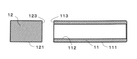
- FIG. 4 is an explanatory view showing a state before the cylindrical portion and the bottom portion are diffusion-bonded;
- the sample tube for a nuclear magnetic resonance apparatus of the present disclosure the first facing surface of the cylindrical portion facing the bottom and the second facing surface of the bottom facing the cylindrical portion are diffusion-bonded. Therefore, the sample tube for a nuclear magnetic resonance apparatus of the present disclosure can reduce eccentricity even when rotated, and can improve the resolution of the nuclear magnetic resonance apparatus.
- sample tube for a nuclear magnetic resonance (NMR) apparatus according to one embodiment of the present disclosure will be described based on FIGS.
- An NMR apparatus sample tube (hereinafter, the NMR apparatus sample tube may be simply referred to as “sample tube”) 1 according to one embodiment shown in FIG.
- the tubular portion 11 has a cylindrical shape and contains ceramics.
- ceramics include ceramics containing aluminum oxide, yttrium oxide, yttrium aluminum composite oxide, magnesium oxide, silicon carbide, silicon nitride, zirconium oxide, titanium oxide, and sialon as main components.
- ceramics containing aluminum oxide as a main component are preferable.
- main component means a component contained at a rate of 80% by mass or more when the total of the components constituting the ceramics is 100% by mass.
- Each component contained in the ceramics is identified by an X-ray diffractometer using CuK ⁇ rays, and the content of each component may be determined by, for example, an ICP (Inductively Coupled Plasma) emission spectrometer or a fluorescent X-ray spectrometer.
- ICP Inductively Coupled Plasma
- the cost of the sample tube 1 can be reduced by using ceramics whose main component is aluminum oxide.
- the ceramics When the ceramics is mainly composed of aluminum oxide, it may contain oxides of magnesium, calcium, silicon, sodium and the like.
- the size of the tubular portion 11 is set in consideration of the size of a general sample tube.
- the cylindrical portion 11 has, for example, an outer diameter of 2 mm or more and 5 mm or less, an inner diameter of 1.5 mm or more and 4 mm or less, and a length of 8 mm or more and 20 mm or less.
- the bottom part 12 is a member that seals one end of the cylindrical part 11 and contains ceramics.
- Ceramics are not limited, and similar to the cylindrical portion 11, for example, aluminum oxide, yttrium oxide, yttrium-aluminum composite oxide, magnesium oxide, silicon carbide, silicon nitride, zirconium oxide, titanium oxide, sialon, etc., as a main component Ceramics can be mentioned. Among these ceramics, ceramics containing aluminum oxide as a main component are preferable. When the ceramics is mainly composed of aluminum oxide, it may contain oxides of magnesium, calcium, silicon, sodium and the like.
- the tubular portion 11 and the bottom portion 12 may be made of the same main component ceramics, or may be made of different main component ceramics. Considering productivity and the like, it is preferable that the cylindrical portion 11 and the bottom portion 12 are made of ceramics having the same main component.
- the size of the bottom part 12 is set in consideration of the size of a general sample tube. As described above, since the bottom portion 12 is a member that seals one end of the cylindrical portion 11 , the outer diameter of the bottom portion 12 is designed to match the outer diameter of the cylindrical portion 11 .
- the thickness of the bottom portion 12 is, for example, 2 mm or more and 10 mm or less.
- the bottom part 12 has a disk shape or a columnar shape depending on the thickness.
- the tubular portion 11 and the bottom portion 12 are diffusion-bonded. Specifically, as shown in FIGS. 2 and 3, the first facing surface 113 of the cylindrical portion 11 facing the bottom portion 12 and the second facing surface 123 of the bottom portion 12 facing the cylindrical portion 11 are diffusion-bonded.
- the tubular portion 11 and the bottom portion 12 are not integrally molded. As shown in FIG. 3, large warpage of the outer peripheral surface 111 of the cylindrical portion 11 and variations in shape tolerances of the inner peripheral surface 112, such as straightness, circularity, and cylindricity, can be suppressed before diffusion bonding. The degree of coaxiality of the outer peripheral surface 111 with respect to the rotation axis of the cylindrical portion 11 can also be reduced. As a result, the resulting sample tube 1 can sufficiently reduce eccentricity even when rotated. Furthermore, the combination of the tubular portion 11 and the bottom portion 12 can be adjusted according to the required cost and the type of sample. As a result, the degree of freedom in design is also improved.
- the outer peripheral surface 111 of the cylindrical portion 11 and the outer peripheral surface 121 of the bottom portion 12 may have a smaller average cut level difference (R ⁇ c) than the inner peripheral surface 112 of the cylindrical portion 11, which is the difference between the cut level at a load length rate of 25% on the roughness curve and the cut level at a load length rate of 75% on the roughness curve.
- R ⁇ c average cut level difference
- the outer peripheral surface 111 of the tubular portion 11 and the outer peripheral surface 121 of the bottom portion 12 are less uneven than the inner peripheral surface 112 of the tubular portion 11 .
- the unevenness of the outer peripheral surface 111 of the cylindrical portion 11 and the outer peripheral surface 121 of the bottom portion 12 is reduced, even if the gas for rotation is supplied toward the outer peripheral surface 111 of the cylindrical portion 11, turbulence is less likely to occur. Therefore, the rotation of the sample tube 1 can be stabilized in a short time. As a result, sample analysis efficiency can be improved. Furthermore, the inner peripheral surface 112 of the cylindrical portion 11 has moderate unevenness, and the contact angle between the inner peripheral surface 112 and the liquid is reduced, thereby improving the hydrophilicity (wettability). As a result, when the sample is washed after being analyzed, residue of the washing liquid is less likely to adhere to the inner peripheral surface 112 of the cylindrical portion 11 .
- the cutting level difference (R ⁇ c) on the roughness curve is an index indicating the difference in the height direction between the cutting levels C (Rrm1) and C (Rrm2) corresponding to the load length ratios Rmr1 and Rmr2 on the roughness curve defined in JIS B0601:2001.
- a smaller value of the cutting level difference (R ⁇ c) in the roughness curve indicates a smoother surface with less unevenness.
- the cutting level difference (R ⁇ c) conforms to JIS B 0601:2001 and can be measured using a laser microscope (manufactured by Keyence Corporation, an ultra-depth color 3D shape measuring microscope (VK-X1000 or its successor model)).
- the illumination method is coaxial illumination
- the measurement magnification is 480 times
- the cutoff value ⁇ s is absent
- the cutoff value ⁇ c is 0.08 mm
- the end effect is corrected.
- the length of one line to be measured is, for example, 560 ⁇ m.
- Three measurement ranges are set from the outer peripheral surface 111 of the cylindrical portion 11, the outer peripheral surface 121 of the bottom portion 12, and the inner peripheral surface 112 of the cylindrical portion 11, respectively.
- the average value of the cut level difference (R ⁇ c), which is the difference between the cut level at the load length ratio of 25% on the roughness curve and the cut level at the load length ratio of 75% on the roughness curve, may be 0.07 ⁇ m or less (excluding 0 ⁇ m).
- the inner peripheral surface 112 of the tubular portion 11 may have a larger mean value of the root-mean-square slope (R ⁇ q) of the roughness curve than the outer peripheral surface 111 of the tubular portion 11 and the outer peripheral surface 121 of the bottom portion 12.
- R ⁇ q root-mean-square slope
- the inner peripheral surface 112 of the cylindrical portion 11 has moderate unevenness, and the contact angle between the inner peripheral surface 112 and the liquid is reduced, thereby improving the hydrophilicity (wettability).
- residue of the washing liquid is less likely to adhere to the inner peripheral surface 112 of the cylindrical portion 11 .
- the root-mean-square slope (R ⁇ q) conforms to JIS B 0601:2001 and can be measured using a shape analysis laser microscope (manufactured by Keyence Corporation, an ultra-depth color 3D shape measuring microscope (VK-X1100 or its successor model)).
- the measurement conditions are the same as those used in the measurement of the cutting level difference (R ⁇ c).
- the average value of the root-mean-square slope (R ⁇ q) of the roughness curve may be 0.07 or less (excluding 0).
- the outer peripheral surface 111 of the cylindrical portion 11 and the outer peripheral surface 121 of the bottom portion 12 may have a larger average cut level difference (R ⁇ c) than the inner peripheral surface 112 of the cylindrical portion 11, which is the difference between the cut level at a load length rate of 25% on the roughness curve and the cut level at a load length rate of 75% on the roughness curve.
- R ⁇ c average cut level difference
- the outer peripheral surface 111 of the tubular portion 11 and the outer peripheral surface 121 of the bottom portion 12 are more uneven than the inner peripheral surface 112 of the tubular portion 11 .
- the inner peripheral surface 112 of the cylindrical portion 11 can be a glossy surface with less unevenness. As a result, when the sample is powder, even if the dirt adheres to the inner peripheral surface 112 of the cylindrical portion 11, it can be easily found and removed.
- the average value of the cutting level difference (R ⁇ c) which is the difference between the cutting level at the load length ratio of 25% on the roughness curve and the cutting level at the load length ratio of 75% on the roughness curve, is 0. It may be 4 ⁇ m or less (excluding 0 ⁇ m).
- the inner peripheral surface 112 of the tubular portion 11 may have a smaller mean value of the root-mean-square slope (R ⁇ q) of the roughness curve than the outer peripheral surface 111 of the tubular portion 11 and the outer peripheral surface 121 of the bottom portion 12.
- R ⁇ q root-mean-square slope
- the average value of the root-mean-square slope (R ⁇ q) of the roughness curve may be 0.07 or less (excluding 0).
- At least one of the second facing surface 123, the outer peripheral surface 111 of the tubular portion 11, the inner peripheral surface 112 of the tubular portion 11, and the outer peripheral surface 121 of the bottom portion 12 may be a polished surface. Furthermore, the grain boundary phase on the polished surface may be etched. The grain boundary phase of the polished surface is recessed from the crystal grains when etched. Therefore, the etching process reduces the contact angle with pure water and improves the hydrophilicity. As a result, dirt can be removed efficiently when washed with a water-soluble cleaning liquid.
- the polishing method is not limited, and when the second facing surface 123 is used as the polishing surface, lapping polishing, magnetic fluid polishing, chemical mechanical polishing, and the like can be mentioned, for example.
- lapping polishing, magnetic fluid polishing, chemical mechanical polishing, and the like can be mentioned, for example.
- the outer peripheral surface 111 of the cylindrical portion 11 and the outer peripheral surface 121 of the bottom portion 12 are to be polished, for example, after centerless grinding, mirror polishing using a wrapping film, magnetic fluid polishing, and polishing using a pin (hereinafter, polishing using this pin may be referred to as pin polishing) may be performed.
- the inner peripheral surface 112 of the tubular portion 11 is to be a polished surface, for example, it may be honed and then pin-polished.
- the etching treatment include thermal etching treatment and chemical etching treatment.
- the method of manufacturing the sample tube 1 is not limited, and includes, for example, a step of applying water to at least one of the first facing surface 113 of the cylindrical portion 11 and the second facing surface 123 of the bottom portion 12, pressing the cylindrical portion 11 and the bottom portion 12 together after adsorbing them, and performing heat treatment by pressing them from the axial direction. Specifically, it is manufactured by the following procedure.
- the tubular portion 11 When the main component of the ceramics forming the tubular portion 11 is aluminum oxide, powders of aluminum oxide (having a purity of 99.9% by mass or more), magnesium hydroxide, silicon oxide, calcium carbonate, and chromium oxide, and a solvent (ion-exchanged water) are put into a pulverizing mill.
- aluminum oxide having a purity of 99.9% by mass or more
- magnesium hydroxide magnesium hydroxide
- silicon oxide silicon oxide
- calcium carbonate calcium carbonate
- chromium oxide chromium oxide
- a solvent ion-exchanged water
- Organic binders include, for example, acrylic emulsion, polyvinyl alcohol, polyethylene glycol, and polyethylene oxide.
- the content of magnesium hydroxide powder is 1.5% by mass or more and 1.9% by mass or less
- the content of silicon oxide powder is 5.4% or more and 5.8% or less by mass
- the content of calcium carbonate powder is 1.0% or more and 1.4% or less by mass
- the content of chromium oxide powder is 3.7% or more and 4.1% or less by mass
- the balance is aluminum oxide powder and unavoidable impurities.
- the total content of unavoidable impurities shall be 0.1% by mass or less.
- the granules are filled into a mold and pressed using a uniaxial press molding device or a cold isostatic press molding device to obtain a cylindrical compact.
- the molding pressure is, for example, 78 MPa or more and 128 MPa or less.
- a cylindrical sintered body is obtained by sintering this compact under the conditions of 1500° C. to 1700° C. and 4 hours to 6 hours in an air atmosphere.
- the cylindrical sintered body has, for example, an outer diameter of 2 mm or more and 5 mm or less, an inner diameter of 1.5 mm or more and 4 mm or less, and a length of 8 mm or more and 20 mm or less.
- 0.3 parts by mass or more and 5.0 parts by mass or less of aluminum oxide powder is added to 100 parts by mass of zirconium oxide powder produced by a coprecipitation method in which the amount of yttrium oxide as a stabilizer is 1 mol% or more and less than 3 mol%.
- ion-exchanged water as a solvent is added, and mixed and pulverized by a vibration mill or a ball mill.
- the average particle size of the zirconium oxide powder is preferably 0.05 ⁇ m or more and less than 0.5 ⁇ m, and the average particle size of the aluminum oxide powder is preferably 0.5 ⁇ m or more and 2.0 ⁇ m or less.
- the average particle size of the aluminum oxide powder is preferably 0.5 ⁇ m or more and 2.0 ⁇ m or less.
- White ceramic balls made of zirconium oxide, aluminum oxide, or zirconium oxide and aluminum oxide are preferably used for the mixed pulverization. ⁇ 99.5 ⁇ % ⁇ (ZrO 2 )91mol% ⁇ 99mol% ⁇ (Y 2 O 3 ) ⁇ (HfO 2 ) ⁇ (CeO 2 ) ⁇ (MgO) ⁇ (CaO) ⁇ 1 ⁇ 1mol% ⁇ 9mol% ⁇ 99.5 ⁇ % ⁇ (Al 2 O 3 ) ⁇ 1 ⁇ % ⁇ 40 ⁇ % ⁇ 99.5 ⁇ % ⁇
- Organic binders include, for example, acrylic emulsion, polyvinyl alcohol, polyethylene glycol, and polyethylene oxide.
- the obtained granules are filled into a mold and a molded body is obtained in the same manner as described above.
- a cylindrical sintered body is obtained by sintering this compact under the conditions of 1350° C. to 1550° C. and 4 hours to 6 hours in an air atmosphere.
- the cylindrical sintered body has the same size as described above.
- a cylindrical sintered body may be obtained by firing a cylindrical molded body, and the obtained cylindrical sintered body may be subjected to a grinding process to form a cylindrical sintered body.
- the inner periphery of the obtained cylindrical sintered body is subjected to polishing or the like as necessary to obtain the cylindrical portion 11 .
- the bottom portion 12 is also basically manufactured in the same procedure as the tubular portion 11 . Specifically, the same powder as the powder used to obtain the tubular portion 11 is used, the slurry is spray granulated to obtain granules, and then a disk-shaped (column depending on the thickness) is obtained in the same procedure as for the tubular portion 11.
- the main component of the molded body is aluminum oxide
- the molded body is fired in an air atmosphere under the conditions of 1500° C. or more and 1700° C. or less and 4 hours or more and 6 hours or less to obtain a disk-shaped (columnar) sintered body.
- the compact is sintered in an air atmosphere at 1350° C. or higher and 1550° C. or lower for 4 hours or longer and 6 hours or shorter to obtain a disk-shaped (columnar) sintered body.
- the outer diameter of the disk-shaped (columnar) sintered body is designed to match the outer diameter of the tubular portion 11 .
- the thickness of the disk-shaped (cylindrical) sintered body is, for example, 2 mm or more and 10 mm or less.
- the sample tube 1 is obtained by diffusion bonding the tubular portion 11 and the bottom portion 12 thus obtained. Specifically, the sample tube 1 is obtained by applying water to at least one of the first facing surface 113 of the cylindrical portion 11 and the second facing surface 123 of the bottom portion 12, adsorbing the cylindrical portion 11 and the bottom portion 12, pressing them from the axial direction, and subjecting them to heat treatment.
- the pressure may be applied by the weight of the cylindrical portion 11 or the bottom portion 12, for example.
- the holding temperature is 1350 ° C. or higher and 1550 ° C. or lower, and the holding time is 1 hour or more and 3 hours or less.
- At least one of the first facing surface 113 of the tubular portion 11 and the second facing surface 123 of the bottom portion 12 may be polished before heat treatment.
- the polished surface may be subjected to an etching treatment such as a thermal etching treatment. By etching, the grain boundary phase on the polished surface recedes from the crystal grains toward the inside by about several tens of nanometers, so the contact angle between the polished surface and the liquid is reduced and the hydrophilicity (wettability) is improved.
- At least one of the outer circumference of the cylindrical portion 11 and the outer circumference of the bottom portion 12 may be subjected to a grinding treatment or a polishing treatment as necessary to form the outer circumferential surface 111 of the cylindrical portion 11 and the outer circumferential surface 121 of the bottom portion 12.
- a grinding treatment or a polishing treatment as necessary to form the outer circumferential surface 111 of the cylindrical portion 11 and the outer circumferential surface 121 of the bottom portion 12.
- the outer circumferences of the cylindrical portion 11 and the bottom portion 12 are ground after diffusion bonding.
- polishing may be performed using a slurry containing abrasive grains having an average particle size D50 smaller than that of the abrasive grains used for processing the inner circumference of the cylindrical portion 11 .
- the material of the abrasive grains includes, for example, diamond, etc., including the later-described polishing treatment.
- polishing is performed before diffusion bonding. After that, polishing may be performed using a slurry containing abrasive grains having an average particle diameter D50 of 4 ⁇ m or less, for example.
- the inner periphery of the tubular portion 11 is ground before diffusion bonding. After that, polishing may be performed using a slurry containing abrasive grains having a larger average particle diameter D50 than the abrasive grains used for processing the outer circumferences of the cylindrical portion 11 and the bottom portion 12 .
- the outer periphery of the cylindrical portion 11 and the bottom portion 12 may be polished with a slurry containing abrasive grains having a larger average particle size D50 than the abrasive grains used in the treatment of the inner periphery of the cylindrical portion 11.
- the diffusion bonding is followed by grinding. After that, polishing may be performed using a slurry containing abrasive grains having an average particle diameter D50 of, for example, 8 ⁇ m or more and 10 ⁇ m or less.
- the inner peripheral surface of the tubular portion 11 is ground before diffusion bonding.
- polishing may be performed using a slurry containing abrasive grains having an average particle diameter D50 smaller than that of the abrasive grains used for processing the outer circumferences of the cylindrical portion 11 and the bottom portion 12 .
- a slurry containing abrasive grains having an average particle diameter D50 of, for example, 1 ⁇ m or less may be used and the polishing time may be set to 50 seconds or longer.
- the polished surface may be subjected to etching treatment such as thermal etching treatment.
- etching treatment such as thermal etching treatment.
- the sample tube 1 obtained in this manner large warpage of the outer peripheral surface 111 of the cylindrical portion 11 and variation in shape tolerance of the inner peripheral surface 112 can be suppressed before diffusion bonding. As a result, the resulting sample tube 1 can sufficiently reduce eccentricity even when rotated. Furthermore, the combination of the tubular portion 11 and the bottom portion 12 can be adjusted according to the required cost and the type of sample. As a result, the degree of freedom in design is also improved.
- a sample tube according to the present disclosure is a member included in a nuclear magnetic resonance (NMR) apparatus. Specifically, it is included in a bearing unit provided in the NMR apparatus.
- NMR nuclear magnetic resonance
- the bearing unit includes a sample tube according to the present disclosure and bearings supporting both axial ends of the sample tube.
- the bearing is made of ceramics containing, for example, zirconium oxide or aluminum oxide as a main component.
- the NMR apparatus including the sample tube according to the present disclosure can reduce eccentricity even when the sample tube is rotated, and can improve the resolution of the nuclear magnetic resonance apparatus.
- Example 1 2.7 parts by mass of aluminum oxide powder was added to 100 parts by mass of zirconium oxide powder produced by a coprecipitation method with the addition amount of yttrium oxide as a stabilizer being 2 mol% and mixed, and ion-exchanged water as a solvent was added to a ball mill and mixed and pulverized with balls made of zirconium oxide having a purity of 99.5% by mass or more.
- the average particle size of the zirconium oxide powder was set to 0.28 ⁇ m, and the average particle size of the aluminum oxide powder was set to 1.3 ⁇ m.
- a predetermined amount of paraffin wax was added as a binder, followed by spray drying with a spray dryer to obtain granules.
- the obtained granules were filled into a mold and pressed using a uniaxial press molding device to obtain a cylindrical molded body and a disk-shaped molded body.
- the molding pressure was 98 Ma.
- These molded bodies were fired in an air atmosphere at a holding temperature of 1450° C. for a holding time of 5 hours to obtain a cylindrical part as a cylindrical sintered body and a bottom part as a disk-shaped sintered body.
- the inner periphery of the tubular portion was honed as follows.
- the cylindrical portion was kept rotating at 2000 rpm with the axis of the cylindrical portion as the rotation axis.
- the rotation axis of the grinding tool was tilted by 1.8° with respect to the rotation axis of the outer peripheral surface of the cylindrical portion, and the grinding tool was rotated at 120000 rpm in the direction opposite to the rotation direction of the cylindrical portion.
- the inner peripheral surface of the tubular portion was ground by honing by reciprocating the grinding tool in contact with the inner peripheral surface of the tubular portion along the axial direction of the tubular portion.
- a tool having an outer diameter of 1.8 mm and diamond abrasive grains having an average particle diameter of 20 ⁇ m fixed to the tip was used.
- the inner periphery of a portion of the cylindrical portion was pin-polished using a pin coated with a slurry containing diamond abrasive grains having an average particle size shown in Table 1.
- Some of the cylindrical portions are sample Nos. 3 to 5 shown in Table 1, and sample Nos. Cylindrical portions 1 and 2 were not pin-polished.
- One end surface of the tubular portion and the main surface of the bottom facing this end surface were lapping-polished to form a first opposing surface and a second opposing surface, respectively.
- the cylindrical portion had a length of 11 mm, an inner diameter of 2 mm, and an outer diameter of 3.2 mm.
- the thickness of the bottom was 5 mm and the outer diameter was 3.2 mm.
- the tubular portion and the bottom portion were diffusion-bonded with the first facing surface and the second facing surface facing each other.
- the holding temperature for diffusion bonding was 1450° C., and the holding time was 2 hours.
- the outer circumference of the cylindrical part and the outer circumference of the bottom part were centerless ground.
- the outer circumference, the inner circumference, and the outer circumference of the bottom of the tubular portion were pin-polished to obtain the outer peripheral surface of the tubular portion, the inner peripheral surface of the tubular portion, and the outer peripheral surface of the bottom.
- the sample tube obtained by this pin polishing is Sample No. 3-5.
- the polishing time is as shown in Table 1.
- a cylindrical sintered body with a bottom was produced by filling the above granules into a mold, molding them integrally, and firing them.
- the outer periphery of this sintered body was centerless ground, and a sample tube obtained by pin polishing using a pin coated with a slurry containing diamond abrasive grains having an average particle size shown in Table 1 was designated as Sample No. 1.
- the grinding amount (grinding depth) of the outer periphery by centerless grinding is as follows. 1 to 5 were set to be the same.
- the cutting level difference (R ⁇ c) which is the difference between the cutting level at a load length ratio of 25% on the roughness curve of the outer peripheral surface of the cylindrical portion, the outer peripheral surface of the bottom portion, and the inner peripheral surface of the cylindrical portion and the cutting level at a load length ratio of 75% on the roughness curve, was measured and the average value was obtained.
- R ⁇ c The cutting level difference
- the method for measuring the cutting level difference (R ⁇ c) is the method described above.
- the coaxiality of the outer peripheral surface with respect to the rotation axis of the tubular portion was measured using a coaxiality measuring instrument in accordance with JIS B 0621:1984.
- the axis of rotation of the cylindrical portion is the datum axis straight line defined by JIS B 0621:1984.
- the surface condition of the inner peripheral surface was visually observed.
- Table 1 shows the average value of the cutting level difference (R ⁇ c), the measured values of the coaxiality, and the observation results of the surface state.
- Sample No. 2 to 6 the outer peripheral surface of the cylindrical portion and the outer peripheral surface of the bottom have a smaller average value of the cutting level difference (R ⁇ c) than the inner peripheral surface of the cylindrical portion. Therefore, sample no. 2 to 6, it can be said that the degree of coaxiality of the outer peripheral surface with respect to the rotation axis of the cylindrical portion is small. Therefore, even if the gas for rotation is supplied toward the outer peripheral surfaces of the cylindrical portion and the bottom portion, turbulence is less likely to occur, and it can be said that the analysis efficiency of the sample can be improved.
- Example 2 The inner circumference of the cylindrical portion obtained by the same manufacturing method as that shown in Example 1 was honed. After honing, the inner periphery of the tubular portion was pin-polished using a pin coated with a slurry containing diamond abrasive grains having an average particle diameter shown in Table 2. One end surface of the tubular portion and the main surface of the bottom facing this end surface were lapping-polished to form a first opposing surface and a second opposing surface, respectively. The bottom was obtained by the same manufacturing method as shown in Example 1.
- the cylindrical portion and the bottom portion were diffusion-bonded by the same manufacturing method as shown in Example 1.
- the outer circumference of the cylindrical part and the outer circumference of the bottom part were centerless ground.
- using a pin coated with a slurry containing diamond abrasive grains having an average particle diameter shown in Table 2 the outer circumference of the tubular portion, the inner circumference of the tubular portion, and the outer circumference of the bottom portion were pin-polished. 7-11 were obtained.
- the polishing time is as shown in Table 2.
- the root-mean-square slope (R ⁇ q) and coaxiality were obtained by the same method as shown in Example 1.
- the surface condition of the inner peripheral surface was visually observed, and the contact angle with respect to pure water was measured.
- the contact angle of pure water with respect to the inner peripheral surface was determined by the sessile drop method described in JIS R 3257:1999.
- Table 2 shows the average value of the root-mean-square slope (R ⁇ q), the measured value of coaxiality, the observation result of the surface state, and the contact angle of pure water with respect to the inner peripheral surface.
- the inner peripheral surface of the cylindrical portion of Samples Nos. 8 to 11 has a larger average root-mean-square slope (R ⁇ q) than the outer peripheral surface of the cylindrical portion and the outer peripheral surface of the bottom portion. Therefore, sample no. In Nos. 8 to 11, the degree of coaxiality between the outer peripheral surface of the cylindrical portion and the outer peripheral surface of the bottom portion is small, and the contact angle of pure water with respect to the inner peripheral surface is small, improving hydrophilicity (wettability). As a result, it can be said that cleaning the sample after analysis makes it difficult for the residue of the cleaning liquid to adhere to the inner peripheral surface.
- sample No. In Nos. 9 to 11 the average value of the root-mean-square inclination (R ⁇ q) of the inner circumferential surface of the cylindrical portion is 0.07 or less.
- the inner peripheral surface exhibits a mirror surface, and when the sample is a powder, it can be said that it is possible to reduce the adhesion of contaminants to concave portions such as open pores on the inner peripheral surface.
- Example 3 The inner circumference of the cylindrical portion obtained by the same manufacturing method as that shown in Example 1 was honed. After honing, the inner periphery of the cylindrical portion was pin-polished using a pin coated with a slurry containing diamond abrasive grains having an average particle diameter shown in Table 3. One end surface of the cylindrical portion and the main surface of the bottom facing this end surface were lapping-polished to form a first opposing surface and a second opposing surface, respectively. The bottom was obtained by the same manufacturing method as shown in Example 1.
- the cylindrical portion and the bottom portion were diffusion-bonded by the same manufacturing method as shown in Example 1.
- the outer circumference of the cylindrical part and the outer circumference of the bottom part were centerless ground.
- using a pin coated with a slurry containing diamond abrasive grains having an average particle size shown in Table 3 the outer circumference of the tubular portion, the inner circumference of the tubular portion, and the outer circumference of the bottom portion were pin-polished. 12-15 were obtained.
- the polishing time is as shown in Table 3.
- the cutting level difference (R ⁇ c) and coaxiality were obtained by the same method as shown in Example 1.
- the surface conditions of the outer peripheral surface of the tubular portion, the inner peripheral surface of the tubular portion, and the outer peripheral surface of the bottom portion were visually observed.
- Table 3 shows the average value of the cutting level difference (R ⁇ c), the measured values of the coaxiality, and the observation results of the surface state.
- the outer peripheral surface of the cylindrical portion and the outer peripheral surface of the bottom of Sample Nos. 13 to 15 have a larger average cutting level difference (R ⁇ c) than the inner peripheral surface of the cylindrical portion, and each of these outer peripheral surfaces is a non-mirror surface. Therefore, sample no.
- the cylindrical portions 13 to 15 and the outer peripheral surface of the bottom exhibit a sufficient anchoring effect when forming a thin film such as a coil. As a result, it can be said that the thin film becomes difficult to peel off.
- the inner peripheral surface of the cylindrical portion is a mirror surface, it is a glossy surface with less unevenness. If the sample is powder, even if the dirt sticks to the inner peripheral surface of the cylindrical portion, it can be easily found and removed.
- the average cutting level difference (R.delta.c) of the outer peripheral surface of the cylindrical portion is 0.4 .mu.m or less, so that the unevenness present on the outer peripheral surface is appropriately controlled. Therefore, even if the gas for rotation is supplied toward the outer peripheral surface, turbulence is less likely to occur. As a result, it can be said that the rotation of the sample tube 1 can be stabilized in a short time, and the sample analysis efficiency can be improved.
- Example 4 The inner circumference of the cylindrical portion obtained by the same manufacturing method as that shown in Example 1 was honed. After honing, the outer periphery of the tubular portion, the inner periphery of the tubular portion, and the outer periphery of the bottom portion were pin-polished using a pin coated with a slurry containing diamond abrasive grains having an average particle size shown in Table 4. One end surface of the cylindrical portion and the main surface of the bottom facing this end surface were lapping-polished to form a first opposing surface and a second opposing surface, respectively. The bottom was obtained by the same manufacturing method as shown in Example 1.
- Example 2 the cylindrical portion and the bottom portion were diffusion-bonded by the same manufacturing method as shown in Example 1.
- the outer periphery of the cylindrical portion and the outer periphery of the bottom portion were subjected to centerless grinding, and then, using a pin coated with a slurry containing diamond abrasive grains having an average particle diameter shown in Table 4, the outer periphery of the cylindrical portion, the inner periphery of the cylindrical portion, and the outer periphery of the bottom portion were pin-polished.
- Sample tubes having the outer peripheral surface of the tubular portion, the inner peripheral surface of the tubular portion, and the outer peripheral surface of the bottom portion, respectively, are referred to as sample Nos. 16-20 were obtained.
- the polishing time is as shown in Table 4.
- the root-mean-square slope (R ⁇ q) and coaxiality were determined in the same manner as shown in Example 1. The surface condition of the inner peripheral surface was visually observed. Table 4 shows the average values of the root-mean-square slope (R ⁇ q), the measured values of coaxiality, and the observation results of the surface state.
- the inner peripheral surfaces of the cylindrical portions 17 to 20 have smaller average values of the root-mean-square slope (R ⁇ q) than the outer peripheral surfaces of the cylindrical portions and the outer peripheral surfaces of the bottom portions. Therefore, the inner peripheral surface of the cylindrical portion becomes a glossy surface with less unevenness. As a result, when the sample is powder, even if the dirt adheres to the inner peripheral surface of the cylindrical portion, it can be said that it can be easily found and removed.
- sample tube for nuclear magnetic resonance (NMR) equipment (sample tube) REFERENCE SIGNS LIST 11 tubular portion 111 outer peripheral surface of tubular portion 112 inner peripheral surface of tubular portion 113 first opposing surface 12 bottom portion 121 outer peripheral surface of bottom portion 123 second opposing surface
Landscapes
- Chemical & Material Sciences (AREA)
- Engineering & Computer Science (AREA)
- Ceramic Engineering (AREA)
- Organic Chemistry (AREA)
- Materials Engineering (AREA)
- Structural Engineering (AREA)
- Composite Materials (AREA)
- Physics & Mathematics (AREA)
- Mechanical Engineering (AREA)
- Manufacturing & Machinery (AREA)
- Condensed Matter Physics & Semiconductors (AREA)
- General Physics & Mathematics (AREA)
- Finish Polishing, Edge Sharpening, And Grinding By Specific Grinding Devices (AREA)
Priority Applications (2)
| Application Number | Priority Date | Filing Date | Title |
|---|---|---|---|
| JP2023575206A JP7678149B2 (ja) | 2022-01-18 | 2023-01-10 | 核磁気共鳴装置用サンプルチューブ |
| EP23743142.4A EP4467273A4 (en) | 2022-01-18 | 2023-01-10 | SAMPLE TUBE FOR NUCLEAR MAGNETIC RESONANCE EQUIPMENT |
Applications Claiming Priority (2)
| Application Number | Priority Date | Filing Date | Title |
|---|---|---|---|
| JP2022005447 | 2022-01-18 | ||
| JP2022-005447 | 2022-01-18 |
Publications (1)
| Publication Number | Publication Date |
|---|---|
| WO2023140147A1 true WO2023140147A1 (ja) | 2023-07-27 |
Family
ID=87348731
Family Applications (1)
| Application Number | Title | Priority Date | Filing Date |
|---|---|---|---|
| PCT/JP2023/000316 Ceased WO2023140147A1 (ja) | 2022-01-18 | 2023-01-10 | 核磁気共鳴装置用サンプルチューブ |
Country Status (3)
| Country | Link |
|---|---|
| EP (1) | EP4467273A4 (https=) |
| JP (1) | JP7678149B2 (https=) |
| WO (1) | WO2023140147A1 (https=) |
Citations (13)
| Publication number | Priority date | Publication date | Assignee | Title |
|---|---|---|---|---|
| JPS6079292A (ja) * | 1983-10-06 | 1985-05-07 | 株式会社東芝 | 制御棒水圧駆動装置 |
| JPS61201675A (ja) * | 1985-03-05 | 1986-09-06 | 石川島播磨重工業株式会社 | セラミツクス管の接合方法 |
| JPS635887A (ja) * | 1986-06-24 | 1988-01-11 | Hitachi Ltd | 異種材料の管の接合方法 |
| JPH01289582A (ja) * | 1988-05-17 | 1989-11-21 | Ishikawajima Harima Heavy Ind Co Ltd | 異種金属の接合方法とその継手 |
| JPH05269595A (ja) * | 1992-03-24 | 1993-10-19 | Tokai Rubber Ind Ltd | ホース口金製造用加圧治具 |
| JPH0919713A (ja) * | 1995-07-04 | 1997-01-21 | Daido Steel Co Ltd | 硬質層内装長尺複合金属管の製造方法 |
| JP2003073177A (ja) * | 2001-08-31 | 2003-03-12 | Kyocera Corp | セラミック接合装置及びこれを用いたセラミック接合体の製造方法。 |
| JP2003165779A (ja) * | 2001-11-29 | 2003-06-10 | Kyocera Corp | セラミック接合装置及びこれを用いたセラミック接合体の製造方法。 |
| JP2004518558A (ja) * | 2001-01-31 | 2004-06-24 | イー・アイ・デュポン・ドウ・ヌムール・アンド・カンパニー | 湾曲した表面を有する、冶金的に接合された層状の物品 |
| JP2011095261A (ja) | 2009-10-29 | 2011-05-12 | Bruker Biospin Corp | 多孔質セラミック軸受を有するnmr用masのロータアセンブリ |
| WO2021015092A1 (ja) * | 2019-07-25 | 2021-01-28 | 京セラ株式会社 | 成形型およびその製造方法 |
| JP2021196198A (ja) * | 2020-06-10 | 2021-12-27 | 京セラ株式会社 | 反応容器および生化学分析装置 |
| WO2022163657A1 (ja) * | 2021-01-26 | 2022-08-04 | 京セラ株式会社 | 液体収容容器およびその製造方法 |
Family Cites Families (1)
| Publication number | Priority date | Publication date | Assignee | Title |
|---|---|---|---|---|
| JPS6079592A (ja) * | 1983-10-05 | 1985-05-07 | Hitachi Ltd | リフレツシユ回路 |
-
2023
- 2023-01-10 JP JP2023575206A patent/JP7678149B2/ja active Active
- 2023-01-10 EP EP23743142.4A patent/EP4467273A4/en active Pending
- 2023-01-10 WO PCT/JP2023/000316 patent/WO2023140147A1/ja not_active Ceased
Patent Citations (13)
| Publication number | Priority date | Publication date | Assignee | Title |
|---|---|---|---|---|
| JPS6079292A (ja) * | 1983-10-06 | 1985-05-07 | 株式会社東芝 | 制御棒水圧駆動装置 |
| JPS61201675A (ja) * | 1985-03-05 | 1986-09-06 | 石川島播磨重工業株式会社 | セラミツクス管の接合方法 |
| JPS635887A (ja) * | 1986-06-24 | 1988-01-11 | Hitachi Ltd | 異種材料の管の接合方法 |
| JPH01289582A (ja) * | 1988-05-17 | 1989-11-21 | Ishikawajima Harima Heavy Ind Co Ltd | 異種金属の接合方法とその継手 |
| JPH05269595A (ja) * | 1992-03-24 | 1993-10-19 | Tokai Rubber Ind Ltd | ホース口金製造用加圧治具 |
| JPH0919713A (ja) * | 1995-07-04 | 1997-01-21 | Daido Steel Co Ltd | 硬質層内装長尺複合金属管の製造方法 |
| JP2004518558A (ja) * | 2001-01-31 | 2004-06-24 | イー・アイ・デュポン・ドウ・ヌムール・アンド・カンパニー | 湾曲した表面を有する、冶金的に接合された層状の物品 |
| JP2003073177A (ja) * | 2001-08-31 | 2003-03-12 | Kyocera Corp | セラミック接合装置及びこれを用いたセラミック接合体の製造方法。 |
| JP2003165779A (ja) * | 2001-11-29 | 2003-06-10 | Kyocera Corp | セラミック接合装置及びこれを用いたセラミック接合体の製造方法。 |
| JP2011095261A (ja) | 2009-10-29 | 2011-05-12 | Bruker Biospin Corp | 多孔質セラミック軸受を有するnmr用masのロータアセンブリ |
| WO2021015092A1 (ja) * | 2019-07-25 | 2021-01-28 | 京セラ株式会社 | 成形型およびその製造方法 |
| JP2021196198A (ja) * | 2020-06-10 | 2021-12-27 | 京セラ株式会社 | 反応容器および生化学分析装置 |
| WO2022163657A1 (ja) * | 2021-01-26 | 2022-08-04 | 京セラ株式会社 | 液体収容容器およびその製造方法 |
Non-Patent Citations (2)
| Title |
|---|
| MAUL ANDREAS; BLUMLER PETER; HEIL WERNER; NIKIEL ANNA; OTTEN ERNST; PETRICH ANDREAS; SCHMIDT THOMAS: "Spherical fused silica cells filled with pure helium for nuclear magnetic resonance-magnetometry", REVIEW OF SCIENTIFIC INSTRUMENTS, AMERICAN INSTITUTE OF PHYSICS, 2 HUNTINGTON QUADRANGLE, MELVILLE, NY 11747, vol. 87, no. 1, 1 January 1901 (1901-01-01), 2 Huntington Quadrangle, Melville, NY 11747, XP012203723, ISSN: 0034-6748, DOI: 10.1063/1.4938251 * |
| See also references of EP4467273A4 |
Also Published As
| Publication number | Publication date |
|---|---|
| EP4467273A4 (en) | 2025-12-24 |
| JP7678149B2 (ja) | 2025-05-15 |
| EP4467273A1 (en) | 2024-11-27 |
| JPWO2023140147A1 (https=) | 2023-07-27 |
Similar Documents
| Publication | Publication Date | Title |
|---|---|---|
| JP5367080B2 (ja) | 大型セラミック転がり要素 | |
| US6589448B2 (en) | Ceramic ball for bearing and ceramic ball bearing using the same | |
| US20030008765A1 (en) | High-purity alumina sintered body, high-purity alumina ball, jig for semiconductor, insulator, ball bearing, check valve, and method for manufacturing high-purity alumina sintered body | |
| CN116161969B (zh) | 滑动构件及使用了其的轴承、发动机以及驱动装置 | |
| US6696376B2 (en) | Zirconia containing ceramic ball, method for manufacturing same, ceramic ball bearing and check valve | |
| CN111627790B (zh) | 半导体制造装置构件、半导体制造装置、显示器制造装置 | |
| JP2002036216A (ja) | セラミックボール、ボールベアリング、ベアリング付きモータ、ハードディスク装置、ポリゴンスキャナ及びセラミックボールの製造方法 | |
| WO2023140147A1 (ja) | 核磁気共鳴装置用サンプルチューブ | |
| JP2009179507A (ja) | 炭化珪素/窒化硼素複合材料焼結体、その製造方法およびその焼結体を用いた部材 | |
| CN118302847A (zh) | 高度调节构件、热处理装置和静电吸盘装置 | |
| US6619847B1 (en) | Ceramic dynamic-pressure bearing, motor having bearing, hard disk drive, and polygon scanner | |
| WO2021141056A1 (ja) | セラミック接合体、セラミック接合体の製造方法、流路切替弁用ステータおよび流路切替弁 | |
| JP5988370B2 (ja) | セラミック転動体 | |
| US6619848B2 (en) | Ceramic dynamic pressure bearing, motor with bearing, hard disc apparatus and polygon scanner | |
| JP2002266865A (ja) | セラミック動圧軸受、軸受付きモータ、ハードディスク装置及びポリゴンスキャナ | |
| WO2023210268A1 (ja) | ジルコニア質メディア、ベアリングボール及びそれらの製造方法 | |
| JP2002295477A (ja) | セラミック動圧軸受、軸受付きモータ、ハードディスク装置及びポリゴンスキャナ | |
| JP2002266850A (ja) | ハードディスク装置 | |
| JP2002106570A (ja) | 転動体およびこれを用いたベアリング | |
| JP4693677B2 (ja) | 動圧軸受およびこれを用いたモータ | |
| JP4567855B2 (ja) | 窒化珪素焼結体およびそれを用いた摺動部材 | |
| JP7601582B2 (ja) | セラミックス焼結体、ベアリングボール、および、ベアリング | |
| JP2002235746A (ja) | セラミック動圧軸受、軸受付きモータ、ハードディスク装置及びポリゴンスキャナ | |
| JP2001122667A (ja) | 窒化珪素質焼結部材、セラミックボール、ボールベアリング及びセラミック摺動部品 | |
| WO2025164541A1 (ja) | 摺動部材 |
Legal Events
| Date | Code | Title | Description |
|---|---|---|---|
| 121 | Ep: the epo has been informed by wipo that ep was designated in this application |
Ref document number: 23743142 Country of ref document: EP Kind code of ref document: A1 |
|
| ENP | Entry into the national phase |
Ref document number: 2023575206 Country of ref document: JP Kind code of ref document: A |
|
| WWE | Wipo information: entry into national phase |
Ref document number: 2023743142 Country of ref document: EP |
|
| NENP | Non-entry into the national phase |
Ref country code: DE |
|
| ENP | Entry into the national phase |
Ref document number: 2023743142 Country of ref document: EP Effective date: 20240819 |