WO2023140147A1 - Sample tube for nuclear magnetic resonance equipment - Google Patents
Sample tube for nuclear magnetic resonance equipment Download PDFInfo
- Publication number
- WO2023140147A1 WO2023140147A1 PCT/JP2023/000316 JP2023000316W WO2023140147A1 WO 2023140147 A1 WO2023140147 A1 WO 2023140147A1 JP 2023000316 W JP2023000316 W JP 2023000316W WO 2023140147 A1 WO2023140147 A1 WO 2023140147A1
- Authority
- WO
- WIPO (PCT)
- Prior art keywords
- peripheral surface
- cylindrical portion
- sample tube
- magnetic resonance
- nuclear magnetic
- Prior art date
Links
Images


Classifications
-
- B—PERFORMING OPERATIONS; TRANSPORTING
- B23—MACHINE TOOLS; METAL-WORKING NOT OTHERWISE PROVIDED FOR
- B23H—WORKING OF METAL BY THE ACTION OF A HIGH CONCENTRATION OF ELECTRIC CURRENT ON A WORKPIECE USING AN ELECTRODE WHICH TAKES THE PLACE OF A TOOL; SUCH WORKING COMBINED WITH OTHER FORMS OF WORKING OF METAL
- B23H5/00—Combined machining
- B23H5/06—Electrochemical machining combined with mechanical working, e.g. grinding or honing
-
- B—PERFORMING OPERATIONS; TRANSPORTING
- B23—MACHINE TOOLS; METAL-WORKING NOT OTHERWISE PROVIDED FOR
- B23K—SOLDERING OR UNSOLDERING; WELDING; CLADDING OR PLATING BY SOLDERING OR WELDING; CUTTING BY APPLYING HEAT LOCALLY, e.g. FLAME CUTTING; WORKING BY LASER BEAM
- B23K20/00—Non-electric welding by applying impact or other pressure, with or without the application of heat, e.g. cladding or plating
-
- C—CHEMISTRY; METALLURGY
- C04—CEMENTS; CONCRETE; ARTIFICIAL STONE; CERAMICS; REFRACTORIES
- C04B—LIME, MAGNESIA; SLAG; CEMENTS; COMPOSITIONS THEREOF, e.g. MORTARS, CONCRETE OR LIKE BUILDING MATERIALS; ARTIFICIAL STONE; CERAMICS; REFRACTORIES; TREATMENT OF NATURAL STONE
- C04B37/00—Joining burned ceramic articles with other burned ceramic articles or other articles by heating
-
- G—PHYSICS
- G01—MEASURING; TESTING
- G01N—INVESTIGATING OR ANALYSING MATERIALS BY DETERMINING THEIR CHEMICAL OR PHYSICAL PROPERTIES
- G01N24/00—Investigating or analyzing materials by the use of nuclear magnetic resonance, electron paramagnetic resonance or other spin effects
Definitions
- the present invention relates to a sample tube for a nuclear magnetic resonance apparatus.
- Nuclear Magnetic Resonance is a phenomenon in which atomic nuclei placed in an external magnetic field interact with electromagnetic waves of a unique frequency. NMR phenomena can be observed by NMR spectrometers and are used to study molecular physics, crystalline and amorphous materials. In particular, nuclear spin phenomena are used to generate spectra representing various spins and spin interactions.
- Patent Literature 1 describes a stator assembly to which the rotor (sample tube for nuclear magnetic resonance apparatus) as described above is mounted.
- a sample tube for a nuclear magnetic resonance apparatus includes a cylindrical tubular portion containing ceramics, and a bottom portion containing ceramics that seals one end of the tubular portion.
- a first facing surface of the cylindrical portion facing the bottom and a second facing surface of the bottom facing the cylindrical portion are diffusion-bonded.
- a bearing unit includes the above sample tube for a nuclear magnetic resonance apparatus, and a bearing that supports both axial ends of the sample tube for a nuclear magnetic resonance apparatus and is made of ceramics containing zirconium oxide or aluminum oxide as a main component.
- a nuclear magnetic resonance apparatus includes this bearing unit.
- a method for manufacturing a sample tube for a nuclear magnetic resonance apparatus includes a step of applying water to at least one of the first opposing surface of the tubular portion and the second opposing surface of the bottom portion, adsorbing the tubular portion and the bottom portion, and then applying pressure from the axial direction for heat treatment.
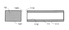
- FIG. 1 is a perspective view showing a sample tube for a nuclear magnetic resonance apparatus according to an embodiment of the present disclosure
- FIG. FIG. 2 is an explanatory view showing a cross section taken along line XX shown in FIG. 1
- FIG. 4 is an explanatory view showing a state before the cylindrical portion and the bottom portion are diffusion-bonded;
- the sample tube for a nuclear magnetic resonance apparatus of the present disclosure the first facing surface of the cylindrical portion facing the bottom and the second facing surface of the bottom facing the cylindrical portion are diffusion-bonded. Therefore, the sample tube for a nuclear magnetic resonance apparatus of the present disclosure can reduce eccentricity even when rotated, and can improve the resolution of the nuclear magnetic resonance apparatus.
- sample tube for a nuclear magnetic resonance (NMR) apparatus according to one embodiment of the present disclosure will be described based on FIGS.
- An NMR apparatus sample tube (hereinafter, the NMR apparatus sample tube may be simply referred to as “sample tube”) 1 according to one embodiment shown in FIG.
- the tubular portion 11 has a cylindrical shape and contains ceramics.
- ceramics include ceramics containing aluminum oxide, yttrium oxide, yttrium aluminum composite oxide, magnesium oxide, silicon carbide, silicon nitride, zirconium oxide, titanium oxide, and sialon as main components.
- ceramics containing aluminum oxide as a main component are preferable.
- main component means a component contained at a rate of 80% by mass or more when the total of the components constituting the ceramics is 100% by mass.
- Each component contained in the ceramics is identified by an X-ray diffractometer using CuK ⁇ rays, and the content of each component may be determined by, for example, an ICP (Inductively Coupled Plasma) emission spectrometer or a fluorescent X-ray spectrometer.
- ICP Inductively Coupled Plasma
- the cost of the sample tube 1 can be reduced by using ceramics whose main component is aluminum oxide.
- the ceramics When the ceramics is mainly composed of aluminum oxide, it may contain oxides of magnesium, calcium, silicon, sodium and the like.
- the size of the tubular portion 11 is set in consideration of the size of a general sample tube.
- the cylindrical portion 11 has, for example, an outer diameter of 2 mm or more and 5 mm or less, an inner diameter of 1.5 mm or more and 4 mm or less, and a length of 8 mm or more and 20 mm or less.
- the bottom part 12 is a member that seals one end of the cylindrical part 11 and contains ceramics.
- Ceramics are not limited, and similar to the cylindrical portion 11, for example, aluminum oxide, yttrium oxide, yttrium-aluminum composite oxide, magnesium oxide, silicon carbide, silicon nitride, zirconium oxide, titanium oxide, sialon, etc., as a main component Ceramics can be mentioned. Among these ceramics, ceramics containing aluminum oxide as a main component are preferable. When the ceramics is mainly composed of aluminum oxide, it may contain oxides of magnesium, calcium, silicon, sodium and the like.
- the tubular portion 11 and the bottom portion 12 may be made of the same main component ceramics, or may be made of different main component ceramics. Considering productivity and the like, it is preferable that the cylindrical portion 11 and the bottom portion 12 are made of ceramics having the same main component.
- the size of the bottom part 12 is set in consideration of the size of a general sample tube. As described above, since the bottom portion 12 is a member that seals one end of the cylindrical portion 11 , the outer diameter of the bottom portion 12 is designed to match the outer diameter of the cylindrical portion 11 .
- the thickness of the bottom portion 12 is, for example, 2 mm or more and 10 mm or less.
- the bottom part 12 has a disk shape or a columnar shape depending on the thickness.
- the tubular portion 11 and the bottom portion 12 are diffusion-bonded. Specifically, as shown in FIGS. 2 and 3, the first facing surface 113 of the cylindrical portion 11 facing the bottom portion 12 and the second facing surface 123 of the bottom portion 12 facing the cylindrical portion 11 are diffusion-bonded.
- the tubular portion 11 and the bottom portion 12 are not integrally molded. As shown in FIG. 3, large warpage of the outer peripheral surface 111 of the cylindrical portion 11 and variations in shape tolerances of the inner peripheral surface 112, such as straightness, circularity, and cylindricity, can be suppressed before diffusion bonding. The degree of coaxiality of the outer peripheral surface 111 with respect to the rotation axis of the cylindrical portion 11 can also be reduced. As a result, the resulting sample tube 1 can sufficiently reduce eccentricity even when rotated. Furthermore, the combination of the tubular portion 11 and the bottom portion 12 can be adjusted according to the required cost and the type of sample. As a result, the degree of freedom in design is also improved.
- the outer peripheral surface 111 of the cylindrical portion 11 and the outer peripheral surface 121 of the bottom portion 12 may have a smaller average cut level difference (R ⁇ c) than the inner peripheral surface 112 of the cylindrical portion 11, which is the difference between the cut level at a load length rate of 25% on the roughness curve and the cut level at a load length rate of 75% on the roughness curve.
- R ⁇ c average cut level difference
- the outer peripheral surface 111 of the tubular portion 11 and the outer peripheral surface 121 of the bottom portion 12 are less uneven than the inner peripheral surface 112 of the tubular portion 11 .
- the unevenness of the outer peripheral surface 111 of the cylindrical portion 11 and the outer peripheral surface 121 of the bottom portion 12 is reduced, even if the gas for rotation is supplied toward the outer peripheral surface 111 of the cylindrical portion 11, turbulence is less likely to occur. Therefore, the rotation of the sample tube 1 can be stabilized in a short time. As a result, sample analysis efficiency can be improved. Furthermore, the inner peripheral surface 112 of the cylindrical portion 11 has moderate unevenness, and the contact angle between the inner peripheral surface 112 and the liquid is reduced, thereby improving the hydrophilicity (wettability). As a result, when the sample is washed after being analyzed, residue of the washing liquid is less likely to adhere to the inner peripheral surface 112 of the cylindrical portion 11 .
- the cutting level difference (R ⁇ c) on the roughness curve is an index indicating the difference in the height direction between the cutting levels C (Rrm1) and C (Rrm2) corresponding to the load length ratios Rmr1 and Rmr2 on the roughness curve defined in JIS B0601:2001.
- a smaller value of the cutting level difference (R ⁇ c) in the roughness curve indicates a smoother surface with less unevenness.
- the cutting level difference (R ⁇ c) conforms to JIS B 0601:2001 and can be measured using a laser microscope (manufactured by Keyence Corporation, an ultra-depth color 3D shape measuring microscope (VK-X1000 or its successor model)).
- the illumination method is coaxial illumination
- the measurement magnification is 480 times
- the cutoff value ⁇ s is absent
- the cutoff value ⁇ c is 0.08 mm
- the end effect is corrected.
- the length of one line to be measured is, for example, 560 ⁇ m.
- Three measurement ranges are set from the outer peripheral surface 111 of the cylindrical portion 11, the outer peripheral surface 121 of the bottom portion 12, and the inner peripheral surface 112 of the cylindrical portion 11, respectively.
- the average value of the cut level difference (R ⁇ c), which is the difference between the cut level at the load length ratio of 25% on the roughness curve and the cut level at the load length ratio of 75% on the roughness curve, may be 0.07 ⁇ m or less (excluding 0 ⁇ m).
- the inner peripheral surface 112 of the tubular portion 11 may have a larger mean value of the root-mean-square slope (R ⁇ q) of the roughness curve than the outer peripheral surface 111 of the tubular portion 11 and the outer peripheral surface 121 of the bottom portion 12.
- R ⁇ q root-mean-square slope
- the inner peripheral surface 112 of the cylindrical portion 11 has moderate unevenness, and the contact angle between the inner peripheral surface 112 and the liquid is reduced, thereby improving the hydrophilicity (wettability).
- residue of the washing liquid is less likely to adhere to the inner peripheral surface 112 of the cylindrical portion 11 .
- the root-mean-square slope (R ⁇ q) conforms to JIS B 0601:2001 and can be measured using a shape analysis laser microscope (manufactured by Keyence Corporation, an ultra-depth color 3D shape measuring microscope (VK-X1100 or its successor model)).
- the measurement conditions are the same as those used in the measurement of the cutting level difference (R ⁇ c).
- the average value of the root-mean-square slope (R ⁇ q) of the roughness curve may be 0.07 or less (excluding 0).
- the outer peripheral surface 111 of the cylindrical portion 11 and the outer peripheral surface 121 of the bottom portion 12 may have a larger average cut level difference (R ⁇ c) than the inner peripheral surface 112 of the cylindrical portion 11, which is the difference between the cut level at a load length rate of 25% on the roughness curve and the cut level at a load length rate of 75% on the roughness curve.
- R ⁇ c average cut level difference
- the outer peripheral surface 111 of the tubular portion 11 and the outer peripheral surface 121 of the bottom portion 12 are more uneven than the inner peripheral surface 112 of the tubular portion 11 .
- the inner peripheral surface 112 of the cylindrical portion 11 can be a glossy surface with less unevenness. As a result, when the sample is powder, even if the dirt adheres to the inner peripheral surface 112 of the cylindrical portion 11, it can be easily found and removed.
- the average value of the cutting level difference (R ⁇ c) which is the difference between the cutting level at the load length ratio of 25% on the roughness curve and the cutting level at the load length ratio of 75% on the roughness curve, is 0. It may be 4 ⁇ m or less (excluding 0 ⁇ m).
- the inner peripheral surface 112 of the tubular portion 11 may have a smaller mean value of the root-mean-square slope (R ⁇ q) of the roughness curve than the outer peripheral surface 111 of the tubular portion 11 and the outer peripheral surface 121 of the bottom portion 12.
- R ⁇ q root-mean-square slope
- the average value of the root-mean-square slope (R ⁇ q) of the roughness curve may be 0.07 or less (excluding 0).
- At least one of the second facing surface 123, the outer peripheral surface 111 of the tubular portion 11, the inner peripheral surface 112 of the tubular portion 11, and the outer peripheral surface 121 of the bottom portion 12 may be a polished surface. Furthermore, the grain boundary phase on the polished surface may be etched. The grain boundary phase of the polished surface is recessed from the crystal grains when etched. Therefore, the etching process reduces the contact angle with pure water and improves the hydrophilicity. As a result, dirt can be removed efficiently when washed with a water-soluble cleaning liquid.
- the polishing method is not limited, and when the second facing surface 123 is used as the polishing surface, lapping polishing, magnetic fluid polishing, chemical mechanical polishing, and the like can be mentioned, for example.
- lapping polishing, magnetic fluid polishing, chemical mechanical polishing, and the like can be mentioned, for example.
- the outer peripheral surface 111 of the cylindrical portion 11 and the outer peripheral surface 121 of the bottom portion 12 are to be polished, for example, after centerless grinding, mirror polishing using a wrapping film, magnetic fluid polishing, and polishing using a pin (hereinafter, polishing using this pin may be referred to as pin polishing) may be performed.
- the inner peripheral surface 112 of the tubular portion 11 is to be a polished surface, for example, it may be honed and then pin-polished.
- the etching treatment include thermal etching treatment and chemical etching treatment.
- the method of manufacturing the sample tube 1 is not limited, and includes, for example, a step of applying water to at least one of the first facing surface 113 of the cylindrical portion 11 and the second facing surface 123 of the bottom portion 12, pressing the cylindrical portion 11 and the bottom portion 12 together after adsorbing them, and performing heat treatment by pressing them from the axial direction. Specifically, it is manufactured by the following procedure.
- the tubular portion 11 When the main component of the ceramics forming the tubular portion 11 is aluminum oxide, powders of aluminum oxide (having a purity of 99.9% by mass or more), magnesium hydroxide, silicon oxide, calcium carbonate, and chromium oxide, and a solvent (ion-exchanged water) are put into a pulverizing mill.
- aluminum oxide having a purity of 99.9% by mass or more
- magnesium hydroxide magnesium hydroxide
- silicon oxide silicon oxide
- calcium carbonate calcium carbonate
- chromium oxide chromium oxide
- a solvent ion-exchanged water
- Organic binders include, for example, acrylic emulsion, polyvinyl alcohol, polyethylene glycol, and polyethylene oxide.
- the content of magnesium hydroxide powder is 1.5% by mass or more and 1.9% by mass or less
- the content of silicon oxide powder is 5.4% or more and 5.8% or less by mass
- the content of calcium carbonate powder is 1.0% or more and 1.4% or less by mass
- the content of chromium oxide powder is 3.7% or more and 4.1% or less by mass
- the balance is aluminum oxide powder and unavoidable impurities.
- the total content of unavoidable impurities shall be 0.1% by mass or less.
- the granules are filled into a mold and pressed using a uniaxial press molding device or a cold isostatic press molding device to obtain a cylindrical compact.
- the molding pressure is, for example, 78 MPa or more and 128 MPa or less.
- a cylindrical sintered body is obtained by sintering this compact under the conditions of 1500° C. to 1700° C. and 4 hours to 6 hours in an air atmosphere.
- the cylindrical sintered body has, for example, an outer diameter of 2 mm or more and 5 mm or less, an inner diameter of 1.5 mm or more and 4 mm or less, and a length of 8 mm or more and 20 mm or less.
- 0.3 parts by mass or more and 5.0 parts by mass or less of aluminum oxide powder is added to 100 parts by mass of zirconium oxide powder produced by a coprecipitation method in which the amount of yttrium oxide as a stabilizer is 1 mol% or more and less than 3 mol%.
- ion-exchanged water as a solvent is added, and mixed and pulverized by a vibration mill or a ball mill.
- the average particle size of the zirconium oxide powder is preferably 0.05 ⁇ m or more and less than 0.5 ⁇ m, and the average particle size of the aluminum oxide powder is preferably 0.5 ⁇ m or more and 2.0 ⁇ m or less.
- the average particle size of the aluminum oxide powder is preferably 0.5 ⁇ m or more and 2.0 ⁇ m or less.
- White ceramic balls made of zirconium oxide, aluminum oxide, or zirconium oxide and aluminum oxide are preferably used for the mixed pulverization. ⁇ 99.5 ⁇ % ⁇ (ZrO 2 )91mol% ⁇ 99mol% ⁇ (Y 2 O 3 ) ⁇ (HfO 2 ) ⁇ (CeO 2 ) ⁇ (MgO) ⁇ (CaO) ⁇ 1 ⁇ 1mol% ⁇ 9mol% ⁇ 99.5 ⁇ % ⁇ (Al 2 O 3 ) ⁇ 1 ⁇ % ⁇ 40 ⁇ % ⁇ 99.5 ⁇ % ⁇
- Organic binders include, for example, acrylic emulsion, polyvinyl alcohol, polyethylene glycol, and polyethylene oxide.
- the obtained granules are filled into a mold and a molded body is obtained in the same manner as described above.
- a cylindrical sintered body is obtained by sintering this compact under the conditions of 1350° C. to 1550° C. and 4 hours to 6 hours in an air atmosphere.
- the cylindrical sintered body has the same size as described above.
- a cylindrical sintered body may be obtained by firing a cylindrical molded body, and the obtained cylindrical sintered body may be subjected to a grinding process to form a cylindrical sintered body.
- the inner periphery of the obtained cylindrical sintered body is subjected to polishing or the like as necessary to obtain the cylindrical portion 11 .
- the bottom portion 12 is also basically manufactured in the same procedure as the tubular portion 11 . Specifically, the same powder as the powder used to obtain the tubular portion 11 is used, the slurry is spray granulated to obtain granules, and then a disk-shaped (column depending on the thickness) is obtained in the same procedure as for the tubular portion 11.
- the main component of the molded body is aluminum oxide
- the molded body is fired in an air atmosphere under the conditions of 1500° C. or more and 1700° C. or less and 4 hours or more and 6 hours or less to obtain a disk-shaped (columnar) sintered body.
- the compact is sintered in an air atmosphere at 1350° C. or higher and 1550° C. or lower for 4 hours or longer and 6 hours or shorter to obtain a disk-shaped (columnar) sintered body.
- the outer diameter of the disk-shaped (columnar) sintered body is designed to match the outer diameter of the tubular portion 11 .
- the thickness of the disk-shaped (cylindrical) sintered body is, for example, 2 mm or more and 10 mm or less.
- the sample tube 1 is obtained by diffusion bonding the tubular portion 11 and the bottom portion 12 thus obtained. Specifically, the sample tube 1 is obtained by applying water to at least one of the first facing surface 113 of the cylindrical portion 11 and the second facing surface 123 of the bottom portion 12, adsorbing the cylindrical portion 11 and the bottom portion 12, pressing them from the axial direction, and subjecting them to heat treatment.
- the pressure may be applied by the weight of the cylindrical portion 11 or the bottom portion 12, for example.
- the holding temperature is 1350 ° C. or higher and 1550 ° C. or lower, and the holding time is 1 hour or more and 3 hours or less.
- At least one of the first facing surface 113 of the tubular portion 11 and the second facing surface 123 of the bottom portion 12 may be polished before heat treatment.
- the polished surface may be subjected to an etching treatment such as a thermal etching treatment. By etching, the grain boundary phase on the polished surface recedes from the crystal grains toward the inside by about several tens of nanometers, so the contact angle between the polished surface and the liquid is reduced and the hydrophilicity (wettability) is improved.
- At least one of the outer circumference of the cylindrical portion 11 and the outer circumference of the bottom portion 12 may be subjected to a grinding treatment or a polishing treatment as necessary to form the outer circumferential surface 111 of the cylindrical portion 11 and the outer circumferential surface 121 of the bottom portion 12.
- a grinding treatment or a polishing treatment as necessary to form the outer circumferential surface 111 of the cylindrical portion 11 and the outer circumferential surface 121 of the bottom portion 12.
- the outer circumferences of the cylindrical portion 11 and the bottom portion 12 are ground after diffusion bonding.
- polishing may be performed using a slurry containing abrasive grains having an average particle size D50 smaller than that of the abrasive grains used for processing the inner circumference of the cylindrical portion 11 .
- the material of the abrasive grains includes, for example, diamond, etc., including the later-described polishing treatment.
- polishing is performed before diffusion bonding. After that, polishing may be performed using a slurry containing abrasive grains having an average particle diameter D50 of 4 ⁇ m or less, for example.
- the inner periphery of the tubular portion 11 is ground before diffusion bonding. After that, polishing may be performed using a slurry containing abrasive grains having a larger average particle diameter D50 than the abrasive grains used for processing the outer circumferences of the cylindrical portion 11 and the bottom portion 12 .
- the outer periphery of the cylindrical portion 11 and the bottom portion 12 may be polished with a slurry containing abrasive grains having a larger average particle size D50 than the abrasive grains used in the treatment of the inner periphery of the cylindrical portion 11.
- the diffusion bonding is followed by grinding. After that, polishing may be performed using a slurry containing abrasive grains having an average particle diameter D50 of, for example, 8 ⁇ m or more and 10 ⁇ m or less.
- the inner peripheral surface of the tubular portion 11 is ground before diffusion bonding.
- polishing may be performed using a slurry containing abrasive grains having an average particle diameter D50 smaller than that of the abrasive grains used for processing the outer circumferences of the cylindrical portion 11 and the bottom portion 12 .
- a slurry containing abrasive grains having an average particle diameter D50 of, for example, 1 ⁇ m or less may be used and the polishing time may be set to 50 seconds or longer.
- the polished surface may be subjected to etching treatment such as thermal etching treatment.
- etching treatment such as thermal etching treatment.
- the sample tube 1 obtained in this manner large warpage of the outer peripheral surface 111 of the cylindrical portion 11 and variation in shape tolerance of the inner peripheral surface 112 can be suppressed before diffusion bonding. As a result, the resulting sample tube 1 can sufficiently reduce eccentricity even when rotated. Furthermore, the combination of the tubular portion 11 and the bottom portion 12 can be adjusted according to the required cost and the type of sample. As a result, the degree of freedom in design is also improved.
- a sample tube according to the present disclosure is a member included in a nuclear magnetic resonance (NMR) apparatus. Specifically, it is included in a bearing unit provided in the NMR apparatus.
- NMR nuclear magnetic resonance
- the bearing unit includes a sample tube according to the present disclosure and bearings supporting both axial ends of the sample tube.
- the bearing is made of ceramics containing, for example, zirconium oxide or aluminum oxide as a main component.
- the NMR apparatus including the sample tube according to the present disclosure can reduce eccentricity even when the sample tube is rotated, and can improve the resolution of the nuclear magnetic resonance apparatus.
- Example 1 2.7 parts by mass of aluminum oxide powder was added to 100 parts by mass of zirconium oxide powder produced by a coprecipitation method with the addition amount of yttrium oxide as a stabilizer being 2 mol% and mixed, and ion-exchanged water as a solvent was added to a ball mill and mixed and pulverized with balls made of zirconium oxide having a purity of 99.5% by mass or more.
- the average particle size of the zirconium oxide powder was set to 0.28 ⁇ m, and the average particle size of the aluminum oxide powder was set to 1.3 ⁇ m.
- a predetermined amount of paraffin wax was added as a binder, followed by spray drying with a spray dryer to obtain granules.
- the obtained granules were filled into a mold and pressed using a uniaxial press molding device to obtain a cylindrical molded body and a disk-shaped molded body.
- the molding pressure was 98 Ma.
- These molded bodies were fired in an air atmosphere at a holding temperature of 1450° C. for a holding time of 5 hours to obtain a cylindrical part as a cylindrical sintered body and a bottom part as a disk-shaped sintered body.
- the inner periphery of the tubular portion was honed as follows.
- the cylindrical portion was kept rotating at 2000 rpm with the axis of the cylindrical portion as the rotation axis.
- the rotation axis of the grinding tool was tilted by 1.8° with respect to the rotation axis of the outer peripheral surface of the cylindrical portion, and the grinding tool was rotated at 120000 rpm in the direction opposite to the rotation direction of the cylindrical portion.
- the inner peripheral surface of the tubular portion was ground by honing by reciprocating the grinding tool in contact with the inner peripheral surface of the tubular portion along the axial direction of the tubular portion.
- a tool having an outer diameter of 1.8 mm and diamond abrasive grains having an average particle diameter of 20 ⁇ m fixed to the tip was used.
- the inner periphery of a portion of the cylindrical portion was pin-polished using a pin coated with a slurry containing diamond abrasive grains having an average particle size shown in Table 1.
- Some of the cylindrical portions are sample Nos. 3 to 5 shown in Table 1, and sample Nos. Cylindrical portions 1 and 2 were not pin-polished.
- One end surface of the tubular portion and the main surface of the bottom facing this end surface were lapping-polished to form a first opposing surface and a second opposing surface, respectively.
- the cylindrical portion had a length of 11 mm, an inner diameter of 2 mm, and an outer diameter of 3.2 mm.
- the thickness of the bottom was 5 mm and the outer diameter was 3.2 mm.
- the tubular portion and the bottom portion were diffusion-bonded with the first facing surface and the second facing surface facing each other.
- the holding temperature for diffusion bonding was 1450° C., and the holding time was 2 hours.
- the outer circumference of the cylindrical part and the outer circumference of the bottom part were centerless ground.
- the outer circumference, the inner circumference, and the outer circumference of the bottom of the tubular portion were pin-polished to obtain the outer peripheral surface of the tubular portion, the inner peripheral surface of the tubular portion, and the outer peripheral surface of the bottom.
- the sample tube obtained by this pin polishing is Sample No. 3-5.
- the polishing time is as shown in Table 1.
- a cylindrical sintered body with a bottom was produced by filling the above granules into a mold, molding them integrally, and firing them.
- the outer periphery of this sintered body was centerless ground, and a sample tube obtained by pin polishing using a pin coated with a slurry containing diamond abrasive grains having an average particle size shown in Table 1 was designated as Sample No. 1.
- the grinding amount (grinding depth) of the outer periphery by centerless grinding is as follows. 1 to 5 were set to be the same.
- the cutting level difference (R ⁇ c) which is the difference between the cutting level at a load length ratio of 25% on the roughness curve of the outer peripheral surface of the cylindrical portion, the outer peripheral surface of the bottom portion, and the inner peripheral surface of the cylindrical portion and the cutting level at a load length ratio of 75% on the roughness curve, was measured and the average value was obtained.
- R ⁇ c The cutting level difference
- the method for measuring the cutting level difference (R ⁇ c) is the method described above.
- the coaxiality of the outer peripheral surface with respect to the rotation axis of the tubular portion was measured using a coaxiality measuring instrument in accordance with JIS B 0621:1984.
- the axis of rotation of the cylindrical portion is the datum axis straight line defined by JIS B 0621:1984.
- the surface condition of the inner peripheral surface was visually observed.
- Table 1 shows the average value of the cutting level difference (R ⁇ c), the measured values of the coaxiality, and the observation results of the surface state.
- Sample No. 2 to 6 the outer peripheral surface of the cylindrical portion and the outer peripheral surface of the bottom have a smaller average value of the cutting level difference (R ⁇ c) than the inner peripheral surface of the cylindrical portion. Therefore, sample no. 2 to 6, it can be said that the degree of coaxiality of the outer peripheral surface with respect to the rotation axis of the cylindrical portion is small. Therefore, even if the gas for rotation is supplied toward the outer peripheral surfaces of the cylindrical portion and the bottom portion, turbulence is less likely to occur, and it can be said that the analysis efficiency of the sample can be improved.
- Example 2 The inner circumference of the cylindrical portion obtained by the same manufacturing method as that shown in Example 1 was honed. After honing, the inner periphery of the tubular portion was pin-polished using a pin coated with a slurry containing diamond abrasive grains having an average particle diameter shown in Table 2. One end surface of the tubular portion and the main surface of the bottom facing this end surface were lapping-polished to form a first opposing surface and a second opposing surface, respectively. The bottom was obtained by the same manufacturing method as shown in Example 1.
- the cylindrical portion and the bottom portion were diffusion-bonded by the same manufacturing method as shown in Example 1.
- the outer circumference of the cylindrical part and the outer circumference of the bottom part were centerless ground.
- using a pin coated with a slurry containing diamond abrasive grains having an average particle diameter shown in Table 2 the outer circumference of the tubular portion, the inner circumference of the tubular portion, and the outer circumference of the bottom portion were pin-polished. 7-11 were obtained.
- the polishing time is as shown in Table 2.
- the root-mean-square slope (R ⁇ q) and coaxiality were obtained by the same method as shown in Example 1.
- the surface condition of the inner peripheral surface was visually observed, and the contact angle with respect to pure water was measured.
- the contact angle of pure water with respect to the inner peripheral surface was determined by the sessile drop method described in JIS R 3257:1999.
- Table 2 shows the average value of the root-mean-square slope (R ⁇ q), the measured value of coaxiality, the observation result of the surface state, and the contact angle of pure water with respect to the inner peripheral surface.
- the inner peripheral surface of the cylindrical portion of Samples Nos. 8 to 11 has a larger average root-mean-square slope (R ⁇ q) than the outer peripheral surface of the cylindrical portion and the outer peripheral surface of the bottom portion. Therefore, sample no. In Nos. 8 to 11, the degree of coaxiality between the outer peripheral surface of the cylindrical portion and the outer peripheral surface of the bottom portion is small, and the contact angle of pure water with respect to the inner peripheral surface is small, improving hydrophilicity (wettability). As a result, it can be said that cleaning the sample after analysis makes it difficult for the residue of the cleaning liquid to adhere to the inner peripheral surface.
- sample No. In Nos. 9 to 11 the average value of the root-mean-square inclination (R ⁇ q) of the inner circumferential surface of the cylindrical portion is 0.07 or less.
- the inner peripheral surface exhibits a mirror surface, and when the sample is a powder, it can be said that it is possible to reduce the adhesion of contaminants to concave portions such as open pores on the inner peripheral surface.
- Example 3 The inner circumference of the cylindrical portion obtained by the same manufacturing method as that shown in Example 1 was honed. After honing, the inner periphery of the cylindrical portion was pin-polished using a pin coated with a slurry containing diamond abrasive grains having an average particle diameter shown in Table 3. One end surface of the cylindrical portion and the main surface of the bottom facing this end surface were lapping-polished to form a first opposing surface and a second opposing surface, respectively. The bottom was obtained by the same manufacturing method as shown in Example 1.
- the cylindrical portion and the bottom portion were diffusion-bonded by the same manufacturing method as shown in Example 1.
- the outer circumference of the cylindrical part and the outer circumference of the bottom part were centerless ground.
- using a pin coated with a slurry containing diamond abrasive grains having an average particle size shown in Table 3 the outer circumference of the tubular portion, the inner circumference of the tubular portion, and the outer circumference of the bottom portion were pin-polished. 12-15 were obtained.
- the polishing time is as shown in Table 3.
- the cutting level difference (R ⁇ c) and coaxiality were obtained by the same method as shown in Example 1.
- the surface conditions of the outer peripheral surface of the tubular portion, the inner peripheral surface of the tubular portion, and the outer peripheral surface of the bottom portion were visually observed.
- Table 3 shows the average value of the cutting level difference (R ⁇ c), the measured values of the coaxiality, and the observation results of the surface state.
- the outer peripheral surface of the cylindrical portion and the outer peripheral surface of the bottom of Sample Nos. 13 to 15 have a larger average cutting level difference (R ⁇ c) than the inner peripheral surface of the cylindrical portion, and each of these outer peripheral surfaces is a non-mirror surface. Therefore, sample no.
- the cylindrical portions 13 to 15 and the outer peripheral surface of the bottom exhibit a sufficient anchoring effect when forming a thin film such as a coil. As a result, it can be said that the thin film becomes difficult to peel off.
- the inner peripheral surface of the cylindrical portion is a mirror surface, it is a glossy surface with less unevenness. If the sample is powder, even if the dirt sticks to the inner peripheral surface of the cylindrical portion, it can be easily found and removed.
- the average cutting level difference (R.delta.c) of the outer peripheral surface of the cylindrical portion is 0.4 .mu.m or less, so that the unevenness present on the outer peripheral surface is appropriately controlled. Therefore, even if the gas for rotation is supplied toward the outer peripheral surface, turbulence is less likely to occur. As a result, it can be said that the rotation of the sample tube 1 can be stabilized in a short time, and the sample analysis efficiency can be improved.
- Example 4 The inner circumference of the cylindrical portion obtained by the same manufacturing method as that shown in Example 1 was honed. After honing, the outer periphery of the tubular portion, the inner periphery of the tubular portion, and the outer periphery of the bottom portion were pin-polished using a pin coated with a slurry containing diamond abrasive grains having an average particle size shown in Table 4. One end surface of the cylindrical portion and the main surface of the bottom facing this end surface were lapping-polished to form a first opposing surface and a second opposing surface, respectively. The bottom was obtained by the same manufacturing method as shown in Example 1.
- Example 2 the cylindrical portion and the bottom portion were diffusion-bonded by the same manufacturing method as shown in Example 1.
- the outer periphery of the cylindrical portion and the outer periphery of the bottom portion were subjected to centerless grinding, and then, using a pin coated with a slurry containing diamond abrasive grains having an average particle diameter shown in Table 4, the outer periphery of the cylindrical portion, the inner periphery of the cylindrical portion, and the outer periphery of the bottom portion were pin-polished.
- Sample tubes having the outer peripheral surface of the tubular portion, the inner peripheral surface of the tubular portion, and the outer peripheral surface of the bottom portion, respectively, are referred to as sample Nos. 16-20 were obtained.
- the polishing time is as shown in Table 4.
- the root-mean-square slope (R ⁇ q) and coaxiality were determined in the same manner as shown in Example 1. The surface condition of the inner peripheral surface was visually observed. Table 4 shows the average values of the root-mean-square slope (R ⁇ q), the measured values of coaxiality, and the observation results of the surface state.
- the inner peripheral surfaces of the cylindrical portions 17 to 20 have smaller average values of the root-mean-square slope (R ⁇ q) than the outer peripheral surfaces of the cylindrical portions and the outer peripheral surfaces of the bottom portions. Therefore, the inner peripheral surface of the cylindrical portion becomes a glossy surface with less unevenness. As a result, when the sample is powder, even if the dirt adheres to the inner peripheral surface of the cylindrical portion, it can be said that it can be easily found and removed.
- sample tube for nuclear magnetic resonance (NMR) equipment (sample tube) REFERENCE SIGNS LIST 11 tubular portion 111 outer peripheral surface of tubular portion 112 inner peripheral surface of tubular portion 113 first opposing surface 12 bottom portion 121 outer peripheral surface of bottom portion 123 second opposing surface
Abstract
This sample tube for nuclear magnetic resonance equipment comprises a tubular member comprising ceramic and a bottom comprising ceramic and closing one end of the tubular member. A first opposing surface of the tubular member opposing the bottom and a second opposing surface of the bottom opposing the tubular member are diffusion-bonded.
Description
本発明は、核磁気共鳴装置用サンプルチューブに関する。
The present invention relates to a sample tube for a nuclear magnetic resonance apparatus.
核磁気共鳴(NMR(Nuclear Magnetic Resonance))は、外部磁場に置かれた原子核が固有の周波数の電磁波と相互作用する現象である。NMR現象は、NMRスペクトロメーターにより観察することができ、分子物理学、結晶物質および非結晶物質を研究するために用いられる。特に、核スピン現象は、様々なスピンおよびスピン相互作用を表すスペクトルを生成するために用いられる。
Nuclear Magnetic Resonance (NMR) is a phenomenon in which atomic nuclei placed in an external magnetic field interact with electromagnetic waves of a unique frequency. NMR phenomena can be observed by NMR spectrometers and are used to study molecular physics, crystalline and amorphous materials. In particular, nuclear spin phenomena are used to generate spectra representing various spins and spin interactions.
核スピンは、サンプル内で、スペクトルの線幅を広くする多数の相互作用に遭遇する。しかし、このような相互作用は時間に依存する。サンプルが収容された円筒状のロータを、外部磁場の方向に対して、ロータの回転軸をマジック角(54.74度)傾けた状態で回転させることにより平均化することができる。このような平均化によって、スペクトルの線幅は狭くなり、スペクトルの識別が容易になったり、分析するための分解能が向上したりする。例えば、特許文献1には、上述のようなロータ(核磁気共鳴装置用サンプルチューブ)が装着されたステータアセンブリが記載されている。
Nuclear spins encounter numerous interactions within the sample that broaden the spectral linewidth. However, such interactions are time dependent. Averaging can be performed by rotating a cylindrical rotor in which the samples are accommodated, with the rotation axis of the rotor tilted at a magic angle (54.74 degrees) with respect to the direction of the external magnetic field. Such averaging narrows the linewidth of the spectrum, making it easier to distinguish the spectrum and improving the resolution for analysis. For example, Patent Literature 1 describes a stator assembly to which the rotor (sample tube for nuclear magnetic resonance apparatus) as described above is mounted.
本開示に係る核磁気共鳴装置用サンプルチューブは、セラミックスを含む円筒状の筒状部と、筒状部の一方の端部を封止する、セラミックスを含む底部とを含む。底部に対向する筒状部の第1対向面と、筒状部に対向する底部の第2対向面とが、拡散接合している。
A sample tube for a nuclear magnetic resonance apparatus according to the present disclosure includes a cylindrical tubular portion containing ceramics, and a bottom portion containing ceramics that seals one end of the tubular portion. A first facing surface of the cylindrical portion facing the bottom and a second facing surface of the bottom facing the cylindrical portion are diffusion-bonded.
本開示に係る軸受ユニットは、上記の核磁気共鳴装置用サンプルチューブと、核磁気共鳴装置用サンプルチューブの軸方向の両端を支持し、酸化ジルコニウムまたは酸化アルミニウムを主成分とするセラミックスからなる軸受とを含む。本開示に係る核磁気共鳴装置は、この軸受ユニットを含む。
A bearing unit according to the present disclosure includes the above sample tube for a nuclear magnetic resonance apparatus, and a bearing that supports both axial ends of the sample tube for a nuclear magnetic resonance apparatus and is made of ceramics containing zirconium oxide or aluminum oxide as a main component. A nuclear magnetic resonance apparatus according to the present disclosure includes this bearing unit.
本開示に係る核磁気共鳴装置用サンプルチューブの製造方法は、筒状部の第1対向面および底部の第2対向面の少なくとも一方に水を付着させ、筒状部と底部とを吸着させた後に軸方向から押圧し熱処理する工程を含む。
A method for manufacturing a sample tube for a nuclear magnetic resonance apparatus according to the present disclosure includes a step of applying water to at least one of the first opposing surface of the tubular portion and the second opposing surface of the bottom portion, adsorbing the tubular portion and the bottom portion, and then applying pressure from the axial direction for heat treatment.
従来のロータ(核磁気共鳴装置用サンプルチューブ)は、NMR装置の分解能の向上が要求されると、外部磁場の歪みを小さくしなければならい。このようにするには、ロータを回転させた場合、ロータの偏心を極力抑える必要がある。一体的に形成されたロータは、反りが大きく、研削してもその反りを十分低減することができない。そのため、このようなロータを回転させると、偏心を十分抑制することができず、NMR装置の分解能を向上させることができない。
Conventional rotors (sample tubes for nuclear magnetic resonance equipment) must reduce the distortion of the external magnetic field when the resolution of the NMR equipment is required to be improved. In order to do so, it is necessary to suppress the eccentricity of the rotor as much as possible when the rotor is rotated. An integrally formed rotor has a large warpage, and even if it is ground, the warpage cannot be sufficiently reduced. Therefore, when such a rotor is rotated, the eccentricity cannot be sufficiently suppressed, and the resolution of the NMR apparatus cannot be improved.
したがって、回転が与えられても偏心を低減することができ、核磁気共鳴装置の分解能を向上させることができる核磁気共鳴装置用サンプルチューブが求められている。
Therefore, there is a demand for a sample tube for a nuclear magnetic resonance apparatus that can reduce the eccentricity even when rotation is applied and can improve the resolution of the nuclear magnetic resonance apparatus.
本開示の核磁気共鳴装置用サンプルチューブは、底部に対向する筒状部の第1対向面と筒状部に対向する底部の第2対向面とが拡散接合している。したがって、本開示の核磁気共鳴装置用サンプルチューブは、回転が与えられても偏心を低減することができ、核磁気共鳴装置の分解能を向上させることができる。
In the sample tube for a nuclear magnetic resonance apparatus of the present disclosure, the first facing surface of the cylindrical portion facing the bottom and the second facing surface of the bottom facing the cylindrical portion are diffusion-bonded. Therefore, the sample tube for a nuclear magnetic resonance apparatus of the present disclosure can reduce eccentricity even when rotated, and can improve the resolution of the nuclear magnetic resonance apparatus.
本開示の一実施形態に係る核磁気共鳴(NMR)装置用サンプルチューブを、図1~3に基づいて説明する。図1に示す一実施形態に係るNMR装置用サンプルチューブ(以下、NMR装置用サンプルチューブを単に「サンプルチューブ」と記載する場合がある)1は、筒状部11および底部12を含む。
A sample tube for a nuclear magnetic resonance (NMR) apparatus according to one embodiment of the present disclosure will be described based on FIGS. An NMR apparatus sample tube (hereinafter, the NMR apparatus sample tube may be simply referred to as “sample tube”) 1 according to one embodiment shown in FIG.
筒状部11は円筒状を有しており、セラミックスを含んでいる。セラミックスとしては限定されず、例えば、酸化アルミニウム、酸化イットリウム、イットリウムアルミニウム複合酸化物、酸化マグネシウム、炭化珪素、窒化珪素、酸化ジルコニウム、酸化チタン、サイアロンなどを主成分とするセラミックスが挙げられる。これらのセラミックスの中でも、酸化アルミニウムを主成分とするセラミックスであるのがよい。
The tubular portion 11 has a cylindrical shape and contains ceramics. Examples of ceramics include ceramics containing aluminum oxide, yttrium oxide, yttrium aluminum composite oxide, magnesium oxide, silicon carbide, silicon nitride, zirconium oxide, titanium oxide, and sialon as main components. Among these ceramics, ceramics containing aluminum oxide as a main component are preferable.
本明細書において「主成分」とは、セラミックスを構成する成分の合計を100質量%とした場合に、80質量%以上の割合で含まれる成分を意味する。セラミックスに含まれる各成分の同定は、CuKα線を用いたX線回折装置で行い、各成分の含有量は、例えばICP(InductivelyCoupled Plasma)発光分光分析装置または蛍光X線分析装置により求めればよい。
As used herein, the term "main component" means a component contained at a rate of 80% by mass or more when the total of the components constituting the ceramics is 100% by mass. Each component contained in the ceramics is identified by an X-ray diffractometer using CuKα rays, and the content of each component may be determined by, for example, an ICP (Inductively Coupled Plasma) emission spectrometer or a fluorescent X-ray spectrometer.
酸化アルミニウムを主成分とするセラミックスを使用することによって、サンプルチューブ1を安価にすることができる。セラミックスが酸化アルミニウムを主成分とするセラミックスである場合、マグネシウム、カルシウム、珪素、ナトリウムなどの酸化物を含んでいてもよい。
The cost of the sample tube 1 can be reduced by using ceramics whose main component is aluminum oxide. When the ceramics is mainly composed of aluminum oxide, it may contain oxides of magnesium, calcium, silicon, sodium and the like.
筒状部11の大きさは、一般的なサンプルチューブの大きさを考慮して設定される。筒状部11は、例えば、2mm以上5mm以下の外径および1.5mm以上4mm以下の内径を有し、8mm以上20mm以下の長さを有する。
The size of the tubular portion 11 is set in consideration of the size of a general sample tube. The cylindrical portion 11 has, for example, an outer diameter of 2 mm or more and 5 mm or less, an inner diameter of 1.5 mm or more and 4 mm or less, and a length of 8 mm or more and 20 mm or less.
底部12は、筒状部11の一方の端部を封止する部材であり、セラミックスを含んでいる。セラミックスとしては限定されず、筒状部11と同様、例えば、酸化アルミニウム、酸化イットリウム、イットリウムアルミニウム複合酸化物、酸化マグネシウム、炭化珪素、窒化珪素、酸化ジルコニウム、酸化チタン、サイアロンなどを主成分とするセラミックスが挙げられる。これらのセラミックスの中でも、酸化アルミニウムを主成分とするセラミックスであるのがよい。セラミックスが酸化アルミニウムを主成分とするセラミックスである場合、マグネシウム、カルシウム、珪素、ナトリウムなどの酸化物を含んでいてもよい。
The bottom part 12 is a member that seals one end of the cylindrical part 11 and contains ceramics. Ceramics are not limited, and similar to the cylindrical portion 11, for example, aluminum oxide, yttrium oxide, yttrium-aluminum composite oxide, magnesium oxide, silicon carbide, silicon nitride, zirconium oxide, titanium oxide, sialon, etc., as a main component Ceramics can be mentioned. Among these ceramics, ceramics containing aluminum oxide as a main component are preferable. When the ceramics is mainly composed of aluminum oxide, it may contain oxides of magnesium, calcium, silicon, sodium and the like.
筒状部11と底部12とは、同じ主成分のセラミックスで形成されていてもよく、異なる主成分のセラミックスで形成されていてもよい。生産性などを考慮すると、筒状部11と底部12とは、同じ主成分のセラミックスで形成されているのがよい。
The tubular portion 11 and the bottom portion 12 may be made of the same main component ceramics, or may be made of different main component ceramics. Considering productivity and the like, it is preferable that the cylindrical portion 11 and the bottom portion 12 are made of ceramics having the same main component.
底部12の大きさは、一般的なサンプルチューブの大きさを考慮して設定される。上記のように、底部12は筒状部11の一方の端部を封止する部材であるため、底部12の外径は、筒状部11の外径と一致するように設計される。底部12の厚みは、例えば、2mm以上10mm以下である。底部12は、厚みによって円板状または円柱状を有する。
The size of the bottom part 12 is set in consideration of the size of a general sample tube. As described above, since the bottom portion 12 is a member that seals one end of the cylindrical portion 11 , the outer diameter of the bottom portion 12 is designed to match the outer diameter of the cylindrical portion 11 . The thickness of the bottom portion 12 is, for example, 2 mm or more and 10 mm or less. The bottom part 12 has a disk shape or a columnar shape depending on the thickness.
筒状部11と底部12とは、拡散接合されている。具体的には、図2および図3に示すように、底部12に対向する筒状部11の第1対向面113と、筒状部11に対向する底部12の第2対向面123とが、拡散接合している。
The tubular portion 11 and the bottom portion 12 are diffusion-bonded. Specifically, as shown in FIGS. 2 and 3, the first facing surface 113 of the cylindrical portion 11 facing the bottom portion 12 and the second facing surface 123 of the bottom portion 12 facing the cylindrical portion 11 are diffusion-bonded.
筒状部11と底部12とが一体に成形されるのではない。図3に示すように、拡散接合する前に筒状部11の外周面111の大きな反りや内周面112の形状公差、例えば、真直度、真円度、円筒度などのばらつきを抑制することができる。筒状部11の回転軸に対する外周面111の同軸度も小さくすることができる。その結果、得られるサンプルチューブ1は、回転させても偏心を十分に低減することができる。さらに、要求されるコストやサンプルの種類に応じて、筒状部11および底部12の組み合わせを調整することができる。その結果、設計の自由度も向上する。
The tubular portion 11 and the bottom portion 12 are not integrally molded. As shown in FIG. 3, large warpage of the outer peripheral surface 111 of the cylindrical portion 11 and variations in shape tolerances of the inner peripheral surface 112, such as straightness, circularity, and cylindricity, can be suppressed before diffusion bonding. The degree of coaxiality of the outer peripheral surface 111 with respect to the rotation axis of the cylindrical portion 11 can also be reduced. As a result, the resulting sample tube 1 can sufficiently reduce eccentricity even when rotated. Furthermore, the combination of the tubular portion 11 and the bottom portion 12 can be adjusted according to the required cost and the type of sample. As a result, the degree of freedom in design is also improved.
サンプルチューブ1において、筒状部11の外周面111および底部12の外周面121は、筒状部11の内周面112よりも、粗さ曲線における25%の負荷長さ率での切断レベルと、粗さ曲線における75%の負荷長さ率での切断レベルとの差である切断レベル差(Rδc)の平均値が、小さくてもよい。このような場合、筒状部11の外周面111および底部12の外周面121は、筒状部11の内周面112よりも凹凸が少なくなる。
In the sample tube 1, the outer peripheral surface 111 of the cylindrical portion 11 and the outer peripheral surface 121 of the bottom portion 12 may have a smaller average cut level difference (Rδc) than the inner peripheral surface 112 of the cylindrical portion 11, which is the difference between the cut level at a load length rate of 25% on the roughness curve and the cut level at a load length rate of 75% on the roughness curve. In such a case, the outer peripheral surface 111 of the tubular portion 11 and the outer peripheral surface 121 of the bottom portion 12 are less uneven than the inner peripheral surface 112 of the tubular portion 11 .
筒状部11の外周面111および底部12の外周面121の凹凸が少なくなると、回転させるためのガスが筒状部11の外周面111に向かって供給されても、乱流が発生しにくくなる。そのため、サンプルチューブ1の回転を短時間で安定させることができる。その結果、サンプルの解析効率を向上させることができる。さらに、筒状部11の内周面112には適度な凹凸が存在し、内周面112と液体との接触角が小さくなって親水性(濡れ性)が向上する。その結果、サンプルを解析した後に洗浄する際、筒状部11の内周面112に、洗浄液の残渣が付着しにくくなる。
When the unevenness of the outer peripheral surface 111 of the cylindrical portion 11 and the outer peripheral surface 121 of the bottom portion 12 is reduced, even if the gas for rotation is supplied toward the outer peripheral surface 111 of the cylindrical portion 11, turbulence is less likely to occur. Therefore, the rotation of the sample tube 1 can be stabilized in a short time. As a result, sample analysis efficiency can be improved. Furthermore, the inner peripheral surface 112 of the cylindrical portion 11 has moderate unevenness, and the contact angle between the inner peripheral surface 112 and the liquid is reduced, thereby improving the hydrophilicity (wettability). As a result, when the sample is washed after being analyzed, residue of the washing liquid is less likely to adhere to the inner peripheral surface 112 of the cylindrical portion 11 .
粗さ曲線における切断レベル差(Rδc)は、JIS B0601:2001で規定されている粗さ曲線における負荷長さ率Rmr1およびRmr2にそれぞれ一致する切断レベルC(Rrm1)およびC(Rrm2)の高さ方向の差を示す指標である。粗さ曲線における切断レベル差(Rδc)は、値が小さいほど凹凸が少ない平滑な表面であることを示す。
The cutting level difference (Rδc) on the roughness curve is an index indicating the difference in the height direction between the cutting levels C (Rrm1) and C (Rrm2) corresponding to the load length ratios Rmr1 and Rmr2 on the roughness curve defined in JIS B0601:2001. A smaller value of the cutting level difference (Rδc) in the roughness curve indicates a smoother surface with less unevenness.
切断レベル差(Rδc)は、JIS B 0601:2001に準拠し、レーザー顕微鏡((株)キーエンス製、超深度カラー3D形状測定顕微鏡(VK-X1000またはその後継機種))を用いて測定することができる。測定条件としては、照明方式を同軸照明、測定倍率を480倍、カットオフ値λsを無し、カットオフ値λcを0.08mm、終端効果の補正を有り、測定対象から1か所当たりの測定範囲を710μm×560μmとして、測定範囲毎に、測定範囲の長手方向に沿って測定対象とする線を略等間隔に4本引いて、線粗さ計測を行えばよい。
The cutting level difference (Rδc) conforms to JIS B 0601:2001 and can be measured using a laser microscope (manufactured by Keyence Corporation, an ultra-depth color 3D shape measuring microscope (VK-X1000 or its successor model)). As the measurement conditions, the illumination method is coaxial illumination, the measurement magnification is 480 times, the cutoff value λs is absent, the cutoff value λc is 0.08 mm, and the end effect is corrected.
計測の対象とする線1本当たりの長さは、例えば560μmである。筒状部11の外周面111、底部12の外周面121および筒状部11の内周面112から測定範囲をそれぞれ3箇所設定し、各測定範囲で引いた合計12本の線からそれぞれ切断レベル差(Rδc)を計測して、その平均値を算出すればよい。
The length of one line to be measured is, for example, 560 μm. Three measurement ranges are set from the outer peripheral surface 111 of the cylindrical portion 11, the outer peripheral surface 121 of the bottom portion 12, and the inner peripheral surface 112 of the cylindrical portion 11, respectively.
筒状部11の内周面112において、粗さ曲線における25%の負荷長さ率での切断レベルと、粗さ曲線における75%の負荷長さ率での切断レベルとの差である切断レベル差(Rδc)の平均値は0.07μm以下(但し、0μmを除く)であってもよい。このような構成であれば、内周面112は鏡面を呈する。その結果、サンプルが粉体の場合、その汚れが筒状部11の内周面112に固着していても、発見しやすく容易に取り除くことができる。
On the inner peripheral surface 112 of the cylindrical portion 11, the average value of the cut level difference (Rδc), which is the difference between the cut level at the load length ratio of 25% on the roughness curve and the cut level at the load length ratio of 75% on the roughness curve, may be 0.07 μm or less (excluding 0 μm). With such a configuration, the inner peripheral surface 112 presents a mirror surface. As a result, when the sample is powder, even if the dirt adheres to the inner peripheral surface 112 of the cylindrical portion 11, it can be easily found and removed.
サンプルチューブ1において、筒状部11の内周面112は、筒状部11の外周面111および底部12の外周面121よりも、粗さ曲線における2乗平均平方根傾斜(RΔq)の平均値が大きくてもよい。このような構成であれば、筒状部11の内周面112には適度な凹凸が存在し、内周面112と液体との接触角が小さくなって親水性(濡れ性)が向上する。その結果、サンプルを解析した後に洗浄する際、筒状部11の内周面112に、洗浄液の残渣が付着しにくくなる。
In the sample tube 1, the inner peripheral surface 112 of the tubular portion 11 may have a larger mean value of the root-mean-square slope (RΔq) of the roughness curve than the outer peripheral surface 111 of the tubular portion 11 and the outer peripheral surface 121 of the bottom portion 12. With such a configuration, the inner peripheral surface 112 of the cylindrical portion 11 has moderate unevenness, and the contact angle between the inner peripheral surface 112 and the liquid is reduced, thereby improving the hydrophilicity (wettability). As a result, when the sample is washed after being analyzed, residue of the washing liquid is less likely to adhere to the inner peripheral surface 112 of the cylindrical portion 11 .
2乗平均平方根傾斜(RΔq)は、JIS B 0601:2001に準拠し、形状解析レーザ顕微鏡((株)キーエンス製、超深度カラー3D形状測定顕微鏡(VK-X1100またはその後継機種))を用いて測定することができる。測定条件は、切断レベル差(Rδc)の計測で用いた条件と同じである。
The root-mean-square slope (RΔq) conforms to JIS B 0601:2001 and can be measured using a shape analysis laser microscope (manufactured by Keyence Corporation, an ultra-depth color 3D shape measuring microscope (VK-X1100 or its successor model)). The measurement conditions are the same as those used in the measurement of the cutting level difference (Rδc).
筒状部11の内周面112において、粗さ曲線における2乗平均平方根傾斜(RΔq)の平均値は0.07以下(但し、0を除く)であってもよい。このような構成であれば、サンプルが粉体の場合、その汚れが筒状部11の内周面112に存在する開気孔などの凹部に固着するのを低減することができる。
On the inner peripheral surface 112 of the cylindrical portion 11, the average value of the root-mean-square slope (RΔq) of the roughness curve may be 0.07 or less (excluding 0). With such a configuration, when the sample is powder, it is possible to reduce the adhesion of contaminants of the sample to concave portions such as open pores present in the inner peripheral surface 112 of the cylindrical portion 11 .
サンプルチューブ1において、筒状部11の外周面111および底部12の外周面121は、筒状部11の内周面112よりも、粗さ曲線における25%の負荷長さ率での切断レベルと、粗さ曲線における75%の負荷長さ率での切断レベルとの差である切断レベル差(Rδc)の平均値が、大きくてもよい。このような場合、筒状部11の外周面111および底部12の外周面121は、筒状部11の内周面112よりも凹凸が多くなる。
In the sample tube 1, the outer peripheral surface 111 of the cylindrical portion 11 and the outer peripheral surface 121 of the bottom portion 12 may have a larger average cut level difference (Rδc) than the inner peripheral surface 112 of the cylindrical portion 11, which is the difference between the cut level at a load length rate of 25% on the roughness curve and the cut level at a load length rate of 75% on the roughness curve. In such a case, the outer peripheral surface 111 of the tubular portion 11 and the outer peripheral surface 121 of the bottom portion 12 are more uneven than the inner peripheral surface 112 of the tubular portion 11 .
このような構成であれば、筒状部11の外周面111にコイルなどの薄膜を形成する場合、十分なアンカー効果が発揮される。その結果、薄膜が剥離するのを低減することができる。さらに、筒状部11の内周面112は、凹凸が少なく光沢を有する面とすることができる。その結果、サンプルが粉体の場合、その汚れが筒状部11の内周面112に固着していても、発見しやすく容易に取り除くことができる。
With such a configuration, when a thin film such as a coil is formed on the outer peripheral surface 111 of the cylindrical portion 11, a sufficient anchoring effect is exhibited. As a result, peeling of the thin film can be reduced. Furthermore, the inner peripheral surface 112 of the cylindrical portion 11 can be a glossy surface with less unevenness. As a result, when the sample is powder, even if the dirt adheres to the inner peripheral surface 112 of the cylindrical portion 11, it can be easily found and removed.
筒状部11の外周面111および底部12の外周面121が、筒状部11の内周面112よりも、切断レベル差(Rδc)の平均値が大きい場合、筒状部11の外周面111において、粗さ曲線における25%の負荷長さ率での切断レベルと、粗さ曲線における75%の負荷長さ率での切断レベルとの差である切断レベル差(Rδc)の平均値は0.4μm以下(但し、0μmを除く)であってもよい。このような構成であれば、筒状部11の外周面111に存在する凹凸が適切に制御された状態となる。そのため、回転させるためのガスが筒状部11の外周面111に向かって供給されても、乱流が発生しにくくなる。その結果、サンプルチューブ1の回転を短時間で安定させることができ、サンプルの解析効率を向上させることができる。
When the outer peripheral surface 111 of the cylindrical portion 11 and the outer peripheral surface 121 of the bottom portion 12 have a larger average cutting level difference (Rδc) than the inner peripheral surface 112 of the cylindrical portion 11, the average value of the cutting level difference (Rδc), which is the difference between the cutting level at the load length ratio of 25% on the roughness curve and the cutting level at the load length ratio of 75% on the roughness curve, is 0. It may be 4 μm or less (excluding 0 μm). With such a configuration, the unevenness existing on the outer peripheral surface 111 of the cylindrical portion 11 is appropriately controlled. Therefore, even if the gas for rotation is supplied toward the outer peripheral surface 111 of the cylindrical portion 11, turbulence is less likely to occur. As a result, the rotation of the sample tube 1 can be stabilized in a short time, and the sample analysis efficiency can be improved.
サンプルチューブ1において、筒状部11の内周面112は、筒状部11の外周面111および底部12の外周面121よりも、粗さ曲線における2乗平均平方根傾斜(RΔq)の平均値が小さくてもよい。このような構成であれば、筒状部11の内周面112は、凹凸が少なく光沢を有する面とすることができる。その結果、サンプルが粉体の場合、その汚れが筒状部11の内周面112に固着していても、発見しやすく容易に取り除くことができる。
In the sample tube 1, the inner peripheral surface 112 of the tubular portion 11 may have a smaller mean value of the root-mean-square slope (RΔq) of the roughness curve than the outer peripheral surface 111 of the tubular portion 11 and the outer peripheral surface 121 of the bottom portion 12. With such a configuration, the inner peripheral surface 112 of the cylindrical portion 11 can be a glossy surface with less unevenness. As a result, when the sample is powder, even if the dirt adheres to the inner peripheral surface 112 of the cylindrical portion 11, it can be easily found and removed.
筒状部11の外周面111において、粗さ曲線における2乗平均平方根傾斜(RΔq)の平均値は0.07以下(但し、0を除く)であってもよい。このような構成であれば、筒状部11の外周面111に存在する凹凸が適切に制御された状態となる。そのため、回転させるためのガスが筒状部11の外周面111に向かって供給されても、乱流が発生しにくくなる。その結果、サンプルチューブ1の回転を短時間で安定させることができ、サンプルの解析効率を向上させることができる。
On the outer peripheral surface 111 of the cylindrical portion 11, the average value of the root-mean-square slope (RΔq) of the roughness curve may be 0.07 or less (excluding 0). With such a configuration, the unevenness existing on the outer peripheral surface 111 of the cylindrical portion 11 is appropriately controlled. Therefore, even if the gas for rotation is supplied toward the outer peripheral surface 111 of the cylindrical portion 11, turbulence is less likely to occur. As a result, the rotation of the sample tube 1 can be stabilized in a short time, and the sample analysis efficiency can be improved.
第2対向面123、筒状部11の外周面111、筒状部11の内周面112および底部12の外周面121の少なくともいずれかが研磨面であってもよい。さらに、研磨面における粒界相はエッチング処理されていてもよい。研磨面の粒界相は、エッチング処理されると、結晶粒子から凹んだ状態に位置する。そのため、エッチング処理を施すことによって純水に対する接触角が小さくなり、親水性が向上する。その結果、水溶性の洗浄液を用いて洗浄した場合、汚れを効率よく除去することができる。
At least one of the second facing surface 123, the outer peripheral surface 111 of the tubular portion 11, the inner peripheral surface 112 of the tubular portion 11, and the outer peripheral surface 121 of the bottom portion 12 may be a polished surface. Furthermore, the grain boundary phase on the polished surface may be etched. The grain boundary phase of the polished surface is recessed from the crystal grains when etched. Therefore, the etching process reduces the contact angle with pure water and improves the hydrophilicity. As a result, dirt can be removed efficiently when washed with a water-soluble cleaning liquid.
研磨方法としては限定されず、第2対向面123を研磨面とする場合、例えば、ラッピング研磨、磁性流体研磨、化学機械研磨などが挙げられる。筒状部11の外周面111や底部12の外周面121を研磨面とする場合、例えば、センターレス研削した後、ラッピングフィルムを用いた鏡面研磨、磁性流体研磨、ピンを用いた研磨(以下、このピンを用いた研磨をピン研磨と記載する場合がある)などをすればよい。筒状部11の内周面112を研磨面とする場合、例えば、ホーニング加工した後、ピン研磨すればよい。エッチング処理としては、例えば、サーマルエッチング処理、ケミカルエッチング処理などが挙げられる。
The polishing method is not limited, and when the second facing surface 123 is used as the polishing surface, lapping polishing, magnetic fluid polishing, chemical mechanical polishing, and the like can be mentioned, for example. When the outer peripheral surface 111 of the cylindrical portion 11 and the outer peripheral surface 121 of the bottom portion 12 are to be polished, for example, after centerless grinding, mirror polishing using a wrapping film, magnetic fluid polishing, and polishing using a pin (hereinafter, polishing using this pin may be referred to as pin polishing) may be performed. When the inner peripheral surface 112 of the tubular portion 11 is to be a polished surface, for example, it may be honed and then pin-polished. Examples of the etching treatment include thermal etching treatment and chemical etching treatment.
一実施形態に係るサンプルチューブ1を製造する方法は限定されず、例えば、筒状部11の第1対向面113および底部12の第2対向面123の少なくとも一方に水を付着させ、筒状部11と底部12とを吸着させた後に軸方向から押圧し熱処理する工程を含む。具体的には、次のような手順で製造される。
The method of manufacturing the sample tube 1 according to one embodiment is not limited, and includes, for example, a step of applying water to at least one of the first facing surface 113 of the cylindrical portion 11 and the second facing surface 123 of the bottom portion 12, pressing the cylindrical portion 11 and the bottom portion 12 together after adsorbing them, and performing heat treatment by pressing them from the axial direction. Specifically, it is manufactured by the following procedure.
まず、筒状部11の製造方法の一実施形態について説明する。筒状部11を形成しているセラミックスの主成分が酸化アルミニウムである場合、酸化アルミニウム(純度が99.9質量%以上)、水酸化マグネシウム、酸化珪素、炭酸カルシウムおよび酸化クロムの各粉末と溶媒(イオン交換水)とを、粉砕用ミルに投入する。
First, an embodiment of a method for manufacturing the tubular portion 11 will be described. When the main component of the ceramics forming the tubular portion 11 is aluminum oxide, powders of aluminum oxide (having a purity of 99.9% by mass or more), magnesium hydroxide, silicon oxide, calcium carbonate, and chromium oxide, and a solvent (ion-exchanged water) are put into a pulverizing mill.
次いで、粉末の平均粒径(D50)が1.5μm以下になるまで粉砕した後、有機結合剤と酸化アルミニウム粉末を分散させる分散剤とを添加し、混合してスラリーを得る。有機結合剤としては、例えば、アクリルエマルジョン、ポリビニールアルコール、ポリエチレングリコール、ポリエチレンオキサイドなどが挙げられる。
Next, after pulverizing until the average particle size (D 50 ) of the powder becomes 1.5 μm or less, an organic binder and a dispersant for dispersing the aluminum oxide powder are added and mixed to obtain a slurry. Organic binders include, for example, acrylic emulsion, polyvinyl alcohol, polyethylene glycol, and polyethylene oxide.
ここで、上記粉末の合計100質量%における水酸化マグネシウム粉末の含有量は1.5質量%以上1.9質量%以下、酸化珪素粉末の含有量は5.4質量%以上5.8質量%以下、炭酸カルシウム粉末の含有量は1.0質量%以上1.4質量%以下、酸化クロム粉末の含有量は3.7質量%以上4.1質量%以下であり、残部が酸化アルミニウム粉末および不可避不純物である。不可避不純物の含有量の合計は、0.1質量%以下とする。
Here, the content of magnesium hydroxide powder is 1.5% by mass or more and 1.9% by mass or less, the content of silicon oxide powder is 5.4% or more and 5.8% or less by mass, the content of calcium carbonate powder is 1.0% or more and 1.4% or less by mass, the content of chromium oxide powder is 3.7% or more and 4.1% or less by mass, and the balance is aluminum oxide powder and unavoidable impurities. The total content of unavoidable impurities shall be 0.1% by mass or less.
スラリーを噴霧造粒して顆粒を得た後、成形型に充填し、1軸プレス成形装置あるいは冷間静水圧プレス成形装置を用いて、加圧して円筒状の成形体を得る。成形圧は、例えば、78MPa以上128MPa以下である。この成形体を、大気雰囲気中、1500℃以上1700℃以下および4時間以上6時間以下の条件で焼成することによって、円筒状の焼結体が得られる。円筒状の焼結体は、例えば、2mm以上5mm以下の外径および1.5mm以上4mm以下の内径を有し、8mm以上20mm以下の長さを有する。
After the slurry is spray granulated to obtain granules, the granules are filled into a mold and pressed using a uniaxial press molding device or a cold isostatic press molding device to obtain a cylindrical compact. The molding pressure is, for example, 78 MPa or more and 128 MPa or less. A cylindrical sintered body is obtained by sintering this compact under the conditions of 1500° C. to 1700° C. and 4 hours to 6 hours in an air atmosphere. The cylindrical sintered body has, for example, an outer diameter of 2 mm or more and 5 mm or less, an inner diameter of 1.5 mm or more and 4 mm or less, and a length of 8 mm or more and 20 mm or less.
筒状部11を形成しているセラミックスの主成分が酸化ジルコニウムである場合について説明する。安定化剤である酸化イットリウムの添加量を1モル%以上3モル%未満として共沈法により作製された酸化ジルコニウム粉末100質量部に対して、0.3質量部以上5.0質量部以下の範囲の酸化アルミニウム粉末を添加して混合する。さらに、溶媒であるイオン交換水を加えて、振動ミルあるいはボールミルなどで混合粉砕する。
A case where the main component of the ceramics forming the cylindrical portion 11 is zirconium oxide will be described. 0.3 parts by mass or more and 5.0 parts by mass or less of aluminum oxide powder is added to 100 parts by mass of zirconium oxide powder produced by a coprecipitation method in which the amount of yttrium oxide as a stabilizer is 1 mol% or more and less than 3 mol%. Further, ion-exchanged water as a solvent is added, and mixed and pulverized by a vibration mill or a ball mill.
ここで、酸化ジルコニウム粉末の平均粒径を0.05μm以上0.5μm未満とし、酸化アルミニウム粉末の平均粒径を0.5μm以上2.0μm以下とするのがよい。このように、酸化ジルコニウム粉末の平均粒径よりも、酸化アルミニウム粉末の平均粒径を大きくすることにより、混合粉砕するときに平均粒径の大きな酸化アルミニウム粉末の解砕作用によって酸化ジルコニウム粉末の凝集を防止することができる。このように混合粉砕された粉末を用いて成形し焼成して得られる焼結体は、酸化アルミニウムの分散性がよく、密度が高くなる。
Here, the average particle size of the zirconium oxide powder is preferably 0.05 µm or more and less than 0.5 µm, and the average particle size of the aluminum oxide powder is preferably 0.5 µm or more and 2.0 µm or less. In this way, by making the average particle size of the aluminum oxide powder larger than the average particle size of the zirconium oxide powder, aggregation of the zirconium oxide powder can be prevented by the crushing action of the aluminum oxide powder having the large average particle size during mixing and pulverization. A sintered body obtained by molding and firing the mixed and pulverized powder in this way has good dispersibility of aluminum oxide and a high density.
混合粉砕に用いるボールは、酸化ジルコニウム、酸化アルミニウムまたは酸化ジルコニウムと酸化アルミニウムとからなる白色系のセラミックボールを用いるとよい。白色系のセラミックボールとしては、例えば純度が99.5質量%以上の酸化ジルコニウム(ZrO2)91mol%以上99mol%以下と、酸化イットリウム(Y2O3)、酸化ハフニウム(HfO2)、酸化セリウム(CeO2)、酸化マグネシウム(MgO)および酸化カルシウム(CaO)から選ばれる少なくとも1種の安定化剤1mol%以上9mol%以下とからなる組成のボールや、この組成にさらに純度が99.5質量%以上の酸化アルミニウム(Al2O3)を1質量%以上40質量%以下の割合で添加した組成のボールまたは純度が99.5質量%以上の酸化アルミニウムのみからなるボールが挙げられる。
White ceramic balls made of zirconium oxide, aluminum oxide, or zirconium oxide and aluminum oxide are preferably used for the mixed pulverization.白色系のセラミックボールとしては、例えば純度が99.5質量%以上の酸化ジルコニウム(ZrO 2 )91mol%以上99mol%以下と、酸化イットリウム(Y 2 O 3 )、酸化ハフニウム(HfO 2 )、酸化セリウム(CeO 2 )、酸化マグネシウム(MgO)および酸化カルシウム(CaO)から選ばれる少なくとも1種の安定化剤1mol%以上9mol%以下とからなる組成のボールや、この組成にさらに純度が99.5質量%以上の酸化アルミニウム(Al 2 O 3 )を1質量%以上40質量%以下の割合で添加した組成のボールまたは純度が99.5質量%以上の酸化アルミニウムのみからなるボールが挙げられる。
次に、混合粉砕された粉末に有機結合剤を所定量添加し、噴霧造粒して顆粒を得る。有機結合剤としては、例えば、アクリルエマルジョン、ポリビニールアルコール、ポリエチレングリコール、ポリエチレンオキサイドなどが挙げられる。得られた顆粒を成形型に充填し、上述した方法と同じ方法で成形体を得る。この成形体を、大気雰囲気中、1350℃以上1550℃以下および4時間以上6時間以下の条件で焼成することによって、円筒状の焼結体が得られる。円筒状の焼結体は、上述した大きさと同じである。
Next, a predetermined amount of an organic binder is added to the mixed and pulverized powder, followed by spray granulation to obtain granules. Organic binders include, for example, acrylic emulsion, polyvinyl alcohol, polyethylene glycol, and polyethylene oxide. The obtained granules are filled into a mold and a molded body is obtained in the same manner as described above. A cylindrical sintered body is obtained by sintering this compact under the conditions of 1350° C. to 1550° C. and 4 hours to 6 hours in an air atmosphere. The cylindrical sintered body has the same size as described above.
あるいは、円柱状の成形体を焼成することによって円柱状の焼結体を得、得られた円柱状の焼結体を研削加工に供して、円筒状の焼結体にしてもよい。得られた円筒状の焼結体の内周を、必要に応じて研磨加工などに供し、筒状部11が得られる。
Alternatively, a cylindrical sintered body may be obtained by firing a cylindrical molded body, and the obtained cylindrical sintered body may be subjected to a grinding process to form a cylindrical sintered body. The inner periphery of the obtained cylindrical sintered body is subjected to polishing or the like as necessary to obtain the cylindrical portion 11 .
次に、底部12の製造方法の一実施形態について説明する。底部12も、基本的に筒状部11と同様の手順で製造される。具体的には、筒状部11を得るのに用いた粉末と同じ粉末を使用し、スラリーを噴霧造粒して顆粒を得た後、筒状部11と同様の手順で円板状(厚みによっては円柱状)の成形体を得る。成形体の主成分が酸化アルミニウムである場合、成形体を、大気雰囲気、1500℃以上1700℃以下および4時間以上6時間以下の条件で焼成することによって、円板状(円柱状)の焼結体が得られる。成形体の主成分が酸化ジルコニウムである場合、成形体を、大気雰囲気、1350℃以上1550℃以下および4時間以上6時間以下の条件で焼成することによって、円板状(円柱状)の焼結体が得られる。円板状(円柱状)の焼結体の外径は、筒状部11の外径と一致するように設計される。円板状(円柱状)の焼結体の厚みは、例えば、2mm以上10mm以下である。
Next, an embodiment of a method for manufacturing the bottom portion 12 will be described. The bottom portion 12 is also basically manufactured in the same procedure as the tubular portion 11 . Specifically, the same powder as the powder used to obtain the tubular portion 11 is used, the slurry is spray granulated to obtain granules, and then a disk-shaped (column depending on the thickness) is obtained in the same procedure as for the tubular portion 11. When the main component of the molded body is aluminum oxide, the molded body is fired in an air atmosphere under the conditions of 1500° C. or more and 1700° C. or less and 4 hours or more and 6 hours or less to obtain a disk-shaped (columnar) sintered body. When the main component of the compact is zirconium oxide, the compact is sintered in an air atmosphere at 1350° C. or higher and 1550° C. or lower for 4 hours or longer and 6 hours or shorter to obtain a disk-shaped (columnar) sintered body. The outer diameter of the disk-shaped (columnar) sintered body is designed to match the outer diameter of the tubular portion 11 . The thickness of the disk-shaped (cylindrical) sintered body is, for example, 2 mm or more and 10 mm or less.
このようにして得られた筒状部11および底部12を拡散接合させることによって、一実施形態に係るサンプルチューブ1が得られる。具体的には、筒状部11の第1対向面113および底部12の第2対向面123の少なくとも一方に水を付着させ、筒状部11と底部12とを吸着させた後に軸方向から押圧して、熱処理に供することによって、サンプルチューブ1が得られる。
The sample tube 1 according to one embodiment is obtained by diffusion bonding the tubular portion 11 and the bottom portion 12 thus obtained. Specifically, the sample tube 1 is obtained by applying water to at least one of the first facing surface 113 of the cylindrical portion 11 and the second facing surface 123 of the bottom portion 12, adsorbing the cylindrical portion 11 and the bottom portion 12, pressing them from the axial direction, and subjecting them to heat treatment.
押圧は、例えば筒状部11または底部12の自重によって加圧すればよい。熱処理は、筒状部11および底部12を形成するセラミックスの主成分が酸化アルミニウム、酸化ジルコニウムいずれであっても、例えば、保持温度を1350℃以上1550℃以下とし、保持時間を1時間以上3時間以下とすればよい。熱処理を行う前に、筒状部11の第1対向面113および底部12の第2対向面123の少なくともいずれかは、研磨処理された研磨面としてもよい。さらに、研磨面をサーマルエッチング処理などのエッチング処理に供してもよい。エッチング処理することによって、研磨面上の粒界相は結晶粒子よりも数10nm程度内部に向かって後退するので、研磨面と液体との接触角が小さくなって親水性(濡れ性)が向上する。
The pressure may be applied by the weight of the cylindrical portion 11 or the bottom portion 12, for example. In the heat treatment, regardless of whether the main component of the ceramics forming the cylindrical portion 11 and the bottom portion 12 is aluminum oxide or zirconium oxide, for example, the holding temperature is 1350 ° C. or higher and 1550 ° C. or lower, and the holding time is 1 hour or more and 3 hours or less. At least one of the first facing surface 113 of the tubular portion 11 and the second facing surface 123 of the bottom portion 12 may be polished before heat treatment. Furthermore, the polished surface may be subjected to an etching treatment such as a thermal etching treatment. By etching, the grain boundary phase on the polished surface recedes from the crystal grains toward the inside by about several tens of nanometers, so the contact angle between the polished surface and the liquid is reduced and the hydrophilicity (wettability) is improved.
熱処理後、筒状部11の外周および底部12の外周の少なくとも一方を、必要に応じて、研削処理または研磨処理に供して、筒状部11の外周面111および底部12の外周面121としてもよい。筒状部11の内周、筒状部11の外周および底部12の外周とで、これらの処理条件などを変えることによって、上述の切断レベル差(Rδc)の平均値および2乗平均平方根傾斜(RΔq)の平均値を調整すればよい。
After the heat treatment, at least one of the outer circumference of the cylindrical portion 11 and the outer circumference of the bottom portion 12 may be subjected to a grinding treatment or a polishing treatment as necessary to form the outer circumferential surface 111 of the cylindrical portion 11 and the outer circumferential surface 121 of the bottom portion 12. By changing these processing conditions among the inner circumference of the tubular portion 11, the outer circumference of the tubular portion 11, and the outer circumference of the bottom portion 12, the average value of the cutting level difference (Rδc) and the average value of the root-mean-square inclination (RΔq) may be adjusted.
以下、これらの平均値の具体的な調整方法について説明する。筒状部11の外周面111および底部12の外周面121について、筒状部11の内周面112よりも切断レベル差(Rδc)の平均値を小さくするには、筒状部11および底部12の外周を、拡散接合した後に研削処理する。その後、筒状部11の内周の処理で用いる砥粒よりも平均粒径D50が小さい砥粒を含むスラリーを用いて研磨処理すればよい。砥粒の材質は、後述する研磨処理も含め、例えばダイヤモンドなどが挙げられる。
A specific method for adjusting these average values will be described below. In order to make the average value of the cutting level difference (Rδc) of the outer peripheral surface 111 of the cylindrical portion 11 and the outer peripheral surface 121 of the bottom portion 12 smaller than that of the inner peripheral surface 112 of the cylindrical portion 11, the outer circumferences of the cylindrical portion 11 and the bottom portion 12 are ground after diffusion bonding. After that, polishing may be performed using a slurry containing abrasive grains having an average particle size D50 smaller than that of the abrasive grains used for processing the inner circumference of the cylindrical portion 11 . The material of the abrasive grains includes, for example, diamond, etc., including the later-described polishing treatment.
筒状部11の内周面112の切断レベル差(Rδc)の平均値を0.07μm以下(但し、0μmを除く)とするには、拡散接合する前に研削処理する。その後、平均粒径D50が、例えば4μm以下である砥粒を含むスラリーを用いて研磨処理すればよい。
In order to make the average value of the cut level difference (Rδc) of the inner peripheral surface 112 of the cylindrical portion 11 0.07 μm or less (excluding 0 μm), grinding is performed before diffusion bonding. After that, polishing may be performed using a slurry containing abrasive grains having an average particle diameter D50 of 4 μm or less, for example.
筒状部11の内周面112について、筒状部11の外周面111および底部12の外周面121よりも、2乗平均平方根傾斜(RΔq)の平均値を大きくするには、筒状部11の内周を、拡散接合する前に研削処理する。その後、筒状部11および底部12の外周の処理で用いる砥粒よりも平均粒径D50が大きい砥粒を含むスラリーを用いて研磨処理すればよい。
In order to make the average value of the root-mean-square slope (RAq) of the inner peripheral surface 112 of the tubular portion 11 larger than that of the outer peripheral surface 111 of the tubular portion 11 and the outer peripheral surface 121 of the bottom portion 12, the inner periphery of the tubular portion 11 is ground before diffusion bonding. After that, polishing may be performed using a slurry containing abrasive grains having a larger average particle diameter D50 than the abrasive grains used for processing the outer circumferences of the cylindrical portion 11 and the bottom portion 12 .
筒状部11の内周面112の2乗平均平方根傾斜(RΔq)の平均値を0.07以下(但し、0を除く)とするには、拡散接合する前に研削処理する。その後、平均粒径D50が、例えば2μm以下である砥粒を含むスラリーを用い、研磨する時間を70秒以上にして処理すればよい。筒状部11の外周面111および底部12の外周面121を筒状部11の内周面112よりも切断レベル差(Rδc)の平均値を大きくするには、筒状部11および底部12の外周を、筒状部11の内周の処理で用いる砥粒よりも平均粒径D50が大きい砥粒を含むスラリーを用いて研磨処理すればよい。
In order to make the average value of the root-mean-square slope (RΔq) of the inner peripheral surface 112 of the cylindrical portion 11 0.07 or less (excluding 0), grinding is performed before diffusion bonding. Thereafter, a slurry containing abrasive grains having an average particle diameter D50 of, for example, 2 μm or less may be used, and the polishing time may be set to 70 seconds or longer. In order to make the average value of the cutting level difference (Rδc) of the outer peripheral surface 111 of the cylindrical portion 11 and the outer peripheral surface 121 of the bottom portion 12 larger than that of the inner peripheral surface 112 of the cylindrical portion 11, the outer periphery of the cylindrical portion 11 and the bottom portion 12 may be polished with a slurry containing abrasive grains having a larger average particle size D50 than the abrasive grains used in the treatment of the inner periphery of the cylindrical portion 11.
筒状部11の外周面112の切断レベル差(Rδc)の平均値を0.4μm以下(但し、0μmを除く)とするには、拡散接合した後に研削処理する。その後、平均粒径D50が、例えば8μm以上10μm以下である砥粒を含むスラリーを用いて研磨処理すればよい。
In order to set the average value of the cutting level difference (Rδc) of the outer peripheral surface 112 of the cylindrical portion 11 to 0.4 μm or less (excluding 0 μm), the diffusion bonding is followed by grinding. After that, polishing may be performed using a slurry containing abrasive grains having an average particle diameter D50 of, for example, 8 μm or more and 10 μm or less.
筒状部11の内周面112について、筒状部11の外周面111および底部12の外周面121よりも2乗平均平方根傾斜(RΔq)の平均値を小さくするには、拡散接合する前に筒状部11の内周を研削処理する。その後、筒状部11および底部12の外周の処理で用いる砥粒よりも平均粒径D50が小さい砥粒を含むスラリーを用いて研磨処理すればよい。
In order to make the average value of the root-mean-square slope (RAq) of the inner peripheral surface 112 of the tubular portion 11 smaller than that of the outer peripheral surface 111 of the tubular portion 11 and the outer peripheral surface 121 of the bottom portion 12, the inner peripheral surface of the tubular portion 11 is ground before diffusion bonding. After that, polishing may be performed using a slurry containing abrasive grains having an average particle diameter D50 smaller than that of the abrasive grains used for processing the outer circumferences of the cylindrical portion 11 and the bottom portion 12 .
筒状部11の外周面111の2乗平均平方根傾斜(RΔq)の平均値を0.07以下(但し、0を除く)とするには、平均粒径D50が、例えば1μm以下である砥粒を含むスラリーを用い、研磨する時間を50秒以上にして処理すればよい。
In order to set the average value of the root-mean-square slope (RΔq) of the outer peripheral surface 111 of the cylindrical portion 11 to 0.07 or less (excluding 0), a slurry containing abrasive grains having an average particle diameter D50 of, for example, 1 μm or less may be used and the polishing time may be set to 50 seconds or longer.
これらの処理を行った後、研磨面をサーマルエッチング処理などのエッチング処理に供してもよい。エッチング処理することによって、研磨面上の粒界相は結晶粒子よりも数10nm程度内部に向かって後退するので、研磨面112と液体との接触角が小さくなって親水性(濡れ性)が向上する。
After performing these treatments, the polished surface may be subjected to etching treatment such as thermal etching treatment. By etching, the grain boundary phase on the polished surface recedes from the crystal grains toward the inside by about several tens of nanometers, so the contact angle between the polished surface 112 and the liquid is reduced and the hydrophilicity (wettability) is improved.
このようにして得られたサンプルチューブ1は、拡散接合する前に筒状部11の外周面111の大きな反りや内周面112の形状公差のばらつきを抑制することができる。その結果、得られるサンプルチューブ1は、回転させても偏心を十分に低減することができる。さらに、要求されるコストやサンプルの種類に応じて、筒状部11および底部12の組み合わせを調整することができる。その結果、設計の自由度も向上する。
In the sample tube 1 obtained in this manner, large warpage of the outer peripheral surface 111 of the cylindrical portion 11 and variation in shape tolerance of the inner peripheral surface 112 can be suppressed before diffusion bonding. As a result, the resulting sample tube 1 can sufficiently reduce eccentricity even when rotated. Furthermore, the combination of the tubular portion 11 and the bottom portion 12 can be adjusted according to the required cost and the type of sample. As a result, the degree of freedom in design is also improved.
本開示に係るサンプルチューブは、核磁気共鳴(NMR)装置に含まれる部材である。具体的には、NMR装置に備えられる軸受ユニットに含まれる。
A sample tube according to the present disclosure is a member included in a nuclear magnetic resonance (NMR) apparatus. Specifically, it is included in a bearing unit provided in the NMR apparatus.
軸受ユニットは、本開示に係るサンプルチューブと、このサンプルチューブの軸方向の両端を支持する軸受とを含む。軸受は、例えば、酸化ジルコニウムまたは酸化アルミニウムを主成分とするセラミックスで形成されている。
The bearing unit includes a sample tube according to the present disclosure and bearings supporting both axial ends of the sample tube. The bearing is made of ceramics containing, for example, zirconium oxide or aluminum oxide as a main component.
本開示に係るサンプルチューブを含むNMR装置は、サンプルチューブを回転させても偏心を低減することができ、核磁気共鳴装置の分解能を向上させることができる。
The NMR apparatus including the sample tube according to the present disclosure can reduce eccentricity even when the sample tube is rotated, and can improve the resolution of the nuclear magnetic resonance apparatus.
(実施例1)
安定化剤である酸化イットリウムの添加量を2モル%として共沈法により作製された酸化ジルコニウム粉末100質量部に対して、酸化アルミニウム粉末を2.7質量部添加して混合し、さらに溶媒であるイオン交換水をボールミルに加えて、純度が99.5質量%以上の酸化ジルコニウムからなるボールで混合粉砕した。ここで、酸化ジルコニウム粉末の平均粒径を0.28μmとし、酸化アルミニウム粉末の平均粒径を1.3μmとした。混合粉砕後、さらに結合剤としてパラフィンワックスを所定量添加した後、スプレードライヤーで噴霧乾燥して顆粒とした。 (Example 1)
2.7 parts by mass of aluminum oxide powder was added to 100 parts by mass of zirconium oxide powder produced by a coprecipitation method with the addition amount of yttrium oxide as a stabilizer being 2 mol% and mixed, and ion-exchanged water as a solvent was added to a ball mill and mixed and pulverized with balls made of zirconium oxide having a purity of 99.5% by mass or more. Here, the average particle size of the zirconium oxide powder was set to 0.28 μm, and the average particle size of the aluminum oxide powder was set to 1.3 μm. After mixing and pulverizing, a predetermined amount of paraffin wax was added as a binder, followed by spray drying with a spray dryer to obtain granules.
得られた顆粒を成形型に充填し、1軸プレス成形装置を用いて、加圧して円筒状の成形体と円板状の成形体とを得た。成形圧は98Maとした。これらの成形体を大気雰囲気中、保持温度を1450℃、保持時間を5時間として焼成することによって、円筒状の焼結体である筒状部と円板状の焼結体である底部とを得た。
The obtained granules were filled into a mold and pressed using a uniaxial press molding device to obtain a cylindrical molded body and a disk-shaped molded body. The molding pressure was 98 Ma. These molded bodies were fired in an air atmosphere at a holding temperature of 1450° C. for a holding time of 5 hours to obtain a cylindrical part as a cylindrical sintered body and a bottom part as a disk-shaped sintered body.
次いで、筒状部の内周を次のようにホーニング加工した。筒状部の軸を回転軸として、筒状部を2000rpmで回転させた状態を保持した。研削工具の回転軸を筒状部の外周面の回転軸に対して1.8°傾けて研削工具を円筒部の回転方向とは反対の方向に120000rpmで回転させた状態を保持した。筒状部の軸方向に沿って筒状部の内周面に研削工具を当接させながら往復運動させて内周面をホーニング加工により研削した。研削工具は、外径が1.8mmの先端部に平均粒径が20μmのダイヤモンド砥粒が固定された工具を用いた。
Next, the inner periphery of the tubular portion was honed as follows. The cylindrical portion was kept rotating at 2000 rpm with the axis of the cylindrical portion as the rotation axis. The rotation axis of the grinding tool was tilted by 1.8° with respect to the rotation axis of the outer peripheral surface of the cylindrical portion, and the grinding tool was rotated at 120000 rpm in the direction opposite to the rotation direction of the cylindrical portion. The inner peripheral surface of the tubular portion was ground by honing by reciprocating the grinding tool in contact with the inner peripheral surface of the tubular portion along the axial direction of the tubular portion. As the grinding tool, a tool having an outer diameter of 1.8 mm and diamond abrasive grains having an average particle diameter of 20 μm fixed to the tip was used.
ホーニング加工した後、表1に示す平均粒径のダイヤモンド砥粒を含むスラリーが塗布されたピンを用いて、一部の筒状部の内周をピン研磨した。一部の筒状部は、表1に示す試料No.3~5であり、試料No.1および2の筒状部は、ピン研磨をしていない。筒状部の一方の端面と、この端面に対向する底部の主面とをラッピング研磨し、それぞれ第1対向面、第2対向面とした。筒状部の長さは11mm、内径は2mm、外径は3.2mmであった。底部の厚みは5mm、外径は3.2mmであった。
After honing, the inner periphery of a portion of the cylindrical portion was pin-polished using a pin coated with a slurry containing diamond abrasive grains having an average particle size shown in Table 1. Some of the cylindrical portions are sample Nos. 3 to 5 shown in Table 1, and sample Nos. Cylindrical portions 1 and 2 were not pin-polished. One end surface of the tubular portion and the main surface of the bottom facing this end surface were lapping-polished to form a first opposing surface and a second opposing surface, respectively. The cylindrical portion had a length of 11 mm, an inner diameter of 2 mm, and an outer diameter of 3.2 mm. The thickness of the bottom was 5 mm and the outer diameter was 3.2 mm.
第1対向面と第2対向面とを対向配置した状態で、筒状部と底部とを拡散接合した。拡散接合の保持温度は1450℃とし、保持時間を2時間とした。筒状部の外周および底部の外周は、センターレス研削した。次いで、表1に示す平均粒径のダイヤモンド砥粒を含むスラリーが塗布されたピンを用い、筒状部の外周、内周および底部の外周をピン研磨して、それぞれ筒状部の外周面、筒状部の内周面、底部の外周面とした。このピン研磨によって得られるサンプルチューブは、試料No.3~5である。研磨した時間は表1に示す通りである。
The tubular portion and the bottom portion were diffusion-bonded with the first facing surface and the second facing surface facing each other. The holding temperature for diffusion bonding was 1450° C., and the holding time was 2 hours. The outer circumference of the cylindrical part and the outer circumference of the bottom part were centerless ground. Next, using a pin coated with a slurry containing diamond abrasive grains having an average particle diameter shown in Table 1, the outer circumference, the inner circumference, and the outer circumference of the bottom of the tubular portion were pin-polished to obtain the outer peripheral surface of the tubular portion, the inner peripheral surface of the tubular portion, and the outer peripheral surface of the bottom. The sample tube obtained by this pin polishing is Sample No. 3-5. The polishing time is as shown in Table 1.
比較例として、上記顆粒を成形型に充填し、一体的に成形、焼成して得られる有底筒状の焼結体を作製した。次いで、この焼結体の外周をセンターレス研削し、表1に示す平均粒径のダイヤモンド砥粒を含むスラリーが塗布されたピンを用い、ピン研磨して得られるサンプルチューブを試料No.1とした。センターレス研削による外周の研削量(研削深さ)は、試料No.1~5とも同じになるようにした。
As a comparative example, a cylindrical sintered body with a bottom was produced by filling the above granules into a mold, molding them integrally, and firing them. Next, the outer periphery of this sintered body was centerless ground, and a sample tube obtained by pin polishing using a pin coated with a slurry containing diamond abrasive grains having an average particle size shown in Table 1 was designated as Sample No. 1. The grinding amount (grinding depth) of the outer periphery by centerless grinding is as follows. 1 to 5 were set to be the same.
筒状部の外周面、底部の外周面および筒状部の内周面の粗さ曲線における25%の負荷長さ率での切断レベルと、粗さ曲線における75%の負荷長さ率での切断レベルとの差である切断レベル差(Rδc)をそれぞれ測定し、その平均値を求めた。筒状部の内周面は、後述する外周面の同軸度を測定した後、筒状部の回転軸に沿って各試料を切断し、切断レベル差(Rδc)を測定した。
The cutting level difference (Rδc), which is the difference between the cutting level at a load length ratio of 25% on the roughness curve of the outer peripheral surface of the cylindrical portion, the outer peripheral surface of the bottom portion, and the inner peripheral surface of the cylindrical portion and the cutting level at a load length ratio of 75% on the roughness curve, was measured and the average value was obtained. For the inner peripheral surface of the tubular portion, after measuring the coaxiality of the outer peripheral surface, which will be described later, each sample was cut along the rotation axis of the tubular portion to measure the cutting level difference (Rδc).
切断レベル差(Rδc)の測定方法は上述した方法である。筒状部の回転軸に対する外周面の同軸度は、同軸度測定器を用い、JIS B 0621:1984に準拠して測定した。ここで、筒状部の回転軸は、JIS B 0621:1984で定義されるデータム軸直線である。内周面の表面状態を目視で観察した。切断レベル差(Rδc)の平均値、同軸度の測定値および表面状態の観察結果を表1に示す。
The method for measuring the cutting level difference (Rδc) is the method described above. The coaxiality of the outer peripheral surface with respect to the rotation axis of the tubular portion was measured using a coaxiality measuring instrument in accordance with JIS B 0621:1984. Here, the axis of rotation of the cylindrical portion is the datum axis straight line defined by JIS B 0621:1984. The surface condition of the inner peripheral surface was visually observed. Table 1 shows the average value of the cutting level difference (Rδc), the measured values of the coaxiality, and the observation results of the surface state.

試料No.2~6は、底部に対向する筒状部の第1対向面と筒状部に対向する底部の第2対向面とが、拡散接合している。そのため、表1に示すように、筒状部の外周面および底部の外周面の同軸度は小さい。したがって、試料No.2~6は、回転させても偏心を十分に低減することができると言える。
In samples Nos. 2 to 6, the first facing surface of the cylindrical portion facing the bottom and the second facing surface of the bottom facing the cylindrical portion are diffusion-bonded. Therefore, as shown in Table 1, the degree of coaxiality between the outer peripheral surface of the cylindrical portion and the outer peripheral surface of the bottom portion is small. Therefore, sample no. It can be said that 2 to 6 can sufficiently reduce the eccentricity even if they are rotated.
試料No.2~6は、筒状部の外周面および底部の外周面は、筒状部の内周面よりも切断レベル差(Rδc)の平均値が小さい。そのため、試料No.2~6は、筒状部の回転軸に対する外周面の同軸度が小さいと言える。したがって、回転させるためのガスが筒状部および底部の外周面に向かって供給されても、乱流が発生しにくくなり、サンプルの解析効率を向上させることができると言える。
Sample No. 2 to 6, the outer peripheral surface of the cylindrical portion and the outer peripheral surface of the bottom have a smaller average value of the cutting level difference (Rδc) than the inner peripheral surface of the cylindrical portion. Therefore, sample no. 2 to 6, it can be said that the degree of coaxiality of the outer peripheral surface with respect to the rotation axis of the cylindrical portion is small. Therefore, even if the gas for rotation is supplied toward the outer peripheral surfaces of the cylindrical portion and the bottom portion, turbulence is less likely to occur, and it can be said that the analysis efficiency of the sample can be improved.
さらに、試料No.4~6は、筒状部の内周面の切断レベル差(Rδc)の平均値は0.07μm以下であり、内周面は鏡面を呈する。そのため、サンプルが粉体の場合、その汚れが内周面に固着していても、発見しやすく容易に取り除くことができると言える。
Furthermore, sample No. In Nos. 4 to 6, the average cut level difference (Rδc) on the inner peripheral surface of the cylindrical portion was 0.07 μm or less, and the inner peripheral surface exhibited a mirror surface. Therefore, when the sample is powder, even if the dirt adheres to the inner peripheral surface, it can be said that it is easy to find and remove it.
(実施例2)
実施例1に示した製法と同じ製法で得られた筒状部の内周をホーニング加工した。ホーニング加工した後、表2に示す平均粒径のダイヤモンド砥粒を含むスラリーが塗布されたピンを用いて筒状部の内周をピン研磨した。筒状部の一方の端面と、この端面に対向する底部の主面とをラッピング研磨し、それぞれ第1対向面、第2対向面とした。底部は、実施例1に示した製法と同じ製法で得られたものである。 (Example 2)
The inner circumference of the cylindrical portion obtained by the same manufacturing method as that shown in Example 1 was honed. After honing, the inner periphery of the tubular portion was pin-polished using a pin coated with a slurry containing diamond abrasive grains having an average particle diameter shown in Table 2. One end surface of the tubular portion and the main surface of the bottom facing this end surface were lapping-polished to form a first opposing surface and a second opposing surface, respectively. The bottom was obtained by the same manufacturing method as shown in Example 1.
次に、実施例1で示した製法と同じ製法で、筒状部と底部とを拡散接合した。筒状部の外周および底部の外周は、センターレス研削した。その後、表2に示す平均粒径のダイヤモンド砥粒を含むスラリーが塗布されたピンを用いて、筒状部の外周、筒状部の内周および底部の外周をピン研磨し、それぞれ筒状部の外周面、筒状部の内周面および底部の外周面としたサンプルチューブを試料No.7~11を得た。研磨した時間は表2に示す通りである。
Next, the cylindrical portion and the bottom portion were diffusion-bonded by the same manufacturing method as shown in Example 1. The outer circumference of the cylindrical part and the outer circumference of the bottom part were centerless ground. Then, using a pin coated with a slurry containing diamond abrasive grains having an average particle diameter shown in Table 2, the outer circumference of the tubular portion, the inner circumference of the tubular portion, and the outer circumference of the bottom portion were pin-polished. 7-11 were obtained. The polishing time is as shown in Table 2.
実施例1に示した方法と同じ方法で2乗平均平方根傾斜(RΔq)および同軸度を求めた。内周面の表面状態を目視で観察し、純水に対する接触角を測定した。内周面に対する純水の接触角は、JIS R 3257:1999に記載の静滴法により求めた。2乗平均平方根傾斜(RΔq)の平均値、同軸度の測定値、表面状態の観察結果および内周面に対する純水の接触角を表2に示す。
The root-mean-square slope (RΔq) and coaxiality were obtained by the same method as shown in Example 1. The surface condition of the inner peripheral surface was visually observed, and the contact angle with respect to pure water was measured. The contact angle of pure water with respect to the inner peripheral surface was determined by the sessile drop method described in JIS R 3257:1999. Table 2 shows the average value of the root-mean-square slope (RΔq), the measured value of coaxiality, the observation result of the surface state, and the contact angle of pure water with respect to the inner peripheral surface.

表2に示すように、試料No.8~11の筒状部の内周面は、筒状部の外周面および底部の外周面よりも2乗平均平方根傾斜(RΔq)の平均値が大きい。したがって、試料No.8~11は、筒状部の外周面および底部の外周面の同軸度は小さい上に、内周面に対する純水の接触角が小さくなっており、親水性(濡れ性)が向上している。その結果、サンプルを解析した後に洗浄すると、洗浄液の残渣が内周面に付着しにくくなっていると言える。
As shown in Table 2, the inner peripheral surface of the cylindrical portion of Samples Nos. 8 to 11 has a larger average root-mean-square slope (RΔq) than the outer peripheral surface of the cylindrical portion and the outer peripheral surface of the bottom portion. Therefore, sample no. In Nos. 8 to 11, the degree of coaxiality between the outer peripheral surface of the cylindrical portion and the outer peripheral surface of the bottom portion is small, and the contact angle of pure water with respect to the inner peripheral surface is small, improving hydrophilicity (wettability). As a result, it can be said that cleaning the sample after analysis makes it difficult for the residue of the cleaning liquid to adhere to the inner peripheral surface.
さらに、試料No.9~11は、筒状部の内周面の2乗平均平方根傾斜(RΔq)の平均値が0.07以下である。その結果、内周面は鏡面を呈し、サンプルが粉体の場合、その汚れが内周面に存在する開気孔などの凹部に固着するのを低減することができると言える。
Furthermore, sample No. In Nos. 9 to 11, the average value of the root-mean-square inclination (RΔq) of the inner circumferential surface of the cylindrical portion is 0.07 or less. As a result, the inner peripheral surface exhibits a mirror surface, and when the sample is a powder, it can be said that it is possible to reduce the adhesion of contaminants to concave portions such as open pores on the inner peripheral surface.
(実施例3)
実施例1に示した製法と同じ製法で得られた筒状部の内周をホーニング加工した。ホーニング加工した後、表3に示す平均粒径のダイヤモンド砥粒を含むスラリーが塗布されたピンを用いて筒状部の内周をピン研磨した。筒状部の一方の端面と、この端面に対向する底部の主面とをラッピング研磨し、それぞれ第1対向面および第2対向面とした。底部は、実施例1に示した製法と同じ製法で得られたものである。 (Example 3)
The inner circumference of the cylindrical portion obtained by the same manufacturing method as that shown in Example 1 was honed. After honing, the inner periphery of the cylindrical portion was pin-polished using a pin coated with a slurry containing diamond abrasive grains having an average particle diameter shown in Table 3. One end surface of the cylindrical portion and the main surface of the bottom facing this end surface were lapping-polished to form a first opposing surface and a second opposing surface, respectively. The bottom was obtained by the same manufacturing method as shown in Example 1.
次に、実施例1で示した製法と同じ製法で、筒状部と底部とを拡散接合した。筒状部の外周および底部の外周は、センターレス研削した。その後、表3に示す平均粒径のダイヤモンド砥粒を含むスラリーが塗布されたピンを用いて、筒状部の外周、筒状部の内周および底部の外周をピン研磨し、それぞれ筒状部の外周面、筒状部の内周面および底部の外周面としたサンプルチューブを試料No.12~15を得た。研磨した時間は、表3に示す通りである。
Next, the cylindrical portion and the bottom portion were diffusion-bonded by the same manufacturing method as shown in Example 1. The outer circumference of the cylindrical part and the outer circumference of the bottom part were centerless ground. Then, using a pin coated with a slurry containing diamond abrasive grains having an average particle size shown in Table 3, the outer circumference of the tubular portion, the inner circumference of the tubular portion, and the outer circumference of the bottom portion were pin-polished. 12-15 were obtained. The polishing time is as shown in Table 3.
実施例1に示した方法と同じ方法で切断レベル差(Rδc)および同軸度を求めた。筒状部の外周面、筒状部の内周面および底部の外周面の表面状態を目視で観察した。切断レベル差(Rδc)の平均値、同軸度の測定値および表面状態の観察結果を表3に示す。
The cutting level difference (Rδc) and coaxiality were obtained by the same method as shown in Example 1. The surface conditions of the outer peripheral surface of the tubular portion, the inner peripheral surface of the tubular portion, and the outer peripheral surface of the bottom portion were visually observed. Table 3 shows the average value of the cutting level difference (Rδc), the measured values of the coaxiality, and the observation results of the surface state.

表3に示すように、試料No.13~15の筒状部の外周面および底部の外周面は、筒状部の内周面よりも切断レベル差(Rδc)の平均値が大きく、これらの各外周面は、非鏡面である。したがって、試料No.13~15の筒状部および底部の外周面は、コイルなどの薄膜を形成する場合、十分なアンカー効果を発揮する。その結果、薄膜が剥離しにくくなると言える。さらに、筒状部の内周面は、鏡面となっているため、凹凸が少なく光沢を有する面である。サンプルが粉体の場合、その汚れがこのような筒状部の内周面に固着していても、発見しやすく容易に取り除くことができると言える。
As shown in Table 3, the outer peripheral surface of the cylindrical portion and the outer peripheral surface of the bottom of Sample Nos. 13 to 15 have a larger average cutting level difference (Rδc) than the inner peripheral surface of the cylindrical portion, and each of these outer peripheral surfaces is a non-mirror surface. Therefore, sample no. The cylindrical portions 13 to 15 and the outer peripheral surface of the bottom exhibit a sufficient anchoring effect when forming a thin film such as a coil. As a result, it can be said that the thin film becomes difficult to peel off. Furthermore, since the inner peripheral surface of the cylindrical portion is a mirror surface, it is a glossy surface with less unevenness. If the sample is powder, even if the dirt sticks to the inner peripheral surface of the cylindrical portion, it can be easily found and removed.
試料No.14および15は、筒状部の外周面の切断レベル差(Rδc)の平均値が0.4μm以下であるので、外周面に存在する凹凸が適切に制御された状態となる。そのため、回転させるためのガスが外周面に向かって供給されても、乱流が発生しにくくなる。その結果、サンプルチューブ1の回転を短時間で安定させることができ、サンプルの解析効率を向上させることができると言える。
Sample No. In Nos. 14 and 15, the average cutting level difference (R.delta.c) of the outer peripheral surface of the cylindrical portion is 0.4 .mu.m or less, so that the unevenness present on the outer peripheral surface is appropriately controlled. Therefore, even if the gas for rotation is supplied toward the outer peripheral surface, turbulence is less likely to occur. As a result, it can be said that the rotation of the sample tube 1 can be stabilized in a short time, and the sample analysis efficiency can be improved.
(実施例4)
実施例1に示した製法と同じ製法で得られた筒状部の内周をホーニング加工した。ホーニング加工した後、表4に示す平均粒径のダイヤモンド砥粒を含むスラリーが塗布されたピンを用いて筒状部の外周、筒状部の内周および底部の外周をピン研磨した。筒状部の一方の端面と、この端面に対向する底部の主面とをラッピング研磨し、それぞれ第1対向面および第2対向面とした。底部は、実施例1に示した製法と同じ製法で得られたものである。 (Example 4)
The inner circumference of the cylindrical portion obtained by the same manufacturing method as that shown in Example 1 was honed. After honing, the outer periphery of the tubular portion, the inner periphery of the tubular portion, and the outer periphery of the bottom portion were pin-polished using a pin coated with a slurry containing diamond abrasive grains having an average particle size shown in Table 4. One end surface of the cylindrical portion and the main surface of the bottom facing this end surface were lapping-polished to form a first opposing surface and a second opposing surface, respectively. The bottom was obtained by the same manufacturing method as shown in Example 1.
次に、実施例1で示した製法と同じ製法で、筒状部と底部とを拡散接合した。筒状部の外周および底部の外周は、センターレス研削した後、表4に示す平均粒径のダイヤモンド砥粒を含むスラリーが塗布されたピンを用いて、筒状部の外周、筒状部の内周および底部の外周をピン研磨した。それぞれ筒状部の外周面、筒状部の内周面および底部の外周面としたサンプルチューブを試料No.16~20を得た。研磨した時間は表4に示す通りである。実施例1に示した方法と同じ方法で2乗平均平方根傾斜(RΔq)および同軸度を求めた。内周面の表面状態を目視で観察した。2乗平均平方根傾斜(RΔq)の平均値、同軸度の測定値および表面状態の観察結果を表4に示す。
Next, the cylindrical portion and the bottom portion were diffusion-bonded by the same manufacturing method as shown in Example 1. The outer periphery of the cylindrical portion and the outer periphery of the bottom portion were subjected to centerless grinding, and then, using a pin coated with a slurry containing diamond abrasive grains having an average particle diameter shown in Table 4, the outer periphery of the cylindrical portion, the inner periphery of the cylindrical portion, and the outer periphery of the bottom portion were pin-polished. Sample tubes having the outer peripheral surface of the tubular portion, the inner peripheral surface of the tubular portion, and the outer peripheral surface of the bottom portion, respectively, are referred to as sample Nos. 16-20 were obtained. The polishing time is as shown in Table 4. The root-mean-square slope (RΔq) and coaxiality were determined in the same manner as shown in Example 1. The surface condition of the inner peripheral surface was visually observed. Table 4 shows the average values of the root-mean-square slope (RΔq), the measured values of coaxiality, and the observation results of the surface state.

表4に示すように、試料No.17~20の筒状部の内周面は、筒状部の外周面および底部の外周面よりも、2乗平均平方根傾斜(RΔq)の平均値が小さい。そのため、筒状部の内周面は、凹凸が少なく光沢を有する面となる。その結果、サンプルが粉体の場合、その汚れが筒状部の内周面に固着していても、発見しやすく容易に取り除くことができると言える。
As shown in Table 4, sample No. The inner peripheral surfaces of the cylindrical portions 17 to 20 have smaller average values of the root-mean-square slope (RΔq) than the outer peripheral surfaces of the cylindrical portions and the outer peripheral surfaces of the bottom portions. Therefore, the inner peripheral surface of the cylindrical portion becomes a glossy surface with less unevenness. As a result, when the sample is powder, even if the dirt adheres to the inner peripheral surface of the cylindrical portion, it can be said that it can be easily found and removed.
試料No.18~20の筒状部の外周面の2乗平均平方根傾斜(RΔq)の平均値が0.07以下であるので、筒状部の外周面に存在する凹凸が適切に制御された状態となる。そのため、回転させるためのガスが筒状部の外周面に向かって供給されても、乱流が発生しにくくなる。その結果、サンプルチューブの回転を短時間で安定させることができ、サンプルの解析効率を向上させることができる。
Sample No. Since the average value of the root-mean-square inclination (RΔq) of the outer peripheral surface of the cylindrical portion of Nos. 18 to 20 is 0.07 or less, the unevenness present on the outer peripheral surface of the cylindrical portion is appropriately controlled. Therefore, even if the gas for rotation is supplied toward the outer peripheral surface of the cylindrical portion, turbulence is less likely to occur. As a result, the rotation of the sample tube can be stabilized in a short time, and the sample analysis efficiency can be improved.
1 核磁気共鳴(NMR)装置用サンプルチューブ(サンプルチューブ)
11 筒状部
111 筒状部の外周面
112 筒状部の内周面
113 第1対向面
12 底部
121 底部の外周面
123 第2対向面 1 Sample tube for nuclear magnetic resonance (NMR) equipment (sample tube)
REFERENCE SIGNSLIST 11 tubular portion 111 outer peripheral surface of tubular portion 112 inner peripheral surface of tubular portion 113 first opposing surface 12 bottom portion 121 outer peripheral surface of bottom portion 123 second opposing surface
11 筒状部
111 筒状部の外周面
112 筒状部の内周面
113 第1対向面
12 底部
121 底部の外周面
123 第2対向面 1 Sample tube for nuclear magnetic resonance (NMR) equipment (sample tube)
REFERENCE SIGNS
Claims (15)
- セラミックスを含む円筒状の筒状部と、
該筒状部の一方の端部を封止する、セラミックスを含む底部と、
を含み、
前記底部に対向する前記筒状部の第1対向面と、前記筒状部に対向する前記底部の第2対向面とが、拡散接合している、
核磁気共鳴装置用サンプルチューブ。 a cylindrical tubular portion containing ceramics;
a bottom portion containing ceramics that seals one end of the tubular portion;
including
A first facing surface of the cylindrical portion facing the bottom portion and a second facing surface of the bottom portion facing the cylindrical portion are diffusion-bonded,
Sample tube for nuclear magnetic resonance equipment. - 前記筒状部および前記底部の各外周面は、前記筒状部の内周面よりも、粗さ曲線における25%の負荷長さ率での切断レベルと、前記粗さ曲線における75%の負荷長さ率での切断レベルとの差である切断レベル差(Rδc)の平均値が小さい、請求項1に記載の核磁気共鳴装置用サンプルチューブ。 The sample tube for a nuclear magnetic resonance apparatus according to claim 1, wherein each of the outer peripheral surfaces of the cylindrical portion and the bottom portion has a smaller average value of a cutting level difference (Rδc), which is a difference between a cutting level at a load length rate of 25% on the roughness curve and a cutting level at a load length rate of 75% on the roughness curve, than the inner peripheral surface of the cylindrical portion.
- 前記筒状部の内周面の前記粗さ曲線における25%の負荷長さ率での切断レベルと、前記粗さ曲線における75%の負荷長さ率での切断レベルとの差である切断レベル差(Rδc)の平均値が、0.07μm以下(但し、0μmを除く)である、請求項2に記載の核磁気共鳴装置用サンプルチューブ。 The sample tube for a nuclear magnetic resonance apparatus according to claim 2, wherein the average value of the cut level difference (Rδc), which is the difference between the cut level at the load length rate of 25% in the roughness curve of the inner peripheral surface of the cylindrical portion and the cut level at the load length rate of 75% in the roughness curve, is 0.07 µm or less (excluding 0 µm).
- 前記筒状部の内周面は、前記筒状部および前記底部の各外周面よりも、粗さ曲線における2乗平均平方根傾斜(RΔq)の平均値が大きい、請求項1~3のいずれかに記載の核磁気共鳴装置用サンプルチューブ。 The sample tube for a nuclear magnetic resonance apparatus according to any one of claims 1 to 3, wherein the inner peripheral surface of the cylindrical portion has a larger average value of the root-mean-square slope (RΔq) of the roughness curve than the outer peripheral surfaces of the cylindrical portion and the bottom portion.
- 前記筒状部の内周面の粗さ曲線における2乗平均平方根傾斜(RΔq)の平均値が、0.07以下(但し、0を除く)である、請求項4に記載の核磁気共鳴装置用サンプルチューブ。 The sample tube for a nuclear magnetic resonance apparatus according to claim 4, wherein the average value of the root-mean-square slope (RΔq) of the roughness curve of the inner peripheral surface of the cylindrical portion is 0.07 or less (excluding 0).
- 前記筒状部および前記底部の各外周面は、前記筒状部の内周面よりも、粗さ曲線における25%の負荷長さ率での切断レベルと、前記粗さ曲線における75%の負荷長さ率での切断レベルとの差である切断レベル差(Rδc)の平均値が大きい、請求項1に記載の核磁気共鳴装置用サンプルチューブ。 The sample tube for a nuclear magnetic resonance apparatus according to claim 1, wherein each of the outer peripheral surfaces of the cylindrical part and the bottom part has a larger average value of a cutting level difference (Rδc), which is a difference between a cutting level at a load length rate of 25% in the roughness curve and a cutting level at a load length rate of 75% in the roughness curve, than the inner peripheral surface of the cylindrical part.
- 前記筒状部の外周面の前記粗さ曲線における25%の負荷長さ率での切断レベルと、前記粗さ曲線における75%の負荷長さ率での切断レベルとの差である切断レベル差(Rδc)の平均値が、0.4μm以下(但し、0μmを除く)である、請求項6に記載の核磁気共鳴装置用サンプルチューブ。 The sample tube for a nuclear magnetic resonance apparatus according to claim 6, wherein the average value of the cut level difference (Rδc), which is the difference between the cut level at the load length rate of 25% in the roughness curve of the outer peripheral surface of the cylindrical portion and the cut level at the load length rate of 75% in the roughness curve, is 0.4 µm or less (excluding 0 µm).
- 前記筒状部の内周面は、前記筒状部および前記底部の各外周面よりも、粗さ曲線における2乗平均平方根傾斜(RΔq)の平均値が小さい、請求項1、6または7に記載の核磁気共鳴装置用サンプルチューブ。 The sample tube for a nuclear magnetic resonance apparatus according to claim 1, 6 or 7, wherein the inner peripheral surface of the tubular portion has a smaller average value of the root mean square slope (RΔq) of the roughness curve than the outer peripheral surfaces of the tubular portion and the bottom portion.
- 前記筒状部の外周面の粗さ曲線における2乗平均平方根傾斜(RΔq)の平均値が、0.07以下(但し、0を除く)である、請求項8に記載の核磁気共鳴装置用サンプルチューブ。 The sample tube for a nuclear magnetic resonance apparatus according to claim 8, wherein the average value of the root-mean-square slope (RΔq) of the roughness curve of the outer peripheral surface of the cylindrical portion is 0.07 or less (excluding 0).
- 前記第2対向面、前記筒状部の外周面、前記筒状部の内周面および前記底部の外周面の少なくともいずれかは研磨面であり、該研磨面はエッチング処理されている、請求項1~9のいずれかに記載の核磁気共鳴装置用サンプルチューブ。 At least one of the second facing surface, the outer peripheral surface of the tubular portion, the inner peripheral surface of the tubular portion, and the outer peripheral surface of the bottom portion is a polished surface, and the polished surface is etched. The sample tube for a nuclear magnetic resonance apparatus according to any one of claims 1 to 9.
- 請求項1~10のいずれかに記載の核磁気共鳴装置用サンプルチューブと、
該核磁気共鳴装置用サンプルチューブの軸方向の両端を支持し、酸化ジルコニウムまたは酸化アルミニウムを主成分とするセラミックスからなる軸受と、
を含む、軸受ユニット。 a sample tube for a nuclear magnetic resonance apparatus according to any one of claims 1 to 10;
bearings supporting both ends in the axial direction of the sample tube for a nuclear magnetic resonance apparatus and made of ceramics containing zirconium oxide or aluminum oxide as a main component;
bearing unit, including - 請求項11に記載の軸受ユニットを含む、核磁気共鳴装置。 A nuclear magnetic resonance apparatus including the bearing unit according to claim 11.
- 請求項1~10のいずれかに記載の核磁気共鳴装置用サンプルチューブの製造方法であって、
前記筒状部の前記第1対向面および前記底部の前記第2対向面の少なくとも一方に水を付着させ、前記筒状部と前記底部とを吸着させた後に軸方向から押圧し熱処理する工程を含む、
核磁気共鳴装置用サンプルチューブの製造方法。 A method for manufacturing a sample tube for a nuclear magnetic resonance apparatus according to any one of claims 1 to 10,
At least one of the first facing surface of the cylindrical portion and the second facing surface of the bottom portion is allowed to adhere to water, and after the cylindrical portion and the bottom portion are adsorbed, the cylindrical portion and the bottom portion are pressed from the axial direction and subjected to heat treatment.
A method for manufacturing a sample tube for a nuclear magnetic resonance apparatus. - 熱処理する前に、前記筒状部の内周を研磨して内周面とする、請求項13に記載の製造方法。 The manufacturing method according to claim 13, wherein the inner circumference of the tubular portion is polished to form the inner circumference before the heat treatment.
- 熱処理した後に、前記筒状部の外周および前記底部の外周の少なくとも一方を研削または研磨して外周面とする、請求項13または14に記載の製造方法。 The manufacturing method according to claim 13 or 14, wherein after the heat treatment, at least one of the outer circumference of the cylindrical portion and the outer circumference of the bottom portion is ground or polished to form the outer peripheral surface.
Applications Claiming Priority (2)
| Application Number | Priority Date | Filing Date | Title |
|---|---|---|---|
| JP2022-005447 | 2022-01-18 | ||
| JP2022005447 | 2022-01-18 |
Publications (1)
| Publication Number | Publication Date |
|---|---|
| WO2023140147A1 true WO2023140147A1 (en) | 2023-07-27 |
Family
ID=87348731
Family Applications (1)
| Application Number | Title | Priority Date | Filing Date |
|---|---|---|---|
| PCT/JP2023/000316 WO2023140147A1 (en) | 2022-01-18 | 2023-01-10 | Sample tube for nuclear magnetic resonance equipment |
Country Status (1)
| Country | Link |
|---|---|
| WO (1) | WO2023140147A1 (en) |
Citations (12)
| Publication number | Priority date | Publication date | Assignee | Title |
|---|---|---|---|---|
| JPS6079292A (en) * | 1983-10-06 | 1985-05-07 | 株式会社東芝 | Control rod hydraulic drive |
| JPS61201675A (en) * | 1985-03-05 | 1986-09-06 | 石川島播磨重工業株式会社 | Method of bonding ceramic pipes |
| JPS635887A (en) * | 1986-06-24 | 1988-01-11 | Hitachi Ltd | Joining method for pipe of dissimilar material |
| JPH01289582A (en) * | 1988-05-17 | 1989-11-21 | Ishikawajima Harima Heavy Ind Co Ltd | Joining method for dissimilar metal and its joint |
| JPH05269595A (en) * | 1992-03-24 | 1993-10-19 | Tokai Rubber Ind Ltd | Pressing jig for manufacturing hose mouthpiece |
| JPH0919713A (en) * | 1995-07-04 | 1997-01-21 | Daido Steel Co Ltd | Manufacture of long size composite metallic pipe in which hard layer is incorporated |
| JP2003073177A (en) * | 2001-08-31 | 2003-03-12 | Kyocera Corp | Ceramic compact bonding device and method of manufacturing ceramic bonded compact |
| JP2003165779A (en) * | 2001-11-29 | 2003-06-10 | Kyocera Corp | Ceramic joining device and manufacturing method for joined ceramic article using the same |
| JP2004518558A (en) * | 2001-01-31 | 2004-06-24 | イー・アイ・デュポン・ドウ・ヌムール・アンド・カンパニー | Metallurgically bonded layered article with curved surface |
| WO2021015092A1 (en) * | 2019-07-25 | 2021-01-28 | 京セラ株式会社 | Molding mold and production method thereof |
| JP2021196198A (en) * | 2020-06-10 | 2021-12-27 | 京セラ株式会社 | Reaction container and biochemistry analyzer |
| WO2022163657A1 (en) * | 2021-01-26 | 2022-08-04 | 京セラ株式会社 | Liquid storage container and production method therefor |
-
2023
- 2023-01-10 WO PCT/JP2023/000316 patent/WO2023140147A1/en unknown
Patent Citations (12)
| Publication number | Priority date | Publication date | Assignee | Title |
|---|---|---|---|---|
| JPS6079292A (en) * | 1983-10-06 | 1985-05-07 | 株式会社東芝 | Control rod hydraulic drive |
| JPS61201675A (en) * | 1985-03-05 | 1986-09-06 | 石川島播磨重工業株式会社 | Method of bonding ceramic pipes |
| JPS635887A (en) * | 1986-06-24 | 1988-01-11 | Hitachi Ltd | Joining method for pipe of dissimilar material |
| JPH01289582A (en) * | 1988-05-17 | 1989-11-21 | Ishikawajima Harima Heavy Ind Co Ltd | Joining method for dissimilar metal and its joint |
| JPH05269595A (en) * | 1992-03-24 | 1993-10-19 | Tokai Rubber Ind Ltd | Pressing jig for manufacturing hose mouthpiece |
| JPH0919713A (en) * | 1995-07-04 | 1997-01-21 | Daido Steel Co Ltd | Manufacture of long size composite metallic pipe in which hard layer is incorporated |
| JP2004518558A (en) * | 2001-01-31 | 2004-06-24 | イー・アイ・デュポン・ドウ・ヌムール・アンド・カンパニー | Metallurgically bonded layered article with curved surface |
| JP2003073177A (en) * | 2001-08-31 | 2003-03-12 | Kyocera Corp | Ceramic compact bonding device and method of manufacturing ceramic bonded compact |
| JP2003165779A (en) * | 2001-11-29 | 2003-06-10 | Kyocera Corp | Ceramic joining device and manufacturing method for joined ceramic article using the same |
| WO2021015092A1 (en) * | 2019-07-25 | 2021-01-28 | 京セラ株式会社 | Molding mold and production method thereof |
| JP2021196198A (en) * | 2020-06-10 | 2021-12-27 | 京セラ株式会社 | Reaction container and biochemistry analyzer |
| WO2022163657A1 (en) * | 2021-01-26 | 2022-08-04 | 京セラ株式会社 | Liquid storage container and production method therefor |
Non-Patent Citations (1)
| Title |
|---|
| MAUL ANDREAS; BLUMLER PETER; HEIL WERNER; NIKIEL ANNA; OTTEN ERNST; PETRICH ANDREAS; SCHMIDT THOMAS: "Spherical fused silica cells filled with pure helium for nuclear magnetic resonance-magnetometry", REVIEW OF SCIENTIFIC INSTRUMENTS, AMERICAN INSTITUTE OF PHYSICS, 2 HUNTINGTON QUADRANGLE, MELVILLE, NY 11747, vol. 87, no. 1, 1 January 1901 (1901-01-01), 2 Huntington Quadrangle, Melville, NY 11747, XP012203723, ISSN: 0034-6748, DOI: 10.1063/1.4938251 * |
Similar Documents
| Publication | Publication Date | Title |
|---|---|---|
| JP5367080B2 (en) | Large ceramic rolling element | |
| US6589448B2 (en) | Ceramic ball for bearing and ceramic ball bearing using the same | |
| KR102242191B1 (en) | Member for semiconductor manufacturing device and semiconductor manufacturing device with member for semiconductor manufacturing device and display manufacturing device | |
| US20030008765A1 (en) | High-purity alumina sintered body, high-purity alumina ball, jig for semiconductor, insulator, ball bearing, check valve, and method for manufacturing high-purity alumina sintered body | |
| US6696376B2 (en) | Zirconia containing ceramic ball, method for manufacturing same, ceramic ball bearing and check valve | |
| JPH10236866A (en) | Aluminium bearing sintered compact | |
| WO2023140147A1 (en) | Sample tube for nuclear magnetic resonance equipment | |
| CN116161969A (en) | Sliding member, and bearing, engine and driving device using same | |
| US6508591B2 (en) | Conductive ceramic bearing ball, ball bearing, motor having bearing, hard disk drive, and polygon scanner | |
| US20020037803A1 (en) | Silicon nitride sintered body, silicon nitride ball, silicon nitride bearing ball, ball bearing, motor having bearing, hard disk drive, and polygon scanner | |
| US6619847B1 (en) | Ceramic dynamic-pressure bearing, motor having bearing, hard disk drive, and polygon scanner | |
| US6619848B2 (en) | Ceramic dynamic pressure bearing, motor with bearing, hard disc apparatus and polygon scanner | |
| CN111627790B (en) | Semiconductor manufacturing device component, semiconductor manufacturing device and display manufacturing device | |
| JP2002036216A (en) | Ceramic ball, ball bearing, motor with bearing, hard disk device, polygon scanner and manufacturing method of ceramic ball | |
| JP2002295477A (en) | Ceramic dynamic pressure bearing, motor provided with the same, hard disk device, and polygon scanner | |
| JP2002266865A (en) | Ceramic dynamic pressure bearing, motor with bearing, hard disc device, and polygon scanner | |
| JP2002266850A (en) | Hard disk device | |
| JP2002106570A (en) | Rolling element and bearing with it | |
| TWI798896B (en) | Gap pin | |
| WO2023210268A1 (en) | Zirconia media, bearing ball, and manufacturing method thereof | |
| JP2003212652A (en) | Zirconia sintered compact manufacturing method and zirconia sintered compact | |
| JP7472408B2 (en) | Silicon nitride sintered body and wear-resistant member using same | |
| JP2002154877A (en) | Silicon nitride sintered compact, and sliding member and bearing ball using the same | |
| JP2002235746A (en) | Ceramic dynamic pressure bearing, motor with bearing, hard disk device, and polygonal scanner | |
| JP2007230788A (en) | Silicon nitride sintered compact |
Legal Events
| Date | Code | Title | Description |
|---|---|---|---|
| 121 | Ep: the epo has been informed by wipo that ep was designated in this application |
Ref document number: 23743142 Country of ref document: EP Kind code of ref document: A1 |