WO2023127120A1 - 熱風ノズルおよび乾燥炉 - Google Patents
熱風ノズルおよび乾燥炉 Download PDFInfo
- Publication number
- WO2023127120A1 WO2023127120A1 PCT/JP2021/048860 JP2021048860W WO2023127120A1 WO 2023127120 A1 WO2023127120 A1 WO 2023127120A1 JP 2021048860 W JP2021048860 W JP 2021048860W WO 2023127120 A1 WO2023127120 A1 WO 2023127120A1
- Authority
- WO
- WIPO (PCT)
- Prior art keywords
- hot air
- air nozzle
- longitudinal direction
- nozzle
- tip surface
- Prior art date
- Legal status (The legal status is an assumption and is not a legal conclusion. Google has not performed a legal analysis and makes no representation as to the accuracy of the status listed.)
- Ceased
Links
Images




Classifications
-
- F—MECHANICAL ENGINEERING; LIGHTING; HEATING; WEAPONS; BLASTING
- F26—DRYING
- F26B—DRYING SOLID MATERIALS OR OBJECTS BY REMOVING LIQUID THEREFROM
- F26B3/00—Drying solid materials or objects by processes involving the application of heat
- F26B3/02—Drying solid materials or objects by processes involving the application of heat by convection, i.e. heat being conveyed from a heat source to the materials or objects to be dried by a gas or vapour, e.g. air
- F26B3/04—Drying solid materials or objects by processes involving the application of heat by convection, i.e. heat being conveyed from a heat source to the materials or objects to be dried by a gas or vapour, e.g. air the gas or vapour circulating over or surrounding the materials or objects to be dried
-
- B—PERFORMING OPERATIONS; TRANSPORTING
- B05—SPRAYING OR ATOMISING IN GENERAL; APPLYING FLUENT MATERIALS TO SURFACES, IN GENERAL
- B05C—APPARATUS FOR APPLYING FLUENT MATERIALS TO SURFACES, IN GENERAL
- B05C9/00—Apparatus or plant for applying liquid or other fluent material to surfaces by means not covered by any preceding group, or in which the means of applying the liquid or other fluent material is not important
- B05C9/08—Apparatus or plant for applying liquid or other fluent material to surfaces by means not covered by any preceding group, or in which the means of applying the liquid or other fluent material is not important for applying liquid or other fluent material and performing an auxiliary operation
- B05C9/14—Apparatus or plant for applying liquid or other fluent material to surfaces by means not covered by any preceding group, or in which the means of applying the liquid or other fluent material is not important for applying liquid or other fluent material and performing an auxiliary operation the auxiliary operation involving heating or cooling
-
- F—MECHANICAL ENGINEERING; LIGHTING; HEATING; WEAPONS; BLASTING
- F26—DRYING
- F26B—DRYING SOLID MATERIALS OR OBJECTS BY REMOVING LIQUID THEREFROM
- F26B15/00—Machines or apparatus for drying objects with progressive movement; Machines or apparatus with progressive movement for drying batches of material in compact form
- F26B15/10—Machines or apparatus for drying objects with progressive movement; Machines or apparatus with progressive movement for drying batches of material in compact form with movement in a path composed of one or more straight lines, e.g. compound, the movement being in alternate horizontal and vertical directions
- F26B15/12—Machines or apparatus for drying objects with progressive movement; Machines or apparatus with progressive movement for drying batches of material in compact form with movement in a path composed of one or more straight lines, e.g. compound, the movement being in alternate horizontal and vertical directions the lines being all horizontal or slightly inclined
- F26B15/14—Machines or apparatus for drying objects with progressive movement; Machines or apparatus with progressive movement for drying batches of material in compact form with movement in a path composed of one or more straight lines, e.g. compound, the movement being in alternate horizontal and vertical directions the lines being all horizontal or slightly inclined the objects or batches of materials being carried by trays or racks or receptacles, which may be connected to endless chains or belts
-
- F—MECHANICAL ENGINEERING; LIGHTING; HEATING; WEAPONS; BLASTING
- F26—DRYING
- F26B—DRYING SOLID MATERIALS OR OBJECTS BY REMOVING LIQUID THEREFROM
- F26B21/00—Arrangements for supplying or controlling air or other gases for drying solid materials or objects
- F26B21/30—Controlling, e.g. regulating, parameters of gas supply
- F26B21/37—Velocity of flow; Quantity of flow
-
- F—MECHANICAL ENGINEERING; LIGHTING; HEATING; WEAPONS; BLASTING
- F26—DRYING
- F26B—DRYING SOLID MATERIALS OR OBJECTS BY REMOVING LIQUID THEREFROM
- F26B21/00—Arrangements for supplying or controlling air or other gases for drying solid materials or objects
- F26B21/50—Ducting arrangements from the source of air or other gases to the materials or objects being dried
-
- F—MECHANICAL ENGINEERING; LIGHTING; HEATING; WEAPONS; BLASTING
- F26—DRYING
- F26B—DRYING SOLID MATERIALS OR OBJECTS BY REMOVING LIQUID THEREFROM
- F26B23/00—Heating arrangements
- F26B23/10—Heating arrangements using tubes or passages containing heated fluids, e.g. acting as radiative elements; Closed-loop systems
-
- F—MECHANICAL ENGINEERING; LIGHTING; HEATING; WEAPONS; BLASTING
- F26—DRYING
- F26B—DRYING SOLID MATERIALS OR OBJECTS BY REMOVING LIQUID THEREFROM
- F26B2210/00—Drying processes and machines for solid objects characterised by the specific requirements of the drying goods
- F26B2210/12—Vehicle bodies, e.g. after being painted
Definitions
- the present invention relates to hot air nozzles and drying ovens.
- a drying furnace that blows hot air into a booth that houses the work to be dried is commonly used as a facility for drying the work in a painting facility or the like.
- hot air nozzles for blowing hot air into such a drying furnace include a slit nozzle type disclosed in Japanese Patent Application Laid-Open No. 9-99263 (Patent Document 1), and a nozzle type disclosed in Japanese Patent Application Laid-Open No. 11-290751 (Patent Document 2). Pyramid type as shown in FIG. 1 and ejector nozzle type as disclosed in Japanese Patent Application Laid-Open No. 11-188303 (Patent Document 3) are widely used.
- JP-A-9-99263 (or US Pat. No. 5,823,767) JP-A-11-290751 JP-A-11-188303
- low-temperature curing paints for example, paints with a curing temperature of about 100 ° C.
- Low-temperature curing paints generally have a narrow temperature range for baking, so precise temperature control in the drying oven, particularly uniform heating of the entire workpiece, is required.
- a hot air nozzle according to the present invention includes a tip surface having a discharge port and a side surface extending between the tip surface and the base end, and the tip surface has a shape that allows distinguishing between the longitudinal direction and the lateral direction. and the central portion in the longitudinal direction is provided so as to protrude from both ends in the longitudinal direction, and the discharge port is provided along a shape in which the tip surface protrudes.
- the hot air is not only discharged in a direction that advances straight along the extension direction of the hot air nozzle, but also in a direction that spreads left and right from the direction in which the hot air nozzle extends. By this, it is easy to exhibit an attracting effect.
- a drying furnace is a drying furnace including a booth, a support capable of supporting a work, and a plurality of hot air nozzles, wherein the hot air nozzle has a tip surface having a discharge port, and the a side surface extending between the distal end and the proximal end, the distal end having a shape capable of distinguishing between the longitudinal direction and the lateral direction, and the central portion in the longitudinal direction
- the discharge port is provided along the shape of the projecting tip surface, and the plurality of hot air nozzles are one or more in which the plurality of hot air nozzles are arranged in a straight line. It is characterized in that nozzle rows are formed, and in each of the nozzle rows, a plurality of the hot air nozzles are spaced apart from each other so that the side faces in the longitudinal direction face each other.
- the hot air is not only discharged in a direction that advances straight along the extension direction of the hot air nozzle, but also in a direction that spreads left and right from the direction in which the hot air nozzle extends. That is, the hot air can be discharged radially extending in the longitudinal direction.
- the hot air nozzles are spaced apart from each other, it is possible to sufficiently ensure the flow path of the air to be induced. Due to these characteristics, it is easy to exhibit the attracting effect.
- the tip surface is provided as a continuously curved curved surface, and the discharge port is provided along the curved shape of the tip surface. is preferred.
- the width of the discharge port is 5 mm or more and 20 mm or less in a cross section along the width direction.
- each of the plurality of hot air nozzles has an angle of 0° between the longitudinal direction of the hot air nozzle and the extending direction of the nozzle row to which the hot air nozzle belongs.
- the existence range along the extending direction of a certain hot air nozzle which is provided in a posture larger than 90° partially overlaps with the existence range along the extending direction of the hot air nozzle adjacent to the hot air nozzle. preferably.
- the hot air discharged from the adjacent hot air nozzles overlaps, so that the hot air hits the workpiece without interruption.
- the booth includes a bottom surface that defines the bottom of the booth, side wall surfaces that define side surfaces of the booth, and inclined surfaces extending between the bottom surface and the side wall surfaces. , and the plurality of hot air nozzles preferably extends from the inclined surface.
- the hot air can be blown intensively to the part below the workpiece (for example, the bottom part and the lower part of the door when the workpiece is a vehicle body), which tends to be relatively difficult to rise in temperature, and heats the part. It's easy to do.
- At least one baffle plate extending inside the booth is provided.
- FIG. 1 is a perspective cross-sectional view of a drying furnace according to an embodiment
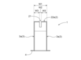
- FIG. 1 is a front view of a hot air nozzle according to an embodiment
- FIG. It is a top view of the hot-air nozzle which concerns on embodiment.
- 4 is a cross-sectional view taken along line IV-IV of FIG. 3
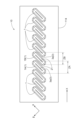
- FIG. It is a top view of a nozzle row concerning an embodiment.
- It is a schematic diagram which shows distribution of the hot air discharged from the nozzle row which concerns on embodiment.
- It is a sectional view of a drying oven concerning a modification.
- FIG. 1 An embodiment of a hot air nozzle and a drying furnace according to the present invention will be described with reference to the drawings.
- an embodiment of the present invention will be described by taking as an example a drying furnace 100 used in a painting facility for a vehicle body B of an automobile and a hot air nozzle 1 provided in the drying furnace 100.
- FIG. 1 An embodiment of a hot air nozzle and a drying furnace according to the present invention will be described with reference to the drawings.
- FIG. 1 An embodiment of a hot air nozzle and a drying furnace according to the present invention will be described with reference to the drawings.
- FIG. 1 An embodiment of a hot air nozzle and a drying furnace according to the present invention will be described with reference to the drawings.
- a drying furnace 100 according to this embodiment is used as a device for drying a vehicle body B in a painting facility.
- the temperature of the vehicle body B accommodated in the internal space S rises, thereby drying the paint adhering to the vehicle body B ( Figure 1).
- the vehicle body B is conveyed by the conveyor 120 and advances in the drying furnace 100 in the longitudinal direction of the internal space S (the X-axis direction in FIG. 1).
- the hot air nozzle 1 includes a tip surface 2 having a discharge port 21 and a side surface 3 extending between the tip surface 2 and the base end 4 (FIGS. 2 to 4).
- the hot air nozzle 1 extends from the wall surface (inclined surface 114) of the drying furnace 100 toward the internal space S, and the base end 4 is arranged on the wall surface.
- the proximal end 4 is connected to an air supply duct.
- the tip surface 2 is rectangular in the top view (Fig. 3), and therefore the longitudinal direction ⁇ and the transverse direction ⁇ can be distinguished.
- a side surface 3a on the long side (longitudinal direction ⁇ ) of the distal end surface 2 and a side surface 3b on the short side (lateral direction ⁇ ) of the distal end surface 2 can be distinguished.
- a central portion 22 in the longitudinal direction ⁇ of the distal end surface 2 is provided so as to protrude from end portions 23 located at both ends in the longitudinal direction ⁇ (Fig. 2). More specifically, the distal end surface 2 is provided as a curved surface that is continuously curved over the ends 23 on both sides.
- the curved shape of the tip surface 2 corresponds to a fan-shaped arc portion with a radius of 97 mm and a central angle of 84°, and the apex 22a of the central portion 22 protrudes from the end portion 23 by 25 mm.
- the width W1 of the distal end surface 2 in the cross section (FIG. 4) along the lateral direction ⁇ is 35 mm.
- the hot air nozzle 1 can sufficiently serve as a pressure header.
- the width W1 of the tip surface 2 is sufficiently larger than the width W2 of the discharge port 21, which will be described later, the speed of the hot air discharged from the hot air nozzle 1 tends to be uniform.
- the width W1 of the distal end surface 2 is excessively large, the attraction effect may be impaired, so the upper limit is set to the preferred range as described above.
- the discharge port 21 is provided as a rectangular slit opening along the longitudinal direction ⁇ at the center of the distal end surface 2 in the lateral direction ⁇ (FIGS. 2 to 4).
- the width W2 of the ejection port 21 is 5 mm, which is 14% of the width W1 (35 mm) of the tip surface 2, in the cross section (FIG. 4) along the lateral direction ⁇ .
- the width W2 of the discharge port 21 when the width W2 of the discharge port 21 is 5 mm or more, the opening of the discharge port 21 can be sufficiently secured, and the pressure loss of the discharged hot air (heated air) can be suppressed, which is preferable. Further, when the width W2 of the discharge port 21 is 20 mm or less, the wind velocity of the discharged hot air easily reaches a level (for example, 15 to 25 m/s) having a sufficient air induction effect, which is preferable.
- the width W3 of the substantial portion of the distal end face 2 sandwiching the discharge port 21 in the cross section (FIG. 4) along the lateral direction ⁇ is secured on both sides by 15 mm.
- the width W3 of the substantial portion adjacent to the ejection port 21 is secured to be 5 mm or more in this manner, a swirling flow is likely to occur around the ejection port 21, which facilitates agitation of the surrounding air, which is preferable.
- the substantial portion and the direction in which the hot air is discharged are orthogonal, and therefore it is preferable that the tip surface 2 and the side surface 3 are orthogonal.
- the width of the substantial portion of the distal end surface 2 sandwiching the ejection port 21 may not be equal on both sides of the ejection port.
- the discharge port 21 is provided along the shape in which the tip surface 2 protrudes (curves).
- the length L of the discharge port 21 along the curved surface of the distal end surface 2 is 100 mm. Since the outlet 21 is provided along the shape in which the tip end surface 2 protrudes (curves), the hot air discharged from the outlet 21 is directed not only in the direction in which the hot air nozzle extends, but also in the straight direction. , the ink is also discharged in directions extending leftward and rightward from the straight direction. That is, according to the hot air nozzle 1 according to the present embodiment, hot air can be discharged radially extending in the longitudinal direction ⁇ . It should be noted that if there is a substantial portion of the tip end surface 2 sandwiching the discharge port 21 in the cross section along the longitudinal direction ⁇ , the hot air is particularly likely to be radial, which is preferable.
- the drying oven 100 includes a booth 110, a conveyor 120 (which is an example of a support section) capable of supporting a vehicle body B (which is an example of a work), and a plurality of hot air nozzles 1 (FIG. 1).
- the booth 110 includes a bottom surface 111 that defines the bottom of the booth 110, two side walls 112 that define the side surfaces of the booth 110, a top surface 113 that defines the top surface of the booth 110, and the bottom surface 111 and the side walls 112. There are two ramps 114 extending therebetween.
- the inclined surface 114 is inclined at 45° with respect to the horizontal direction (XY plane direction in FIG. 1).
- a tunnel-shaped internal space S is formed inside the booth 110 by the bottom surface 111 , the side wall surface 112 , the top surface 113 , and the inclined surface 114 .
- the conveyor 120 extends upward from the bottom surface 111 and is configured to support the vehicle body B and transport the vehicle body B in the longitudinal direction of the internal space S (the X-axis direction in FIG. 1).
- the hot air nozzles 1 form a nozzle row 10 in which a plurality of hot air nozzles 1 (10 in this embodiment) are arranged in a straight line (Fig. 5). In each nozzle row 10, the adjacent hot air nozzles 1 are spaced apart from each other with the side surfaces 3a (the long side of the tip surface 2) facing each other.
- each nozzle row 10 is along the longitudinal direction of the inclined surface 114 (the X-axis direction in FIG. 1).
- Each of the plurality of hot air nozzles 1 forms an angle of 45° between the longitudinal direction ⁇ of the hot air nozzle 1 and the extending direction of the nozzle row 10 to which the hot air nozzle 1 belongs (the X-axis direction in FIG. 1). is provided as follows.
- the existence range ZA of a certain hot air nozzle 1A along the extending direction of the nozzle row 10 partially overlaps the existence range ZB along the extending direction of the hot air nozzle 1B adjacent to the hot air nozzle 1A. (Fig. 5).
- the hot air discharged from the adjacent hot air nozzles 1 overlaps the range D, so that the hot air discharged from the hot air nozzles 1 can be continuously supplied to the vehicle body while the vehicle body B is conveyed along the longitudinal direction of the internal space S.
- a state corresponding to B can be realized (FIG. 6).
- the longitudinal direction ⁇ of the hot air nozzle 1 and the extending direction of the nozzle row 10 to which the hot air nozzle 1 belongs are greater than 0° and less than 90°.
- Each hot air nozzle 1 extends vertically from the inclined surface 114 toward the internal space S. Since the inclined surface 114 is provided at an angle of 45° with respect to the horizontal direction (XY plane direction in FIG. 1), each hot air nozzle 1 is provided at an angle of 45° with respect to the horizontal direction.
- the hot air discharged from the hot air nozzle 1 hits the vehicle body B supported by the conveyor 120 from the diagonally downward direction of the vehicle body B.
- each nozzle row 10 is arranged on each of the two inclined surfaces 114, so that hot air can be applied to both the left and right sides of the vehicle body B from an obliquely downward direction.
- the temperature of the lower part of the vehicle body B bottom part, door lower part, etc.
- this configuration makes it possible to intensively apply hot air to the lower part, thereby facilitating raising the temperature of the lower part.
- baffle plates 115 (115A, 115B, 115C) extending inside the booth 110 are provided.
- the baffle plate 115A extends downward from the top surface 113
- the baffle plates 115B and 115C extend upward from the bottom surface 111, respectively.
- the extension length of baffle plate 115A is 350 mm
- the extension length of baffle plate 115B and baffle plate 115C is 250 mm.
- a swirling flow (a flow of air flowing clockwise or counterclockwise along the YZ plane in FIG. 7) may occur in the internal space S due to the hot air being discharged from the hot air nozzle 1 .
- the baffle plate 115 is provided to block the flow of air flowing in the direction of the cross section of the internal space S (the YZ plane in FIG. 7), thereby suppressing the swirling flow.
- baffle plate 115 when the baffle plate 115 is provided, it is not necessary to provide the three baffle plates 115 (115A, 115B, 115C) as in this modification, and at least one of the cross sections of the internal space S (YZ plane in FIG. 7) It is sufficient if the air flow is interrupted at some point. For example, only one baffle plate 115A extending from the top surface 113 may be provided.
- the distal end surface 2 is provided as a curved surface that is continuously curved over the ends 23 on both sides.
- the distal end surface according to the present invention is not limited to a curved surface as long as the central portion in the longitudinal direction protrudes from both ends in the longitudinal direction.
- the tip surface may be provided by combining a plurality of planes.
- the shape of the tip surface in the front view (the shape of the tip surface in the viewpoint corresponding to FIG. 2) can be a part of a polygon.
- the ejection port in order to provide the ejection port along the shape of the protruding end surface, it is preferable that the ejection port is provided across at least one vertex of the polygon. That is, it is sufficient that the discharge port is provided in a shape capable of discharging hot air radially extending in the longitudinal direction.
- the shape of the distal end face is not limited as long as the shape is distinguishable between the longitudinal direction and the lateral direction, and may be, for example, an ellipse or a polygon.
- the configuration in which the ejection port 21 is provided as a rectangular slit has been described as an example.
- the shape and arrangement of the discharge port in the present invention are limited as long as the discharge port is provided along the shape in which the tip surface protrudes (that is, it is provided in a shape that can discharge hot air radially extending in the longitudinal direction).
- the ejection port may have, for example, an elliptical or polygonal shape, or may have a configuration in which a plurality of small openings are arranged along a shape in which the tip surface protrudes.
- each sub-aperture may be of any shape, such as circular, elliptical, or polygonal.
- the longitudinal direction ⁇ of the hot air nozzle 1 and the extending direction of the nozzle row 10 to which the hot air nozzle 1 belongs are provided so as to form an angle of 45°. It has been explained that the angle is preferably larger than 0° and smaller than 90°. However, in the present invention, the angle formed by the hot air nozzle and the extending direction of the nozzle row to which the hot air nozzle belongs is not particularly limited.
- the existence range ZA of the hot air nozzle 1A along the extending direction of the nozzle row 10 is partially combined with the existence range ZB along the extending direction of the hot air nozzle 1B adjacent to the hot air nozzle 1A.
- An overlapping configuration has been described as an example. However, in the present invention such duplication need not exist.
- the configuration in which the hot air nozzle 1 (nozzle row 10) is provided on the inclined surface 114 has been described as an example.
- the position where the hot air nozzle is provided is not limited.
- the inclination with respect to the horizontal direction is not limited to 45° in the above example, and can be appropriately determined according to the workpiece. Specifically, it is possible to consider the placement of a portion of the work to which the hot air should be applied intensively and a portion to which the hot air should not be applied much.
- the drying furnace 100 as a device for drying the vehicle body B has been described as an example.
- the work to be dried is not limited.
- the configuration in which the drying oven 100 includes the conveyor 120 and the vehicle body B is conveyed by the conveyor 120 has been described as an example.
- the supporting portion is not limited as long as it can support the work. That is, the supporting part is not limited to a movable type like the conveyor 120 in the above embodiment, and may be a fixed type.
- the drying oven 100 including the hot air nozzle 1 according to the above embodiment has been described as an example.
- the hot air nozzle provided in the drying furnace according to the present invention is not limited as long as it is the hot air nozzle according to the present invention. That is, the present invention can be the use of the hot air nozzle according to the present invention in a drying oven.
- the present invention can be used, for example, in a drying oven for drying workpieces and a hot air nozzle installed in the drying oven.
- hot air nozzle 2 tip surface 21: discharge port 22: central portion of tip surface 22a: apex of central portion of tip surface 23: edge of tip surface 3: side surface 3a: side surface on long side of tip surface 3b: 4: base end 10: nozzle row 100: drying oven 110: booth 111: bottom surface 112: side wall surface 113: top surface 114: inclined surface 115: baffle plate 120: conveyor B: car body S: Interior space of drying furnace ZA, ZB: Existence range of hot air nozzle D: Overlapping range of hot air ⁇ : Longitudinal direction of hot air nozzle ⁇ : Short direction of hot air nozzle
Landscapes
- Engineering & Computer Science (AREA)
- Mechanical Engineering (AREA)
- General Engineering & Computer Science (AREA)
- Life Sciences & Earth Sciences (AREA)
- Chemical & Material Sciences (AREA)
- Combustion & Propulsion (AREA)
- Sustainable Development (AREA)
- Microbiology (AREA)
- Drying Of Solid Materials (AREA)
- Nozzles (AREA)
Priority Applications (5)
| Application Number | Priority Date | Filing Date | Title |
|---|---|---|---|
| JP2023516503A JP7546765B2 (ja) | 2021-12-28 | 2021-12-28 | 熱風ノズルおよび乾燥炉 |
| KR1020237008229A KR102773682B1 (ko) | 2021-12-28 | 2021-12-28 | 열풍 노즐 열 및 건조로 |
| CN202180062113.2A CN116670455A (zh) | 2021-12-28 | 2021-12-28 | 热风喷嘴和干燥炉 |
| PCT/JP2021/048860 WO2023127120A1 (ja) | 2021-12-28 | 2021-12-28 | 熱風ノズルおよび乾燥炉 |
| US18/026,486 US20240295360A1 (en) | 2021-12-28 | 2021-12-28 | Hot Air Nozzle and Drying Oven |
Applications Claiming Priority (1)
| Application Number | Priority Date | Filing Date | Title |
|---|---|---|---|
| PCT/JP2021/048860 WO2023127120A1 (ja) | 2021-12-28 | 2021-12-28 | 熱風ノズルおよび乾燥炉 |
Publications (1)
| Publication Number | Publication Date |
|---|---|
| WO2023127120A1 true WO2023127120A1 (ja) | 2023-07-06 |
Family
ID=86998400
Family Applications (1)
| Application Number | Title | Priority Date | Filing Date |
|---|---|---|---|
| PCT/JP2021/048860 Ceased WO2023127120A1 (ja) | 2021-12-28 | 2021-12-28 | 熱風ノズルおよび乾燥炉 |
Country Status (5)
| Country | Link |
|---|---|
| US (1) | US20240295360A1 (https=) |
| JP (1) | JP7546765B2 (https=) |
| KR (1) | KR102773682B1 (https=) |
| CN (1) | CN116670455A (https=) |
| WO (1) | WO2023127120A1 (https=) |
Citations (6)
| Publication number | Priority date | Publication date | Assignee | Title |
|---|---|---|---|---|
| JPH0999263A (ja) | 1995-10-04 | 1997-04-15 | Taikisha Ltd | 塗装乾燥炉 |
| JPH11188303A (ja) | 1997-12-26 | 1999-07-13 | Trinity Ind Corp | 乾燥炉 |
| JPH11290751A (ja) | 1998-04-13 | 1999-10-26 | Taikisha Ltd | 熱風式乾燥炉 |
| JP2000070822A (ja) * | 1998-09-01 | 2000-03-07 | Nissan Motor Co Ltd | 塗装乾燥炉 |
| JP2004184009A (ja) * | 2002-12-05 | 2004-07-02 | Fuji Photo Film Co Ltd | 乾燥装置 |
| JP2018155463A (ja) * | 2017-03-21 | 2018-10-04 | トリニティ工業株式会社 | ノズル及び乾燥システム |
Family Cites Families (8)
| Publication number | Priority date | Publication date | Assignee | Title |
|---|---|---|---|---|
| JPH0537191Y2 (https=) * | 1986-09-04 | 1993-09-20 | ||
| JPH0536660A (ja) * | 1991-07-30 | 1993-02-12 | Tokyo Electron Ltd | 基板乾燥装置 |
| JPH05172462A (ja) * | 1991-12-13 | 1993-07-09 | Wakayama Tekko Kk | 熱風布帛乾燥装置 |
| JP4044686B2 (ja) * | 1997-11-21 | 2008-02-06 | 本田技研工業株式会社 | 乾燥炉 |
| CN101598492B (zh) * | 2009-04-30 | 2010-12-29 | 长沙楚天科技有限公司 | 用于洗瓶机的除积水装置 |
| CN204329520U (zh) * | 2014-11-17 | 2015-05-13 | 江阴市长泾花园毛纺织有限公司 | 一种十字绕筒纺织品双向烘干设备 |
| DE102017101336A1 (de) * | 2017-01-25 | 2018-07-26 | Abb Schweiz Ag | Sprühapplikator |
| CN209445730U (zh) * | 2018-09-12 | 2019-09-27 | 广东晟启环保产业有限公司 | 热泵除湿干燥箱体 |
-
2021
- 2021-12-28 CN CN202180062113.2A patent/CN116670455A/zh active Pending
- 2021-12-28 KR KR1020237008229A patent/KR102773682B1/ko active Active
- 2021-12-28 WO PCT/JP2021/048860 patent/WO2023127120A1/ja not_active Ceased
- 2021-12-28 JP JP2023516503A patent/JP7546765B2/ja active Active
- 2021-12-28 US US18/026,486 patent/US20240295360A1/en active Pending
Patent Citations (7)
| Publication number | Priority date | Publication date | Assignee | Title |
|---|---|---|---|---|
| JPH0999263A (ja) | 1995-10-04 | 1997-04-15 | Taikisha Ltd | 塗装乾燥炉 |
| US5823767A (en) | 1995-10-04 | 1998-10-20 | Taikisha Ltd | Paint drying furnace |
| JPH11188303A (ja) | 1997-12-26 | 1999-07-13 | Trinity Ind Corp | 乾燥炉 |
| JPH11290751A (ja) | 1998-04-13 | 1999-10-26 | Taikisha Ltd | 熱風式乾燥炉 |
| JP2000070822A (ja) * | 1998-09-01 | 2000-03-07 | Nissan Motor Co Ltd | 塗装乾燥炉 |
| JP2004184009A (ja) * | 2002-12-05 | 2004-07-02 | Fuji Photo Film Co Ltd | 乾燥装置 |
| JP2018155463A (ja) * | 2017-03-21 | 2018-10-04 | トリニティ工業株式会社 | ノズル及び乾燥システム |
Also Published As
| Publication number | Publication date |
|---|---|
| KR20230106148A (ko) | 2023-07-12 |
| CN116670455A (zh) | 2023-08-29 |
| KR102773682B1 (ko) | 2025-02-25 |
| JPWO2023127120A1 (https=) | 2023-07-06 |
| JP7546765B2 (ja) | 2024-09-06 |
| US20240295360A1 (en) | 2024-09-05 |
Similar Documents
| Publication | Publication Date | Title |
|---|---|---|
| JP3576973B2 (ja) | ヤンキーシリンダーをカバーするフードの乾燥能力を改良するための方法および装置 | |
| JP2020016389A (ja) | インク乾燥装置 | |
| WO2023127120A1 (ja) | 熱風ノズルおよび乾燥炉 | |
| KR20170021074A (ko) | 건조 장치 | |
| JP7499578B2 (ja) | 乾燥炉 | |
| JP2005058870A (ja) | 塗装乾燥炉 | |
| US7264467B1 (en) | Convection oven with turbo flow air nozzle to increase air flow and method of using same | |
| JP4620327B2 (ja) | 流体を薄い要素の少なくとも表面に吹きつける装置及び組合された吹きつけユニット | |
| KR101769059B1 (ko) | 폐열 재활용 소둔로 시스템 | |
| JP3657111B2 (ja) | 熱風式乾燥炉 | |
| CN213146954U (zh) | 可实现均匀加热的导风板、可实现均匀加热的风室 | |
| CN212315922U (zh) | 一种玻璃钢化炉对流加热结构及玻璃钢化炉 | |
| JPS6254188B2 (https=) | ||
| KR200175927Y1 (ko) | 텐터기의 열풍 공급시스템의 버너 열기 배출구조 | |
| JP3128495B2 (ja) | 外側熱風・内側排風式の穀粒乾燥機における熱風生成装置 | |
| CN208736065U (zh) | 一种立式干燥机 | |
| JP2004278830A (ja) | 乾燥炉 | |
| JPH031090Y2 (https=) | ||
| JPH1128409A (ja) | 塗装用乾燥炉 | |
| CN224080678U (zh) | 一种表干炉新型热风循环系统 | |
| JPS607814Y2 (ja) | 塗装用焼付炉 | |
| JPH053890U (ja) | 赤外線乾燥炉 | |
| JPH0319961Y2 (https=) | ||
| CN213708122U (zh) | 气流辅助加工设备及玻璃生产装置 | |
| JP2606029B2 (ja) | 熱風乾燥方法 |
Legal Events
| Date | Code | Title | Description |
|---|---|---|---|
| WWE | Wipo information: entry into national phase |
Ref document number: 202347015763 Country of ref document: IN |
|
| WWE | Wipo information: entry into national phase |
Ref document number: 202180062113.2 Country of ref document: CN |
|
| WWE | Wipo information: entry into national phase |
Ref document number: 2023516503 Country of ref document: JP |
|
| WWE | Wipo information: entry into national phase |
Ref document number: 18026486 Country of ref document: US |
|
| ENP | Entry into the national phase |
Ref document number: 2021955261 Country of ref document: EP Effective date: 20230308 |
|
| NENP | Non-entry into the national phase |
Ref country code: DE |
|
| WWP | Wipo information: published in national office |
Ref document number: 202347015763 Country of ref document: IN |