WO2023089787A1 - 電動機制御方法及び電動機制御装置 - Google Patents
電動機制御方法及び電動機制御装置 Download PDFInfo
- Publication number
- WO2023089787A1 WO2023089787A1 PCT/JP2021/042656 JP2021042656W WO2023089787A1 WO 2023089787 A1 WO2023089787 A1 WO 2023089787A1 JP 2021042656 W JP2021042656 W JP 2021042656W WO 2023089787 A1 WO2023089787 A1 WO 2023089787A1
- Authority
- WO
- WIPO (PCT)
- Prior art keywords
- torque
- command value
- electric motor
- vibration
- voltage
- Prior art date
- Legal status (The legal status is an assumption and is not a legal conclusion. Google has not performed a legal analysis and makes no representation as to the accuracy of the status listed.)
- Ceased
Links
Images





Classifications
-
- B—PERFORMING OPERATIONS; TRANSPORTING
- B60—VEHICLES IN GENERAL
- B60L—PROPULSION OF ELECTRICALLY-PROPELLED VEHICLES; SUPPLYING ELECTRIC POWER FOR AUXILIARY EQUIPMENT OF ELECTRICALLY-PROPELLED VEHICLES; ELECTRODYNAMIC BRAKE SYSTEMS FOR VEHICLES IN GENERAL; MAGNETIC SUSPENSION OR LEVITATION FOR VEHICLES; MONITORING OPERATING VARIABLES OF ELECTRICALLY-PROPELLED VEHICLES; ELECTRIC SAFETY DEVICES FOR ELECTRICALLY-PROPELLED VEHICLES
- B60L15/00—Methods, circuits, or devices for controlling the traction-motor speed of electrically-propelled vehicles
- B60L15/20—Methods, circuits, or devices for controlling the traction-motor speed of electrically-propelled vehicles for control of the vehicle or its driving motor to achieve a desired performance, e.g. speed, torque, programmed variation of speed
-
- H—ELECTRICITY
- H02—GENERATION; CONVERSION OR DISTRIBUTION OF ELECTRIC POWER
- H02P—CONTROL OR REGULATION OF ELECTRIC MOTORS, ELECTRIC GENERATORS OR DYNAMO-ELECTRIC CONVERTERS; CONTROLLING TRANSFORMERS, REACTORS OR CHOKE COILS
- H02P21/00—Arrangements or methods for the control of electric machines by vector control, e.g. by control of field orientation
- H02P21/05—Arrangements or methods for the control of electric machines by vector control, e.g. by control of field orientation specially adapted for damping motor oscillations, e.g. for reducing hunting
-
- H—ELECTRICITY
- H02—GENERATION; CONVERSION OR DISTRIBUTION OF ELECTRIC POWER
- H02P—CONTROL OR REGULATION OF ELECTRIC MOTORS, ELECTRIC GENERATORS OR DYNAMO-ELECTRIC CONVERTERS; CONTROLLING TRANSFORMERS, REACTORS OR CHOKE COILS
- H02P21/00—Arrangements or methods for the control of electric machines by vector control, e.g. by control of field orientation
- H02P21/14—Estimation or adaptation of machine parameters, e.g. flux, current or voltage
- H02P21/18—Estimation of position or speed
-
- H—ELECTRICITY
- H02—GENERATION; CONVERSION OR DISTRIBUTION OF ELECTRIC POWER
- H02P—CONTROL OR REGULATION OF ELECTRIC MOTORS, ELECTRIC GENERATORS OR DYNAMO-ELECTRIC CONVERTERS; CONTROLLING TRANSFORMERS, REACTORS OR CHOKE COILS
- H02P27/00—Arrangements or methods for the control of AC motors characterised by the kind of supply voltage
- H02P27/04—Arrangements or methods for the control of AC motors characterised by the kind of supply voltage using variable-frequency supply voltage, e.g. inverter or converter supply voltage
- H02P27/06—Arrangements or methods for the control of AC motors characterised by the kind of supply voltage using variable-frequency supply voltage, e.g. inverter or converter supply voltage using DC to AC converters or inverters
- H02P27/08—Arrangements or methods for the control of AC motors characterised by the kind of supply voltage using variable-frequency supply voltage, e.g. inverter or converter supply voltage using DC to AC converters or inverters with pulse width modulation
- H02P27/12—Arrangements or methods for the control of AC motors characterised by the kind of supply voltage using variable-frequency supply voltage, e.g. inverter or converter supply voltage using DC to AC converters or inverters with pulse width modulation pulsing by guiding the flux vector, current vector or voltage vector on a circle or a closed curve, e.g. for direct torque control
-
- H—ELECTRICITY
- H02—GENERATION; CONVERSION OR DISTRIBUTION OF ELECTRIC POWER
- H02P—CONTROL OR REGULATION OF ELECTRIC MOTORS, ELECTRIC GENERATORS OR DYNAMO-ELECTRIC CONVERTERS; CONTROLLING TRANSFORMERS, REACTORS OR CHOKE COILS
- H02P29/00—Arrangements for regulating or controlling electric motors, appropriate for both AC and DC motors
- H02P29/02—Providing protection against overload without automatic interruption of supply
- H02P29/032—Preventing damage to the motor, e.g. setting individual current limits for different drive conditions
-
- H—ELECTRICITY
- H02—GENERATION; CONVERSION OR DISTRIBUTION OF ELECTRIC POWER
- H02P—CONTROL OR REGULATION OF ELECTRIC MOTORS, ELECTRIC GENERATORS OR DYNAMO-ELECTRIC CONVERTERS; CONTROLLING TRANSFORMERS, REACTORS OR CHOKE COILS
- H02P6/00—Arrangements for controlling synchronous motors or other dynamo-electric motors using electronic commutation dependent on the rotor position; Electronic commutators therefor
- H02P6/10—Arrangements for controlling torque ripple, e.g. providing reduced torque ripple
Definitions
- the present invention relates to a motor control method and a motor control device.
- JP2012-75257A proposes an electric motor control method for executing damping control for suppressing vibration caused by torsional vibration characteristics of a drive transmission system in a vehicle. Furthermore, in this electric motor control method, from the viewpoint of suppressing abnormal noise generated in the gears of the speed reducer due to repeated positive and negative reversal of the torque command, the above-described vibration damping is performed in a specific motor operating region where the abnormal noise may occur. A control is employed that limits the damping function associated with the control.
- an object of the present invention is to provide a motor control method and a motor control device capable of suppressing the torsional vibration of the drive transmission system even under the restriction of the damping function for suppressing the torsional vibration.
- an electric motor control method for controlling an electric motor based on a first torque command value corresponding to the required output of the electric motor.
- This electric motor control method includes a damping step of calculating a second torque command value by correcting the first torque command value with a vibration compensating torque, a limiting step of limiting the vibration compensating torque based on a suggested limit request amount, a restriction level determination step of determining a restriction level representing the degree of restriction on the vibration compensation torque; and a torque control step of feeding back a torque indication amount indicating the motor torque to the second torque command value to calculate the voltage command value.
- the vibration compensating torque is a torque correction value for suppressing vibration of the motor rotation speed.
- the restriction request suggestion amount suggests a situation in which suppression of vibration of the motor rotation speed should be restricted.
- the voltage command value is a command value of the voltage supplied to the motor from a predetermined power source. Then, in the torque control process, the feedback gain of the suggested torque amount is determined with reference to the limit level.
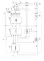
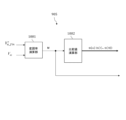
- FIG. 1 is a block diagram illustrating the configuration of a motor control device that executes a motor control method according to each embodiment of the present invention.
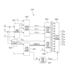
- FIG. 2 is a block diagram illustrating the configuration of the damping control section.
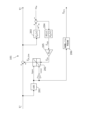
- FIG. 3 is a diagram illustrating a dynamic system model that provides an equation of motion for a torsional vibration system.
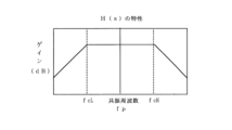
- FIG. 4 is a graph showing filter characteristics of the bandpass filter H(s).
- FIG. 5 is a block diagram for explaining the configuration of the torque control section.
- FIG. 6 is a block diagram for explaining the configuration of the current vector control section.
- FIG. 7 is a block diagram illustrating the configuration of the torque compensator.
- FIG. 8 is a block diagram for explaining the configuration of the voltage phase control section.
- FIG. 1 is a block diagram illustrating the configuration of a motor control device that executes a motor control method according to each embodiment of the present invention.
- FIG. 2 is a block diagram illustrating the configuration of the damping control section.
- FIG. 3 is
- FIG. 9 is a block diagram for explaining the configuration of the PWM controller.
- FIG. 10 is a block diagram for explaining the configuration of the synchronous PWM controller.
- FIG. 11 is a timing chart illustrating processing in asynchronous PWM control and synchronous PWM control.
- FIG. 12 is a flow chart for explaining each process in the damping control section, torque control section, and PWM control section.
- FIG. 13 is a block diagram illustrating the configuration of a damping control section according to another embodiment.
- FIG. 1 is a block diagram illustrating a motor control device 10 that executes a motor control method.
- the motor control device 10 drives the motor 106 with electric power supplied from the battery 113 and controls its operating state.
- the electric motor control device 10 is mounted, for example, in a vehicle such as an electric vehicle or a hybrid vehicle that uses the motor 106 as a drive source.
- the battery 113 is a secondary battery such as a lithium ion battery that functions as a power supply source for the motor 106 and other parts of the vehicle.
- the battery 113 is a DC power supply.
- the voltage output by the battery 113 (hereinafter also referred to as “DC voltage V dc ”) is detected by the voltage sensor 112 .
- the motor 106 is composed of, for example, an IPM (Interior Permanent Magnet) type three-phase synchronous electric motor.
- the motor 106 (more specifically, the rotor of the motor 106) is connected to the driving wheels via a driving force transmission system of the vehicle such as an output shaft, gears, and drive shafts (not shown).
- the motor control device 10 mainly has a damping control section 101, a torque control section 102, a PWM (Pulse Width Modulation) control section 103, a speed calculation section 110, and a coordinate conversion section 111.
- a damping control section 101 mainly has a damping control section 101, a torque control section 102, a PWM (Pulse Width Modulation) control section 103, a speed calculation section 110, and a coordinate conversion section 111.
- PWM Pulse Width Modulation
- the damping control unit 101 performs damping for suppressing vibrations caused by the driving force transmission system (vibration of the motor rotation speed) based on the first torque command value T * 1 and the mechanical angular velocity ⁇ m of the motor 106.
- a second torque command value T * 2 is obtained by executing a control calculation.
- the first torque command value T * 1 is a basic torque command value determined from the required output of the motor 106 .
- the required output for the motor 106 is determined according to the operation of the vehicle by the driver (operation on the accelerator pedal) or the required driving force based on the command of a higher controller (not shown) such as a predetermined automatic driving control device.
- damping control unit 101 Furthermore, the damping control unit 101 generates a limit level signal SH/L as a flag indicating whether or not a certain limit or more is imposed on the damping control calculation. Then, damping control section 101 outputs second torque command value T * 2 and limit level signal SH /L to torque control section 102 . Details of the processing in the damping control unit 101 will be described later.
- Torque control unit 102 inputs DC voltage Vdc , limit level signal SH /L , second torque command value T * 2 , electrical angular velocity ⁇ e of motor 106, d -axis current id, and q -axis current iq. , the command values of the voltage to be supplied to the motor 106 (d-axis voltage command value v * d and q-axis voltage command value vq ) are calculated. Torque control unit 102 then outputs the calculated d-axis voltage command value v * d and q-axis voltage command value v * q to PWM control unit 103 . Details of the processing in the torque control unit 102 will be described later.
- x d or q
- the d-axis current id and the q-axis current iq are collectively referred to as "dq-axis current ix ".
- PWM control unit 103 receives DC voltage V dc , voltage command value v * x , and electrical angle ⁇ of motor 106 as input, and generates drive signals D * uu to D * wl for driving switching elements of inverter 104 . do. Then, PWM control section 103 outputs the generated drive signals D * uu to D * wl to inverter 104 . Details of processing in the PWM control unit 103 will be described later.
- Inverter 104 includes a plurality of semiconductor switching elements and a drive circuit (not shown) that drives these switching elements.
- the inverter 104 drives each switching element according to the drive signals D * uu to D * wl .
- the DC voltage V dc is converted into three-phase AC voltages (v u , v v , v w ) and supplied to the motor 106 . That is, motor 106 is driven to output actual torque corresponding to desired torque command value T * .
- the current sensor 105 is composed of a plurality of individual sensors that detect each phase component of the three-phase alternating current (i u , iv , i w ) output by the inverter 104 .
- FIG. 1 shows an example in which the current sensor 105 is composed of two separate sensors that respectively detect the u-phase current iu and the v-phase current iv .
- the remaining w-phase current iw can be determined from the u-phase current iu and the v-phase current iv using the fact that the sum of the three-phase components is zero.
- the current sensors 105 may be composed of individual sensors provided for all three phases. The current sensor 105 then outputs the detected current value of each phase to the coordinate transformation unit 111 .
- the resolver 107 functions as a rotor position detector that detects the rotor position of the motor 106 .
- resolver 107 transmits and receives excitation/modulation signals to and from RDIC (resolver/digital conversion circuit) 108 .
- the RDIC 108 generates an ABZ signal (digital angle information of the motor 106) consisting of up-down counter pulses A and B and an origin signal pulse Z based on the excitation/modulation signal.
- the RDIC 108 outputs the generated ABZ signal to the ABZ counter 109 .
- the ABZ counter 109 calculates the electrical angle ⁇ based on the ABZ signal. Then, the ABZ counter 109 outputs the calculated electrical angle ⁇ to the PWM control section 103 , the speed calculation section 110 and the coordinate conversion section 111 .
- a velocity calculator 110 calculates an electrical angular velocity ⁇ e and a mechanical angular velocity ⁇ m of the motor 106 from the amount of change in the electrical angle ⁇ per time. Then, the speed calculation unit 110 outputs the calculated electrical angular speed ⁇ e to the torque control unit 102 and the calculated mechanical angular speed ⁇ m to the damping control unit 101 .
- the coordinate conversion unit 111 converts the three-phase alternating current (i u , iv , i w ) detected by the current sensor 105 into the dq-axis current ix based on the following equation (1) using the electrical angle ⁇ . do.
- the dq-axis current i x corresponding to the current detection value in the dq-axis coordinate system is determined by equation (1).
- Coordinate transformation unit 111 then outputs the obtained dq-axis current ix to torque control unit 102 .
- the motor control device 10 includes a central processing unit (CPU), a read-only memory (ROM), a random access memory (RAM), and an input/output interface (I/O interface), and can execute each configuration described above. implemented by a computer programmed to It is also possible to configure the motor control device 10 with a plurality of pieces of computer hardware that execute each process in a distributed manner.
- CPU central processing unit
- ROM read-only memory
- RAM random access memory
- I/O interface input/output interface
- FIG. 2 is a block diagram for explaining the configuration of the damping control section 101.
- the damping control section 101 includes an absolute value processing section 201 , a limiter 202 , a mechanical angular velocity estimating section 203 , a vibration torque estimating section 204 and a gain section 205 .
- the mechanical angular velocity estimating section 203, the vibration torque estimating section 204, and the gain section 205 mainly function as a configuration for obtaining the vibration compensating torque Tfb .
- the vibration compensation torque Tfb is a torque correction value for the first torque command value T * 1 .
- the vibration compensating torque T fb is determined from the first torque command value T * 1 corresponding to the required output of the motor 106 so as to eliminate the vibration of the motor rotation speed caused by the torsional vibration of the driving force transmission system.
- the mechanical angular velocity estimator 203 applies a transmission characteristic G p (s) obtained from a vehicle transmission system model, which will be described later, to the feedback value of the second torque command value T * 2 to obtain the estimated mechanical angular velocity ⁇ m Ask for Then, the vibration torque estimator 204 receives the deviation between the estimated mechanical angular velocity ⁇ m and the mechanical angular velocity ⁇ m equivalent to the above-described detection value, and is composed of a transmission characteristic G p (s) and a bandpass filter H(s). A transfer function is applied to obtain the vibration torque T vib . Further, gain section 205 obtains vibration compensation torque T fb by applying vibration damping gain K fb (0 ⁇ K fb ⁇ 1) to vibration torque T vib and outputs it to limiter 202 .
- G p (s) obtained from a vehicle transmission system model, which will be described later
- the absolute value processing unit 201 and the limiter 202 function as a configuration that determines the limit vibration compensation torque Tfb_lim .
- the limit vibration compensation torque Tfb_lim is a value obtained by limiting the vibration compensation torque Tfb under a predetermined condition determined in consideration of suppression of abnormal noise caused by gear backlash.
- the absolute value processing unit 201 performs absolute value processing on the first torque command value T * 1 , and sets the upper limit value and the lower limit value of the absolute value to the upper limit value and the lower limit value of the limiter 202 (hereinafter referred to as These are collectively referred to as “upper and lower limits”). That is, in the present embodiment, the first torque command value T * 1 suggests a situation in which suppression of torsional vibration in the driving force transmission system should be limited (in particular, a situation in which abnormal noise caused by gear backlash may occur).
- the limiter 202 obtains the limit vibration compensation torque Tfb_lim by performing limit processing on the vibration compensation torque Tfb based on the upper and lower limits defined by the absolute value processing unit 201 .
- the limit vibration compensating torque Tfb_lim also becomes zero. Therefore, in this case, it is possible to suppress the occurrence of gear noise and the deterioration of control stability due to the vibration compensating torque Tfb being output as it is without being limited.
- the restriction level determination unit 206 determines a restriction level representing the degree of restriction on the vibration compensating torque Tfb , and generates a restriction level signal SH/L including the determined restriction level as information.
- the limit level determination unit 206 refers to the absolute value of the first torque command value T * 1 , and based on a comparison of the absolute value (that is, the upper and lower limit values of the limiter 202) with a predetermined reference value. , determine whether the restriction level is relatively high or relatively low. Then, the restriction level determination section 206 generates a binary signal (“High” or “Low”) corresponding to the relative height of the restriction level as the restriction level signal SH/L .
- the relationship between the absolute value of the first torque command value T * 1 and the limit level signal SH/L can be determined as shown in Table 1 below.
- the limit level signal SH /L when the absolute value of the first torque command value T * 1 is less than 20 N, the limit level signal SH /L is set to High as the limit level for vibration compensation is relatively high. be done. On the other hand, when the absolute value of the first torque command value T * 1 is 20N or more, the limit level signal SH /L is set to Low as the limit level for vibration compensation is relatively low.
- Fig. 3 is a diagram explaining a dynamic system model that gives an equation of motion for a torsional vibration system. Each parameter shown in FIG. 3 is as follows.
- equations of motion of the electric vehicle are represented by the following equations (2) to (6).
- the coefficients a' 1 to a' 3 and b ' 0 to b' 2 in the formula (16) are the coefficients a 1 to a 4 defined in the formulas (8) to (15), and It is a value determined by b 0 to b 3 .
- Equation (17) the transfer characteristic G p (s) shown in Equation (17) below is obtained by the following Equation (17) where the numerator is second order and the denominator is It can be expressed as a cubic rational function.
- Equation (17) represents the torsional resonance angular frequency of the transfer characteristic G p (s)
- ⁇ p represents the damping coefficient of the transfer characteristic G p (s).
- Equation (18) represents the control sampling time.
- the bandpass filter H(s) is configured to have filter characteristics that work with the feedback element to selectively reduce torsional vibrations in the driveline.
- FIG. 4 is a graph showing filter characteristics of the bandpass filter H(s).
- the attenuation characteristics on the low-pass side and the high-pass side match each other, and the torsional resonance frequency fp of the drive system is the center of the passband on the logarithmic axis (log scale). is set to
- the bandpass filter H(s) can be configured by a combination of a first-order lowpass filter and a first-order highpass filter shown in Equation (19) below.
- FIG. 5 is a block diagram for explaining the configuration of the torque control section 102.
- the torque control section 102 includes a current vector control section 501 , a voltage phase control section 502 , an output controller 503 , a modulation factor calculation section 504 and a control switching determination section 505 .
- the current vector control unit 501 receives the limit level signal S H/L , the second torque command value T * 2 , the electrical angular velocity ⁇ e , the DC voltage V dc , and the dq-axis current ix , and controls the d-axis by current vector control.
- a voltage command value v * di-fin and a q-axis voltage command value v * qi-fin are calculated.
- Voltage phase control unit 502 receives limit level signal S H/L , second torque command value T * 2 , electrical angular velocity ⁇ e , DC voltage V dc , dq-axis current i x , and modulation factor M, and controls voltage phase A d-axis voltage command value v * dv-fin and a q-axis voltage command value v * qv-fin are calculated by control.
- the output controller 503 receives as input the mode selection signal S MO generated by the control switching determination unit 505, the dq-axis voltage command value v xi-fin based on the current vector control and the dq-axis voltage command value v xi-fin based on the voltage phase control. Either one of xv- * fin is output as the final dq-axis voltage command value v * x .
- the modulation factor calculation unit 504 receives the DC voltage Vdc and the dq-axis voltage command value v * x as inputs, calculates the modulation factor M based on the following equation (20), and controls the voltage phase control unit 502 and the control switching determination unit 505. output to
- the control switching determination unit 505 Based on the modulation factor M, the control switching determination unit 505 generates a mode selection signal S MO that defines a control mode (current vector control or voltage phase control) to be executed and a modulation mode. For example, the control switching determination unit 505 generates the mode selection signal SMO according to the logic shown in Table 2 below.
- FIG. 6 is a block diagram illustrating the configuration of current vector control section 501. As shown in FIG. In FIG. 6, for simplification of the drawing, part of the configuration related to the calculation of the q-axis voltage command value v * qi-fin is omitted. However, the omitted part is the same as the configuration related to the calculation of the d-axis voltage command value v * di-fin .
- the current vector control section 501 has a torque compensator 601 , an interference voltage calculation section 602 , a filter section 603 , a current command value calculation section 604 and a voltage command value calculation section 605 .
- Torque compensator 601 obtains torque command value T * (hereinafter also referred to as “third torque command value T * 3 ”) by compensating second torque command value T * 2 by a process described later, and interference voltage calculator 602 and output to the current command value calculation unit 604 .
- the interference voltage calculator 602 receives the third torque command value T * 3 , the electrical angular velocity ⁇ e , and the DC voltage Vdc as inputs, refers to a lookup interference voltage table prepared in advance, and calculates the d-axis interference voltage v * d. -dcpl and q-axis interference voltage v * q-dcpl are determined. Note that the stored values of the lookup interference voltage table are determined in advance by experiment or analysis and stored in a predetermined storage area.
- the filter unit 603 applies a low-pass filter determined by the following equation (21) to the dq-axis interference voltage v * x-dcpl obtained by the interference voltage calculation unit 602, thereby obtaining the dq-axis decoupling voltage vx - Determine dcpl-fit .
- ⁇ in the following equation (21) represents the reference response time constant of the dq-axis current ix .
- a current command value calculation unit 604 receives the third torque command value T 3 * , the electrical angular velocity ⁇ e , and the DC voltage V dc as inputs, refers to a lookup current table prepared in advance, and calculates the d-axis current command value i d * and the q-axis current command value i q * . Note that the stored values of the lookup current table are determined in advance by experiment or analysis and stored in a predetermined storage area.
- the voltage command value calculation unit 605 inputs the dq-axis current command value i x * , the dq-axis decoupling voltage v x-dcpl-fit , and the dq-axis current i x corresponding to the detected value, and calculates the following equation (22): And based on equation (23), the dq-axis voltage command value v * xi-fin for current vector control is obtained.
- Equation (22) is the basic dq-axis control voltage when the interference voltage component is not considered.
- the proportional gain k px and the integral gain k ix are determined, for example, by Equation (24) below.
- Equation (21) “L x ” is the self-inductance of each axis component, “R” is the winding resistance, and “ ⁇ ” is the same reference response time constant of the dq-axis current i x as in Equation (21). .
- FIG. 7 is a block diagram illustrating the configuration of torque compensator 601. As shown in FIG. As illustrated, the torque compensator 601 has a torque calculator 701 , a torque compensation value calculator 702 , a high gain permission determination section 703 and a gain setting section 704 .
- a torque calculator 701 receives the dq-axis current ix as an input and refers to a lookup torque-up table prepared in advance to obtain an estimated torque value Test . Note that the stored values of the lookup torque table are determined in advance by experiment or analysis and stored in a predetermined storage area.
- a torque compensation value calculation unit 702 receives as inputs the second torque command value T * 2 , the torque estimation value Test , and a gain k1 , which will be described later, and calculates a torque compensation value ⁇ T * based on the following equation (25). .
- high gain permission determination section 703 determines a relatively high gain k 1 (hereinafter also referred to as “high gain”) based on second torque command value T * 2 , electrical angular velocity ⁇ e , DC voltage V dc , and modulation factor M. It determines whether or not to permit the setting of Then, high-gain permission determination section 703 generates high-gain permission signal SHP as a binary signal indicating the determination result of permission or non-permission for high-gain setting. For example, the high-gain permission determination unit 703 generates the high-gain permission signal S HP according to the logic shown in Table 3 below.
- the logic for determining whether to permit or not permit setting of the high gain is not limited to the mode shown in Table 3.
- the threshold for determining permission and non-permission of high-gain setting can be appropriately set to a preferable value in consideration of the balance between control stability and system protection.
- gain setting section 704 determines the value of gain k1 used in equation (25) based on limit level signal SH/L and high gain permission signal SHP .
- the gain setting unit 704 determines the gain k1 according to the logic shown in Table 4 below, for example.
- Torque compensator 601 then outputs a value obtained by adding torque compensation value ⁇ T * to second torque command value T * 2 as third torque command value T3 * .
- FIG. 8 is a block diagram illustrating the configuration of the voltage phase control section 502.
- the voltage phase control unit 502 includes a current command value calculation unit 801, a magnetic flux calculation unit 802, a limiter 803, a voltage phase calculation unit 804, a filter processing unit 805, a high gain permission determination unit 806, a gain setting unit 807, a torque It has a calculator 808 , a voltage phase command value calculator 809 , and a vector converter 810 .
- the current command value calculation unit 801 receives the second torque command value T * 2 , the electrical angular velocity ⁇ e , and the DC voltage V dc as inputs, and refers to a lookup table similar to that used in the current command value calculation unit 604. , dq-axis current command value i x * .
- the magnetic flux calculator 802 inputs the dq-axis current command value i x * , refers to a lookup magnetic flux table prepared in advance, and obtains the magnetic flux norm value ⁇ 0_ref .
- the stored values of the lookup magnetic flux table are determined in advance by experiment or analysis and stored in a predetermined storage area. Then, a provisional voltage norm V a ' obtained by multiplying the obtained magnetic flux norm value ⁇ 0_ref by the absolute value of the electrical angular velocity ⁇ e is output to the limiter 803 .
- the limiter 803 obtains the voltage norm command value V a * from the provisional voltage norm V a ′ based on the following equation (26).
- the voltage norm command value V a * is determined by limiting the provisional voltage norm V a ′ by the fundamental wave component value ( ⁇ 6/ ⁇ V dc ) of the voltage norm V a corresponding to rectangular wave driving.
- the voltage phase calculator 804 receives the voltage norm command value V a * , the electrical angular velocity ⁇ e , and the second torque command value T * 2 as inputs, refers to a lookup voltage phase table prepared in advance, and calculates the voltage phase ⁇ ff. Ask for Note that the lookup voltage phase table is determined in advance by experiment or analysis and stored in a predetermined storage area.
- the filtering unit 805 obtains the torque reference value T ref by applying a primary low-pass filter having the time constant ⁇ to the second torque command value T * 2 . That is, the torque reference value T ref is determined as a reference torque response assumed by the second torque command value T * 2 .
- a high-gain permission determination unit 806 outputs a high-gain permission signal indicating permission or non-permission to relatively increase the gain k2 , which will be described later, based on the torque reference value T ref , the DC voltage V dc , and the modulation factor M. Generate SHP . Note that the logic shown in Table 3 can be similarly applied to generate the high-gain enable signal SHP . That is, the logic of Table 3 can be used by replacing "second torque command value T * 2 " in Table 3 with "torque reference value Tref ".
- a gain setting unit 807 determines the value of a gain k2 , which will be described later, based on the limit level signal SH/L and the high gain permission signal SHP . Note that the logic shown in Table 4 can be similarly applied to determine the gain k2 . That is, the logic of Table 4 can be used by replacing "gain k 1 " in Table 4 with "gain k 2 ".
- a torque calculator 808 receives the dq-axis current ix as an input and refers to a lookup torque table similar to that used in the torque calculator 701 to obtain an estimated torque value Test .
- Voltage phase command value calculation unit 809 receives voltage phase ⁇ ff , torque estimate value Test , and gain k 2 as inputs, and calculates voltage phase compensation value ⁇ fb and voltage phase based on the following equations (27) and (28). Calculate the command value ⁇ * .
- the gain k2 in equation (27) is determined so that its basic value (low gain) coincides with the reciprocal of the design value of the torque feedback response time constant in voltage phase control.
- the gain k3 in equation (27) is a constant that indicates the sensitivity of voltage phase ⁇ to torque. In particular, the gain k3 is appropriately determined according to the characteristics of the motor 106. FIG.
- the vector converter 810 receives the voltage norm command value Va * , the voltage phase command value ⁇ * , and the voltage phase compensation value ⁇ fb as inputs, and converts the dq-axis voltage command value for current phase control based on the following equation (29): Find the value v xv- * fin .
- FIG. 9 is a block diagram for explaining the configuration of the PWM control section 103.
- the PWM control unit 103 includes a coordinate conversion unit 901, an asynchronous PWM control unit 902, an asynchronous PWM signal generator 903, a vector conversion unit 904, a synchronous PWM control unit 905, a synchronous PWM signal generator 906, and a modulation switching determination unit. It has a section 907 and a PWM output switcher 908 .
- Coordinate transformation unit 901 uses electrical angle ⁇ to perform coordinate transformation based on the following equation (30) on the dq-axis voltage command value v * x input from torque control unit 102 to obtain a three-phase voltage Obtain command values (v * u , v * v , v * w ).
- the asynchronous PWM control unit 902 receives the DC voltage Vdc and the three-phase voltage command values (v * u , v * v , v * w ) as inputs, and calculates the duty command values (Duty_u, Duty_v , Duty_w).
- the asynchronous PWM signal generator 903 receives the duty command values (Duty_u, Duty_v, Duty_w), and drives the six elements of the inverter 104 (the upper arm element and the lower arm element of each of the three phases). Generate * uua through D * wla . More specifically, the asynchronous PWM signal generator 903 generates an asynchronous drive signal D * uua to Generate D * wla .
- the first suffixes “u”, “v” and “w” of the asynchronous drive signals D * uua to D * wla represent phases of UVW.
- the second subscripts “u” and “l” represent the upper arm element (“u”) or the lower arm element (“l”) of inverter 104 .
- the third suffix "a” indicates an asynchronous PWM signal.
- the vector conversion unit 904 receives the dq-axis voltage command value v * x as an input, and obtains the final voltage norm command value V * a-fin and the final voltage phase command value ⁇ * fin based on the following equation (32). .
- FIG. 10 is a block diagram illustrating the configuration of the synchronous PWM control section 905.
- the synchronous PWM control section 905 has a modulation rate calculation section 1001 and a comparison value calculation section 1002 .
- Modulation factor calculation section 1001 obtains modulation factor M based on the following equation (33) from final voltage norm command value V * a-fin and DC voltage Vdc .
- the comparison value calculation unit 1002 uses the modulation factor M as an input, refers to a comparison value table prepared in advance, and obtains a plurality of comparison values Th[m].
- each comparison value Th[ m] In the comparison value table, each comparison value Th[ m].
- a specific harmonic elimination method (“SHE”: Selected Harmonic Elimination), in which harmonics of a specific order are eliminated by adjusting the number of switching times, can be cited.
- SHE Selected Harmonic Elimination
- ten comparison values Th[1], Th[2], . . . Th[10] are stored in the comparison value table.
- the number of comparison values Th[n] can be appropriately adjusted according to, for example, the number of pulses per cycle of the desired electrical angle ⁇ .
- the synchronous PWM signal generator 906 receives the final voltage phase command value ⁇ * fin , the comparison value Th[m], and the electrical angle ⁇ , and generates the synchronous drive signals D * uus to D * wls . .
- the synchronous PWM signal generator 906 generates the synchronous drive signal D* by compare-matching the comparison value Th[m] with the carrier signal Cs generated by synthesizing the electrical angle ⁇ and the final voltage phase command value ⁇ * fin . Generate uus ⁇ D * wls .
- the first subscripts “u”, “v”, and “w” of the synchronous drive signals D * uus to D * wls represent respective phases of UVW.
- the second subscripts “u” and “l” represent the upper arm element (“u”) or the lower arm element (“l”) of inverter 104 .
- the third suffix "s" indicates a synchronous PWM signal.
- the synchronous PWM signal generator 906 generates carrier signals C us , C vs , and C ws for each UVW phase based on the following equation (34).
- FIG. 11 is a timing chart explaining the outline of each operation in asynchronous PWM control and synchronous PWM control.
- the frequency of the carrier signal Ca can be arbitrarily set regardless of the position (electrical angle .theta.) of the motor 106 and the drive frequency.
- the arrangement interval of pulses in the asynchronous PWM signal is limited to the control period ⁇ t.
- interrupts of control calculations and updating of parameters according to the results of these control calculations are executed every control period ⁇ t (every 1/2 period of the carrier signal Ca ).
- the arrangement interval of pulses in the synchronous PWM signal is almost independent of the control period ⁇ t and can be adjusted substantially arbitrarily. Therefore, when the motor 106 is driven in an overmodulation region and a rectangular wave region where the number of pulses is limited, there is an advantage that current harmonics and ripples can be easily reduced.
- the interrupt of each control calculation and the update of each parameter according to the result of these control calculations are performed every control cycle ⁇ t (every half cycle of the carrier signal Cs ) . ).
- the modulation switching determination unit 907 receives the modulation factor M as an input and executes either synchronous PWM control or asynchronous PWM signal using the same logic as that for generating the mode selection signal SMO described in Table 2. Select the modulation mode to be used. Then, modulation switching determination section 907 generates modulation mode command signal S MOD for commanding execution of the selected modulation mode.
- the PWM output switcher 908 receives the modulation mode command signal S MOD as an input, and converts one of the asynchronous drive signals D * uua to D * wla and the synchronous drive signals D * uus to D * wls to the drive signal D of the switching element. Output to the inverter 104 as * uu to D * wl .
- FIG. 12 shows a flow chart of each process in the damping control section 101, the torque control section 102, and the PWM control section 103 described above.
- This embodiment provides an electric motor control method for controlling the motor 106 based on the first torque command value T * 1 corresponding to the required output of the electric motor (motor 106).
- This electric motor control method includes a vibration damping process (in particular, the mechanical angular velocity estimator 203 , vibration torque an estimating unit 204 and a gain unit 205), and a limiting step (in particular, an absolute value processing unit 201 and a limiter 202) for limiting the vibration compensating torque T fb based on the suggested limit request amount (first torque command value T * 1 ) a restriction level determination step (in particular, restriction level determination unit 206) for determining a restriction level (restriction level signal S H/L ) representing the degree of restriction on vibration compensation torque T fb ; and a torque control step (in particular, torque compensator 601 or voltage phase control unit 502 ) of feeding back (torque estimated value Test) to second torque command value T * 2 to calculate voltage command value v * x . .
- a vibration damping process in particular, the mechanical angular velocity estimator 203 , vibration torque an 204 and a gain unit 205
- a limiting step in particular, an absolute value
- the vibration compensation torque Tfb is a torque correction value that suppresses vibrations in the motor rotation speed (vibrations caused by torsional vibrations of the driving force transmission system).
- the restriction request indication amount is a parameter that suggests a situation in which suppression of vibration of the motor rotation speed should be restricted (a situation in which abnormal gear noise may occur, a situation in which priority should be given to system protection, etc.).
- the voltage command value v * x is a command value of the voltage supplied to the motor 106 from a predetermined power supply (battery 113).
- the limit level signal S H/L is referenced to determine the feedback gain (gain k 1 or gain k 2 ) of the torque suggestion amount (the high gain permission determination section 703 and gain setting section 703 in FIG. 7). 704, or the high gain permission determination unit 806 and gain setting unit 807 in FIG. 8).
- the feedback gain of the torque indication amount correlated with the electric motor torque is appropriately adjusted according to the degree of restriction on the vibration suppressing function. Therefore, for example, it is possible to appropriately specify a scene in which the vibration suppression function should be restricted, such as a situation in which abnormal noise due to gear backlash should be suppressed, and increase the feedback gain. Torque fluctuations can be reduced to suppress torsional vibration of the driving force transmission system even under conditions where the function of suppressing torsional vibration is limited.
- the feedback gain (gain k 1 or gain k 2 ) is set by referring to the operating point indication amount that indicates the operating point of the motor 106. to decide.
- the operating point suggestion amount includes at least one of the motor rotation speed (mechanical angular velocity ⁇ m or electrical angular velocity ⁇ e ) and the motor torque (second torque command value T * 2 ) (see Tables 3 and 4). .
- the feedback gain can be determined so as to ensure control stability while exhibiting the effect of suppressing torsional vibration.
- the operating point suggestion amount includes a modulation factor M (equation (33 )) to determine the feedback gain (particularly the gain k 2 ).
- gain k2 can be set. Therefore, even in a motor control system that assumes the use of the overmodulation region, the feedback gain can be determined so as to ensure control stability while exhibiting the effect of suppressing torsional vibration.
- the feedback gain (gain k1 or gain k2 ) is determined with reference to the DC voltage Vdc .
- an appropriate feedback gain can be determined in consideration of not only the operating point of the motor 106 but also the state of the DC voltage Vdc (whether it is within the system guaranteed range, etc.).
- the motor control method further includes a power conversion step (PWM control unit 103) that performs PWM control to convert the DC voltage Vdc so as to satisfy the voltage command value v * x .
- PWM control unit 103 performs PWM control to convert the DC voltage Vdc so as to satisfy the voltage command value v * x .
- a modulation method (asynchronous PWM control or synchronous PWM control) in PWM control is selected according to the operating point (modulation factor M) of the motor 106.
- a feedback gain especially gain k 2
- the selected modulation method see Tables 2 and 3).
- the gain k2 can be set in consideration of the transition between the multi-pulse driving and the rectangular wave driving in which the PWM pulse waveform changes particularly greatly in the overmodulation region. Therefore, in a motor control system that assumes utilization of the overmodulation region, a more specific control logic for determining a feedback gain capable of achieving both the effect of suppressing torsional vibration and ensuring control stability is realized.
- the vibration compensation torque T fb is calculated by applying a predetermined damping gain K fb to the motor rotation speed (especially the mechanical angular velocity ⁇ m ). Further, in the limiting step (in particular, the limiter 202), the vibration compensation torque Tfb is limited by adjusting the upper and lower limits of the damping gain Kfb in accordance with the first torque command value T * 1 as a suggested amount of limitation request. do. Then, in the restriction level determination step (in particular, restriction level determination unit 206), the restriction level (restriction level signal S H/L ) is determined based on the first torque command value T * 1 to which the adjusted upper and lower limits are given. (See Table 1).
- the estimated value or detected value (torque estimated value Test ) of the electric motor torque is fed back as the torque suggestion amount to control the voltage phase.
- a command value ⁇ * is calculated
- a voltage command value v * x is calculated based on the voltage phase command value ⁇ *.
- the feedback gain can be adjusted according to the limit level signal SH /L. (especially the gain k 2 ) can be defined. More specifically, when the limit level signal SH /L is Low, the gain k2 is lowered (low gain), and when the limit level signal SH/L is High, the control stability By increasing the gain k2 (to a high gain) within a range that does not impair , it is possible to both suppress torsional vibration and ensure control stability.
- the estimated value or detected value (torque estimated value Test ) of the electric motor torque is further fed back as the torque suggestion amount to obtain the second torque.
- the command value T * 2 is corrected , and the voltage command value v*x (especially the dq-axis voltage command value v * xi ⁇ fin ).
- the torsion is controlled according to the limit level signal SH /L.
- a feedback gain (gain k 1 ) can be determined so as to both suppress vibration and ensure control stability. More specifically, when the limit level signal SH /L is Low, the gain k1 is lowered, and when the limit level signal SH /L is High, the control stability is not impaired. By increasing the gain k1 , it is possible to both suppress torsional vibration and ensure control stability.
- a motor control device 10 suitable for executing the above motor control method is provided.
- the electric motor control device 10 includes a damping section (in particular, the mechanical angular velocity estimating section 203 , Vibration torque estimating unit 204 and gain unit 205 ), and a limiting unit (especially absolute value processing unit 201 and limiter 202), a restriction level determination unit 206 that determines a restriction level (restriction level signal S H/L ) representing the degree of restriction on the vibration compensation torque T fb , a torque suggestion amount that suggests the motor torque (torque estimated value T est ) to the second torque command value T * 2 to calculate the voltage command value v * x (in particular, the torque compensator 601 or the voltage phase control unit 502).
- a damping section in particular, the mechanical angular velocity estimating section 203 , Vibration torque estimating unit 204 and gain unit 205
- a limiting unit especially absolute value processing unit 201 and limiter 202
- a restriction level determination unit 206 that determines a restriction level (restriction level signal S H/L ) representing
- the torque control unit 102 refers to the limit level signal S H/L to determine the feedback gain (gain k 1 or gain k 2 ) of the torque suggestion amount (high gain permission determination unit 703 and gain setting unit 703 in FIG. 7). section 704, or high gain permission determination section 806 and gain setting section 807 in FIG. 8).
- FIG. 13 is a block diagram illustrating the configuration of the damping control section 101 according to this embodiment.
- the damping control unit 101 of this embodiment includes a mechanical angular velocity estimating unit 1303, a vibration torque estimating unit 1304, and a gain unit 1305 as a configuration for obtaining the vibration compensation torque Tfb .
- These functions are the same as those of the mechanical angular velocity estimator 203, vibration torque estimator 204, and gain unit 205 in the first embodiment.
- the damping control unit 101 also includes a limiter 1302 as a configuration for determining the limit vibration compensation torque Tfb_lim from the vibration compensation torque Tfb . Furthermore, the damping control section 101 has a control gain setting section 1301 as a configuration for generating the limit level signal SH /L .
- the functions of the mechanical angular velocity estimator 1303 and the vibration torque estimator 1304 are the same as those of the mechanical angular velocity estimator 203 and the vibration torque estimator 204 in the first embodiment, respectively.
- the gain section 1305 of the present embodiment generates the damping gain Kfb that is a variable value according to the command from the control gain setting section 1301 .
- a limiter 1302 performs limit processing based on predetermined upper and lower limits on the damping gain Kfb to obtain a limit vibration compensation torque Tfb_lim .
- the upper limit value and the lower limit value used for limit processing are fixed values that are appropriately determined from the viewpoint of suppressing overflow and the like in control.
- the control gain setting unit 1301 receives the first torque command value T * 1 , the mechanical angular velocity ⁇ m , and the DC voltage V dc as inputs, and adjusts the damping gain K fb (setting the upper and lower limit values of the limiter 1302) and sets the limit level. It generates the signal SH/L .
- control gain setting section 1301 sets damping gain K fb to the basic value when first torque command value T * 1 is within a predetermined range from the viewpoint of suppressing instability of control due to gear backlash. is corrected so that it becomes smaller.
- control gain setting unit 1301 sets the damping gain Kfb to be smaller than the basic value in a scene where the torque that can be output from the motor 106 is reduced because the magnitude of the mechanical angular velocity ⁇ m exceeds a predetermined range. corrected to Control gain setting unit 1301 sets limit level signal SH /L when making damping gain Kfb smaller than the basic value based on first torque command value T * 1 and/or mechanical angular velocity ⁇ m . is High.
- the gain k 1 used in the torque compensator 601 of the current vector control unit 501 and the gain k 2 used in the voltage phase control unit 502 are set to high values, so that the torsional vibration of the driving force transmission system is preferable. suppressed by
- the control gain setting section 1301 sets the limit level signal SH /L to Low and makes the damping gain Kfb smaller than the basic value.
- the system lower limit voltage is a threshold value of the DC voltage Vdc from the viewpoint of determining whether or not a power system abnormality such as a power supply abnormality has occurred. In this way, by decreasing the damping gain Kfb when the DC voltage Vdc is less than the system lower limit voltage, it is possible to suppress a decrease in control stability due to an abnormality in the electric power system.
- the limit level signal SH /L to Low, unnecessary limitation of the vibration compensating torque Tfb is suppressed.
- the first torque command value T * 1 and the mechanical angular velocity ⁇ m are set in a situation where suppression of torsional vibration of the driving force transmission system should be restricted (especially when abnormal noise caused by gear backlash occurs) It functions as a limit request suggestive quantity that suggests a situation to obtain.
- the DC voltage Vdc functions as a limit request indication amount that indicates a situation in which suppression of torsional vibration of the driving force transmission system should be limited (in particular, a situation in which system protection should be prioritized).
- the control gain setting unit 1301 adjusts the damping gain Kfb and sets the limit level signal SH /L according to the logic shown in Table 5, for example.
- the vibration compensation torque T fb is calculated by applying a predetermined damping gain K fb to the motor rotation speed (particularly, the mechanical angular velocity ⁇ m ). Further, in the limiting step (particularly, the control gain setting unit 1301), the vibration damping gain is set according to at least one of the mechanical angular velocity ⁇ m as a suggested amount of limitation request, the first torque command value T * 1 , and the DC voltage Vdc . Adjusting Kfb limits the vibration compensation torque Tfb .
- the restriction level determination step (particularly, the control gain setting unit 1301), at least one of the mechanical angular velocity ⁇ m to which the adjusted damping gain Kfb is applied, the first torque command value T * 1 , and the DC voltage Vdc is determined. to define the limit level signal SH /L based on:
- the specific numerical values shown in each table are examples and do not limit the technical scope of the present invention to specific numerical values.
- the restriction request indication amount it is not limited to the mode described in the above embodiment, and as long as the function of suggesting the situation in which the suppression of the torsional vibration of the driving force transmission system should be restricted is performed, the operating state of the motor 106, the motor Any parameter representing the state of the control system including 106 and/or the running state of the vehicle in which the motor 106 is installed can be employed.
- the operating point suggestion amount is not limited to the mode described in the above embodiment, and any parameter that can define the operating point of the motor 106 can be employed.
Landscapes
- Engineering & Computer Science (AREA)
- Power Engineering (AREA)
- Transportation (AREA)
- Mechanical Engineering (AREA)
- Control Of Ac Motors In General (AREA)
- Control Of Electric Motors In General (AREA)
Priority Applications (6)
| Application Number | Priority Date | Filing Date | Title |
|---|---|---|---|
| MX2024005897A MX2024005897A (es) | 2021-11-19 | 2021-11-19 | Metodo de control de motor electrico y dispositivo de control de motor electrico. |
| JP2023562063A JP7743872B2 (ja) | 2021-11-19 | 2021-11-19 | 電動機制御方法及び電動機制御装置 |
| US18/710,867 US12170494B2 (en) | 2021-11-19 | 2021-11-19 | Electric motor control method and electric motor control device |
| PCT/JP2021/042656 WO2023089787A1 (ja) | 2021-11-19 | 2021-11-19 | 電動機制御方法及び電動機制御装置 |
| CN202180104255.0A CN118266162B (zh) | 2021-11-19 | 2021-11-19 | 电动机控制方法以及电动机控制装置 |
| EP21964802.9A EP4434796B1 (en) | 2021-11-19 | 2021-11-19 | Electric motor control method and electric motor control device |
Applications Claiming Priority (1)
| Application Number | Priority Date | Filing Date | Title |
|---|---|---|---|
| PCT/JP2021/042656 WO2023089787A1 (ja) | 2021-11-19 | 2021-11-19 | 電動機制御方法及び電動機制御装置 |
Publications (1)
| Publication Number | Publication Date |
|---|---|
| WO2023089787A1 true WO2023089787A1 (ja) | 2023-05-25 |
Family
ID=86396520
Family Applications (1)
| Application Number | Title | Priority Date | Filing Date |
|---|---|---|---|
| PCT/JP2021/042656 Ceased WO2023089787A1 (ja) | 2021-11-19 | 2021-11-19 | 電動機制御方法及び電動機制御装置 |
Country Status (6)
| Country | Link |
|---|---|
| US (1) | US12170494B2 (https=) |
| EP (1) | EP4434796B1 (https=) |
| JP (1) | JP7743872B2 (https=) |
| CN (1) | CN118266162B (https=) |
| MX (1) | MX2024005897A (https=) |
| WO (1) | WO2023089787A1 (https=) |
Families Citing this family (1)
| Publication number | Priority date | Publication date | Assignee | Title |
|---|---|---|---|---|
| GB2632205A (en) * | 2022-05-23 | 2025-01-29 | Mitsubishi Electric Corp | Motor drive device, refrigeration cycle device, and refrigeration cycle system |
Citations (4)
| Publication number | Priority date | Publication date | Assignee | Title |
|---|---|---|---|---|
| JP2003009566A (ja) * | 2001-06-18 | 2003-01-10 | Nissan Motor Co Ltd | 電動モータを用いた車両の制振制御装置 |
| JP2005269834A (ja) * | 2004-03-19 | 2005-09-29 | Nissan Motor Co Ltd | 車両用制振制御装置 |
| JP2012075257A (ja) | 2010-09-29 | 2012-04-12 | Nissan Motor Co Ltd | モータ制御装置及びモータ制御方法 |
| JP2019170054A (ja) * | 2018-03-23 | 2019-10-03 | 日産自動車株式会社 | 電動車両の制御方法、及び、電動車両の制御装置 |
Family Cites Families (11)
| Publication number | Priority date | Publication date | Assignee | Title |
|---|---|---|---|---|
| JP4150902B2 (ja) * | 2002-12-02 | 2008-09-17 | 株式会社安川電機 | 電動機速度制御系におけるねじり振動抑制方法および装置 |
| JP4192833B2 (ja) * | 2004-04-27 | 2008-12-10 | 日産自動車株式会社 | 駆動力制御装置 |
| JP2013121231A (ja) * | 2011-12-07 | 2013-06-17 | Hitachi Automotive Systems Ltd | 電動車両の制御装置 |
| DE112012007019B4 (de) * | 2012-10-15 | 2022-08-18 | Mitsubishi Electric Corporation | Motorsteuergerät für ein elektrisches Fahrzeug |
| JP5741966B2 (ja) * | 2012-12-03 | 2015-07-01 | 株式会社デンソー | 交流電動機の制御装置 |
| US9431946B2 (en) * | 2013-02-26 | 2016-08-30 | Nissan Motor Co., Ltd. | Motor control device and motor control method |
| JP6201210B2 (ja) * | 2013-09-24 | 2017-09-27 | 日立オートモティブシステムズ株式会社 | 電動車両の制御装置及び電動車両の制御方法 |
| WO2018020679A1 (ja) * | 2016-07-29 | 2018-02-01 | 日産自動車株式会社 | 車両の制御方法および制御装置 |
| JP6791377B2 (ja) * | 2017-06-01 | 2020-11-25 | 日産自動車株式会社 | 電動車両の制御方法、及び、制御装置 |
| JP6865184B2 (ja) * | 2018-02-27 | 2021-04-28 | 本田技研工業株式会社 | 駆動モータ及び電動車両 |
| US11146196B2 (en) * | 2018-03-16 | 2021-10-12 | Nissan Motor Co., Ltd. | Electric machine control method and electric machine control device |
-
2021
- 2021-11-19 MX MX2024005897A patent/MX2024005897A/es unknown
- 2021-11-19 EP EP21964802.9A patent/EP4434796B1/en active Active
- 2021-11-19 WO PCT/JP2021/042656 patent/WO2023089787A1/ja not_active Ceased
- 2021-11-19 JP JP2023562063A patent/JP7743872B2/ja active Active
- 2021-11-19 CN CN202180104255.0A patent/CN118266162B/zh active Active
- 2021-11-19 US US18/710,867 patent/US12170494B2/en active Active
Patent Citations (4)
| Publication number | Priority date | Publication date | Assignee | Title |
|---|---|---|---|---|
| JP2003009566A (ja) * | 2001-06-18 | 2003-01-10 | Nissan Motor Co Ltd | 電動モータを用いた車両の制振制御装置 |
| JP2005269834A (ja) * | 2004-03-19 | 2005-09-29 | Nissan Motor Co Ltd | 車両用制振制御装置 |
| JP2012075257A (ja) | 2010-09-29 | 2012-04-12 | Nissan Motor Co Ltd | モータ制御装置及びモータ制御方法 |
| JP2019170054A (ja) * | 2018-03-23 | 2019-10-03 | 日産自動車株式会社 | 電動車両の制御方法、及び、電動車両の制御装置 |
Non-Patent Citations (1)
| Title |
|---|
| See also references of EP4434796A4 |
Also Published As
| Publication number | Publication date |
|---|---|
| JP7743872B2 (ja) | 2025-09-25 |
| EP4434796A1 (en) | 2024-09-25 |
| JPWO2023089787A1 (https=) | 2023-05-25 |
| CN118266162A (zh) | 2024-06-28 |
| EP4434796A4 (en) | 2024-12-18 |
| MX2024005897A (es) | 2024-05-31 |
| US12170494B2 (en) | 2024-12-17 |
| EP4434796B1 (en) | 2025-05-21 |
| CN118266162B (zh) | 2025-09-23 |
| US20240339945A1 (en) | 2024-10-10 |
Similar Documents
| Publication | Publication Date | Title |
|---|---|---|
| JP5862436B2 (ja) | 電動車両の制御装置 | |
| JP5857781B2 (ja) | 電動モータを用いた車両の制振制御装置 | |
| US9621092B2 (en) | Induction motor control apparatus and induction motor control method | |
| JP7162759B2 (ja) | 電動機駆動装置 | |
| US12128769B2 (en) | Electric vehicle control method and electric vehicle control device | |
| JP7107385B2 (ja) | 電動車両の制御方法、及び、制御装置 | |
| JP5900656B2 (ja) | モータ制御装置およびモータ制御方法 | |
| CN116111902A (zh) | 一种谐波抑制控制方法、装置和电机控制器 | |
| JP6720714B2 (ja) | 電動車両の制御方法、及び電動車両の制御装置 | |
| WO2020194637A1 (ja) | 電動車両の制御方法、及び、制御装置 | |
| JP7743872B2 (ja) | 電動機制御方法及び電動機制御装置 | |
| JP2017085706A (ja) | 電動車両の制御装置、及び、電動車両の制御方法 | |
| JP2024011931A (ja) | 電動車両の制御方法、及び、電動車両の制御装置 | |
| JP6728632B2 (ja) | 電動車両の制御方法、及び、制御装置 | |
| JP7225561B2 (ja) | モータ制御方法、及び、モータ制御装置 | |
| JP7797958B2 (ja) | 電動車両制御方法及び電動車両制御装置 | |
| JP6753290B2 (ja) | モータの制御方法、及び、モータの制御システム | |
| JP2024111718A (ja) | 電動機制御方法及び電動機制御装置 | |
| JP7835106B2 (ja) | 電動車両制御方法及び電動車両制御装置 | |
| JP2024109448A (ja) | 電動車両の制御方法、及び、電動車両の制御装置 | |
| JP7767969B2 (ja) | 巻線界磁型回転電機の制御方法、及び、巻線界磁型回転電機の制御装置 | |
| JP2023158899A (ja) | 電動機の制御方法、及び電動機の制御装置 | |
| JP2023081030A (ja) | モータ制御方法及びモータ制御装置 | |
| JP2023079921A (ja) | 電動車両の制御方法、電動車両の制御装置 |
Legal Events
| Date | Code | Title | Description |
|---|---|---|---|
| 121 | Ep: the epo has been informed by wipo that ep was designated in this application |
Ref document number: 21964802 Country of ref document: EP Kind code of ref document: A1 |
|
| ENP | Entry into the national phase |
Ref document number: 2023562063 Country of ref document: JP Kind code of ref document: A |
|
| WWE | Wipo information: entry into national phase |
Ref document number: 2401003057 Country of ref document: TH |
|
| WWE | Wipo information: entry into national phase |
Ref document number: 202180104255.0 Country of ref document: CN |
|
| WWE | Wipo information: entry into national phase |
Ref document number: 18710867 Country of ref document: US |
|
| REG | Reference to national code |
Ref country code: BR Ref legal event code: B01A Ref document number: 112024009459 Country of ref document: BR |
|
| WWE | Wipo information: entry into national phase |
Ref document number: 2021964802 Country of ref document: EP |
|
| NENP | Non-entry into the national phase |
Ref country code: DE |
|
| ENP | Entry into the national phase |
Ref document number: 2021964802 Country of ref document: EP Effective date: 20240619 |
|
| ENP | Entry into the national phase |
Ref document number: 2021964802 Country of ref document: EP Effective date: 20240619 |
|
| ENP | Entry into the national phase |
Ref document number: 112024009459 Country of ref document: BR Kind code of ref document: A2 Effective date: 20240514 |
|
| WWG | Wipo information: grant in national office |
Ref document number: 2021964802 Country of ref document: EP |
|
| WWG | Wipo information: grant in national office |
Ref document number: 202180104255.0 Country of ref document: CN |