WO2023079612A1 - 二酸化炭素還元装置 - Google Patents
二酸化炭素還元装置 Download PDFInfo
- Publication number
- WO2023079612A1 WO2023079612A1 PCT/JP2021/040551 JP2021040551W WO2023079612A1 WO 2023079612 A1 WO2023079612 A1 WO 2023079612A1 JP 2021040551 W JP2021040551 W JP 2021040551W WO 2023079612 A1 WO2023079612 A1 WO 2023079612A1
- Authority
- WO
- WIPO (PCT)
- Prior art keywords
- reduction
- carbon dioxide
- electrode
- blower
- reduction electrode
- Prior art date
- Legal status (The legal status is an assumption and is not a legal conclusion. Google has not performed a legal analysis and makes no representation as to the accuracy of the status listed.)
- Ceased
Links
Images



Classifications
-
- C—CHEMISTRY; METALLURGY
- C25—ELECTROLYTIC OR ELECTROPHORETIC PROCESSES; APPARATUS THEREFOR
- C25B—ELECTROLYTIC OR ELECTROPHORETIC PROCESSES FOR THE PRODUCTION OF COMPOUNDS OR NON-METALS; APPARATUS THEREFOR
- C25B15/00—Operating or servicing cells
- C25B15/08—Supplying or removing reactants or electrolytes; Regeneration of electrolytes
-
- C—CHEMISTRY; METALLURGY
- C25—ELECTROLYTIC OR ELECTROPHORETIC PROCESSES; APPARATUS THEREFOR
- C25B—ELECTROLYTIC OR ELECTROPHORETIC PROCESSES FOR THE PRODUCTION OF COMPOUNDS OR NON-METALS; APPARATUS THEREFOR
- C25B1/00—Electrolytic production of inorganic compounds or non-metals
- C25B1/01—Products
- C25B1/23—Carbon monoxide or syngas
-
- C—CHEMISTRY; METALLURGY
- C25—ELECTROLYTIC OR ELECTROPHORETIC PROCESSES; APPARATUS THEREFOR
- C25B—ELECTROLYTIC OR ELECTROPHORETIC PROCESSES FOR THE PRODUCTION OF COMPOUNDS OR NON-METALS; APPARATUS THEREFOR
- C25B3/00—Electrolytic production of organic compounds
- C25B3/20—Processes
- C25B3/25—Reduction
-
- C—CHEMISTRY; METALLURGY
- C25—ELECTROLYTIC OR ELECTROPHORETIC PROCESSES; APPARATUS THEREFOR
- C25B—ELECTROLYTIC OR ELECTROPHORETIC PROCESSES FOR THE PRODUCTION OF COMPOUNDS OR NON-METALS; APPARATUS THEREFOR
- C25B9/00—Cells or assemblies of cells; Constructional parts of cells; Assemblies of constructional parts, e.g. electrode-diaphragm assemblies; Process-related cell features
-
- C—CHEMISTRY; METALLURGY
- C25—ELECTROLYTIC OR ELECTROPHORETIC PROCESSES; APPARATUS THEREFOR
- C25B—ELECTROLYTIC OR ELECTROPHORETIC PROCESSES FOR THE PRODUCTION OF COMPOUNDS OR NON-METALS; APPARATUS THEREFOR
- C25B9/00—Cells or assemblies of cells; Constructional parts of cells; Assemblies of constructional parts, e.g. electrode-diaphragm assemblies; Process-related cell features
- C25B9/17—Cells comprising dimensionally-stable non-movable electrodes; Assemblies of constructional parts thereof
- C25B9/19—Cells comprising dimensionally-stable non-movable electrodes; Assemblies of constructional parts thereof with diaphragms
- C25B9/23—Cells comprising dimensionally-stable non-movable electrodes; Assemblies of constructional parts thereof with diaphragms comprising ion-exchange membranes in or on which electrode material is embedded
-
- C—CHEMISTRY; METALLURGY
- C25—ELECTROLYTIC OR ELECTROPHORETIC PROCESSES; APPARATUS THEREFOR
- C25B—ELECTROLYTIC OR ELECTROPHORETIC PROCESSES FOR THE PRODUCTION OF COMPOUNDS OR NON-METALS; APPARATUS THEREFOR
- C25B9/00—Cells or assemblies of cells; Constructional parts of cells; Assemblies of constructional parts, e.g. electrode-diaphragm assemblies; Process-related cell features
- C25B9/50—Cells or assemblies of cells comprising photoelectrodes; Assemblies of constructional parts thereof
-
- C—CHEMISTRY; METALLURGY
- C25—ELECTROLYTIC OR ELECTROPHORETIC PROCESSES; APPARATUS THEREFOR
- C25B—ELECTROLYTIC OR ELECTROPHORETIC PROCESSES FOR THE PRODUCTION OF COMPOUNDS OR NON-METALS; APPARATUS THEREFOR
- C25B3/00—Electrolytic production of organic compounds
- C25B3/20—Processes
- C25B3/21—Photoelectrolysis
-
- C—CHEMISTRY; METALLURGY
- C25—ELECTROLYTIC OR ELECTROPHORETIC PROCESSES; APPARATUS THEREFOR
- C25B—ELECTROLYTIC OR ELECTROPHORETIC PROCESSES FOR THE PRODUCTION OF COMPOUNDS OR NON-METALS; APPARATUS THEREFOR
- C25B3/00—Electrolytic production of organic compounds
- C25B3/20—Processes
- C25B3/25—Reduction
- C25B3/26—Reduction of carbon dioxide
Definitions
- the present invention relates to a carbon dioxide reduction device.
- Non-Patent Document 1 discloses a carbon dioxide reduction device by light irradiation.
- the reduction device when the oxidation electrode is irradiated with light, electron-hole pairs are generated and separated at the oxidation electrode, and oxygen and protons (H+) are generated by the oxidation reaction of water. Hydrogen is generated by the combination of protons and electrons at the reduction electrode, causing a reduction reaction.
- This reduction reaction produces carbon monoxide, formic acid, methane, and the like that can be used as energy resources.
- Non-Patent Document 1 the reduction electrode is immersed in a solution (electrolyte), and by dissolving carbon dioxide in the solution, carbon dioxide is supplied to the reduction electrode and a reduction reaction is performed. I do.
- this carbon dioxide reduction reaction there is a limit to the dissolved concentration of carbon dioxide in the solution and the diffusion coefficient of carbon dioxide in the solution, and the problem is that the amount of carbon dioxide supplied to the reduction electrode is limited. .
- a carbon dioxide reduction apparatus includes an oxidation electrode that receives light from the outside, an oxidation tank that holds an electrolytic solution in which the oxidation electrode is immersed, and a surface of the oxidation tank on which the light is incident. an electrolyte membrane constituting a part of one surface excluding the electrolyte membrane, a reduction electrode connected to the outer surface of the electrolyte membrane, a reduction section in which the reduction electrode is arranged and a gas containing carbon dioxide is supplied from the outside,
- the gist of the present invention is that the reduction unit includes an air blower for generating an air flow toward the reduction electrode.
- FIG. 1 is a schematic diagram showing a configuration example of a carbon dioxide reduction device according to an embodiment of the present invention
- FIG. FIG. 2 is a schematic diagram showing a modification of the carbon dioxide reduction device shown in FIG. 1
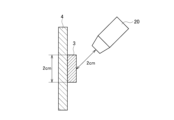
- FIG. 3 is a schematic diagram showing an example of the relationship between a reduction electrode and a blower shown in FIG. 2
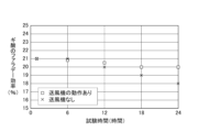
- FIG. 10 is a diagram showing experimental results of Experiment 1
- FIG. 4 is a schematic diagram showing another example of the relationship example shown in FIG. 3
- FIG. 4 is a schematic diagram showing another example of the relationship example shown in FIG. 3
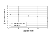
- FIG. 10 is a diagram showing experimental results of Experiment 2
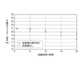
- FIG. 10 is a diagram showing experimental results of Experiment 3;
- the carbon dioxide reducer 100 produces both gaseous and liquid reduction products through redox reactions.
- the gas containing carbon dioxide may be supplied from the supply port 8 and the air may be supplied from the supply port 9, for example.
- the gas supplied from the supply port 9 may be nitrogen, argon, helium, or the like.
- the substrate 1 does not have to be a substrate using a material such as sapphire that transmits light.
- the substrate 1 may be made of, for example, a glass epoxy resin or the like that does not transmit light.
- the light 13 is sunlight, for example. Note that the light 13 may not be sunlight. For example, it may be a xenon lamp, a simulated solar light source, a halogen lamp, a mercury lamp, or a combination of these light sources.
- the reduction electrode 3 is connected to the electrolyte membrane 4 .
- the reduction electrode 3 has a plate-like shape, and FIG. 1 shows an example in which one surface of the reduction electrode 3 is in contact with the surface (YZ surface) of the electrolyte membrane 4 on the outside (the reduction portion 7 side).
- the reduction electrode 3 is electrically connected to the oxidation electrode 2 via a lead wire whose reference numeral is omitted.
- the reduction electrode 3 for example, copper, platinum, gold, silver, indium, palladium, gallium, nickel, tin, cadmium, or any porous material of their alloys can be used.
- the reduction electrode 3 is composed of compounds such as silver oxide, copper oxide, copper (II) oxide, nickel oxide, indium oxide, tin oxide, tungsten oxide, tungsten (VI) oxide, and copper oxide, or metal ions and anionic ligands. It may be a porous metal complex having ligands. Note that the reduction electrode 3 may be arranged so as to form a plane in the X direction, like the electrolyte membrane 4 described later.
- the surface of the reduction electrode 3 is covered with carbon dioxide supplied from the supply ports 8 and 9. As a result, an oxidation-reduction reaction occurs on the surface of the reduction electrode 3 to produce reduction products such as hydrogen, carbon monoxide, methane, and other gases, and liquid reduction products, such as formic acid, methanol, and ethanol.
- Reduction products such as hydrogen, carbon monoxide, and methane have smaller molecular weights than carbon dioxide and are lighter, and are discharged to the outside from the gas recovery port 11 provided at the top of the reduction unit 7 .
- the liquid reduction product is discharged to the outside from a liquid recovery port 12 provided in the upper portion of the reducing section 7 . Even without the gas recovery port 11 and the liquid recovery port 12, the carbon dioxide reduction reaction is not affected. Therefore, the gas recovery port 11 and the liquid recovery port 12 are not essential components in this embodiment.
- the blower 10 may always generate an airflow, or may generate it intermittently.
- the gas supplied from the supply port 9 may also be intermittently supplied according to the operation of the blower 10 . That is, the blower 10 may be operated intermittently. Power consumption can be reduced more than when the blower 10 is operated all the time.
- the carbon dioxide reduction apparatus 100 includes the oxidation electrode 2 that receives the light 13 from the outside, the oxidation tank 6 that holds the electrolytic solution 5 in which the oxidation electrode 2 is immersed, and the oxidation An electrolyte membrane 4 constituting a part of one surface of the tank 6 excluding the surface on which the light 13 is incident, a reduction electrode 3 connected to the electrolyte membrane 4, and a gas containing carbon dioxide is supplied from the outside on which the reduction electrode 3 is arranged.
- a reducing section 7 for supplying air, and a blower 10 for generating an air flow toward the reducing electrode 3 inside the reducing section 7 are provided. Accordingly, it is possible to provide a carbon dioxide reduction apparatus capable of improving the decrease in the reaction efficiency of the reduction reaction.
- FIG. 2 is a schematic diagram showing a modification of the carbon dioxide reduction device 100. As shown in FIG. The modification shown in FIG. 2 differs from the carbon dioxide reduction device 100 (FIG. 1) in that it includes an air blower 20 .
- the blower 20 is a mass flow controller provided at the tip inside the supply port 9 to which pressurized carbon dioxide is supplied.
- a mass flow controller measures the mass flow rate of a fluid to control the flow rate, and is sometimes referred to as a variable flow rate device.
- the reduction product (liquid) on the surface can be eliminated. Therefore, it is possible to improve the decrease in the reaction efficiency of the reduction reaction.
- the gas to be injected does not have to be carbon dioxide. Gases such as air, nitrogen, argon, and helium may be used.
- the oxidation electrode 2 is formed by epitaxially growing a thin film of GaN, which is an n-type semiconductor, and AlGaN in this order on a substrate (sapphire substrate) 1, vacuum-depositing Ni thereon, and performing a heat treatment to form a thin NiO co-catalyst film. Configured. The oxidation electrode 2 was immersed in the electrolytic solution 5 .
- a 1.0 mol/L sodium hydroxide aqueous solution was used as the electrolyte solution 5.
- Nafion (registered trademark) was used for the electrolyte membrane 4.
- the air blower 20 used was manufactured by Koflock (MODEL EX-250S SERIES).
- the air blower 20 was connected to the carbon dioxide cylinder through the supply port 9 , and arranged so that the carbon dioxide was injected perpendicularly to the surface of the reduction electrode 3 .
- the flow rate of carbon dioxide was set at, for example, 5 ml/min and the pressure at 0.5 MPa.
- the gas and liquid generated in the oxidation tank 6 and the reduction section 7 were sampled and analyzed using a gas chromatograph, a liquid chromatograph, and a gas chromatograph mass spectrometer.
- the Faraday efficiency of the carbon dioxide reduction reaction was calculated from the experimental results under the above experimental conditions.
- the Faradaic efficiency of carbon dioxide indicates the ratio of the number of electrons used in the carbon dioxide reduction reaction to the number of electrons transferred between the oxidation electrode 2 and the reduction electrode 3 by light irradiation or voltage application.
- the number of electrons when the reduction product is liquid can be calculated by the following formula.
- C is the concentration of the reduction reaction product (mol/L)
- Vl is the volume of the liquid sample (L)
- Z is the number of electrons required for the reduction reaction
- F is the Faraday constant (C/mol).
- the blower 20 was arranged so that the jet of carbon dioxide from the blower 20 hits the reduction electrode 3 perpendicularly. As shown in FIG. 3, the distance between the tip of the blower 20 and the reduction electrode 3 was set to 2 cm.
- the supply pressure of carbon dioxide was set to 1.0 MPa, and carbon dioxide was injected for 5 seconds at a cycle of 1 minute. This injection of carbon dioxide can remove the liquid (droplets) generated on the surface of the reduction electrode 3 by the reduction reaction.
- FIG. 4 shows the experimental results of Experiment 1.
- the horizontal axis of FIG. 4 is test time (reduction time), and the vertical axis is Faraday efficiency (%) of formic acid.
- ⁇ is a plot with the blower 20 operating, and ⁇ is a plot without the blower 20 of the comparative example.
- the Faraday efficiency which was approximately 21% after 6 hours of testing, decreases to approximately 18% after 24 hours of testing without the blower 20 .
- the Faraday efficiency for a test time of 24 hours is about 20%, and it can be seen that the decrease in Faraday efficiency can be improved (-3% ⁇ -1%).
- the blower 20 When the reduction electrode 3 is arranged upright in the Z direction, it is preferable to arrange the blower 20 above the upper end of the reduction electrode 3 as shown in FIGS.
- the liquid (reduction product) generated on the surface of the reduction electrode 3 descends downward due to gravity. Therefore, by injecting carbon dioxide from above, it is possible to promote movement of the liquid and prevent redeposition of the liquid to the surface of the reduction electrode 3 .
- a propeller fan (LittleFAN40U manufactured by Timely) was used as the blower 10 .
- the propeller fan was rotated at 5000 rpm. Therefore, the flow of carbon dioxide generated by the blower 10 always hits the surface of the reduction electrode 3 .
- FIG. 7 shows the experimental results of Experiment 2. The relationship between the horizontal axis and the vertical axis in FIG. 7 is the same as in FIG.
- FIG. 8 shows the experimental results of Experiment 3.
- the relationship between the horizontal axis and the vertical axis in FIG. 8 is the same as in FIGS.
- the present invention is not limited to the above embodiments, and can be modified within the scope of the gist.
- the light 13 is generated by a xenon lamp in the embodiment, sunlight may be used.
- the electrolyte membrane 4 and the reduction electrode 3 may be configured integrally.
- the electrolyte membrane 4 and the reduction electrode 3 may be replaced with a gas diffusion electrode (GDE (registered trademark)) composed of a porous member and a catalyst. The number of parts can be reduced.
- GDE gas diffusion electrode
- the electrolyte membrane 4 and the reduction electrode 3 may be integrated by press-fitting the electrolyte membrane 4 into the copper of the porous body.
- blowers 10 and 20 have been described with an example in which they are arranged in front of the supply port 9 , but the blowers 10 and 20 may be arranged in front of the supply port 8 .
- the present invention can be widely used in fields related to carbon dioxide recycling.
- Substrate 2 Oxidation electrode 3: Reduction electrode 4: Electrolyte membrane 5: Electrolyte 6: Oxidation tank 7: Reduction part 8, 9: Supply ports 10, 20: Blower 11: Gas recovery port 12: Liquid recovery port 13: light
Landscapes
- Chemical & Material Sciences (AREA)
- Organic Chemistry (AREA)
- Engineering & Computer Science (AREA)
- Chemical Kinetics & Catalysis (AREA)
- Electrochemistry (AREA)
- Materials Engineering (AREA)
- Metallurgy (AREA)
- Inorganic Chemistry (AREA)
- Electrolytic Production Of Non-Metals, Compounds, Apparatuses Therefor (AREA)
- Physical Or Chemical Processes And Apparatus (AREA)
Priority Applications (3)
| Application Number | Priority Date | Filing Date | Title |
|---|---|---|---|
| US18/698,460 US20240328003A1 (en) | 2021-11-04 | 2021-11-04 | Carbon Dioxide Reduction Device |
| PCT/JP2021/040551 WO2023079612A1 (ja) | 2021-11-04 | 2021-11-04 | 二酸化炭素還元装置 |
| JP2023557880A JP7783507B2 (ja) | 2021-11-04 | 2021-11-04 | 二酸化炭素還元装置 |
Applications Claiming Priority (1)
| Application Number | Priority Date | Filing Date | Title |
|---|---|---|---|
| PCT/JP2021/040551 WO2023079612A1 (ja) | 2021-11-04 | 2021-11-04 | 二酸化炭素還元装置 |
Publications (2)
| Publication Number | Publication Date |
|---|---|
| WO2023079612A1 true WO2023079612A1 (ja) | 2023-05-11 |
| WO2023079612A9 WO2023079612A9 (ja) | 2024-06-06 |
Family
ID=86240770
Family Applications (1)
| Application Number | Title | Priority Date | Filing Date |
|---|---|---|---|
| PCT/JP2021/040551 Ceased WO2023079612A1 (ja) | 2021-11-04 | 2021-11-04 | 二酸化炭素還元装置 |
Country Status (3)
| Country | Link |
|---|---|
| US (1) | US20240328003A1 (https=) |
| JP (1) | JP7783507B2 (https=) |
| WO (1) | WO2023079612A1 (https=) |
Citations (5)
| Publication number | Priority date | Publication date | Assignee | Title |
|---|---|---|---|---|
| JP2006225218A (ja) * | 2005-02-21 | 2006-08-31 | Teijin Pharma Ltd | 電気化学的酸素発生素子 |
| WO2012128148A1 (ja) * | 2011-03-18 | 2012-09-27 | 国立大学法人長岡技術科学大学 | 二酸化炭素の還元固定化システム、二酸化炭素の還元固定化方法、及び有用炭素資源の製造方法 |
| JP2020023726A (ja) * | 2018-08-06 | 2020-02-13 | 富士通株式会社 | 二酸化炭素還元用電極、及び二酸化炭素還元装置 |
| WO2020121556A1 (ja) * | 2018-12-10 | 2020-06-18 | 日本電信電話株式会社 | 二酸化炭素の気相還元装置及び二酸化炭素の気相還元方法 |
| JP2021059760A (ja) * | 2019-10-08 | 2021-04-15 | 株式会社豊田中央研究所 | Co2還元反応装置 |
Family Cites Families (1)
| Publication number | Priority date | Publication date | Assignee | Title |
|---|---|---|---|---|
| KR101738590B1 (ko) * | 2015-07-14 | 2017-06-09 | 한국에너지기술연구원 | 이산화탄소를 전기환원시켜 이산화탄소의 환원 생성물을 제조하는 방법 및 장치 |
-
2021
- 2021-11-04 JP JP2023557880A patent/JP7783507B2/ja active Active
- 2021-11-04 WO PCT/JP2021/040551 patent/WO2023079612A1/ja not_active Ceased
- 2021-11-04 US US18/698,460 patent/US20240328003A1/en active Pending
Patent Citations (5)
| Publication number | Priority date | Publication date | Assignee | Title |
|---|---|---|---|---|
| JP2006225218A (ja) * | 2005-02-21 | 2006-08-31 | Teijin Pharma Ltd | 電気化学的酸素発生素子 |
| WO2012128148A1 (ja) * | 2011-03-18 | 2012-09-27 | 国立大学法人長岡技術科学大学 | 二酸化炭素の還元固定化システム、二酸化炭素の還元固定化方法、及び有用炭素資源の製造方法 |
| JP2020023726A (ja) * | 2018-08-06 | 2020-02-13 | 富士通株式会社 | 二酸化炭素還元用電極、及び二酸化炭素還元装置 |
| WO2020121556A1 (ja) * | 2018-12-10 | 2020-06-18 | 日本電信電話株式会社 | 二酸化炭素の気相還元装置及び二酸化炭素の気相還元方法 |
| JP2021059760A (ja) * | 2019-10-08 | 2021-04-15 | 株式会社豊田中央研究所 | Co2還元反応装置 |
Also Published As
| Publication number | Publication date |
|---|---|
| JPWO2023079612A1 (https=) | 2023-05-11 |
| JP7783507B2 (ja) | 2025-12-10 |
| WO2023079612A9 (ja) | 2024-06-06 |
| US20240328003A1 (en) | 2024-10-03 |
Similar Documents
| Publication | Publication Date | Title |
|---|---|---|
| Wang et al. | Efficient solar-driven electrocatalytic CO2 reduction in a redox-medium-assisted system | |
| Pawar et al. | General review on the components and parameters of photoelectrochemical system for CO2 reduction with in situ analysis | |
| CN112593251B (zh) | 电化学反应装置 | |
| DiMeglio et al. | Selective conversion of CO2 to CO with high efficiency using an inexpensive bismuth-based electrocatalyst | |
| Jeon et al. | A monolithic and standalone solar-fuel device having comparable efficiency to photosynthesis in nature | |
| CN102284293B (zh) | 用于催化还原CO2为有机燃料的Cu/Cu2O薄膜材料 | |
| JP5753641B2 (ja) | 二酸化炭素還元装置および二酸化炭素を還元する方法 | |
| CN113502488A (zh) | 二氧化碳反应装置 | |
| EP2694702A1 (en) | Proton exchange membrane electrolysis using water vapor as a feedstock | |
| JPWO2012137240A1 (ja) | 半導体素子 | |
| Genovese et al. | A gas-phase electrochemical reactor for carbon dioxide reduction back to liquid fuels | |
| JP7747990B2 (ja) | 多孔質電極支持型電解質膜および多孔質電極支持型電解質膜の製造方法 | |
| JP2018090838A (ja) | 二酸化炭素還元装置 | |
| JP6997376B2 (ja) | 二酸化炭素還元装置 | |
| JP2015004112A (ja) | 電解合成装置 | |
| JP7783507B2 (ja) | 二酸化炭素還元装置 | |
| JP7356067B2 (ja) | 二酸化炭素の気相還元装置、および、二酸化炭素の気相還元方法 | |
| WO2024116355A1 (ja) | 二酸化炭素還元装置 | |
| JP2019203163A (ja) | 電解還元装置及び電解還元方法 | |
| Antoniadou et al. | Solar energy conversion using photo-fuel-cells | |
| JP7598059B2 (ja) | 二酸化炭素還元装置 | |
| Varghese et al. | Conversion of Water and CO2 to Fuels Using Solar Energy: Science, Technology and Materials | |
| US20250333861A1 (en) | Reduction Electrode and Manufacturing Method of Reduction Electrode | |
| Kwon et al. | Electronic Switching between Hot Electrons and Hot Holes via Schottky Junctions during Chemical Reactions | |
| WO2026004053A1 (ja) | 二酸化炭素の気相還元装置 |
Legal Events
| Date | Code | Title | Description |
|---|---|---|---|
| 121 | Ep: the epo has been informed by wipo that ep was designated in this application |
Ref document number: 21963209 Country of ref document: EP Kind code of ref document: A1 |
|
| WWE | Wipo information: entry into national phase |
Ref document number: 18698460 Country of ref document: US |
|
| ENP | Entry into the national phase |
Ref document number: 2023557880 Country of ref document: JP Kind code of ref document: A |
|
| NENP | Non-entry into the national phase |
Ref country code: DE |
|
| 122 | Ep: pct application non-entry in european phase |
Ref document number: 21963209 Country of ref document: EP Kind code of ref document: A1 |