WO2023079612A1 - 二酸化炭素還元装置 - Google Patents
二酸化炭素還元装置 Download PDFInfo
- Publication number
- WO2023079612A1 WO2023079612A1 PCT/JP2021/040551 JP2021040551W WO2023079612A1 WO 2023079612 A1 WO2023079612 A1 WO 2023079612A1 JP 2021040551 W JP2021040551 W JP 2021040551W WO 2023079612 A1 WO2023079612 A1 WO 2023079612A1
- Authority
- WO
- WIPO (PCT)
- Prior art keywords
- reduction
- carbon dioxide
- electrode
- blower
- reduction electrode
- Prior art date
Links
- CURLTUGMZLYLDI-UHFFFAOYSA-N Carbon dioxide Chemical compound O=C=O CURLTUGMZLYLDI-UHFFFAOYSA-N 0.000 title claims abstract description 154
- 239000001569 carbon dioxide Substances 0.000 title claims abstract description 77
- 229910002092 carbon dioxide Inorganic materials 0.000 title claims abstract description 77
- 238000007254 oxidation reaction Methods 0.000 claims abstract description 38
- 230000003647 oxidation Effects 0.000 claims abstract description 37
- 239000003792 electrolyte Substances 0.000 claims abstract description 32
- 239000012528 membrane Substances 0.000 claims description 26
- 239000008151 electrolyte solution Substances 0.000 claims description 7
- 238000006722 reduction reaction Methods 0.000 description 125
- 239000007789 gas Substances 0.000 description 22
- 239000007788 liquid Substances 0.000 description 22
- 238000002474 experimental method Methods 0.000 description 15
- 239000000047 product Substances 0.000 description 15
- 238000006243 chemical reaction Methods 0.000 description 12
- 239000000243 solution Substances 0.000 description 12
- 238000010586 diagram Methods 0.000 description 11
- VNWKTOKETHGBQD-UHFFFAOYSA-N methane Chemical compound C VNWKTOKETHGBQD-UHFFFAOYSA-N 0.000 description 10
- 238000011084 recovery Methods 0.000 description 10
- 239000000758 substrate Substances 0.000 description 9
- 230000007423 decrease Effects 0.000 description 8
- BDAGIHXWWSANSR-UHFFFAOYSA-N methanoic acid Natural products OC=O BDAGIHXWWSANSR-UHFFFAOYSA-N 0.000 description 8
- IJGRMHOSHXDMSA-UHFFFAOYSA-N Atomic nitrogen Chemical compound N#N IJGRMHOSHXDMSA-UHFFFAOYSA-N 0.000 description 6
- LFQSCWFLJHTTHZ-UHFFFAOYSA-N Ethanol Chemical compound CCO LFQSCWFLJHTTHZ-UHFFFAOYSA-N 0.000 description 6
- OKKJLVBELUTLKV-UHFFFAOYSA-N Methanol Chemical compound OC OKKJLVBELUTLKV-UHFFFAOYSA-N 0.000 description 6
- QPLDLSVMHZLSFG-UHFFFAOYSA-N Copper oxide Chemical compound [Cu]=O QPLDLSVMHZLSFG-UHFFFAOYSA-N 0.000 description 5
- OSWFIVFLDKOXQC-UHFFFAOYSA-N 4-(3-methoxyphenyl)aniline Chemical compound COC1=CC=CC(C=2C=CC(N)=CC=2)=C1 OSWFIVFLDKOXQC-UHFFFAOYSA-N 0.000 description 4
- XKRFYHLGVUSROY-UHFFFAOYSA-N Argon Chemical compound [Ar] XKRFYHLGVUSROY-UHFFFAOYSA-N 0.000 description 4
- UGFAIRIUMAVXCW-UHFFFAOYSA-N Carbon monoxide Chemical compound [O+]#[C-] UGFAIRIUMAVXCW-UHFFFAOYSA-N 0.000 description 4
- 229910002091 carbon monoxide Inorganic materials 0.000 description 4
- 235000019253 formic acid Nutrition 0.000 description 4
- 239000001257 hydrogen Substances 0.000 description 4
- 229910052739 hydrogen Inorganic materials 0.000 description 4
- 238000012986 modification Methods 0.000 description 4
- 230000004048 modification Effects 0.000 description 4
- 238000012360 testing method Methods 0.000 description 4
- RYGMFSIKBFXOCR-UHFFFAOYSA-N Copper Chemical compound [Cu] RYGMFSIKBFXOCR-UHFFFAOYSA-N 0.000 description 3
- PXHVJJICTQNCMI-UHFFFAOYSA-N Nickel Chemical compound [Ni] PXHVJJICTQNCMI-UHFFFAOYSA-N 0.000 description 3
- HEMHJVSKTPXQMS-UHFFFAOYSA-M Sodium hydroxide Chemical compound [OH-].[Na+] HEMHJVSKTPXQMS-UHFFFAOYSA-M 0.000 description 3
- 239000007795 chemical reaction product Substances 0.000 description 3
- 150000001875 compounds Chemical class 0.000 description 3
- 229910052802 copper Inorganic materials 0.000 description 3
- 239000010949 copper Substances 0.000 description 3
- 238000009792 diffusion process Methods 0.000 description 3
- 238000005516 engineering process Methods 0.000 description 3
- 150000002431 hydrogen Chemical class 0.000 description 3
- 229910052757 nitrogen Inorganic materials 0.000 description 3
- 239000012071 phase Substances 0.000 description 3
- 229910052594 sapphire Inorganic materials 0.000 description 3
- 239000010980 sapphire Substances 0.000 description 3
- 229910052724 xenon Inorganic materials 0.000 description 3
- FHNFHKCVQCLJFQ-UHFFFAOYSA-N xenon atom Chemical compound [Xe] FHNFHKCVQCLJFQ-UHFFFAOYSA-N 0.000 description 3
- 239000005751 Copper oxide Substances 0.000 description 2
- 229920000557 Nafion® Polymers 0.000 description 2
- KDLHZDBZIXYQEI-UHFFFAOYSA-N Palladium Chemical compound [Pd] KDLHZDBZIXYQEI-UHFFFAOYSA-N 0.000 description 2
- WCUXLLCKKVVCTQ-UHFFFAOYSA-M Potassium chloride Chemical compound [Cl-].[K+] WCUXLLCKKVVCTQ-UHFFFAOYSA-M 0.000 description 2
- UIIMBOGNXHQVGW-UHFFFAOYSA-M Sodium bicarbonate Chemical compound [Na+].OC([O-])=O UIIMBOGNXHQVGW-UHFFFAOYSA-M 0.000 description 2
- FAPWRFPIFSIZLT-UHFFFAOYSA-M Sodium chloride Chemical compound [Na+].[Cl-] FAPWRFPIFSIZLT-UHFFFAOYSA-M 0.000 description 2
- 229910052786 argon Inorganic materials 0.000 description 2
- 229910000431 copper oxide Inorganic materials 0.000 description 2
- 239000002803 fossil fuel Substances 0.000 description 2
- 230000005484 gravity Effects 0.000 description 2
- 239000001307 helium Substances 0.000 description 2
- 229910052734 helium Inorganic materials 0.000 description 2
- SWQJXJOGLNCZEY-UHFFFAOYSA-N helium atom Chemical compound [He] SWQJXJOGLNCZEY-UHFFFAOYSA-N 0.000 description 2
- 239000003446 ligand Substances 0.000 description 2
- 230000007774 longterm Effects 0.000 description 2
- 238000004519 manufacturing process Methods 0.000 description 2
- BASFCYQUMIYNBI-UHFFFAOYSA-N platinum Chemical compound [Pt] BASFCYQUMIYNBI-UHFFFAOYSA-N 0.000 description 2
- 238000006479 redox reaction Methods 0.000 description 2
- CPRMKOQKXYSDML-UHFFFAOYSA-M rubidium hydroxide Chemical compound [OH-].[Rb+] CPRMKOQKXYSDML-UHFFFAOYSA-M 0.000 description 2
- 239000004065 semiconductor Substances 0.000 description 2
- NDVLTYZPCACLMA-UHFFFAOYSA-N silver oxide Chemical compound [O-2].[Ag+].[Ag+] NDVLTYZPCACLMA-UHFFFAOYSA-N 0.000 description 2
- XLYOFNOQVPJJNP-UHFFFAOYSA-N water Substances O XLYOFNOQVPJJNP-UHFFFAOYSA-N 0.000 description 2
- MFGOFGRYDNHJTA-UHFFFAOYSA-N 2-amino-1-(2-fluorophenyl)ethanol Chemical compound NCC(O)C1=CC=CC=C1F MFGOFGRYDNHJTA-UHFFFAOYSA-N 0.000 description 1
- 229910002704 AlGaN Inorganic materials 0.000 description 1
- 229910002915 BiVO4 Inorganic materials 0.000 description 1
- 239000004215 Carbon black (E152) Substances 0.000 description 1
- GYHNNYVSQQEPJS-UHFFFAOYSA-N Gallium Chemical compound [Ga] GYHNNYVSQQEPJS-UHFFFAOYSA-N 0.000 description 1
- UFHFLCQGNIYNRP-UHFFFAOYSA-N Hydrogen Chemical compound [H][H] UFHFLCQGNIYNRP-UHFFFAOYSA-N 0.000 description 1
- KWYUFKZDYYNOTN-UHFFFAOYSA-M Potassium hydroxide Chemical compound [OH-].[K+] KWYUFKZDYYNOTN-UHFFFAOYSA-M 0.000 description 1
- 239000012327 Ruthenium complex Substances 0.000 description 1
- BQCADISMDOOEFD-UHFFFAOYSA-N Silver Chemical compound [Ag] BQCADISMDOOEFD-UHFFFAOYSA-N 0.000 description 1
- ATJFFYVFTNAWJD-UHFFFAOYSA-N Tin Chemical compound [Sn] ATJFFYVFTNAWJD-UHFFFAOYSA-N 0.000 description 1
- GWEVSGVZZGPLCZ-UHFFFAOYSA-N Titan oxide Chemical compound O=[Ti]=O GWEVSGVZZGPLCZ-UHFFFAOYSA-N 0.000 description 1
- PRPAGESBURMWTI-UHFFFAOYSA-N [C].[F] Chemical group [C].[F] PRPAGESBURMWTI-UHFFFAOYSA-N 0.000 description 1
- 239000003570 air Substances 0.000 description 1
- 229910045601 alloy Inorganic materials 0.000 description 1
- 239000000956 alloy Substances 0.000 description 1
- 229910021417 amorphous silicon Inorganic materials 0.000 description 1
- 125000000129 anionic group Chemical group 0.000 description 1
- 239000007864 aqueous solution Substances 0.000 description 1
- QVGXLLKOCUKJST-UHFFFAOYSA-N atomic oxygen Chemical compound [O] QVGXLLKOCUKJST-UHFFFAOYSA-N 0.000 description 1
- OVHDZBAFUMEXCX-UHFFFAOYSA-N benzyl 4-methylbenzenesulfonate Chemical compound C1=CC(C)=CC=C1S(=O)(=O)OCC1=CC=CC=C1 OVHDZBAFUMEXCX-UHFFFAOYSA-N 0.000 description 1
- 229910052793 cadmium Inorganic materials 0.000 description 1
- BDOSMKKIYDKNTQ-UHFFFAOYSA-N cadmium atom Chemical compound [Cd] BDOSMKKIYDKNTQ-UHFFFAOYSA-N 0.000 description 1
- HUCVOHYBFXVBRW-UHFFFAOYSA-M caesium hydroxide Inorganic materials [OH-].[Cs+] HUCVOHYBFXVBRW-UHFFFAOYSA-M 0.000 description 1
- 239000012159 carrier gas Substances 0.000 description 1
- 239000003054 catalyst Substances 0.000 description 1
- 239000003638 chemical reducing agent Substances 0.000 description 1
- 239000003426 co-catalyst Substances 0.000 description 1
- 230000000052 comparative effect Effects 0.000 description 1
- 150000004696 coordination complex Chemical class 0.000 description 1
- 238000000151 deposition Methods 0.000 description 1
- 238000011161 development Methods 0.000 description 1
- 230000000694 effects Effects 0.000 description 1
- 238000002848 electrochemical method Methods 0.000 description 1
- 239000003822 epoxy resin Substances 0.000 description 1
- 239000010408 film Substances 0.000 description 1
- 239000012530 fluid Substances 0.000 description 1
- 229910052733 gallium Inorganic materials 0.000 description 1
- 239000011521 glass Substances 0.000 description 1
- PCHJSUWPFVWCPO-UHFFFAOYSA-N gold Chemical compound [Au] PCHJSUWPFVWCPO-UHFFFAOYSA-N 0.000 description 1
- 229910052737 gold Inorganic materials 0.000 description 1
- 239000010931 gold Substances 0.000 description 1
- 229910052736 halogen Inorganic materials 0.000 description 1
- 150000002367 halogens Chemical class 0.000 description 1
- 238000010438 heat treatment Methods 0.000 description 1
- 229930195733 hydrocarbon Natural products 0.000 description 1
- 150000002430 hydrocarbons Chemical class 0.000 description 1
- 229910052738 indium Inorganic materials 0.000 description 1
- APFVFJFRJDLVQX-UHFFFAOYSA-N indium atom Chemical compound [In] APFVFJFRJDLVQX-UHFFFAOYSA-N 0.000 description 1
- 229910003437 indium oxide Inorganic materials 0.000 description 1
- PJXISJQVUVHSOJ-UHFFFAOYSA-N indium(iii) oxide Chemical compound [O-2].[O-2].[O-2].[In+3].[In+3] PJXISJQVUVHSOJ-UHFFFAOYSA-N 0.000 description 1
- 238000002347 injection Methods 0.000 description 1
- 239000007924 injection Substances 0.000 description 1
- WABPQHHGFIMREM-UHFFFAOYSA-N lead(0) Chemical compound [Pb] WABPQHHGFIMREM-UHFFFAOYSA-N 0.000 description 1
- 239000007791 liquid phase Substances 0.000 description 1
- 239000000463 material Substances 0.000 description 1
- QSHDDOUJBYECFT-UHFFFAOYSA-N mercury Chemical compound [Hg] QSHDDOUJBYECFT-UHFFFAOYSA-N 0.000 description 1
- 229910052753 mercury Inorganic materials 0.000 description 1
- 229910021645 metal ion Inorganic materials 0.000 description 1
- 229910052759 nickel Inorganic materials 0.000 description 1
- 229910000480 nickel oxide Inorganic materials 0.000 description 1
- 150000004767 nitrides Chemical class 0.000 description 1
- QGLKJKCYBOYXKC-UHFFFAOYSA-N nonaoxidotritungsten Chemical compound O=[W]1(=O)O[W](=O)(=O)O[W](=O)(=O)O1 QGLKJKCYBOYXKC-UHFFFAOYSA-N 0.000 description 1
- GNRSAWUEBMWBQH-UHFFFAOYSA-N oxonickel Chemical compound [Ni]=O GNRSAWUEBMWBQH-UHFFFAOYSA-N 0.000 description 1
- 239000001301 oxygen Substances 0.000 description 1
- 229910052760 oxygen Inorganic materials 0.000 description 1
- 229910052763 palladium Inorganic materials 0.000 description 1
- 229910052697 platinum Inorganic materials 0.000 description 1
- 229920000647 polyepoxide Polymers 0.000 description 1
- 239000011148 porous material Substances 0.000 description 1
- 235000015497 potassium bicarbonate Nutrition 0.000 description 1
- 229910000028 potassium bicarbonate Inorganic materials 0.000 description 1
- 239000011736 potassium bicarbonate Substances 0.000 description 1
- 239000001103 potassium chloride Substances 0.000 description 1
- 235000011164 potassium chloride Nutrition 0.000 description 1
- TYJJADVDDVDEDZ-UHFFFAOYSA-M potassium hydrogencarbonate Chemical compound [K+].OC([O-])=O TYJJADVDDVDEDZ-UHFFFAOYSA-M 0.000 description 1
- 229940086066 potassium hydrogencarbonate Drugs 0.000 description 1
- 238000010248 power generation Methods 0.000 description 1
- 239000002994 raw material Substances 0.000 description 1
- 238000004064 recycling Methods 0.000 description 1
- 238000011160 research Methods 0.000 description 1
- 238000012552 review Methods 0.000 description 1
- 229910052702 rhenium Inorganic materials 0.000 description 1
- WUAPFZMCVAUBPE-UHFFFAOYSA-N rhenium atom Chemical compound [Re] WUAPFZMCVAUBPE-UHFFFAOYSA-N 0.000 description 1
- 229910052709 silver Inorganic materials 0.000 description 1
- 239000004332 silver Substances 0.000 description 1
- 229910001923 silver oxide Inorganic materials 0.000 description 1
- 235000017557 sodium bicarbonate Nutrition 0.000 description 1
- 229910000030 sodium bicarbonate Inorganic materials 0.000 description 1
- 239000011780 sodium chloride Substances 0.000 description 1
- 239000000126 substance Substances 0.000 description 1
- 239000010409 thin film Substances 0.000 description 1
- 229910052718 tin Inorganic materials 0.000 description 1
- XOLBLPGZBRYERU-UHFFFAOYSA-N tin dioxide Chemical compound O=[Sn]=O XOLBLPGZBRYERU-UHFFFAOYSA-N 0.000 description 1
- 229910001887 tin oxide Inorganic materials 0.000 description 1
- OGIDPMRJRNCKJF-UHFFFAOYSA-N titanium oxide Inorganic materials [Ti]=O OGIDPMRJRNCKJF-UHFFFAOYSA-N 0.000 description 1
- 229910001930 tungsten oxide Inorganic materials 0.000 description 1
- ZNOKGRXACCSDPY-UHFFFAOYSA-N tungsten(VI) oxide Inorganic materials O=[W](=O)=O ZNOKGRXACCSDPY-UHFFFAOYSA-N 0.000 description 1
- 238000010792 warming Methods 0.000 description 1
Images


Classifications
-
- C—CHEMISTRY; METALLURGY
- C25—ELECTROLYTIC OR ELECTROPHORETIC PROCESSES; APPARATUS THEREFOR
- C25B—ELECTROLYTIC OR ELECTROPHORETIC PROCESSES FOR THE PRODUCTION OF COMPOUNDS OR NON-METALS; APPARATUS THEREFOR
- C25B1/00—Electrolytic production of inorganic compounds or non-metals
- C25B1/01—Products
- C25B1/23—Carbon monoxide or syngas
-
- C—CHEMISTRY; METALLURGY
- C25—ELECTROLYTIC OR ELECTROPHORETIC PROCESSES; APPARATUS THEREFOR
- C25B—ELECTROLYTIC OR ELECTROPHORETIC PROCESSES FOR THE PRODUCTION OF COMPOUNDS OR NON-METALS; APPARATUS THEREFOR
- C25B3/00—Electrolytic production of organic compounds
- C25B3/20—Processes
- C25B3/25—Reduction
- C25B3/26—Reduction of carbon dioxide
-
- C—CHEMISTRY; METALLURGY
- C25—ELECTROLYTIC OR ELECTROPHORETIC PROCESSES; APPARATUS THEREFOR
- C25B—ELECTROLYTIC OR ELECTROPHORETIC PROCESSES FOR THE PRODUCTION OF COMPOUNDS OR NON-METALS; APPARATUS THEREFOR
- C25B9/00—Cells or assemblies of cells; Constructional parts of cells; Assemblies of constructional parts, e.g. electrode-diaphragm assemblies; Process-related cell features
Definitions
- the present invention relates to a carbon dioxide reduction device.
- Non-Patent Document 1 discloses a carbon dioxide reduction device by light irradiation.
- the reduction device when the oxidation electrode is irradiated with light, electron-hole pairs are generated and separated at the oxidation electrode, and oxygen and protons (H+) are generated by the oxidation reaction of water. Hydrogen is generated by the combination of protons and electrons at the reduction electrode, causing a reduction reaction.
- This reduction reaction produces carbon monoxide, formic acid, methane, and the like that can be used as energy resources.
- Non-Patent Document 1 the reduction electrode is immersed in a solution (electrolyte), and by dissolving carbon dioxide in the solution, carbon dioxide is supplied to the reduction electrode and a reduction reaction is performed. I do.
- this carbon dioxide reduction reaction there is a limit to the dissolved concentration of carbon dioxide in the solution and the diffusion coefficient of carbon dioxide in the solution, and the problem is that the amount of carbon dioxide supplied to the reduction electrode is limited. .
- a carbon dioxide reduction apparatus includes an oxidation electrode that receives light from the outside, an oxidation tank that holds an electrolytic solution in which the oxidation electrode is immersed, and a surface of the oxidation tank on which the light is incident. an electrolyte membrane constituting a part of one surface excluding the electrolyte membrane, a reduction electrode connected to the outer surface of the electrolyte membrane, a reduction section in which the reduction electrode is arranged and a gas containing carbon dioxide is supplied from the outside,
- the gist of the present invention is that the reduction unit includes an air blower for generating an air flow toward the reduction electrode.
- FIG. 1 is a schematic diagram showing a configuration example of a carbon dioxide reduction device according to an embodiment of the present invention
- FIG. FIG. 2 is a schematic diagram showing a modification of the carbon dioxide reduction device shown in FIG. 1
- FIG. 3 is a schematic diagram showing an example of the relationship between a reduction electrode and a blower shown in FIG. 2
- FIG. 10 is a diagram showing experimental results of Experiment 1
- FIG. 4 is a schematic diagram showing another example of the relationship example shown in FIG. 3
- FIG. 4 is a schematic diagram showing another example of the relationship example shown in FIG. 3
- FIG. 10 is a diagram showing experimental results of Experiment 2
- FIG. 10 is a diagram showing experimental results of Experiment 3;
- the carbon dioxide reducer 100 produces both gaseous and liquid reduction products through redox reactions.
- the gas containing carbon dioxide may be supplied from the supply port 8 and the air may be supplied from the supply port 9, for example.
- the gas supplied from the supply port 9 may be nitrogen, argon, helium, or the like.
- the substrate 1 does not have to be a substrate using a material such as sapphire that transmits light.
- the substrate 1 may be made of, for example, a glass epoxy resin or the like that does not transmit light.
- the light 13 is sunlight, for example. Note that the light 13 may not be sunlight. For example, it may be a xenon lamp, a simulated solar light source, a halogen lamp, a mercury lamp, or a combination of these light sources.
- the reduction electrode 3 is connected to the electrolyte membrane 4 .
- the reduction electrode 3 has a plate-like shape, and FIG. 1 shows an example in which one surface of the reduction electrode 3 is in contact with the surface (YZ surface) of the electrolyte membrane 4 on the outside (the reduction portion 7 side).
- the reduction electrode 3 is electrically connected to the oxidation electrode 2 via a lead wire whose reference numeral is omitted.
- the reduction electrode 3 for example, copper, platinum, gold, silver, indium, palladium, gallium, nickel, tin, cadmium, or any porous material of their alloys can be used.
- the reduction electrode 3 is composed of compounds such as silver oxide, copper oxide, copper (II) oxide, nickel oxide, indium oxide, tin oxide, tungsten oxide, tungsten (VI) oxide, and copper oxide, or metal ions and anionic ligands. It may be a porous metal complex having ligands. Note that the reduction electrode 3 may be arranged so as to form a plane in the X direction, like the electrolyte membrane 4 described later.
- the surface of the reduction electrode 3 is covered with carbon dioxide supplied from the supply ports 8 and 9. As a result, an oxidation-reduction reaction occurs on the surface of the reduction electrode 3 to produce reduction products such as hydrogen, carbon monoxide, methane, and other gases, and liquid reduction products, such as formic acid, methanol, and ethanol.
- Reduction products such as hydrogen, carbon monoxide, and methane have smaller molecular weights than carbon dioxide and are lighter, and are discharged to the outside from the gas recovery port 11 provided at the top of the reduction unit 7 .
- the liquid reduction product is discharged to the outside from a liquid recovery port 12 provided in the upper portion of the reducing section 7 . Even without the gas recovery port 11 and the liquid recovery port 12, the carbon dioxide reduction reaction is not affected. Therefore, the gas recovery port 11 and the liquid recovery port 12 are not essential components in this embodiment.
- the blower 10 may always generate an airflow, or may generate it intermittently.
- the gas supplied from the supply port 9 may also be intermittently supplied according to the operation of the blower 10 . That is, the blower 10 may be operated intermittently. Power consumption can be reduced more than when the blower 10 is operated all the time.
- the carbon dioxide reduction apparatus 100 includes the oxidation electrode 2 that receives the light 13 from the outside, the oxidation tank 6 that holds the electrolytic solution 5 in which the oxidation electrode 2 is immersed, and the oxidation An electrolyte membrane 4 constituting a part of one surface of the tank 6 excluding the surface on which the light 13 is incident, a reduction electrode 3 connected to the electrolyte membrane 4, and a gas containing carbon dioxide is supplied from the outside on which the reduction electrode 3 is arranged.
- a reducing section 7 for supplying air, and a blower 10 for generating an air flow toward the reducing electrode 3 inside the reducing section 7 are provided. Accordingly, it is possible to provide a carbon dioxide reduction apparatus capable of improving the decrease in the reaction efficiency of the reduction reaction.
- FIG. 2 is a schematic diagram showing a modification of the carbon dioxide reduction device 100. As shown in FIG. The modification shown in FIG. 2 differs from the carbon dioxide reduction device 100 (FIG. 1) in that it includes an air blower 20 .
- the blower 20 is a mass flow controller provided at the tip inside the supply port 9 to which pressurized carbon dioxide is supplied.
- a mass flow controller measures the mass flow rate of a fluid to control the flow rate, and is sometimes referred to as a variable flow rate device.
- the reduction product (liquid) on the surface can be eliminated. Therefore, it is possible to improve the decrease in the reaction efficiency of the reduction reaction.
- the gas to be injected does not have to be carbon dioxide. Gases such as air, nitrogen, argon, and helium may be used.
- the oxidation electrode 2 is formed by epitaxially growing a thin film of GaN, which is an n-type semiconductor, and AlGaN in this order on a substrate (sapphire substrate) 1, vacuum-depositing Ni thereon, and performing a heat treatment to form a thin NiO co-catalyst film. Configured. The oxidation electrode 2 was immersed in the electrolytic solution 5 .
- a 1.0 mol/L sodium hydroxide aqueous solution was used as the electrolyte solution 5.
- Nafion (registered trademark) was used for the electrolyte membrane 4.
- the air blower 20 used was manufactured by Koflock (MODEL EX-250S SERIES).
- the air blower 20 was connected to the carbon dioxide cylinder through the supply port 9 , and arranged so that the carbon dioxide was injected perpendicularly to the surface of the reduction electrode 3 .
- the flow rate of carbon dioxide was set at, for example, 5 ml/min and the pressure at 0.5 MPa.
- the gas and liquid generated in the oxidation tank 6 and the reduction section 7 were sampled and analyzed using a gas chromatograph, a liquid chromatograph, and a gas chromatograph mass spectrometer.
- the Faraday efficiency of the carbon dioxide reduction reaction was calculated from the experimental results under the above experimental conditions.
- the Faradaic efficiency of carbon dioxide indicates the ratio of the number of electrons used in the carbon dioxide reduction reaction to the number of electrons transferred between the oxidation electrode 2 and the reduction electrode 3 by light irradiation or voltage application.
- the number of electrons when the reduction product is liquid can be calculated by the following formula.
- C is the concentration of the reduction reaction product (mol/L)
- Vl is the volume of the liquid sample (L)
- Z is the number of electrons required for the reduction reaction
- F is the Faraday constant (C/mol).
- the blower 20 was arranged so that the jet of carbon dioxide from the blower 20 hits the reduction electrode 3 perpendicularly. As shown in FIG. 3, the distance between the tip of the blower 20 and the reduction electrode 3 was set to 2 cm.
- the supply pressure of carbon dioxide was set to 1.0 MPa, and carbon dioxide was injected for 5 seconds at a cycle of 1 minute. This injection of carbon dioxide can remove the liquid (droplets) generated on the surface of the reduction electrode 3 by the reduction reaction.
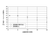
- FIG. 4 shows the experimental results of Experiment 1.
- the horizontal axis of FIG. 4 is test time (reduction time), and the vertical axis is Faraday efficiency (%) of formic acid.
- ⁇ is a plot with the blower 20 operating, and ⁇ is a plot without the blower 20 of the comparative example.
- the Faraday efficiency which was approximately 21% after 6 hours of testing, decreases to approximately 18% after 24 hours of testing without the blower 20 .
- the Faraday efficiency for a test time of 24 hours is about 20%, and it can be seen that the decrease in Faraday efficiency can be improved (-3% ⁇ -1%).
- the blower 20 When the reduction electrode 3 is arranged upright in the Z direction, it is preferable to arrange the blower 20 above the upper end of the reduction electrode 3 as shown in FIGS.
- the liquid (reduction product) generated on the surface of the reduction electrode 3 descends downward due to gravity. Therefore, by injecting carbon dioxide from above, it is possible to promote movement of the liquid and prevent redeposition of the liquid to the surface of the reduction electrode 3 .
- a propeller fan (LittleFAN40U manufactured by Timely) was used as the blower 10 .
- the propeller fan was rotated at 5000 rpm. Therefore, the flow of carbon dioxide generated by the blower 10 always hits the surface of the reduction electrode 3 .
- FIG. 7 shows the experimental results of Experiment 2. The relationship between the horizontal axis and the vertical axis in FIG. 7 is the same as in FIG.
- FIG. 8 shows the experimental results of Experiment 3.
- the relationship between the horizontal axis and the vertical axis in FIG. 8 is the same as in FIGS.
- the present invention is not limited to the above embodiments, and can be modified within the scope of the gist.
- the light 13 is generated by a xenon lamp in the embodiment, sunlight may be used.
- the electrolyte membrane 4 and the reduction electrode 3 may be configured integrally.
- the electrolyte membrane 4 and the reduction electrode 3 may be replaced with a gas diffusion electrode (GDE (registered trademark)) composed of a porous member and a catalyst. The number of parts can be reduced.
- GDE gas diffusion electrode
- the electrolyte membrane 4 and the reduction electrode 3 may be integrated by press-fitting the electrolyte membrane 4 into the copper of the porous body.
- blowers 10 and 20 have been described with an example in which they are arranged in front of the supply port 9 , but the blowers 10 and 20 may be arranged in front of the supply port 8 .
- the present invention can be widely used in fields related to carbon dioxide recycling.
- Substrate 2 Oxidation electrode 3: Reduction electrode 4: Electrolyte membrane 5: Electrolyte 6: Oxidation tank 7: Reduction part 8, 9: Supply ports 10, 20: Blower 11: Gas recovery port 12: Liquid recovery port 13: light
Landscapes
- Chemical & Material Sciences (AREA)
- Organic Chemistry (AREA)
- Engineering & Computer Science (AREA)
- Chemical Kinetics & Catalysis (AREA)
- Electrochemistry (AREA)
- Materials Engineering (AREA)
- Metallurgy (AREA)
- Inorganic Chemistry (AREA)
- Electrolytic Production Of Non-Metals, Compounds, Apparatuses Therefor (AREA)
Abstract
外部からの光13を受光する酸化電極2と、酸化電極2が浸漬される電解液5を保持する酸化槽6と、酸化槽6の光13が入射する面を除いた一面の一部を構成する電解質膜4と、電解質膜4と接続される還元電極3と、還元電極3が配置され外部から二酸化炭素を含む気体が供給される還元部7と、還元部7の内部に還元電極3に向けた気流を生じさせる送風機10とを備え、還元電極3は、板状であり、該還元電極3の一方の面は電解質膜4に接する。
Description
本発明は、二酸化炭素還元装置に関する。
地球温暖化の主因として大気中の二酸化炭素濃度の増加が挙げられている。二酸化炭素の排出量の削減は、世界的規模で長期的な課題になっている。一方、エネルギー問題として中長期的に、化石燃料に頼ったエネルギー供給の見直しが迫られ、次世代のエネルギー供給源の創出が求められている。
二酸化炭素の排出を抑制してエネルギーを得る手段としては、排熱、雪氷熱、振動、電磁波等の未使用エネルギーや、太陽光等の再生可能エネルギーを活用する技術開発が進められている。これらの発電技術は、電気エネルギーを創出するに止まりエネルギーを貯蓄することができない。また、化石燃料を原料とした化学製品を創ることもできない。
これらの課題を同時に解決する方法として、光エネルギーを用いて二酸化炭素を還元する技術が注目されている。非特許文献1は、光照射による二酸化炭素の還元装置を開示している。その還元装置は、酸化電極に光を照射すると、酸化電極で電子・正孔対の生成及び分離が生じ、水の酸化反応により酸素及びプロトン(H+)が生成される。還元電極でプロトンと電子の結合により水素が生成され、還元反応が引き起こされる。この還元反応により、エネルギー資源として利用できる一酸化炭素、ギ酸、及びメタン等が生成される。
Satoshi Yotsuhashi et al."CO2Conversion with Light and Water by GaN Photo electroade",Japanese Journal of Applied Physics,51,2012,p.02BP07-1-p.02BP07-3
Qingxin Jia et al."Direct Gas-phase CO2reduction for Solar Methane Generation Using a Gas Diffusion Electrode with a BiVO4:Mo and a Cu-In-e Photoanode",Chem .Lett.,47,2018,p.436-p.439
非特許文献1に開示された二酸化炭素還元装置は、還元電極が溶液(電解液)に浸漬しており、二酸化炭素を溶液中に溶解させることで、二酸化炭素を還元電極に供給して還元反応を行う。しかしながら、この二酸化炭素還元反応では、溶液での二酸化炭素の溶解濃度や溶液中での二酸化炭素の拡散係数に限界があり、還元電極への二酸化炭素の供給量が制限されることが課題である。
これに対して、還元電極への二酸化炭素供給量を増加させるため、還元電極側の溶液を排除し、二酸化炭素を還元電極へ直接供給する研究が進められている(非特許文献2)。非特許文献2では、還元電極に対して気相の二酸化炭素を供給できる構造を有する反応装置を用いることで、還元電極への二酸化炭素の供給量が増大し、二酸化炭素の還元反応が促進されることが報告されている。
しかしながら、還元反応が進行すると、還元電極の反応表面において、二酸化炭素の還元生成物が生成し、気体である水素、一酸化炭素、メタンだけでなく、液体であるギ酸、メタノール、エタノール等が生成する。また、液相側の溶液が電解質膜を通して気相側に徐々に滲出する。そのため、気相側の還元電極の反応表面がこれらの液体で被覆されてしまい、反応が進行しないという課題がある。
本発明は、この課題に鑑みてなされたものであり、二酸化炭素還元反応の反応効率の低下を改善できる二酸化炭素還元装置を提供することを目的とする。
本発明の一態様に係る二酸化炭素還元装置は、外部からの光を受光する酸化電極と、前記酸化電極が浸漬される電解液を保持する酸化槽と、前記酸化槽の前記光が入射する面を除いた一面の一部を構成する電解質膜と、前記電解質膜の外側の面に接続される還元電極と、前記還元電極が配置され外部から二酸化炭素を含む気体が供給される還元部と、前記還元部の内部に前記還元電極に向けた気流を生じさせる送風機とを備えることを要旨とする。
本発明によれば、二酸化炭素還元反応の反応効率の低下を改善できる二酸化炭素還元装置を提供することができる。
以下、本発明の実施形態について図面を用いて説明する。複数の図面中同一のものには同じ参照符号を付し、説明は繰り返さない。
図1は、本発明の実施形態に係る二酸化炭素還元装置の構成例を示す模式図である。図1において、左右をX方向、図面の奥をY方向、図面の上をZ方向と定義する。
図1に示す二酸化炭素還元装置100は、酸化電極2、酸化槽6、電解質膜4、還元電極3、還元部7、及び送風機10を備える。二酸化炭素還元装置100は、酸化還元反応により、気体と液体の両方の還元生成物を生成する。
光エネルギーを用いて還元する二酸化炭素は、還元部7の上面に設けられた供給口8と、その側面に設けられた供給口9から、還元部7の内部に供給される。供給口8は、例えば二酸化炭素が充填されたボンベに接続され、所定の圧力に減圧された二酸化炭素を定常的に供給する。供給口9は、供給口8から供給される二酸化炭素と同じものを還元部7の側面から供給する。なお、供給口8,9は、どちらか一方を備えればよい。
また、供給口8,9を備える場合は、供給口8から二酸化炭素を含む気体を供給し、供給口9からは例えば空気を供給してもよい。供給口9から供給する気体は、窒素、アルゴン、ヘリウム等であっても構わない。
送風機10は、供給口9の還元部7の内側の前方に配置される。送風機10は、還元部7の内部に、還元電極3に向けた気流を生じさせる。
還元部7の上面には、気体の還元生成物を回収する気体回収口11が設けられる。また、還元部7の下面には、液体の還元生成物を回収する液体回収口12が設けられる。
酸化電極2は、基板1の上に成膜され外部からの光13を受光する。基板1は、XY方向の平面に所定の面積を持つ例えばサファイアである。その基板1の上に、例えば、窒化物半導体、酸化チタン、アモルファスシリコン、ルテニウム錯体、又はレニウム錯体からなる群より選択される少なくとも一つを含む化合物が平面上に成膜されて酸化電極2が形成される。これらの化合物は、光活性やレドックス活性を示す。
なお、基板1は、光を透過するサファイア等の材料を用いた基板でなくても構わない。基板1は光を通さない例えばガラスエポキシ樹脂等で構成してもよい。
光13は、例えば太陽光である。なお、光13は、太陽光で無くても構わない。例えばキセノンランプ、疑似太陽光源、ハロゲンランプ、水銀ランプ、又はこれらの光源の組合せた光であってもよい。
酸化槽6は、酸化電極2が浸漬される電解液5を保持する。電解液5は、例えば、炭酸水素カリウム水溶液、炭酸水素ナトリウム水溶液、塩化カリウム水溶液、塩化ナトリウム水溶液、水酸化カリウム水溶液、水酸化ルビジウム水溶液、及び水酸化セシウム水溶液からなる群より選択される少なくとも一つを含む。図1は、光13が酸化槽6の底からZ方向に照射される例を示す。
電解質膜4は、酸化槽6の光13が入射する方向の面を除いた一面の一部を構成する。図1は、光13の照射方向と平行な酸化槽6の面に設けられる例を示す。電解質膜4は、酸化槽6の光13が照射される面を除いた4つの面(側面)の何れかの一面に構成しても良い。また、酸化槽6が上面を備える場合(酸化槽6に蓋をした場合)には、その上面に電解質膜4を構成しても良い。酸化槽6の上面に電解質膜4を構成した場合、還元部7は、電解質膜4の上部に配置される。
電解質膜4は、例えば、炭素-フッ素から成る骨格を持つナフィオン(登録商標)、フォアブルー、アクイビオンの何れか、又は炭素水素系骨格を持つセレミオンやネオセプタ等の電解質膜である。
還元電極3は、電解質膜4と接続される。還元電極3は板状であり、図1は還元電極3の一方の面を電解質膜4の外側(還元部7側)の面(YZ面)に接する例を示す。還元電極3は、参照符号の表記を省略しているリード線を介して酸化電極2と電気的に接続される。
還元電極3は、例えば、銅、白金、金、銀、インジウム、パラジウム、ガリウム、ニッケル、錫、カドミウム、及び、それらの合金の多孔質体の何れかを用いることができる。また、還元電極3は、酸化銀、酸化銅、酸化銅(II)、酸化ニッケル、酸化インジウム、酸化錫、酸化タングステン、酸化タングステン(VI)、酸化銅等の化合物、若しくは金属イオンとアニオン性配位子を有する多孔質金属錯体であってもよい。なお、還元電極3は、後述する電解質膜4と同様にX方向に平面を形成するように配置しても構わない。
還元電極3の表面は、供給口8,9から供給された二酸化炭素で覆われる。そうすると、還元電極3の表面で酸化還元反応が生じ、水素、一酸化炭素、メタン等の気体、及び、ギ酸、メタノール、エタノール等の液体の還元生成物が生成される。
水素、一酸化炭素、及びメタン等の還元生成物は、二酸化炭素よりも分子量が小さいので軽く、還元部7の上部に設けられた気体回収口11から外部に排出される。一方、液体の還元生成物は、還元部7の上部に設けられた液体回収口12から外部に排出される。なお、気体回収口11と液体回収口12は、無くても二酸化炭素還元反応に影響を及ぼさない。よって、気体回収口11と液体回収口12は、本実施形態において必須の構成ではない。
送風機10は、還元部7の内部に、還元電極3に向けた気流を生成させ、還元電極3の表面の液体を除去する。そうすることで、還元電極3の表面は、常にフレッシュな二酸化炭素で覆われるので還元反応の反応効率の低下を改善することができる。
送風機10は、常時、気流を生じさせても良いし、断続的に生成させても良い。断続的に気流を生じさせる場合は、供給口9から供給される気体も送風機10の動作に合わせて断続的に供給するようにしても構わない。つまり、送風機10は間欠的に動作させてもよい。送風機10を常時動作させる場合よりも消費電力を削減することができる。
また、送風機10は、気流の流量を変化させてもよい。還元反応の促進と、還元生成物の除去を効果的に行うことができる。
以上説明したように、本実施形態に係る二酸化炭素還元装置100は、外部からの光13を受光する酸化電極2と、酸化電極2が浸漬される電解液5を保持する酸化槽6と、酸化槽6の光13が入射する面を除いた一面の一部を構成する電解質膜4と、電解質膜4と接続される還元電極3と、還元電極3が配置され外部から二酸化炭素を含む気体が供給される還元部7と、還元部7の内部に還元電極3に向けた気流を生じさせる送風機10とを備える。これにより、還元反応の反応効率の低下を改善できる二酸化炭素還元装置を提供することができる。
また、還元電極3は、板状であり、還元電極3の一方の面は電解質膜4に接する。これにより、酸化電極2と還元電極3の間に流れる電流を大きくすることができ、還元反応の反応効率を向上させることができる。
また、図1に示すように還元電極3を配置することで、還元電極3の表面に生成される液体(還元生成物)は重力で下方向に移動する。よって、還元反応の反応効率の低下を改善できる。
(変形例)
図2は、二酸化炭素還元装置100の変形例を示す模式図である。図2に示す変形例は、送風機20を備える点で二酸化炭素還元装置100(図1)と異なる。
図2は、二酸化炭素還元装置100の変形例を示す模式図である。図2に示す変形例は、送風機20を備える点で二酸化炭素還元装置100(図1)と異なる。
送風機20は、加圧された二酸化炭素が供給される供給口9の内側の先端部分に設けられたマスフローコントローラである。マスフローコントローラは、流体の質量流量を計測し流量制御を行うものであり、流量可変装置と称される場合もある。
送風機20による二酸化炭素の流量制御は、図示しない制御信号によって制御される。その制御信号は、例えば電圧の振幅で与えられる。例えば、制御信号の電圧が0Vの場合に流量0、所定の電圧値で所定の流量、制御信号の最大電圧値で加圧されたボンベの圧力で二酸化炭素を噴射する。したがって、制御信号により所定の流量の二酸化炭素の流れを生成することができる。また、パルス状の制御信号を与えることで、高圧の二酸化炭素を間欠的に噴射することも可能である。
その二酸化炭素の流れは、還元電極3に向けられているのでその表面の還元生成物(液体)を排除することができる。よって、還元反応の反応効率の低下を改善することができる。なお、噴射する気体は二酸化炭素で無くても構わない。空気、窒素、アルゴン、ヘリウム等の気体で有ってもよい。
(実験)
上記の変形例の構成(図2)で電気化学測定を行った。その実験条件を説明する。
上記の変形例の構成(図2)で電気化学測定を行った。その実験条件を説明する。
酸化電極2は、基板(サファイア基板)1にn型半導体であるGaNの薄膜、AlGaNの順にエピタキシャル成長させ、その上にNiを真空蒸着し、熱処理を行うことでNiOの助触媒薄膜を形成して構成した。酸化電極2は電解液5に浸漬させた。
電解液5は、1.0mol/Lの水酸化ナトリウム水溶液を用いた。
還元電極3は、銅の多孔体を用いた。
電解質膜4は、ナフィオン(登録商標)を用いた。
送風機20は、コフロック社製(MODEL EX-250S SERIES)を用いた。送風機20を、供給口9を介して二酸化炭素ボンベに接続させ、二酸化炭素の噴射方向が還元電極3の面に垂直に当たるように配置した。二酸化炭素の流量は、例えば5ml/minで且つ圧力0.5MPaに設定した。
光13は、太陽光の代わりに300Wのキセノンランプを用いた。450nm以上の波長をフィルターでカットし、照度を6.6mW/cm2とした。そして、酸化電極2の光13の受光面を2.5cm2とした。
還元反応の反応生成物を分析する目的で、酸化槽6に窒素のパブリングを行った。還元部7には、上記の条件で二酸化炭素を供給し続けた。
光13の照射によって、酸化電極2と還元電極3の間に流れる電流を、ポテンショガルバノスタット(Solartron社製1287型)で測定した。
酸化槽6と還元部7で生じるガスと液体を採取し、ガスクロマトグラフ、液体クロカトグラフ、及びガスクロマトグラフ質量分析計を用いて分析した。
上記の実験条件で行った実験結果から二酸化炭素還元反応のファラデー効率を計算した。二酸化炭素のファラデー効率は、光照射又は電圧印加によって、酸化電極2と還元電極3の間を移動した電子数に対して二酸化炭素還元反応に使われた電子数の割合を示すものである。

ここで式(1)の「還元反応の電子数」は、二酸化炭素の還元生成物の積算生成量の測定値を、その生成反応に必要な電子数に換算することで求める。還元反応生成物の濃度をA(ppm)、キャリアガスの流量をB(L/sec)、還元反応に必要な電子数をZ(mol)、ファラデー定数をF(C/mol)、気体のモデル体をVg(L/mol)、光照射又は電圧印加時間をT(sec)とした場合、「還元反応の電子数」は次式で計算できる。

還元生成物が液体の場合の電子数は次式で計算できる。
ここで、Cは還元反応生成物の濃度(mol/L)、Vlは液体サンプルの体積(L)、Zは還元反応に必要な電子数、Fはファラデー定数(C/mol)である。
(実験1)
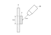
図3は、実験1における還元電極3と送風機20との関係を模式的に示す図である。
図3は、実験1における還元電極3と送風機20との関係を模式的に示す図である。
実験1では、送風機20からの二酸化炭素の噴射が還元電極3に垂直に当たるように送風機20を配置した。図3に示すように送風機20の先端と還元電極3との間を2cmに設定した。
そして、二酸化炭素の供給圧力は1.0MPaとし、1分周期で5秒間、二酸化炭素を噴射させた。この二酸化炭素の噴射によって、還元反応で還元電極3の表面に生成される液体(液滴)を除去することができる。
図4は、実験1の実験結果を示す。図4の横軸は試験時間(還元時間)、縦軸はギ酸のファラデー効率(%)である。□は送風機20の動作ありの場合のプロット、×は比較例の送風機20なしの場合のプロットである。
図4に示すように、試験時間6時間で約21%あったファラデー効率は、送風機20なしの場合は試験時間24時間で約18%に低下する。一方、本実施形態によれば、試験時間24時間のファラデー効率は約20%であり、ファラデー効率の低下を改善(-3%→-1%)できていることが分かる。
なお、送風機20と還元電極3との位置関係は、図3に示した例に限定されない。例えば図5と図6に示すように、送風機20を配置させても良い。
還元電極3をZ方向に立てて配置した場合は、図5及び図6に示すように還元電極3の上端よりも上に送風機20を配置すると良い。還元電極3の表面に生成された液体(還元生成物)は、重力によって下方に降下する。よって、上方から二酸化炭素を噴射することで、液体のその移動を促し、液体の還元電極3の表面への再付着を防止することができる。
(実験2)
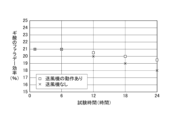
実験2は、図1に示した構成の送風機10を用いて二酸化炭素還元反応のファラデー効率を求めた。
実験2は、図1に示した構成の送風機10を用いて二酸化炭素還元反応のファラデー効率を求めた。
送風機10は、プロペラファン(タイムリー社製、LittleFAN40U)を用いた。プロペラファンは、5000rpmで回転させた。よって、送風機10で生じさせた二酸化炭素の流れは常に還元電極3の表面に当たることになる。
図7は、実験2の実験結果を示す。図7の横軸と縦軸の関係は図4と同じである。
図7に示すように、送風機10ありの場合(□)、ファラデー効率の低下を改善できていることが分かる。
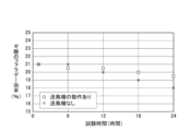
(実験3)
実験3は、実験1と同じ送風機20を用いた。そして、二酸化炭素の供給圧力は0.5MPaとし、流量5ml/minを55秒間、流量500ml/minを5秒間の組を繰り返すようにマスフローコントローラを制御した。
実験3は、実験1と同じ送風機20を用いた。そして、二酸化炭素の供給圧力は0.5MPaとし、流量5ml/minを55秒間、流量500ml/minを5秒間の組を繰り返すようにマスフローコントローラを制御した。
図8は、実験3の実験結果を示す。図8の横軸と縦軸の関係は図4及び図7と同じである。
図8に示すように、送風機20ありの場合(□)、ファラデー効率の低下を改善できていることが分かる。
以上説明したように、送風機10,20を備えることで反応効率の低下を改善できることが分かる。
本発明は、上記の実施形態に限定されるものではなく、その要旨の範囲内で変形が可能である。例えば、実施形態では光13をキセノンランプで生じさせたが、太陽光を用いてもよい。
また、電解質膜4と還元電極3は、一体で構成しても良い。電解質膜4と還元電極3を、多孔性部材と触媒から構成されるガス拡散電極(GDE(登録商標))に置き換えてもよい。部品点数を削減することができる。なお、多孔体の銅に電解質膜4を圧入して電解質膜4と還元電極3を一体化させても良い。
また、送風機10,20は、供給口9の前に配置する例を示して説明したが、送風機10,20は供給口8の前に配置しても構わない。
このように、本発明はここでは記載していない様々な実施形態等を含むことは勿論である。したがって、本発明の技術的範囲は上記の説明から妥当な特許請求の範囲に係る発明特定事項によってのみ定められるものである。
本発明は、二酸化炭素の再資源化に関する分野に広く利用することができる。
1:基板
2:酸化電極
3:還元電極
4:電解質膜
5:電解液
6:酸化槽
7:還元部
8,9:供給口
10,20:送風機
11:気体回収口
12:液体回収口
13:光
2:酸化電極
3:還元電極
4:電解質膜
5:電解液
6:酸化槽
7:還元部
8,9:供給口
10,20:送風機
11:気体回収口
12:液体回収口
13:光
Claims (7)
- 外部からの光を受光する酸化電極と、
前記酸化電極が浸漬される電解液を保持する酸化槽と、
前記酸化槽の前記光が入射する面を除いた一面の一部を構成する電解質膜と、
前記電解質膜の外側の面に接続される還元電極と、
前記還元電極が配置され外部から二酸化炭素を含む気体が供給される還元部と、
前記還元部の内部に前記還元電極に向けた気流を生じさせる送風機と
を備える二酸化炭素還元装置。 - 前記還元電極は、
板状であり、該還元電極の一方の面は前記電解質膜に接する
請求項1に記載の二酸化炭素還元装置。 - 前記送風機は、
加圧された気体が供給される供給口の内側の前方に設けられたプロペラファンで構成される
請求項1又は2に記載の二酸化炭素還元装置。 - 前記送風機は、
加圧された気体が供給される供給口の内側の先端部分に設けられたマスフローコントローラで構成される
請求項1又は2に記載の二酸化炭素還元装置。 - 前記送風機は、
間欠的に動作する
請求項3又は4に記載の二酸化炭素還元装置。 - 前記送風機は、
前記気流の流量を変化させる
請求項3乃至5の何れかに記載の二酸化炭素還元装置。 - 前記電解質膜と前記還元電極は、一体で構成される
請求項1乃至6の何れかに記載の二酸化炭素還元装置。
Priority Applications (1)
| Application Number | Priority Date | Filing Date | Title |
|---|---|---|---|
| PCT/JP2021/040551 WO2023079612A1 (ja) | 2021-11-04 | 2021-11-04 | 二酸化炭素還元装置 |
Applications Claiming Priority (1)
| Application Number | Priority Date | Filing Date | Title |
|---|---|---|---|
| PCT/JP2021/040551 WO2023079612A1 (ja) | 2021-11-04 | 2021-11-04 | 二酸化炭素還元装置 |
Publications (1)
| Publication Number | Publication Date |
|---|---|
| WO2023079612A1 true WO2023079612A1 (ja) | 2023-05-11 |
Family
ID=86240770
Family Applications (1)
| Application Number | Title | Priority Date | Filing Date |
|---|---|---|---|
| PCT/JP2021/040551 WO2023079612A1 (ja) | 2021-11-04 | 2021-11-04 | 二酸化炭素還元装置 |
Country Status (1)
| Country | Link |
|---|---|
| WO (1) | WO2023079612A1 (ja) |
Citations (5)
| Publication number | Priority date | Publication date | Assignee | Title |
|---|---|---|---|---|
| JP2006225218A (ja) * | 2005-02-21 | 2006-08-31 | Teijin Pharma Ltd | 電気化学的酸素発生素子 |
| WO2012128148A1 (ja) * | 2011-03-18 | 2012-09-27 | 国立大学法人長岡技術科学大学 | 二酸化炭素の還元固定化システム、二酸化炭素の還元固定化方法、及び有用炭素資源の製造方法 |
| JP2020023726A (ja) * | 2018-08-06 | 2020-02-13 | 富士通株式会社 | 二酸化炭素還元用電極、及び二酸化炭素還元装置 |
| WO2020121556A1 (ja) * | 2018-12-10 | 2020-06-18 | 日本電信電話株式会社 | 二酸化炭素の気相還元装置及び二酸化炭素の気相還元方法 |
| JP2021059760A (ja) * | 2019-10-08 | 2021-04-15 | 株式会社豊田中央研究所 | Co2還元反応装置 |
-
2021
- 2021-11-04 WO PCT/JP2021/040551 patent/WO2023079612A1/ja unknown
Patent Citations (5)
| Publication number | Priority date | Publication date | Assignee | Title |
|---|---|---|---|---|
| JP2006225218A (ja) * | 2005-02-21 | 2006-08-31 | Teijin Pharma Ltd | 電気化学的酸素発生素子 |
| WO2012128148A1 (ja) * | 2011-03-18 | 2012-09-27 | 国立大学法人長岡技術科学大学 | 二酸化炭素の還元固定化システム、二酸化炭素の還元固定化方法、及び有用炭素資源の製造方法 |
| JP2020023726A (ja) * | 2018-08-06 | 2020-02-13 | 富士通株式会社 | 二酸化炭素還元用電極、及び二酸化炭素還元装置 |
| WO2020121556A1 (ja) * | 2018-12-10 | 2020-06-18 | 日本電信電話株式会社 | 二酸化炭素の気相還元装置及び二酸化炭素の気相還元方法 |
| JP2021059760A (ja) * | 2019-10-08 | 2021-04-15 | 株式会社豊田中央研究所 | Co2還元反応装置 |
Similar Documents
| Publication | Publication Date | Title |
|---|---|---|
| Pawar et al. | General review on the components and parameters of photoelectrochemical system for CO2 reduction with in situ analysis | |
| Wang et al. | Efficient solar-driven electrocatalytic CO2 reduction in a redox-medium-assisted system | |
| Gao et al. | Solar water splitting with perovskite/silicon tandem cell and TiC-supported Pt nanocluster electrocatalyst | |
| Ding et al. | Photocathode engineering for efficient photoelectrochemical CO2 reduction | |
| Álvarez et al. | CO2 activation over catalytic surfaces | |
| Kalamaras et al. | Solar carbon fuel via photoelectrochemistry | |
| Hisatomi et al. | Introductory lecture: sunlight-driven water splitting and carbon dioxide reduction by heterogeneous semiconductor systems as key processes in artificial photosynthesis | |
| Shen et al. | High-yield and selective photoelectrocatalytic reduction of CO2 to formate by metallic copper decorated Co3O4 nanotube arrays | |
| Fabian et al. | Particle suspension reactors and materials for solar-driven water splitting | |
| Rongé et al. | Monolithic cells for solar fuels | |
| CN112593251B (zh) | 电化学反应装置 | |
| Walter et al. | Solar water splitting cells | |
| JP5753641B2 (ja) | 二酸化炭素還元装置および二酸化炭素を還元する方法 | |
| US20130092549A1 (en) | Proton exchange membrane electrolysis using water vapor as a feedstock | |
| CN102284293A (zh) | 用于催化还原CO2为有机燃料的Cu/Cu2O薄膜材料 | |
| JPWO2012137240A1 (ja) | 半導体素子 | |
| JP2021147679A (ja) | 二酸化炭素反応装置 | |
| Genovese et al. | A gas-phase electrochemical reactor for carbon dioxide reduction back to liquid fuels | |
| Sultan et al. | Innovative strategies toward challenges in PV-powered electrochemical CO2 reduction | |
| WO2019225494A1 (ja) | 二酸化炭素還元装置 | |
| Vanka et al. | Long-term stability metrics of photoelectrochemical water splitting | |
| JP2018090838A (ja) | 二酸化炭素還元装置 | |
| WO2023079612A1 (ja) | 二酸化炭素還元装置 | |
| JP2015004112A (ja) | 電解合成装置 | |
| JP2019203163A (ja) | 電解還元装置及び電解還元方法 |
Legal Events
| Date | Code | Title | Description |
|---|---|---|---|
| 121 | Ep: the epo has been informed by wipo that ep was designated in this application |
Ref document number: 21963209 Country of ref document: EP Kind code of ref document: A1 |
|
| ENP | Entry into the national phase |
Ref document number: 2023557880 Country of ref document: JP Kind code of ref document: A |