WO2023074737A1 - 多孔体および多孔体の製造方法 - Google Patents
多孔体および多孔体の製造方法 Download PDFInfo
- Publication number
- WO2023074737A1 WO2023074737A1 PCT/JP2022/039917 JP2022039917W WO2023074737A1 WO 2023074737 A1 WO2023074737 A1 WO 2023074737A1 JP 2022039917 W JP2022039917 W JP 2022039917W WO 2023074737 A1 WO2023074737 A1 WO 2023074737A1
- Authority
- WO
- WIPO (PCT)
- Prior art keywords
- lcp
- porous body
- liquid crystal
- crystal polymer
- powder
- Prior art date
Links
- 239000011148 porous material Substances 0.000 title claims abstract description 32
- 238000004519 manufacturing process Methods 0.000 title claims description 26
- 229920000106 Liquid crystal polymer Polymers 0.000 claims abstract description 259
- 239000004977 Liquid-crystal polymers (LCPs) Substances 0.000 claims abstract description 255
- 239000000843 powder Substances 0.000 claims abstract description 113
- 239000002245 particle Substances 0.000 claims abstract description 47
- 238000000034 method Methods 0.000 claims abstract description 39
- QSHDDOUJBYECFT-UHFFFAOYSA-N mercury Chemical compound [Hg] QSHDDOUJBYECFT-UHFFFAOYSA-N 0.000 claims abstract description 7
- 229910052753 mercury Inorganic materials 0.000 claims abstract description 7
- 239000000835 fiber Substances 0.000 claims description 79
- 239000000203 mixture Substances 0.000 claims description 44
- 238000010438 heat treatment Methods 0.000 claims description 43
- 239000011347 resin Substances 0.000 claims description 36
- 229920005989 resin Polymers 0.000 claims description 36
- 239000002612 dispersion medium Substances 0.000 claims description 26
- 239000000654 additive Substances 0.000 claims description 23
- 238000002844 melting Methods 0.000 claims description 17
- 230000008018 melting Effects 0.000 claims description 17
- 230000000996 additive effect Effects 0.000 claims description 16
- 239000011230 binding agent Substances 0.000 claims description 16
- 238000001035 drying Methods 0.000 claims description 16
- 239000000463 material Substances 0.000 claims description 15
- 238000000576 coating method Methods 0.000 claims description 9
- 229920001343 polytetrafluoroethylene Polymers 0.000 claims description 8
- 239000004810 polytetrafluoroethylene Substances 0.000 claims description 8
- -1 polytetrafluoroethylene Polymers 0.000 claims description 6
- 238000007731 hot pressing Methods 0.000 claims description 5
- 238000002459 porosimetry Methods 0.000 claims description 5
- 239000011248 coating agent Substances 0.000 claims description 3
- 150000004767 nitrides Chemical class 0.000 claims description 3
- LFQSCWFLJHTTHZ-UHFFFAOYSA-N Ethanol Chemical compound CCO LFQSCWFLJHTTHZ-UHFFFAOYSA-N 0.000 description 34
- RYGMFSIKBFXOCR-UHFFFAOYSA-N Copper Chemical compound [Cu] RYGMFSIKBFXOCR-UHFFFAOYSA-N 0.000 description 24
- IJGRMHOSHXDMSA-UHFFFAOYSA-N Atomic nitrogen Chemical compound N#N IJGRMHOSHXDMSA-UHFFFAOYSA-N 0.000 description 22
- 239000002994 raw material Substances 0.000 description 22
- 239000011889 copper foil Substances 0.000 description 21
- 239000010408 film Substances 0.000 description 19
- 238000010298 pulverizing process Methods 0.000 description 18
- 230000000052 comparative effect Effects 0.000 description 15
- XLYOFNOQVPJJNP-UHFFFAOYSA-N water Substances O XLYOFNOQVPJJNP-UHFFFAOYSA-N 0.000 description 15
- 238000012360 testing method Methods 0.000 description 14
- 239000002002 slurry Substances 0.000 description 13
- FJKROLUGYXJWQN-UHFFFAOYSA-N 4-hydroxybenzoic acid Chemical compound OC(=O)C1=CC=C(O)C=C1 FJKROLUGYXJWQN-UHFFFAOYSA-N 0.000 description 12
- 239000011362 coarse particle Substances 0.000 description 11
- 229910052757 nitrogen Inorganic materials 0.000 description 11
- 239000002131 composite material Substances 0.000 description 9
- 239000007788 liquid Substances 0.000 description 9
- 238000002156 mixing Methods 0.000 description 9
- 239000007864 aqueous solution Substances 0.000 description 8
- 239000004745 nonwoven fabric Substances 0.000 description 8
- 230000035699 permeability Effects 0.000 description 8
- 239000011324 bead Substances 0.000 description 7
- 239000006185 dispersion Substances 0.000 description 7
- 238000009826 distribution Methods 0.000 description 7
- 238000005259 measurement Methods 0.000 description 7
- 235000011837 pasties Nutrition 0.000 description 7
- 239000008188 pellet Substances 0.000 description 7
- 229940090248 4-hydroxybenzoic acid Drugs 0.000 description 6
- CDQSJQSWAWPGKG-UHFFFAOYSA-N butane-1,1-diol Chemical compound CCCC(O)O CDQSJQSWAWPGKG-UHFFFAOYSA-N 0.000 description 6
- 230000017525 heat dissipation Effects 0.000 description 6
- 229910052582 BN Inorganic materials 0.000 description 5
- PZNSFCLAULLKQX-UHFFFAOYSA-N Boron nitride Chemical compound N#B PZNSFCLAULLKQX-UHFFFAOYSA-N 0.000 description 5
- 229920001577 copolymer Polymers 0.000 description 5
- 239000011521 glass Substances 0.000 description 5
- 239000004925 Acrylic resin Substances 0.000 description 4
- 229920000178 Acrylic resin Polymers 0.000 description 4
- KKEYFWRCBNTPAC-UHFFFAOYSA-N Terephthalic acid Chemical compound OC(=O)C1=CC=C(C(O)=O)C=C1 KKEYFWRCBNTPAC-UHFFFAOYSA-N 0.000 description 4
- 238000001914 filtration Methods 0.000 description 4
- ZWEHNKRNPOVVGH-UHFFFAOYSA-N 2-Butanone Chemical compound CCC(C)=O ZWEHNKRNPOVVGH-UHFFFAOYSA-N 0.000 description 3
- JCJUKCIXTRWAQY-UHFFFAOYSA-N 6-hydroxynaphthalene-1-carboxylic acid Chemical compound OC1=CC=C2C(C(=O)O)=CC=CC2=C1 JCJUKCIXTRWAQY-UHFFFAOYSA-N 0.000 description 3
- CSCPPACGZOOCGX-UHFFFAOYSA-N Acetone Chemical compound CC(C)=O CSCPPACGZOOCGX-UHFFFAOYSA-N 0.000 description 3
- UHOVQNZJYSORNB-UHFFFAOYSA-N Benzene Chemical compound C1=CC=CC=C1 UHOVQNZJYSORNB-UHFFFAOYSA-N 0.000 description 3
- RTZKZFJDLAIYFH-UHFFFAOYSA-N Diethyl ether Chemical compound CCOCC RTZKZFJDLAIYFH-UHFFFAOYSA-N 0.000 description 3
- KFZMGEQAYNKOFK-UHFFFAOYSA-N Isopropanol Chemical compound CC(C)O KFZMGEQAYNKOFK-UHFFFAOYSA-N 0.000 description 3
- OKKJLVBELUTLKV-UHFFFAOYSA-N Methanol Chemical compound OC OKKJLVBELUTLKV-UHFFFAOYSA-N 0.000 description 3
- 239000004974 Thermotropic liquid crystal Substances 0.000 description 3
- YXFVVABEGXRONW-UHFFFAOYSA-N Toluene Chemical compound CC1=CC=CC=C1 YXFVVABEGXRONW-UHFFFAOYSA-N 0.000 description 3
- 230000001186 cumulative effect Effects 0.000 description 3
- 230000007423 decrease Effects 0.000 description 3
- 229910052751 metal Inorganic materials 0.000 description 3
- 239000002184 metal Substances 0.000 description 3
- 229920000728 polyester Polymers 0.000 description 3
- 238000000790 scattering method Methods 0.000 description 3
- 229920000049 Carbon (fiber) Polymers 0.000 description 2
- LCGLNKUTAGEVQW-UHFFFAOYSA-N Dimethyl ether Chemical compound COC LCGLNKUTAGEVQW-UHFFFAOYSA-N 0.000 description 2
- 229920001410 Microfiber Polymers 0.000 description 2
- 239000004813 Perfluoroalkoxy alkane Substances 0.000 description 2
- ISWSIDIOOBJBQZ-UHFFFAOYSA-N Phenol Chemical compound OC1=CC=CC=C1 ISWSIDIOOBJBQZ-UHFFFAOYSA-N 0.000 description 2
- MCMNRKCIXSYSNV-UHFFFAOYSA-N Zirconium dioxide Chemical compound O=[Zr]=O MCMNRKCIXSYSNV-UHFFFAOYSA-N 0.000 description 2
- 239000000853 adhesive Substances 0.000 description 2
- 230000001070 adhesive effect Effects 0.000 description 2
- 239000004917 carbon fiber Substances 0.000 description 2
- 239000004744 fabric Substances 0.000 description 2
- 239000000945 filler Substances 0.000 description 2
- 238000000227 grinding Methods 0.000 description 2
- 239000011261 inert gas Substances 0.000 description 2
- 239000004750 melt-blown nonwoven Substances 0.000 description 2
- VNWKTOKETHGBQD-UHFFFAOYSA-N methane Chemical compound C VNWKTOKETHGBQD-UHFFFAOYSA-N 0.000 description 2
- 239000003658 microfiber Substances 0.000 description 2
- VLKZOEOYAKHREP-UHFFFAOYSA-N n-Hexane Chemical compound CCCCCC VLKZOEOYAKHREP-UHFFFAOYSA-N 0.000 description 2
- 229920011301 perfluoro alkoxyl alkane Polymers 0.000 description 2
- 239000012466 permeate Substances 0.000 description 2
- 238000005191 phase separation Methods 0.000 description 2
- 238000001179 sorption measurement Methods 0.000 description 2
- 229910001220 stainless steel Inorganic materials 0.000 description 2
- 239000010935 stainless steel Substances 0.000 description 2
- 239000000758 substrate Substances 0.000 description 2
- LLLVZDVNHNWSDS-UHFFFAOYSA-N 4-methylidene-3,5-dioxabicyclo[5.2.2]undeca-1(9),7,10-triene-2,6-dione Chemical compound C1(C2=CC=C(C(=O)OC(=C)O1)C=C2)=O LLLVZDVNHNWSDS-UHFFFAOYSA-N 0.000 description 1
- OKTJSMMVPCPJKN-UHFFFAOYSA-N Carbon Chemical compound [C] OKTJSMMVPCPJKN-UHFFFAOYSA-N 0.000 description 1
- 239000001856 Ethyl cellulose Substances 0.000 description 1
- ZZSNKZQZMQGXPY-UHFFFAOYSA-N Ethyl cellulose Chemical compound CCOCC1OC(OC)C(OCC)C(OCC)C1OC1C(O)C(O)C(OC)C(CO)O1 ZZSNKZQZMQGXPY-UHFFFAOYSA-N 0.000 description 1
- CTQNGGLPUBDAKN-UHFFFAOYSA-N O-Xylene Chemical compound CC1=CC=CC=C1C CTQNGGLPUBDAKN-UHFFFAOYSA-N 0.000 description 1
- 229910052581 Si3N4 Inorganic materials 0.000 description 1
- 238000010521 absorption reaction Methods 0.000 description 1
- WUOACPNHFRMFPN-UHFFFAOYSA-N alpha-terpineol Chemical compound CC1=CCC(C(C)(C)O)CC1 WUOACPNHFRMFPN-UHFFFAOYSA-N 0.000 description 1
- 125000003118 aryl group Chemical group 0.000 description 1
- VCCBEIPGXKNHFW-UHFFFAOYSA-N biphenyl-4,4'-diol Chemical group C1=CC(O)=CC=C1C1=CC=C(O)C=C1 VCCBEIPGXKNHFW-UHFFFAOYSA-N 0.000 description 1
- 229910052802 copper Inorganic materials 0.000 description 1
- 239000010949 copper Substances 0.000 description 1
- PMHQVHHXPFUNSP-UHFFFAOYSA-M copper(1+);methylsulfanylmethane;bromide Chemical compound Br[Cu].CSC PMHQVHHXPFUNSP-UHFFFAOYSA-M 0.000 description 1
- 238000005520 cutting process Methods 0.000 description 1
- 230000006378 damage Effects 0.000 description 1
- 238000013480 data collection Methods 0.000 description 1
- SQIFACVGCPWBQZ-UHFFFAOYSA-N delta-terpineol Natural products CC(C)(O)C1CCC(=C)CC1 SQIFACVGCPWBQZ-UHFFFAOYSA-N 0.000 description 1
- 230000001419 dependent effect Effects 0.000 description 1
- IMHDGJOMLMDPJN-UHFFFAOYSA-N dihydroxybiphenyl Natural products OC1=CC=CC=C1C1=CC=CC=C1O IMHDGJOMLMDPJN-UHFFFAOYSA-N 0.000 description 1
- JVSWJIKNEAIKJW-UHFFFAOYSA-N dimethyl-hexane Natural products CCCCCC(C)C JVSWJIKNEAIKJW-UHFFFAOYSA-N 0.000 description 1
- 229920001249 ethyl cellulose Polymers 0.000 description 1
- 235000019325 ethyl cellulose Nutrition 0.000 description 1
- 239000011888 foil Substances 0.000 description 1
- 230000004927 fusion Effects 0.000 description 1
- 229920006015 heat resistant resin Polymers 0.000 description 1
- 239000011256 inorganic filler Substances 0.000 description 1
- 229910003475 inorganic filler Inorganic materials 0.000 description 1
- 230000001788 irregular Effects 0.000 description 1
- 239000000155 melt Substances 0.000 description 1
- 238000002074 melt spinning Methods 0.000 description 1
- 239000012046 mixed solvent Substances 0.000 description 1
- 239000000178 monomer Substances 0.000 description 1
- 239000003921 oil Substances 0.000 description 1
- 229920002037 poly(vinyl butyral) polymer Polymers 0.000 description 1
- 229920001721 polyimide Polymers 0.000 description 1
- 239000002861 polymer material Substances 0.000 description 1
- 238000012545 processing Methods 0.000 description 1
- 239000000047 product Substances 0.000 description 1
- 230000001737 promoting effect Effects 0.000 description 1
- 239000012779 reinforcing material Substances 0.000 description 1
- 238000001878 scanning electron micrograph Methods 0.000 description 1
- 238000007873 sieving Methods 0.000 description 1
- HQVNEWCFYHHQES-UHFFFAOYSA-N silicon nitride Chemical compound N12[Si]34N5[Si]62N3[Si]51N64 HQVNEWCFYHHQES-UHFFFAOYSA-N 0.000 description 1
- 239000002904 solvent Substances 0.000 description 1
- 239000007921 spray Substances 0.000 description 1
- 229940116411 terpineol Drugs 0.000 description 1
- 238000010998 test method Methods 0.000 description 1
- 238000009210 therapy by ultrasound Methods 0.000 description 1
- 238000001931 thermography Methods 0.000 description 1
- 239000011800 void material Substances 0.000 description 1
- 239000002759 woven fabric Substances 0.000 description 1
- 239000008096 xylene Substances 0.000 description 1
Images


Classifications
-
- B—PERFORMING OPERATIONS; TRANSPORTING
- B01—PHYSICAL OR CHEMICAL PROCESSES OR APPARATUS IN GENERAL
- B01D—SEPARATION
- B01D39/00—Filtering material for liquid or gaseous fluids
- B01D39/14—Other self-supporting filtering material ; Other filtering material
- B01D39/16—Other self-supporting filtering material ; Other filtering material of organic material, e.g. synthetic fibres
-
- C—CHEMISTRY; METALLURGY
- C08—ORGANIC MACROMOLECULAR COMPOUNDS; THEIR PREPARATION OR CHEMICAL WORKING-UP; COMPOSITIONS BASED THEREON
- C08J—WORKING-UP; GENERAL PROCESSES OF COMPOUNDING; AFTER-TREATMENT NOT COVERED BY SUBCLASSES C08B, C08C, C08F, C08G or C08H
- C08J9/00—Working-up of macromolecular substances to porous or cellular articles or materials; After-treatment thereof
- C08J9/28—Working-up of macromolecular substances to porous or cellular articles or materials; After-treatment thereof by elimination of a liquid phase from a macromolecular composition or article, e.g. drying of coagulum
-
- D—TEXTILES; PAPER
- D04—BRAIDING; LACE-MAKING; KNITTING; TRIMMINGS; NON-WOVEN FABRICS
- D04H—MAKING TEXTILE FABRICS, e.g. FROM FIBRES OR FILAMENTARY MATERIAL; FABRICS MADE BY SUCH PROCESSES OR APPARATUS, e.g. FELTS, NON-WOVEN FABRICS; COTTON-WOOL; WADDING ; NON-WOVEN FABRICS FROM STAPLE FIBRES, FILAMENTS OR YARNS, BONDED WITH AT LEAST ONE WEB-LIKE MATERIAL DURING THEIR CONSOLIDATION
- D04H1/00—Non-woven fabrics formed wholly or mainly of staple fibres or like relatively short fibres
- D04H1/40—Non-woven fabrics formed wholly or mainly of staple fibres or like relatively short fibres from fleeces or layers composed of fibres without existing or potential cohesive properties
- D04H1/42—Non-woven fabrics formed wholly or mainly of staple fibres or like relatively short fibres from fleeces or layers composed of fibres without existing or potential cohesive properties characterised by the use of certain kinds of fibres insofar as this use has no preponderant influence on the consolidation of the fleece
- D04H1/4382—Stretched reticular film fibres; Composite fibres; Mixed fibres; Ultrafine fibres; Fibres for artificial leather
-
- D—TEXTILES; PAPER
- D04—BRAIDING; LACE-MAKING; KNITTING; TRIMMINGS; NON-WOVEN FABRICS
- D04H—MAKING TEXTILE FABRICS, e.g. FROM FIBRES OR FILAMENTARY MATERIAL; FABRICS MADE BY SUCH PROCESSES OR APPARATUS, e.g. FELTS, NON-WOVEN FABRICS; COTTON-WOOL; WADDING ; NON-WOVEN FABRICS FROM STAPLE FIBRES, FILAMENTS OR YARNS, BONDED WITH AT LEAST ONE WEB-LIKE MATERIAL DURING THEIR CONSOLIDATION
- D04H13/00—Other non-woven fabrics
-
- D—TEXTILES; PAPER
- D21—PAPER-MAKING; PRODUCTION OF CELLULOSE
- D21H—PULP COMPOSITIONS; PREPARATION THEREOF NOT COVERED BY SUBCLASSES D21C OR D21D; IMPREGNATING OR COATING OF PAPER; TREATMENT OF FINISHED PAPER NOT COVERED BY CLASS B31 OR SUBCLASS D21G; PAPER NOT OTHERWISE PROVIDED FOR
- D21H13/00—Pulp or paper, comprising synthetic cellulose or non-cellulose fibres or web-forming material
- D21H13/10—Organic non-cellulose fibres
- D21H13/20—Organic non-cellulose fibres from macromolecular compounds obtained otherwise than by reactions only involving carbon-to-carbon unsaturated bonds
- D21H13/24—Polyesters
Definitions
- the present invention relates to a porous body and a method for manufacturing a porous body.
- porous polymer materials include fiber-based nonwoven fabrics and porous films based on film manufacturing methods (Patent Documents 1 to 7). Also, when forming a polymeric porous body using a liquid crystal polymer (LCP), even if a non-woven fabric is formed from fibers obtained by a general melt spinning method, only a porous body with coarse fiber diameters and large pores can be obtained. Therefore, in order to obtain a porous body having fine pores, it is necessary to use fine fiber LCP.
- LCP liquid crystal polymer
- Examples of methods for forming a nonwoven fabric using LCP of fine fibers include the papermaking method and the meltblowing method.
- Methods for forming a porous film include, for example, a method of stretching an LCP film containing a filler, a phase separation method, and the like.
- the present disclosure aims to provide a strong porous body using LCP of fine fibers.
- the porous body of the present disclosure is A porous body containing liquid crystal polymer powder,
- the liquid crystal polymer powder contains fibrous particles made of a liquid crystal polymer,
- the fibrous particles made of the liquid crystal polymer have an average diameter of 2 ⁇ m or less, Having an average pore diameter of 10 ⁇ m or less measured by mercury porosimetry, It has a tensile strength of 25 N/mm 2 or more.
- FIG. 1 is a graph showing the relationship between heating temperature and tensile strength in the heating process for Examples 1 to 3 and Comparative Example 1.
- FIG. 2 is a graph showing the relationship between heating temperature and tensile strength in the heating process for Examples 4 to 6 and Comparative Example 2.
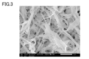
- FIG. 3 is a photograph of a cross section of the porous body in Example 1.
- FIG. 4 is a photograph of a cross section of the porous body in Example 2.
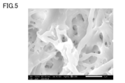
- FIG. 5 is a photograph of a cross section of the porous body in Example 3.
- FIG. 6 is a photograph of a cross section of the porous body in Comparative Example 1.
- FIG. 7 is a photograph of a cross section of the porous body in Reference Example 1.
- FIG. 8 is a photograph of a cross section of the porous body in Example 7.
- FIG. 9 is a flowchart showing steps for manufacturing the porous body of Embodiment 1.
- FIG. 10 is a flowchart showing steps for manufacturing a porous body according to Embodiment
- the porous body according to the present embodiment contains liquid crystal polymer powder (LCP powder), the liquid crystal polymer powder contains fibrous particles (liquid crystal polymer fiber: LCP fiber) made of liquid crystal polymer, and the average diameter of the LCP fiber is , 2 ⁇ m or less.
- the porous body has an average pore diameter of 10 ⁇ m or less measured by mercury porosimetry and a tensile strength of 25 N/mm 2 or more.
- thermotropic liquid crystal polymers are, for example, an aromatic polyester synthesized mainly from monomers such as aromatic diols, aromatic dicarboxylic acids, and aromatic hydroxycarboxylic acids, and exhibits liquid crystallinity when melted.
- Liquid crystal polymer molecules have a negative coefficient of linear expansion (CTE) in the axial direction of the molecular axis and a positive CTE in the radial direction of the molecular axis.
- CTE negative coefficient of linear expansion
- the liquid crystal polymer does not have an amide bond.
- a thermotropic liquid crystal polymer having no amide bond for example, a copolymer of parahydroxybenzoic acid, terephthalic acid, and dihydroxybiphenyl with a high melting point and a low CTE called a type 1 liquid crystal polymer (parahydroxybenzoic acid and ethylene terephthalate), or parahydroxybenzoic acid and 2,6-hydroxynaphthoic acid, which have a melting point between type 1 and type 2 liquid crystalline polymers, called type 1.5 (or type 3) and copolymers.
- the LCP fiber contained in the LCP powder is not particularly limited as long as it contains a fibrous portion.
- the fibrous portion may be linear or branched.
- the average diameter of LCP fibers is 2 ⁇ m or less, preferably 1 ⁇ m or less. Also, the average aspect ratio of the LCP fiber is preferably 10 or more and 500 or less, more preferably 10 or more and 300 or less.
- the average diameter and average aspect ratio of LCP fibers are measured by the following methods.
- LCP powder composed of LCP fibers to be measured is dispersed in ethanol to prepare a slurry in which 0.01% by mass of LCP powder is dispersed. At this time, the slurry is prepared so that the water content in the slurry is 1% by mass or less. Then, after dropping 5 to 10 ⁇ L of this slurry onto a slide glass, the slurry on the slide glass is naturally dried. The LCP powder is placed on the glass slide by allowing the slurry to air dry. Next, by observing a predetermined region of the LCP powder placed on the slide glass with a scanning electron microscope (SEM), 100 or more image data of particles (LCP fibers) constituting the LCP powder are collected.
- SEM scanning electron microscope
- the area is set according to the size of one particle of the LCP so that the number of image data is 100 or more.
- the magnification of the SEM is changed to 500 times, 3000 times, or 10000 times as appropriate, and the image data is collected. do.
- the longitudinal dimension and the width dimension of each of the LCP fibers are measured using the image data collected above. In one LCP fiber photographed in each of the above image data, the longest route among the routes from one end to the end opposite to the one end through the approximate center of the particle defined as the longitudinal direction. Then, the length of the straight line connecting both ends of the longest path is measured as the longitudinal dimension.
- the dimension of the particle in the direction orthogonal to the longitudinal direction is measured at three different points in the longitudinal direction of one particle of the LCP powder.
- the average value of the dimensions measured at these three points is taken as the width direction dimension (fiber diameter) per particle of the LCP powder.
- the ratio of the longitudinal dimension to the fiber diameter [longitudinal dimension/fiber diameter] is calculated as the aspect ratio of the LCP fiber.
- the average value of the fiber diameters measured for 100 LCP fibers is taken as the average diameter.
- the average value of the aspect ratios measured for 100 LCP fibers is taken as the average aspect ratio.
- the fibrous particles may be contained in the LCP powder as aggregates of fibrous particles.
- the axial direction of the LCP molecules constituting the fibrous particles and the longitudinal direction of the fibrous particles tend to coincide with each other.
- LCP powder is produced, a plurality of domains formed by bundles of LCP molecules are broken so that the axial direction of the LCP molecules is along the longitudinal direction of the fibrous particles. This is thought to be due to the orientation of the
- the content (number ratio) of particles other than fibrous particles is 20% or less.
- particles having a maximum height of 10 ⁇ m or less when the LCP powder is placed on a flat surface are fibrous particles, and particles having a maximum height of more than 10 ⁇ m are aggregate particles.
- the LCP powder preferably has a D50 (average particle diameter) value of 13 ⁇ m or less as measured by particle size measurement using a particle size distribution measuring device based on a laser diffraction scattering method.
- the porous body of this embodiment has an average pore diameter of 10 ⁇ m or less.
- the "average pore diameter” means a pore diameter at which the cumulative pore distribution of pore distribution measured by mercury porosimetry is 50% of the total pore volume. If the average pore diameter of the porous body exceeds 10 ⁇ m, the functions of the porous body such as filtration performance may not be sufficiently obtained.
- the average pore size of the porous body is preferably 5.0 ⁇ m or less.
- the average pore size of the porous body may be 0.1 ⁇ m or more, or may be 0.3 ⁇ m or more.
- the porous body of this embodiment has a tensile strength of 25 N/mm 2 or more.
- the tensile strength in the present embodiment refers to the load value at which the test piece is cut when a 5 mm x 25 mm test piece taken from a porous body is elongated under the conditions of a gripping distance of 13 mm and a tensile speed of 0.6 mm/min. is divided by the cross-sectional area excluding the holes (N/mm 2 ).
- the tensile strength of the porous body is preferably 40 N/mm 2 or more, more preferably 60 N/mm 2 or more.
- the porous body of the present embodiment may contain additives.
- the function of the additive such as water repellency, oil repellency, and heat dissipation, can be imparted to the porous body.
- additives include inorganic fillers, polytetrafluoroethylene (PTFE), perfluoroalkoxyalkane (PFA), fine carbon powder, fine carbon fiber, metal powder, and nitride powder.
- PTFE polytetrafluoroethylene
- PFA perfluoroalkoxyalkane
- fine carbon powder fine carbon fiber
- metal powder and nitride powder.
- nitride powder include boron nitride powder, aluminum nitride powder, and silicon nitride powder.
- the porous body of the present embodiment does not contain an adhesive that bonds LCP fibers together. This is because the porous body of the present embodiment achieves the above tensile strength by bonding LCP fibers to each other by heating. Moreover, the inclusion of an adhesive may cause problems such as a decrease in heat resistance and an increase in water absorption.
- the method for manufacturing a porous body according to the present embodiment includes a dispersing step (S1), a matting step (S2), and a heating step (S3).
- the LCP powder can be produced, for example, by performing the following coarse pulverization step, fine pulverization step, coarse particle removal step, and fiberization step in this order.
- LCP raw material examples include uniaxially oriented pellets, biaxially oriented films, and powdery LCP.
- the LCP that constitutes the LCP raw material is the same as the LCP that constitutes the LCP fiber described above.
- the LCP raw material is coarsely pulverized.
- the LCP raw material is coarsely pulverized with a cutter mill.
- the size of the coarsely pulverized LCP particles is not particularly limited as long as it can be used as a raw material for the fine pulverization step described below.
- the maximum particle size of the coarsely ground LCP particles is, for example, 3 mm or less.
- the LCP raw material can be used as a raw material for the fine grinding process
- the LCP raw material may be used directly as the raw material for the fine grinding process.
- the LCP raw material (after the coarsely pulverizing step) is pulverized while being dispersed in liquid nitrogen to obtain granular finely pulverized liquid crystal polymer (finely pulverized LCP).
- the fine pulverization step it is preferable to use media to pulverize the LCP raw material dispersed in liquid nitrogen.
- the media are beads, for example.
- a bead mill which has relatively few technical problems, from the viewpoint of handling liquid nitrogen.
- An apparatus that can be used in the pulverization step includes, for example, "LNM-08", which is a liquid nitrogen bead mill manufactured by Imex.
- the granular, pulverized LCP obtained by the pulverization step preferably has a D50 of 50 ⁇ m or less as measured by a particle size distribution measuring device using a laser diffraction scattering method. This can prevent nozzles from being clogged with particulate pulverized LCP in the fiberization step described below.
- coarse particle removal step coarse particles are removed from the granular finely pulverized LCP obtained in the finely pulverizing step. For example, by sieving the granular finely ground LCP with a mesh to obtain the granular finely ground LCP under the sieve, and removing the granular LCP on the sieve to remove the coarse particles contained in the granular finely ground LCP can be removed.
- the type of mesh may be appropriately selected, and examples of meshes include those with an opening of 53 ⁇ m. Note that it is not always necessary to perform the coarse particle removal step.
- the granular LCP is pulverized with a wet high-pressure pulverizer to obtain LCP powder.
- the finely ground LCP is dispersed in the dispersion medium for the fiberization step.
- the finely ground LCP to be dispersed may not have coarse particles removed, but it is preferred that coarse particles have been removed.
- Dispersion media for the fiberizing step include, for example, water, ethanol, methanol, isopropyl alcohol, toluene, benzene, xylene, phenol, acetone, methyl ethyl ketone, diethyl ether, dimethyl ether, hexane, or mixtures thereof.
- the finely pulverized LCP dispersed in the dispersion medium for the fiberization step that is, the paste-like or slurry-like finely pulverized LCP is passed through a nozzle while being pressurized at a high pressure.
- the shear force or collision energy due to the high-speed flow in the nozzle acts on the LCP, crushing the granular finely pulverized LCP, thereby promoting the fiberization of the LCP and forming fine LCP fibers.
- the nozzle diameter of the nozzle is preferably as small as possible within the range where clogging of the finely pulverized LCP does not occur in the nozzle. Since the particle size of the finely pulverized LCP is relatively small, it is possible to reduce the nozzle diameter of the wet high-pressure crusher used in the fiberization process.
- the nozzle diameter is, for example, 0.2 mm or less.
- the dispersion medium penetrates into the finely pulverized LCP through the fine cracks due to the pressurization by the wet high-pressure crusher. Then, when the paste-like or slurry-like finely ground LCP passes through the nozzle and is placed under normal pressure, the dispersion medium that has entered the inside of the finely ground LCP expands in a short time. Due to the expansion of the dispersion medium that has entered the finely pulverized LCP, the destruction progresses from the inside of the finely pulverized LCP.
- the granular finely pulverized LCP obtained in the finely pulverizing step of the present embodiment is fibrillated to obtain the granular LCP obtained by the conventional freeze pulverization method. It is possible to obtain an LCP powder which has a lower content of aggregated particles than LCP powder obtained by crushing LCP and which is composed of fine LCP fibers.
- LCP powder may be obtained by crushing finely pulverized LCP a plurality of times with a wet high pressure crushing device.
- the number of times of crushing by the device is preferably small, for example, 5 times or less.
- Dispersing step which is the first step of the method for producing a porous body
- the above LCP powder is dispersed in a dispersion medium to form a paste or slurry.
- the LCP powder can be dispersed in a high-viscosity dispersion medium.
- Dispersion media used in the dispersion process include butanediol, water, ethanol, terpineol, and a mixture of water and ethanol.
- butanediol is used as the dispersion medium
- paste-like LCP powder is obtained.
- slurry-like LCP powder is obtained.
- LCP powder and additive A mixture of is sometimes simply referred to as a “mixture”.
- the mixing ratio of the additive is preferably 50% by volume or less with respect to the mixture.
- the matting step is, for example, a papermaking method.
- the dispersion medium used in the dispersion process can be easily recovered and reused, and the porous body can be manufactured at low cost.
- slurry-like LCP powder or mixture is made on a mesh, a non-woven microporous sheet, or a woven fabric. Then, the LCP fiber mat is obtained by heating and drying the slurry-like LCP powder or mixture placed on the mesh.
- a pasty LCP powder or mixture may be formed into an LCP fiber mat by a coating step and a drying step.
- the paste-like LCP powder or mixture is applied to the base material.
- the “base material” refers to a material or support material for applying the paste-like LCP powder or mixture, such as metal foil such as copper foil, polyimide film, PTFE film, or carbon fiber or glass.
- a composite sheet made of a reinforcing material such as fiber and a heat-resistant resin can be used.
- the paste-like LCP powder or mixture applied to the base material is heated and dried to vaporize the dispersion medium.
- the heat drying described above forms an LCP fiber mat on the substrate.
- the dispersion medium is gradually removed from the paste-like LCP powder or mixture, so the overall thickness of the paste-like LCP powder or mixture gradually decreases during drying.
- the thickness of the LCP fiber mat is reduced compared to the overall thickness of the pasty LCP powder or mixture formed on the product.
- the longitudinal orientation of the fibrous particles in the LCP powder changes. Specifically, among fibrous particles, fibrous particles having a longitudinal direction in the thickness direction of the entire paste-like LCP powder or mixture are arranged so that the longitudinal direction is oriented in the main surface direction of the base material. , tilt. Therefore, there is anisotropy in the longitudinal direction of the fibrous particles in the formed LCP fiber mat.
- a paste-like LCP powder or mixture is further applied on the LCP fiber mat formed on the base material in the drying step, and then dried to evaporate the dispersion medium. good.
- the coating process and the drying process may be repeated in this order.
- an LCP fiber mat having a desired basis weight can be obtained.
- a mixture in which the mixing ratio of the LCP powder and the additive is changed for each coating process may be used.
- an LCP fiber mat capable of forming a porous body having desired properties can be obtained.
- Heating step S3
- the heating step the LCP fiber mat is heated to obtain a porous body.
- the heating may be performed in an inert gas atmosphere. By doing so, the tensile strength of the porous body can be further improved.
- the heating temperature in the heating process is in the range of -60°C to -5°C, which is the melting point of the LCP powder. If the heating temperature is lower than ⁇ 60° C., the melting point of the LCP powder, the adhesion between the LCP fibers is weak and a porous body having practical strength cannot be obtained. If the heating temperature is higher than the melting point of the LCP powder of ⁇ 5° C., the LCP fibers are softened and deformed, and the porous structure cannot be maintained.
- the heating temperature is preferably in the range of ⁇ 50° C. to ⁇ 10° C. of the melting point of the LCP powder, more preferably in the range of ⁇ 40° C. to ⁇ 20° C. of the melting point of the LCP powder.
- the holding time in the heating step is not particularly limited, and may be, for example, 5 minutes or longer, or 15 minutes or longer. Moreover, since a porous body having higher strength can be obtained by holding it for a long time, the holding time may be, for example, 30 minutes or longer, or 60 minutes or longer.
- the LCP fiber mat is formed on the base material by the coating process and the drying process, the LCP fiber mat is heated together with the base material.
- the porous body with the substrates bonded thereto can be obtained at a low cost.
- a paste-like LCP powder or mixture can be applied to the necessary part of the base material and dried to partially form a porous body on the base material or to form a three-dimensional porous body. can.
- the porous body of this embodiment differs from that of the first embodiment in that it has an average pore diameter of 1.0 ⁇ m or less.
- a porous body with a fine average pore diameter is considered to be excellent in strength, filtering properties, and the like.
- Other points are the same as those of the first embodiment, and redundant description is omitted.
- the method for manufacturing a porous body according to the present embodiment includes a dispersing step (S10), a matting step (S20), a hot pressing step (S30), and a heating step (S40). , provided.
- S10 dispersing step
- S20 matting step
- S30 hot pressing step
- S40 heating step
- Dispersing step S10
- the LCP powder and the binder resin are dispersed in a dispersion medium to form a paste-like or slurry-like resin mixture.
- a binder resin in the dispersing step and forming a film in the hot press step described later, it is expected to improve the handling property, such as facilitating the processing before the production of the porous body.
- binder resins used in the dispersion process include acrylic resins, butyral resins, and ethyl cellulose resins. Among these, acrylic resins are preferable from the viewpoint of degradability.
- the mixing ratio of the binder resin is preferably 30% by volume or more and 70% by volume or less with respect to the resin mixture. Also, the average diameter of the binder resin is preferably 10 ⁇ m or less.
- the LCP powder, binder resin, and additives are mixed in this step.
- the heating temperature in the hot press process is 20°C or higher and 100°C or lower. If the heating temperature is less than 20°C, the binder resin is not softened, making it difficult to form a film. When the heating temperature exceeds 100°C, the binder resin will flow.
- the heating temperature is preferably 40° C. or higher and 80° C. or lower.
- the pressure in the heat press process is 0.3 MPa or more and 3.0 MPa or less. If the pressure is less than 0.3 MPa, the pressure is insufficient and air bubbles remain. When the pressure exceeds 3.0 MPa, the binder resin will flow.
- the pressure is preferably 0.5 MPa or more and 1.0 MPa or less.
- the holding time in the hot press process is not particularly limited, and may be, for example, 1 minute or longer, or 10 minutes or longer.
- Heating step Next, in the heating step, at least part of the binder resin contained in the resin mixture film is removed by heating to obtain a porous body.
- the porous body may contain a binder resin.
- the ratio of the remaining binder resin is adjusted by the heating temperature and holding time in the heating step.
- Example 1 Manufacture of liquid crystal polymer powder
- LCP pellets cylindrical pellets with a diameter of 3 to 4 mm, melting point: 315° C.
- the material of LCP is a copolymer of parahydroxybenzoic acid and 4,6-hydroxynaphthoic acid.
- This LCP raw material was coarsely pulverized with a cutter mill (manufactured by IKA, MF10).
- Coarsely pulverized LCP was obtained by passing the coarsely pulverized LCP through a mesh with a diameter of 3 mm provided at the outlet of the cutter mill.
- the coarsely pulverized LCP was finely pulverized with a liquid nitrogen bead mill (LNM-08 manufactured by Imex, vessel capacity: 0.8 L). Specifically, 500 mL of media and 30 g of coarsely pulverized LCP were put into a vessel and pulverized for 120 minutes at a rotation speed of 2000 rpm. As media, zirconia (ZrO 2 ) beads with a diameter of 5 mm were used. In the liquid nitrogen bead mill, wet pulverization is performed in a state in which the coarsely pulverized LCP is dispersed in liquid nitrogen. Thus, by pulverizing the coarsely pulverized LCP with a liquid nitrogen bead mill, granular finely pulverized LCP was obtained.
- a liquid nitrogen bead mill liquid nitrogen bead mill
- the particle size of this finely ground LCP was measured.
- the finely pulverized LCP dispersed in the dispersion medium was subjected to ultrasonic treatment for 10 seconds, and then set in a particle size distribution measuring device (manufactured by Horiba, LA-950) using a laser diffraction scattering method. , particle size measurements were performed.
- Ekinen registered trademark, Nippon Alcohol Sales Co., Ltd.
- the measured D50 of the micronized LCP was 23 ⁇ m.
- the dispersion obtained by dispersing the finely ground LCP in Ekinene was sieved through a mesh with an opening of 53 ⁇ m to remove coarse particles contained in the finely ground LCP, and the finely ground LCP that passed through the mesh was collected.
- the yield of finely pulverized LCP by removing coarse particles was 85% by mass.
- the finely pulverized LCP from which coarse particles were removed was dispersed in a 20% by mass ethanol aqueous solution.
- the ethanol slurry in which the finely pulverized LCP was dispersed was crushed five times using a wet high-pressure crusher under conditions of a nozzle diameter of 0.2 mm and a pressure of 200 MPa to form fibers.
- a high-pressure disperser (Nanoveita manufactured by Yoshida Kikai Kogyo Co., Ltd.) was used as the wet high-pressure crusher.
- LCP powder was obtained by drying the ethanol slurry in which finely ground LCP was dispersed with a spray dryer.
- the average fiber diameter measured for 100 LCP fibers contained in the LCP powder was 0.8 ⁇ m.
- the LCP powder obtained above was dispersed in a 50% by mass ethanol aqueous solution as a dispersion medium to form a slurry.
- the slurry of LCP powder was placed on a wire mesh of 80 mesh, and a polyester microfiber nonwoven fabric (weight per unit area: 14 g/m 2 ) was placed on the paper using a rectangular sheet machine (manufactured by Kumagai Riki Kogyo Co., Ltd.). Cultivated to obtain an LCP fiber mat.
- the amount of LCP powder was adjusted so that the basis weight of the LCP fiber mat was 35 g/m 2 .
- the LCP fiber mat was dried with a hot air dryer and peeled off from the polyester microfiber nonwoven fabric to form an LCP fiber mat.
- the LCP fiber mat was placed on a stainless steel vat and heated in a hot air inert oven (inert gas oven INH-21CD manufactured by Koyo Thermo Systems Co., Ltd.). Specifically, heat treatment was performed at 260° C. for 60 minutes under a nitrogen stream. A porous body was thus obtained.
- a hot air inert oven inert gas oven INH-21CD manufactured by Koyo Thermo Systems Co., Ltd.
- Example 2 and 3 and Comparative Example 1 In Examples 2 and 3 and Comparative Example 1, the heating temperatures in the hot air inert oven were set to 270° C., 280° C. and 250° C., respectively. Otherwise, LCP powder was produced in the same manner as in Example 1 to obtain a porous body.
- Example 4 to 6 Comparative Example 2>
- uniaxially oriented LCP pellets (cylindrical pellets with a diameter of 3 to 4 mm, melting point: 340° C.) were prepared as LCP raw materials.
- the material of LCP is a copolymer of parahydroxybenzoic acid and 4,6-hydroxynaphthoic acid.
- LCP powder was prepared in the same manner as in Example 1, except that the LCP raw material was changed as described above.
- the average fiber diameter measured for 100 LCP fibers contained in the LCP powder was 0.9 ⁇ m.
- Example 4 to 6 and Comparative Example 2 the heating temperatures of the hot air inert oven were set to 280°C, 290°C, 300°C and 270°C, respectively.
- a porous body was obtained in the same manner as in Example 1 except for the above points.
- Example 7 In Example 7, uniaxially oriented LCP pellets (cylindrical pellets with a diameter of 3 to 4 mm, melting point: 430° C.) were prepared as the LCP raw material.
- the material of LCP is a copolymer of parahydroxybenzoic acid, terephthalic acid and dihydroxyphenyl.
- LCP powder was prepared in the same manner as in Example 1, except that the LCP raw material was changed as described above. The average fiber diameter measured for 100 LCP fibers contained in the LCP powder was 1.1 ⁇ m.
- the LCP powder obtained above and acrylic resin powder (average particle size: 2 ⁇ m) as a resin binder were weighed so that the volume ratio was 1:1, and dispersed in a 50% by mass ethanol aqueous solution as a dispersion medium. It was made into a slurry form by Next, the slurry-like resin mixture was treated in the same manner as in Example 1 to form a resin mixture mat.
- the resin mixture mat obtained above was hot-pressed at 60°C and 0.6 MPa to produce a resin mixture film. Then, the resin mixture film was placed on a stainless steel vat and heated in the same hot-air inert oven as in Example 1. Specifically, heat treatment was performed at 380° C. for 60 minutes under a nitrogen stream. Thus, a porous body of Example 7 was obtained.
- Example 8 a porous body was obtained in the same manner as in Example 7, except that the LCP powder and the acrylic resin powder were weighed so that the volume ratio was 1:3.
- Reference Example 1 As Reference Example 1, a commercially available LCP meltblown nonwoven fabric having a basis weight of 4 g/m 2 was prepared.
- FIGS. 3 to 8 are photographs (SEM images) of cross sections of porous bodies in Examples 1 to 3 and 7, Comparative Example 1, and Reference Example 1.
- the porous body of Comparative Example 1 contains many fibers with a small fiber diameter, and it can be seen that the fusion between the fibers is insufficient.
- the fibers are significantly thicker than those in Examples, and the shape of pores is simpler than those in Examples.
- a porous body is obtained by heating at a temperature higher than the heating temperature (over 280 ° C.) in the above example, a fiber with a large fiber diameter is heated up to 310 ° C., that is, a temperature 5 ° C. lower than the melting point of the LCP raw material. It was confirmed that the fibers were fused to each other, but the fibers were softened when the temperature exceeded 310°C, and it was confirmed that the porous structure could not be maintained.
- the tensile strength of the porous bodies according to each of Examples 1 to 8, Comparative Examples 1 and 2, and Reference Example 1 was measured using a dynamic viscoelasticity meter (RSA-G2, manufactured by TA-Instruments). Specifically, for the porous body, a test piece of 5 mm ⁇ 25 mm was used, stretched under the conditions of a gripping distance of 13 mm and a tensile speed of 0.6 mm / min, and the load value at the time of cutting was measured by the cross-sectional area excluding the void part. obtained by subtracting The results are shown in FIGS . The n number of each test piece is 3, and the values in Table 1 are their average values.
- the porous bodies according to Examples 1 to 8 have higher tensile strength than those of Comparative Examples 1 and 2.
- the average pore diameter is nearly ten times larger, and the properties as a porous body such as filtering properties are significantly inferior.
- porous bodies according to Examples 7 and 8 are extremely fine with an average pore diameter of 1.0 ⁇ m or less. Such a porous body with a fine average pore diameter is considered to be excellent in strength and filtration properties.
- Example 9 the same LCP powder as in Example 1 was used to form an LCP fiber mat through a coating process and a drying process.
- Example 2 the same LCP powder as in Example 1 was dispersed in butanediol as a dispersion medium to form a paste.
- a paste-like LCP powder was applied to the roughened surface of a 200 mm square, 12 ⁇ m thick electrolytic copper foil (FWJ-WS-12 manufactured by Furukawa Electric Co., Ltd.). was applied to Then, the electrolytic copper foil coated with the LCP powder paste is heated to 180° C. on a hot plate to vaporize the butanediol as the dispersion medium, and the LCP powder paste on the electrolytic copper foil is dried. let me Thus, a thin LCP fiber mat was formed on the electrolytic copper foil.
- the pasty LCP powder was further applied onto this thin LCP fiber mat.
- the applied pasty LCP powder was dried in the same manner as the previously applied pasty LCP powder was dried.
- an LCP fiber mat adjusted to have a basis weight of 15 g/m 2 was formed on the electrolytic copper foil.
- Example 2 Using the same hot air inert oven as in Example 1, the electrolytic copper foil on which the LCP fiber mat was formed was heated at 280°C for 60 minutes under a nitrogen stream. As a result, a copper foil composite was obtained in which a porous body having a thickness of about 70 ⁇ m was formed on a portion of one side of the copper foil.
- Example 10 PTFE (irregular shape, average particle size: 4.0 ⁇ m, melting point: 331° C.) was prepared as an additive.
- the PTFE and the same LCP powder as in Example 1 were dispersed in butanediol as a dispersion medium to form a paste.
- the mixing ratio of PTFE and LCP powder was 5:5 by volume.
- a copper foil composite in which a porous body having a thickness of about 50 ⁇ m was formed on a part of one side of the copper foil was obtained by the same manufacturing process as in Example 9 except for the above points.
- Example 11 boron nitride powder (scale-like, average particle size: 0.5 ⁇ m) was prepared as an additive.
- Boron nitride powder and the same LCP powder as in Example 1 were dispersed in butanediol as a dispersion medium to form a paste.
- the mixing ratio of the boron nitride powder and the LCP powder was 5:5 by volume.
- a copper foil composite in which a porous body having a thickness of about 50 ⁇ m was formed on a part of one side of the copper foil was obtained by the same manufacturing process as in Example 9 except for the above points.
- the porous body could be formed not on the entire surface of the copper foil but on a part of the copper foil. Moreover, even when the copper foil composites of Examples 9 to 11 were rolled into a roll, the porous body did not separate from the copper foil, nor did warping or waviness occur.
- Water repellency test A water repellency test was performed on Examples 9 and 10. Specifically, pure water or an ethanol aqueous solution of each concentration (50% by mass, 60% by mass, 70% by mass, and 80% by mass) was dropped on the portion where the porous body of each copper foil composite was formed, and adsorption I checked the presence or absence of
- Example 9 even when pure water was dropped, it did not adsorb to the porous body, but it was confirmed that it adsorbed to the porous body when 50% by mass ethanol aqueous solution was dropped. Similarly, adsorption was also confirmed in 60% by mass, 70% by mass and 80% by mass ethanol aqueous solutions.
- Example 10 even when pure water was dropped, it did not adsorb to the porous body, and it did not adsorb even in 50% by mass, 60% by mass, and 70% by mass ethanol aqueous solutions, but 80% by mass ethanol aqueous solution was not adsorbed. It was confirmed that when dripped, it was adsorbed on the porous body.
- Heat dissipation test A heat dissipation test was performed on Examples 9 and 11. Specifically, a copper plate was placed on a hot plate heated to 80° C., each copper foil composite of Examples 9 and 11 was placed thereon, and the surface temperature was measured by thermography.
- the surface temperature of the copper foil composite of Example 11 was 5°C higher than that of the copper foil composite of Example 9. From this test result, it can be seen that heat dissipation can be imparted by mixing LCP powder with boron nitride powder as an additive to form a porous body.
Landscapes
- Chemical & Material Sciences (AREA)
- Engineering & Computer Science (AREA)
- Chemical Kinetics & Catalysis (AREA)
- Textile Engineering (AREA)
- Materials Engineering (AREA)
- Health & Medical Sciences (AREA)
- Medicinal Chemistry (AREA)
- Polymers & Plastics (AREA)
- Organic Chemistry (AREA)
- Filtering Materials (AREA)
- Manufacture Of Porous Articles, And Recovery And Treatment Of Waste Products (AREA)
Abstract
液晶ポリマーパウダーを含む多孔体であって、前記液晶ポリマーパウダーは、液晶ポリマーからなる繊維状の粒子を含み、前記液晶ポリマーからなる繊維状の粒子の平均径は、2μm以下であり、10μm以下の水銀圧入法で測定した平均細孔径を有し、25N/mm2以上の引張強度を有する、多孔体。
Description
本発明は、多孔体および多孔体の製造方法に関する。
一般的に、高分子の多孔体には、繊維をベースにした不織布と、フィルムの製法をベースにした多孔フィルムと、がある(特許文献1~特許文献7)。また、液晶ポリマー(LCP)を用いて高分子の多孔体を形成する場合、一般的な溶融紡糸法で得た繊維で不織布を形成しても、繊維径が粗く空孔の大きな多孔体しかできないので、微細な空孔を有する多孔体とするためには、微細な繊維のLCPを用いる必要がある。
微細な繊維のLCPを用いて不織布を形成する方法としては、例えば、抄紙法やメルトブロー法等が挙げられる。また、多孔フィルムを形成する方法としては、例えば、フィラーを入れたLCPフィルムを延伸する方法や相分離法等が挙げられる。
しかし、抄紙法で不織布を形成する場合、高温での使用ができない、多孔体が潰れる、強度が弱い、等の問題がある。また、メルトブロー法で不織布を形成する場合、溶融粘度は温度依存性が大きく、若干の昇降温でも流動性が変化するため、狭い温度範囲で形成する必要がある、等の問題がある。
フィラーを入れたLCPフィルムを延伸する方法で多孔フィルムを形成する場合、小さな貫通孔が空いたフィルムができるだけで、緻密な多孔体とはならない。また、相分離法で多孔フィルムを形成する場合、溶媒に溶解するLCPしか用いることができない。
本開示は、上記の課題に鑑み、微細な繊維のLCPを用いて強度の強い多孔体を提供することを目的とする。
本開示の多孔体は、
液晶ポリマーパウダーを含む多孔体であって、
前記液晶ポリマーパウダーは、液晶ポリマーからなる繊維状の粒子を含み、
前記液晶ポリマーからなる繊維状の粒子の平均径は、2μm以下であり、
10μm以下の水銀圧入法で測定した平均細孔径を有し、
25N/mm2以上の引張強度を有する。
液晶ポリマーパウダーを含む多孔体であって、
前記液晶ポリマーパウダーは、液晶ポリマーからなる繊維状の粒子を含み、
前記液晶ポリマーからなる繊維状の粒子の平均径は、2μm以下であり、
10μm以下の水銀圧入法で測定した平均細孔径を有し、
25N/mm2以上の引張強度を有する。
本開示によれば、微細な繊維のLCPを用いて強度の強い多孔体を提供することができる。
以下、本開示の実施の形態について説明するが、本開示はこれらに限定されるものではない。
〔実施の形態1〕
<多孔体>
本実施の形態に係る多孔体は、液晶ポリマーパウダー(LCPパウダー)を含み、液晶ポリマーパウダーは、液晶ポリマーからなる繊維状の粒子(液晶ポリマー繊維:LCP繊維)を含み、LCP繊維の平均径は、2μm以下である。多孔体は、10μm以下の水銀圧入法で測定した平均細孔径を有し、25N/mm2以上の引張強度を有する。
<多孔体>
本実施の形態に係る多孔体は、液晶ポリマーパウダー(LCPパウダー)を含み、液晶ポリマーパウダーは、液晶ポリマーからなる繊維状の粒子(液晶ポリマー繊維:LCP繊維)を含み、LCP繊維の平均径は、2μm以下である。多孔体は、10μm以下の水銀圧入法で測定した平均細孔径を有し、25N/mm2以上の引張強度を有する。
(液晶ポリマーパウダー)
液晶ポリマーとしては、特に限定されないが、例えば、サーモトロピック液晶ポリマー等が挙げられる。サーモトロピック液晶ポリマーとは、例えば、芳香族ジオール、芳香族ジカルボン酸、芳香族ヒドロキシカルボン酸等のモノマーを主体として合成される芳香族ポリエステルであり、溶融時に液晶性を示すものである。
液晶ポリマーとしては、特に限定されないが、例えば、サーモトロピック液晶ポリマー等が挙げられる。サーモトロピック液晶ポリマーとは、例えば、芳香族ジオール、芳香族ジカルボン酸、芳香族ヒドロキシカルボン酸等のモノマーを主体として合成される芳香族ポリエステルであり、溶融時に液晶性を示すものである。
液晶ポリマーの分子は、分子軸の軸方向に負の線膨張係数(CTE)を有しており、分子軸の径方向に正のCTEを有している。
液晶ポリマーは、アミド結合を有していないことが好ましい。アミド結合を有していないサーモトロピック液晶ポリマーとしては、例えば、1型液晶ポリマーと呼ばれる融点が高く、CTEが低いパラヒドロキシ安息香酸とテレフタル酸とジヒドロキシビフェニルとの共重合体(パラヒドロキシ安息香酸とエチレンテレフタレートとの共重合体)、または、1.5型(もしくは3型)と呼ばれる1型液晶ポリマーと2型液晶ポリマーとの間の融点を有するパラヒドロキシ安息香酸と2,6-ヒドロキシナフトエ酸との共重合体が挙げられる。
LCPパウダーに含まれるLCP繊維は、繊維状の部分を含んでいれば特に限定されない。繊維状の部分は直鎖状であってもよく、分岐等を有していてもよい。
LCP繊維の平均径は、2μm以下であり、好ましくは1μm以下である。また、LCP繊維の平均アスペクト比は、好ましくは10以上500以下であり、より好ましくは10以上300以下である。
なお、LCP繊維の平均径および平均アスペクト比は、以下の方法によって測定される。
測定対象となるLCP繊維からなるLCPパウダーをエタノールに分散させて、0.01質量%のLCPパウダーが分散されたスラリーを調製する。このとき、スラリー中の水分の含有率が1質量%以下となるようにスラリーを調製する。そして、このスラリーをスライドガラス上に5~10μL滴下した後、スライドガラス上のスラリーを自然乾燥させる。スラリーを自然乾燥させることにより、スライドガラス上にLCPパウダーが配置される。
次に、スライドガラス上に配置されたLCPパウダーの所定の領域を、走査型電子顕微鏡(SEM)で観察することにより、LCPパウダーを構成する粒子(LCP繊維)の画像データを100以上採集する。なお、画像データの採集においては、画像データの数が100以上となるように、LCPの一粒子あたりの大きさに応じて上記領域を設定する。また、LCPの各粒子について、画像データの採取の漏れまたは測定誤差の発生を抑制するため、SEMの拡大倍率を500倍、3000倍、または、10000倍に適宜変更して、上記画像データを採取する。
次に、採取した上記各画像データを用いて、LCP繊維の各々の長手方向寸法と、幅方向寸法とを測定する。
上記画像データの各々に撮影された一つのLCP繊維において、その一の端部から当該粒子の略中央を通って当該一の端部の反対側の端部に到達する経路のうち、最も長い経路の両端を結ぶ直線の方向を長手方向と定義する。そして、当該最も長い経路の両端を結ぶ直線の長さを、長手方向寸法として測定する。
また、LCPパウダーの一粒子の、上記長手方向において互いに異なる3箇所の地点で、長手方向に直交する方向における粒子の寸法を測定する。この3箇所の地点で測定された寸法の平均値を、LCPパウダーの一粒子あたりの幅方向寸法(繊維径)とする。
さらに、繊維径に対する長手方向寸法の比〔長手方向寸法/繊維径〕を算出して、LCP繊維のアスペクト比とする。
そして、100個のLCP繊維について測定された繊維径の平均値を平均径とする。
また、100個のLCP繊維について測定されたアスペクト比の平均値を平均アスペクト比とする。
なお、上記繊維状の粒子は、繊維状の粒子が凝集した凝集体として、LCPパウダーに含まれていてもよい。
また、上記繊維状の粒子は、繊維状の粒子を構成するLCP分子の軸方向と、繊維状の粒子の長手方向とが互いに一致する傾向がある。なお、LCPパウダーが製造される場合、LCP分子が束になることで形成されている複数のドメイン同士の間で破壊が生じることで、LCP分子の軸方向が繊維状の粒子の長手方向に沿って配向するためであると考えられる。
LCPパウダーにおいては、繊維状の粒子以外の粒子(実質的に繊維化されていない塊状粒子)の含有率(個数比率)が20%以下であることが好ましい。例えば、LCPパウダーを平面上に載置したときに最大高さが10μm以下の粒子が繊維状の粒子であり、最大高さが10μmより大きい粒子が塊状粒子である。
LCPパウダーは、レーザ回折散乱法による粒子径分布測定装置を用いた粒度測定により測定されるD50(平均粒径)の値が、13μm以下であることが好ましい。
(平均細孔径)
本実施の形態の多孔体は、10μm以下の平均細孔径を有する。ここで、「平均細孔径」とは、水銀圧入法で測定した細孔分布の累積細孔分布が全細孔容積の50%となる細孔径をいう。多孔体の平均細孔径が10μmを超える場合、ろ過性能等の多孔体の機能が十分に得られない可能性がある。多孔体の平均細孔径は、5.0μm以下であることが好ましい。また、多孔体の平均細孔径は、0.1μm以上であってもよく、0.3μm以上であってもよい。
本実施の形態の多孔体は、10μm以下の平均細孔径を有する。ここで、「平均細孔径」とは、水銀圧入法で測定した細孔分布の累積細孔分布が全細孔容積の50%となる細孔径をいう。多孔体の平均細孔径が10μmを超える場合、ろ過性能等の多孔体の機能が十分に得られない可能性がある。多孔体の平均細孔径は、5.0μm以下であることが好ましい。また、多孔体の平均細孔径は、0.1μm以上であってもよく、0.3μm以上であってもよい。
(引張強度)
本実施の形態の多孔体は、25N/mm2以上の引張強度を有する。本実施の形態における引張強度とは、多孔体から採取した5mm×25mmの試験片を、つかみ間隔13mm、引張速度0.6mm/minの条件で伸長したときに、試験片が切断される荷重値を、空孔部を除いた断面積で除した値(N/mm2)である。このように規定することで、膜厚の影響を受けず、膜厚が異なる多孔体も引張強度それ自体の値での比較が可能となる。多孔体の引張強度は、40N/mm2以上であることが好ましく、60N/mm2以上であることがより好ましい。
本実施の形態の多孔体は、25N/mm2以上の引張強度を有する。本実施の形態における引張強度とは、多孔体から採取した5mm×25mmの試験片を、つかみ間隔13mm、引張速度0.6mm/minの条件で伸長したときに、試験片が切断される荷重値を、空孔部を除いた断面積で除した値(N/mm2)である。このように規定することで、膜厚の影響を受けず、膜厚が異なる多孔体も引張強度それ自体の値での比較が可能となる。多孔体の引張強度は、40N/mm2以上であることが好ましく、60N/mm2以上であることがより好ましい。
(添加物)
本実施の形態の多孔体は、添加物を含んでいてもよい。多孔体が添加物を含むことで、添加物が有する機能、例えば、撥水性、撥油性、放熱性等の機能を多孔体に付与することができる。添加物としては、例えば、無機フィラー、ポリテトラフルオロエチレン(PTFE)、ペルフルオロアルコキシアルカン(PFA)、カーボン微粉、カーボン微細繊維、金属粉、窒化物粉末等が挙げられる。窒化物粉末としては、例えば、窒化ホウ素の粉末、窒化アルミニウムの粉末、窒化ケイ素の粉末等が挙げられる。
本実施の形態の多孔体は、添加物を含んでいてもよい。多孔体が添加物を含むことで、添加物が有する機能、例えば、撥水性、撥油性、放熱性等の機能を多孔体に付与することができる。添加物としては、例えば、無機フィラー、ポリテトラフルオロエチレン(PTFE)、ペルフルオロアルコキシアルカン(PFA)、カーボン微粉、カーボン微細繊維、金属粉、窒化物粉末等が挙げられる。窒化物粉末としては、例えば、窒化ホウ素の粉末、窒化アルミニウムの粉末、窒化ケイ素の粉末等が挙げられる。
また、本実施の形態の多孔体は、LCP繊維同士を接着する接着剤を含まない。本実施の形態の多孔体は、LCP繊維を加熱により相互に接着させることで上述の引張強度を実現するものであるからである。また、接着剤を含むことで、耐熱性が低下したり吸水性が高くなる等の問題が起こるおそれもあるからである。
<多孔体の製造方法>
以下、本実施の形態の製造方法の各工程について説明する。
以下、本実施の形態の製造方法の各工程について説明する。
図9に示されるように、本実施の形態に係る多孔体の製造方法は、分散工程(S1)と、マット化工程(S2)と、加熱工程(S3)と、を備える。
まず、分散工程(S1)に用いられるLCPパウダーの作製方法の詳細を説明する。該LCPパウダーは、例えば、以下の粗粉砕工程、微粉砕工程、粗粒除去工程、および、繊維化工程を、この順で実施することにより、作製することができる。
LCPパウダーの作製に用いられるLCPからなる原料(LCP原料)の形状としては、例えば、一軸配向したペレット、二軸配向したフィルム、粉体状のLCP等が挙げられる。LCP原料を構成するLCPは、上述のLCP繊維を構成するLCPと同様である。
(粗粉砕工程)
粗粉砕工程においては、LCP原料を粗粉砕する。例えば、LCP原料を、カッターミルで粗粉砕する。粗粉砕されたLCP粒子の大きさは、後述する微粉砕工程の原料として用いることができる限り、特に限定されない。粗粉砕されたLCP粒子の最大粒径は、例えば3mm以下である。
粗粉砕工程においては、LCP原料を粗粉砕する。例えば、LCP原料を、カッターミルで粗粉砕する。粗粉砕されたLCP粒子の大きさは、後述する微粉砕工程の原料として用いることができる限り、特に限定されない。粗粉砕されたLCP粒子の最大粒径は、例えば3mm以下である。
なお、粗粉砕工程を必ずしも実施する必要はない。例えば、LCP原料が微粉砕工程の原料として用いることができるものであれば、LCP原料を直接微粉砕工程の原料として使用してもよい。
(微粉砕工程)
微粉砕工程においては、(粗粉砕工程後の)LCP原料を、液体窒素に分散させた状態で粉砕して、粒状の微粉砕液晶ポリマー(微粉砕LCP)を得る。
微粉砕工程においては、(粗粉砕工程後の)LCP原料を、液体窒素に分散させた状態で粉砕して、粒状の微粉砕液晶ポリマー(微粉砕LCP)を得る。
微粉砕工程においては、メディアを用いて、液体窒素に分散しているLCP原料を粉砕することが好ましい。メディアは、例えばビーズである。本実施の形態の微粉砕工程においては、液体窒素を取り扱うという観点から、比較的技術的な問題が少ないビーズミルを用いることが好ましい。微粉砕工程に用いることができる装置としては、例えば、アイメックス社製の液体窒素ビーズミルである「LNM-08」が挙げられる。
微粉砕工程により得られる粒状の微粉砕LCPは、レーザ回折散乱法による粒子径分布測定装置で測定したD50が50μm以下であることが好ましい。これにより、下記に示す繊維化工程において粒状の微粉砕LCPがノズルで詰まることを抑制することができる。
(粗粒除去工程)
次に、粗粒除去工程において、上記微粉砕工程で得られた粒状の微粉砕LCPから粗粒を除去する。例えば、粒状の微粉砕LCPをメッシュで篩いにかけることにより、篩下の粒状の微粉砕LCPを得るとともに、篩上の粒状のLCPを除去することで、粒状の微粉砕LCPに含まれる粗粒を除去することができる。メッシュの種類は適宜選択すればよいが、メッシュとしては、例えば目開きが53μmのものが挙げられる。なお、粗粒除去工程を必ずしも実施する必要はない。
次に、粗粒除去工程において、上記微粉砕工程で得られた粒状の微粉砕LCPから粗粒を除去する。例えば、粒状の微粉砕LCPをメッシュで篩いにかけることにより、篩下の粒状の微粉砕LCPを得るとともに、篩上の粒状のLCPを除去することで、粒状の微粉砕LCPに含まれる粗粒を除去することができる。メッシュの種類は適宜選択すればよいが、メッシュとしては、例えば目開きが53μmのものが挙げられる。なお、粗粒除去工程を必ずしも実施する必要はない。
(繊維化工程)
次に、繊維化工程において、粒状LCPを湿式高圧破砕装置で破砕して、LCPパウダーを得る。繊維化工程においては、まず、微粉砕LCPを繊維化工程用の分散媒に分散させる。分散させる微粉砕LCPは、粗粒が除去されていなくてもよいが、粗粒が除去されていることが好ましい。繊維化工程用の分散媒としては、例えば、水、エタノール、メタノール、イソプロピルアルコール、トルエン、ベンゼン、キシレン、フェノール、アセトン、メチルエチルケトン、ジエチルエーテル、ジメチルエーテル、ヘキサン、または、これらの混合物等が挙げられる。
次に、繊維化工程において、粒状LCPを湿式高圧破砕装置で破砕して、LCPパウダーを得る。繊維化工程においては、まず、微粉砕LCPを繊維化工程用の分散媒に分散させる。分散させる微粉砕LCPは、粗粒が除去されていなくてもよいが、粗粒が除去されていることが好ましい。繊維化工程用の分散媒としては、例えば、水、エタノール、メタノール、イソプロピルアルコール、トルエン、ベンゼン、キシレン、フェノール、アセトン、メチルエチルケトン、ジエチルエーテル、ジメチルエーテル、ヘキサン、または、これらの混合物等が挙げられる。
そして、繊維化工程用の分散媒に分散させた状態の微粉砕LCP、すなわち、ペースト状またはスラリー状の微粉砕LCPを、高圧で加圧した状態で、ノズルを通過させる。高圧でノズルを通過させることにより、ノズルでの高速流動による剪断力または衝突エネルギーがLCPに作用して、粒状の微粉砕LCPを破砕することで、LCPの繊維化が進行し、微細なLCP繊維からなるLCPパウダーを得ることができる。上記ノズルのノズル径は、高い剪断力または高い衝突エネルギーを与えるという観点から、上記ノズルにおいて微粉砕LCPの詰まりが発生しない範囲で可能な限り小さくすることが好ましい。上記の粒状の微粉砕LCPは粒径が比較的小さいため、繊維化工程において用いる湿式高圧破砕装置におけるノズル径を小さくすることができる。ノズル径は、例えば0.2mm以下である。
なお、上述したように、粒状の微粉砕LCPに複数の微細なクラックが形成されている。このため、湿式高圧破砕装置での加圧により、分散媒が、微細なクラックから微粉砕LCPの内部に侵入する。そして、ペースト状またはスラリー状の微粉砕LCPがノズルを通過して常圧下に位置したときに、微粉砕LCPの内部に侵入した分散媒がわずかな時間で膨張する。微粉砕LCP内部に侵入した分散媒が膨張することにより、微粉砕LCPの内部から、破壊が進行する。このため、微粉砕LCPの内部まで繊維化が進み、かつ、LCPの分子が一方向に並んでいるドメイン単位に分離する。このように、本実施の形態における繊維化工程においては、本実施の形態における微粉砕工程で得られた粒状の微粉砕LCPを解繊することで、従来の凍結粉砕法で得られた粒状のLCPを破砕することで得られるLCPパウダーより、塊状粒子の含有率が低く、かつ、微細なLCP繊維からなる、LCPパウダーを得ることができる。
なお、本実施の形態における繊維化工程においては、微粉砕LCPを、複数回、湿式高圧破砕装置で破砕することにより、LCPパウダーを得てもよいが、製造効率の観点からは、湿式高圧破砕装置による破砕の回数は少ないことが好ましく、例えば、5回以下である。
(分散工程:S1)
多孔体の製造方法の最初の工程である分散工程においては、上述のLCPパウダーを、分散媒に分散させることでペースト状またはスラリー状にする。このように、本実施の形態においては、上述の微細繊維状のLCPパウダーを使用するため、LCPパウダーを高粘度の分散媒に分散させることができる。
多孔体の製造方法の最初の工程である分散工程においては、上述のLCPパウダーを、分散媒に分散させることでペースト状またはスラリー状にする。このように、本実施の形態においては、上述の微細繊維状のLCPパウダーを使用するため、LCPパウダーを高粘度の分散媒に分散させることができる。
分散工程において使用される分散媒としては、ブタンジオール、水、エタノール、ターピネオール、水とエタノールとの混合物等が挙げられる。例えば、分散媒としてブタンジオールを用いた場合は、ペースト状のLCPパウダーが得られる。分散媒として水とエタノールとの混合物を用いた場合は、スラリー状のLCPパウダーが得られる。
また、添加物を含む多孔体を製造する場合、本工程でLCPパウダーと添加物とを混合させることで、ペースト状またはスラリー状のLCPパウダーと添加物との混合物(以下、LCPパウダーと添加物との混合物を単に「混合物」と記載することがある)を得る。添加物の混合割合は、混合物に対して50体積%以下にすることが好ましい。
(マット化工程:S2)
次に、マット化工程において、ペースト状またはスラリー状のLCPパウダーまたは混合物を乾燥させて液晶ポリマー繊維マット(LCP繊維マット)を形成する。本実施の形態において、マット化工程は、例えば、抄紙法である。抄紙法においては、分散工程で使用した分散媒を容易に回収して再利用でき、多孔体を廉価に製造できる。
次に、マット化工程において、ペースト状またはスラリー状のLCPパウダーまたは混合物を乾燥させて液晶ポリマー繊維マット(LCP繊維マット)を形成する。本実施の形態において、マット化工程は、例えば、抄紙法である。抄紙法においては、分散工程で使用した分散媒を容易に回収して再利用でき、多孔体を廉価に製造できる。
抄紙法を用いたマット化工程においては、具体的には、まず、スラリー状のLCPパウダーまたは混合物をメッシュ、不織布状の微多孔シート、または織物の上に抄き上げる。そして、メッシュ上に配置されたスラリー状のLCPパウダーまたは混合物を加熱乾燥させることにより、LCP繊維マットが得られる。
本実施の形態におけるマット化工程では、上記抄紙法に代えて、塗布工程と乾燥工程とによりペースト状のLCPパウダーまたは混合物をLCP繊維マットに形成してもよい。
塗布工程においては、ペースト状のLCPパウダーまたは混合物を、基材に塗布する。ここで、「基材」とは、ペースト状のLCPパウダーまたは混合物を塗布するための材料や支持材を示し、例えば、銅箔等の金属箔、ポリイミドフィルム、PTFEフィルム、または、カーボン繊維やガラス繊維等の補強材と耐熱性樹脂とからなる複合シート等が挙げられる。
次に乾燥工程により、上記基材に塗布されたペースト状のLCPパウダーまたは混合物を加熱乾燥させることで、分散媒を気化させる。上記の加熱乾燥により、上記基材上にLCP繊維マットが形成される。
また、乾燥工程においては、ペースト状のLCPパウダーまたは混合物から徐々に分散媒が除去されるため、ペースト状のLCPパウダーまたは混合物の全体の厚さは乾燥中に徐々に薄くなる。よって、LCP繊維マットの厚さは、製品上に形成されたペースト状のLCPパウダーまたは混合物の全体の厚さと比較して薄くなる。
さらに、乾燥中にペースト状のLCPパウダーまたは混合物の全体の厚さが徐々に薄くなるにつれて、LCPパウダー中の繊維状の粒子の長手方向の向きが変化する。具体的には、繊維状の粒子のうち、ペースト状のLCPパウダーまたは混合物の全体の厚み方向に長手方向を有する繊維状の粒子が、上記基材の主面内方向に長手方向が向くように、傾く。このため、形成されたLCP繊維マット中の上記繊維状の粒子の長手方向には、異方性がある。
上記マット化工程においては、乾燥工程によって上記基材上に形成されたLCP繊維マットの上にさらにペースト状のLCPパウダーまたは混合物を塗布した後、これを乾燥させることで分散媒を気化させてもよい。このように、上記マット化工程においては、塗布工程と乾燥工程とをこの順で繰り返し備えていてもよい。これにより、所望の目付を有するLCP繊維マットを得ることができる。また、塗布工程と乾燥工程とを繰り返し行う場合、各塗布工程毎にLCPパウダーと添加物との混合割合を変更した混合物を使用してもよい。これにより、所望の性質を有する多孔体を形成可能なLCP繊維マットを得ることができる。
(加熱工程:S3)
次に、加熱工程において、LCP繊維マットを加熱することで、多孔体を得る。また、加熱工程においては、イナートガス雰囲気下で加熱してもよい。このようにすることで、より多孔体の引張強度を向上させることができる。
次に、加熱工程において、LCP繊維マットを加熱することで、多孔体を得る。また、加熱工程においては、イナートガス雰囲気下で加熱してもよい。このようにすることで、より多孔体の引張強度を向上させることができる。
加熱工程における加熱温度は、LCPパウダーの融点の-60℃から-5℃の範囲である。加熱温度がLCPパウダーの融点の-60℃よりも低い場合、LCP繊維同士の接着が弱く、実用上の強度をもった多孔体を得ることができない。加熱温度がLCPパウダーの融点の-5℃よりも高い場合、LCP繊維が軟化して変形してしまうため、多孔構造を維持することができない。加熱温度は、LCPパウダーの融点の-50℃から-10℃の範囲であることが好ましく、LCPパウダーの融点の-40℃から-20℃の範囲であることがより好ましい。
加熱工程における保持時間は、特に制限はなく、例えば、5分以上とすればよく、15分以上でもよい。また、長時間保持することでより強度の高い多孔体となることから、例えば、30分間以上とすればよく、60分間以上でもよい。
なお、マット化工程において、塗布工程と乾燥工程とにより上記基材上にLCP繊維マットを形成した場合、LCP繊維マットを、上記基材とともに加熱する。これにより、基材が接合された状態の多孔体を、廉価に得ることができる。また、上記基材の必要部にペースト状のLCPパウダーまたは混合物を塗布し、乾燥することで基材上に部分的に多孔体を形成したり、立体的に多孔体を形成したりすることもできる。
〔実施の形態2〕
<多孔体>
本実施の形態の多孔体は、1.0μm以下の平均細孔径を有する点で実施の形態1と異なる。平均細孔径が微細な多孔体は、強度やろ過特性等に優れるものと考えられる。それ以外の点は実施の形態1と同様であり、重複する説明は省略する。
<多孔体>
本実施の形態の多孔体は、1.0μm以下の平均細孔径を有する点で実施の形態1と異なる。平均細孔径が微細な多孔体は、強度やろ過特性等に優れるものと考えられる。それ以外の点は実施の形態1と同様であり、重複する説明は省略する。
<多孔体の製造方法>
図10に示されるように、本実施の形態に係る多孔体の製造方法は、分散工程(S10)と、マット化工程(S20)と、加熱プレス工程(S30)と、加熱工程(S40)と、を備える。以下、本実施の形態の製造方法の各工程について説明する。なお、実施の形態1と重複する説明は省略する。
図10に示されるように、本実施の形態に係る多孔体の製造方法は、分散工程(S10)と、マット化工程(S20)と、加熱プレス工程(S30)と、加熱工程(S40)と、を備える。以下、本実施の形態の製造方法の各工程について説明する。なお、実施の形態1と重複する説明は省略する。
(分散工程:S10)
分散工程においては、LCPパウダーとバインダー樹脂とを、分散媒に分散させることでペースト状またはスラリー状の樹脂混合物にする。分散工程においてバインダー樹脂を混合させ、後述する加熱プレス工程でフィルム化させることで、多孔体作製前の加工を容易にすることができる等、ハンドリング性の向上が期待される。
分散工程においては、LCPパウダーとバインダー樹脂とを、分散媒に分散させることでペースト状またはスラリー状の樹脂混合物にする。分散工程においてバインダー樹脂を混合させ、後述する加熱プレス工程でフィルム化させることで、多孔体作製前の加工を容易にすることができる等、ハンドリング性の向上が期待される。
分散工程において使用されるバインダー樹脂としては、アクリル樹脂、ブチラール樹脂、エチルセルロース樹脂等が挙げられる。これらの中でも、分解性の観点から、アクリル樹脂が好ましい。バインダー樹脂の混合割合は、樹脂混合物に対して30体積%以上70体積%以下にすることが好ましい。また、バインダー樹脂の平均径は、10μm以下であることが好ましい。
なお、添加物を含む多孔体を製造する場合、本工程でLCPパウダーとバインダー樹脂と添加物とを混合させる。
(マット化工程:S20)
次に、マット化工程において、ペースト状またはスラリー状の樹脂混合物または添加物を含む樹脂混合物を乾燥させて樹脂混合物マットを形成する。
次に、マット化工程において、ペースト状またはスラリー状の樹脂混合物または添加物を含む樹脂混合物を乾燥させて樹脂混合物マットを形成する。
(加熱プレス工程:S30)
次に、加熱プレス工程において、樹脂混合物マットを加熱プレスすることで、樹脂混合物フィルムを得る。
次に、加熱プレス工程において、樹脂混合物マットを加熱プレスすることで、樹脂混合物フィルムを得る。
加熱プレス工程における加熱温度は、20℃以上100℃以下である。加熱温度が20℃未満の場合、バインダー樹脂が軟化せず、フィルム化が困難である。加熱温度が100℃を超える場合、バインダー樹脂が流動する。加熱温度は、40℃以上80℃以下であることが好ましい。
加熱プレス工程における圧力は、0.3MPa以上3.0MPa以下である。圧力が0.3MPa未満の場合、圧力が不足しており、気泡が残る。圧力が3.0MPaを超える場合、バインダー樹脂が流動する。圧力は、0.5MPa以上1.0MPa以下であることが好ましい。
加熱プレス工程における保持時間は、特に制限はなく、例えば、1分以上とすればよく、10分以上でもよい。
(加熱工程:S40)
次に、加熱工程において、樹脂混合物フィルムに含まれるバインダー樹脂の少なくとも一部を加熱除去することで、多孔体を得る。多孔体は、バインダー樹脂を含んでいてもよい。加熱工程における加熱温度および保持時間によって、残留するバインダー樹脂の割合が調整される。
次に、加熱工程において、樹脂混合物フィルムに含まれるバインダー樹脂の少なくとも一部を加熱除去することで、多孔体を得る。多孔体は、バインダー樹脂を含んでいてもよい。加熱工程における加熱温度および保持時間によって、残留するバインダー樹脂の割合が調整される。
以下、実施例を挙げて本開示をより詳細に説明するが、本開示はこれらに限定されるものではない。
≪試験1≫
<実施例1>
(液晶ポリマーパウダーの製造)
実施例1においては、まず、LCP原料として、一軸配向したLCPのペレット(直径3~4mmの円柱状のペレット、融点:315℃)を準備した。LCPの材質は、パラヒドロキシ安息香酸と4,6-ヒドロキシナフトエ酸との共重合体である。
<実施例1>
(液晶ポリマーパウダーの製造)
実施例1においては、まず、LCP原料として、一軸配向したLCPのペレット(直径3~4mmの円柱状のペレット、融点:315℃)を準備した。LCPの材質は、パラヒドロキシ安息香酸と4,6-ヒドロキシナフトエ酸との共重合体である。
このLCP原料をカッターミル(IKA製、MF10)により粗粉砕した。粗粉砕されたLCPを、カッターミルの排出口に設けられた3mm径のメッシュを通過させることで、粗粉砕LCPを得た。
次に、粗粉砕LCPを、液体窒素ビーズミル(アイメックス社製、LNM-08、ベッセル容量:0.8L)で微粉砕した。具体的には、500mLのメディアと、30gの粗粉砕LCPとをベッセルに投入して、回転数2000rpmで120分間粉砕処理を行った。メディアとしては、直径が5mmのジルコニア(ZrO2)製のビーズを使用した。なお、液体窒素ビーズミルにおいては、粗粉砕LCPが液体窒素中に分散した状態で、湿式粉砕処理が行われる。このように、粗粉砕LCPを、液体窒素ビーズミルで粉砕することにより、粒状の微粉砕LCPが得られた。
この微粉砕LCPについて、粒度を測定した。粒度測定においては、分散媒に分散させた微粉砕LCPについて、10秒間の超音波処理を実施した後、レーザ回折散乱法による粒子径分布測定装置(堀場製作所製、LA-950)にセットして、粒度測定を行った。なお、分散媒としては、エタノールを主剤とした混合溶剤であるエキネン(登録商標、日本アルコール販売株式会社)を用いた。微粉砕LCPのD50の測定値は23μmであった。
次に、微粉砕LCPをエキネンに分散させてなる分散液を、目開き53μmのメッシュで篩い、微粉砕LCPに含まれる粗粒を除去するとともに、メッシュを通過した微粉砕LCPを回収した。当該粗粒除去による微粉砕LCPの収率は85質量%であった。
次に、粗粒が除去された微粉砕LCPを、20質量%エタノール水溶液に分散させた。微粉砕LCPが分散したエタノールスラリーを、湿式高圧破砕装置を用いて、ノズル径0.2mm、圧力200MPaの条件にて、繰り返し5回破砕することにより、繊維化した。湿式高圧破砕装置としては、高圧分散機(吉田機械興業株式会社製のナノヴェイタ)を用いた。微粉砕LCPが分散したエタノールスラリーをスプレードライヤーにて乾燥することにより、LCPパウダーが得られた。LCPパウダーに含まれる100個のLCP繊維について測定された繊維径の平均径は、0.8μmであった。
(多孔体の製造)
上記で得られたLCPパウダーを、分散媒である50質量%エタノール水溶液に分散させることでスラリー状にした。
上記で得られたLCPパウダーを、分散媒である50質量%エタノール水溶液に分散させることでスラリー状にした。
次に、スラリー状のLCPパウダーを80メッシュの金網上に置いたポリエステル製マイクロファイバー不織布(目付:14g/m2)の上に角型シートマシン(熊谷理機工業株式会社製)を用いて抄き上げてLCP繊維マットを得た。LCP繊維マットの目付が35g/m2となるように、LCPパウダーの量を調整した。そして、上記LCP繊維マットを熱風乾燥機で乾燥し、上記ポリエステル製マイクロファイバー不織布から剥がしてLCP繊維マットを形成した。
次に、LCP繊維マットをステンレスバットに静置し、熱風式イナートオーブン(光洋サーモシステム株式会社製、イナートガスオーブンINH-21CD)で加熱した。具体的には、窒素気流下、260℃で60分間加熱処理を行った。これにより、多孔体を得た。
<実施例2~3、比較例1>
実施例2~3および比較例1では、上記熱風式イナートオーブンによる加熱温度をそれぞれ270℃、280℃および250℃とした。それ以外の点については、実施例1と同様にして、LCPパウダーを製造し、多孔体を得た。
実施例2~3および比較例1では、上記熱風式イナートオーブンによる加熱温度をそれぞれ270℃、280℃および250℃とした。それ以外の点については、実施例1と同様にして、LCPパウダーを製造し、多孔体を得た。
<実施例4~6、比較例2>
実施例4~6および比較例2では、LCP原料として、一軸配向したLCPのペレット(直径3~4mmの円柱状のペレット、融点:340℃)を準備した。LCPの材質は、パラヒドロキシ安息香酸と4,6-ヒドロキシナフトエ酸との共重合体である。LCP原料を上記に変更した点を除いては、実施例1と同様にLCPパウダーを製造した。LCPパウダーに含まれる100個のLCP繊維について測定された繊維径の平均径は、0.9μmであった。
実施例4~6および比較例2では、LCP原料として、一軸配向したLCPのペレット(直径3~4mmの円柱状のペレット、融点:340℃)を準備した。LCPの材質は、パラヒドロキシ安息香酸と4,6-ヒドロキシナフトエ酸との共重合体である。LCP原料を上記に変更した点を除いては、実施例1と同様にLCPパウダーを製造した。LCPパウダーに含まれる100個のLCP繊維について測定された繊維径の平均径は、0.9μmであった。
また、実施例4~6および比較例2では、上記熱風式イナートオーブンによる加熱温度をそれぞれ280℃、290℃、300℃および270℃とした。それ以外の点については、実施例1と同様にして、多孔体を得た。
<実施例7>
実施例7では、LCP原料として、一軸配向したLCPのペレット(直径3~4mmの円柱状のペレット、融点:430℃)を準備した。LCPの材質は、パラヒドロキシ安息香酸とテレフタル酸とジヒドロキシフェニルとの共重合体である。LCP原料を上記に変更した点を除いては、実施例1と同様にLCPパウダーを製造した。LCPパウダーに含まれる100個のLCP繊維について測定された繊維径の平均径は、1.1μmであった。
実施例7では、LCP原料として、一軸配向したLCPのペレット(直径3~4mmの円柱状のペレット、融点:430℃)を準備した。LCPの材質は、パラヒドロキシ安息香酸とテレフタル酸とジヒドロキシフェニルとの共重合体である。LCP原料を上記に変更した点を除いては、実施例1と同様にLCPパウダーを製造した。LCPパウダーに含まれる100個のLCP繊維について測定された繊維径の平均径は、1.1μmであった。
上記で得られたLCPパウダーと、樹脂バインダーであるアクリル樹脂パウダー(平均粒径:2μm)とを、体積比が1:1となるように秤量し、分散媒である50質量%エタノール水溶液に分散させることでスラリー状にした。次に、スラリー状の樹脂混合物を、実施例1と同様の方法で処理することで、樹脂混合物マットを形成した。
上記で得られた樹脂混合物マットを60℃、0.6MPaの条件で加熱プレスし、樹脂混合物フィルムを作製した。そして、樹脂混合物フィルムをステンレスバットに静置し、実施例1と同様の熱風式イナートオーブンで加熱した。具体的には、窒素気流下、380℃で60分間加熱処理を行った。これにより、実施例7の多孔体を得た。
<実施例8>
実施例8では、LCPパウダーと、アクリル樹脂パウダーとを、体積比が1:3となるように秤量した点を除いては、実施例7と同様にして、多孔体を得た。
実施例8では、LCPパウダーと、アクリル樹脂パウダーとを、体積比が1:3となるように秤量した点を除いては、実施例7と同様にして、多孔体を得た。
<参考例1>
参考例1として、目付が4g/m2である市販のLCPメルトブロー不織布を準備した。
参考例1として、目付が4g/m2である市販のLCPメルトブロー不織布を準備した。
[多孔体の観察]
図3~8は、実施例1~3および7、比較例1ならびに参考例1における多孔体の断面を撮影した写真(SEM画像)である。図3~8の写真から、実施例の多孔体では、比較例の多孔体に比べて、繊維径の太い繊維が多く含まれており、繊維同士が融着していることがわかる。また、比較例1の多孔体では、繊維径の細い繊維が多く含まれており、繊維同士の融着が不十分であることがわかる。なお、参考例1では、実施例よりも著しく太い繊維からなり、実施例よりも細孔の形状も単純であることがわかる。また、上述の実施例における加熱温度よりも高い温度(280℃超え)で加熱して多孔体を得た場合、310℃、すなわちLCP原料の融点よりも5℃低い温度までは繊維径の太い繊維が多く含まれており、繊維同士が融着していることが確認されたが、310℃を超えると繊維が軟化し、多孔構造を維持することができないことが確認された。
図3~8は、実施例1~3および7、比較例1ならびに参考例1における多孔体の断面を撮影した写真(SEM画像)である。図3~8の写真から、実施例の多孔体では、比較例の多孔体に比べて、繊維径の太い繊維が多く含まれており、繊維同士が融着していることがわかる。また、比較例1の多孔体では、繊維径の細い繊維が多く含まれており、繊維同士の融着が不十分であることがわかる。なお、参考例1では、実施例よりも著しく太い繊維からなり、実施例よりも細孔の形状も単純であることがわかる。また、上述の実施例における加熱温度よりも高い温度(280℃超え)で加熱して多孔体を得た場合、310℃、すなわちLCP原料の融点よりも5℃低い温度までは繊維径の太い繊維が多く含まれており、繊維同士が融着していることが確認されたが、310℃を超えると繊維が軟化し、多孔構造を維持することができないことが確認された。
[細孔分布の測定]
実施例1~8、比較例1~2および参考例1の各々に係る多孔体について、水銀圧入式ポロシメータ(MICROMETRICS社製、オートポアV9605)を用いて、細孔分布を測定した。結果を表1の「平均細孔径(μm)」、「累積細孔容積(mL/g)」および「累積細孔比表面積(m2/g)」の欄に示す。
実施例1~8、比較例1~2および参考例1の各々に係る多孔体について、水銀圧入式ポロシメータ(MICROMETRICS社製、オートポアV9605)を用いて、細孔分布を測定した。結果を表1の「平均細孔径(μm)」、「累積細孔容積(mL/g)」および「累積細孔比表面積(m2/g)」の欄に示す。
[ISO透気度の測定]
実施例1~8、比較例1~2および参考例1の各々に係る多孔体について、ガーレー式デンソメーター(株式会社安田精機製作所製、ガーレ形通気性試験機)を用いて、ISO透気度を測定した。透気度は、単位面積、単位圧力差および単位時間当たりに透過する空気の平均流量であり、その数値が高いほど空気が透過しやすいことを意味する。ISO透気度は、JIS P8117:2009「紙及び板紙-透気度及び透気抵抗度試験方法(中間領域)-ガーレー法」に準拠して測定した。結果を表1の「ISO透気度(μm/Pa・s)」の欄に示す。上述の通り、ISO透気度は、その数値が高いほど空気が透過しやすいが、数値が高くなると多孔体の密度が低下し、強度が不十分となる場合がある。そのため、本開示では、40μm/Pa・s以下を良好とした。なお、参考例1に関しては、LCPメルトブロー不織布を9枚重ねて測定した値である。
実施例1~8、比較例1~2および参考例1の各々に係る多孔体について、ガーレー式デンソメーター(株式会社安田精機製作所製、ガーレ形通気性試験機)を用いて、ISO透気度を測定した。透気度は、単位面積、単位圧力差および単位時間当たりに透過する空気の平均流量であり、その数値が高いほど空気が透過しやすいことを意味する。ISO透気度は、JIS P8117:2009「紙及び板紙-透気度及び透気抵抗度試験方法(中間領域)-ガーレー法」に準拠して測定した。結果を表1の「ISO透気度(μm/Pa・s)」の欄に示す。上述の通り、ISO透気度は、その数値が高いほど空気が透過しやすいが、数値が高くなると多孔体の密度が低下し、強度が不十分となる場合がある。そのため、本開示では、40μm/Pa・s以下を良好とした。なお、参考例1に関しては、LCPメルトブロー不織布を9枚重ねて測定した値である。
[引張強度の測定]
実施例1~8、比較例1~2および参考例1の各々に係る多孔体について、動的粘弾性測定器(TA-Instruments社製、RSA-G2)を用いて、引張強度を測定した。具体的には、多孔体について、5mm×25mmの試験片を用い、つかみ間隔13mm、引張速度0.6mm/minの条件で伸長し、切断時の荷重値を空孔部を除いた断面積で除することで求めた。結果を図1~2および表1の「引張強度(N/mm2)」の欄に示す。なお、各試験片のn数は3であり、表1の値はそれらの平均値である。
実施例1~8、比較例1~2および参考例1の各々に係る多孔体について、動的粘弾性測定器(TA-Instruments社製、RSA-G2)を用いて、引張強度を測定した。具体的には、多孔体について、5mm×25mmの試験片を用い、つかみ間隔13mm、引張速度0.6mm/minの条件で伸長し、切断時の荷重値を空孔部を除いた断面積で除することで求めた。結果を図1~2および表1の「引張強度(N/mm2)」の欄に示す。なお、各試験片のn数は3であり、表1の値はそれらの平均値である。

図1~2および表1に示すように、実施例1~8に係る多孔体は、比較例1~2に比べて引張強度が強いことがわかる。これは、図3~7のSEM写真からもわかる通り、LCPパウダーの融点よりも60℃程度低い温度(実施例1~3および比較例1では255℃、実施例4~6および比較例2では280℃)から細い繊維が融着し始め、繊維同士の融着量が増えるにしたがって引張強度が向上するためと考えられる。なお、参考例1では、平均細孔径が10倍近く大きく、ろ過特性等、多孔体としての特性は著しく劣る。
また、実施例7および8に係る多孔体は、平均細孔径が1.0μm以下と極めて微細であることがわかる。このような平均細孔径が微細な多孔体は、強度やろ過特性に優れると考えられる。
図1~2および表1には示されていないが、上述の実施例における加熱温度よりも高い温度で加熱して多孔体を得た場合、LCP原料の融点より20~30℃低い温度までは引張強度は上昇するが、LCP原料の融点より5℃低い温度まで上昇してもそれ以上の引張強度の上昇は確認できなかった。また、LCP原料の融点より5℃低い温度を超えると、うねりや大きな穴あきが発生してフィルムの形態を維持することができないため、引張強度を測定することはできなかった。
≪試験2≫
<実施例9>
実施例9では、実施例1と同様のLCPパウダーを用いて、塗布工程と乾燥工程とによりLCP繊維マットを形成した。
<実施例9>
実施例9では、実施例1と同様のLCPパウダーを用いて、塗布工程と乾燥工程とによりLCP繊維マットを形成した。
まず、実施例1と同様のLCPパウダーを、分散媒であるブタンジオールに分散させることでペースト状にした。
次に、ペースト状のLCPパウダーを160mm四方のメタル版を用いて、200mm四方、厚さ12μmの電解銅箔(古川電気工業株式会社製、FWJ-WS-12)の粗化処理された表面上に塗布した。そして、ペースト状のLCPパウダーが塗布された電解銅箔を、ホットプレート上で180℃に加熱することにより、分散媒であるブタンジオールを気化させ、電解銅箔上のペースト状のLCPパウダーを乾燥させた。このようにして、電解銅箔上に、薄いLCP繊維マットを形成した。
この薄いLCP繊維マット上に、上記ペースト状のLCPパウダーをさらに塗布した。塗布したペースト状のLCPパウダーを、先に塗布されたペースト状のLCPパウダーを乾燥させたときと同様にして、乾燥させた。このように、複数回にわたって上記の塗布と乾燥とを繰り返すことで、目付が15g/m2となるように調整されたLCP繊維マットを、電解銅箔上に形成した。
上記のLCP繊維マットを形成した電解銅箔を、実施例1と同様の熱風式イナートオーブンを用いて、窒素気流下、280℃で60分間加熱した。これにより、銅箔の片面の一部に厚さ約70μmの多孔体が形成された銅箔複合体を得た。
<実施例10>
実施例10では、添加物としてPTFE(不定形、平均粒径:4.0μm、融点:331℃)を準備した。
実施例10では、添加物としてPTFE(不定形、平均粒径:4.0μm、融点:331℃)を準備した。
PTFEと実施例1と同様のLCPパウダーとを、分散媒であるブタンジオールに分散させることでペースト状にした。PTFEとLCPパウダーとの混合割合は、体積比で5:5であった。上記以外の点は実施例9と同様の製造工程で、銅箔の片面の一部に厚さ約50μmの多孔体が形成された銅箔複合体を得た。
<実施例11>
実施例11では、添加物として窒化ホウ素の粉末(鱗片状、平均粒径:0.5μm)を準備した。
実施例11では、添加物として窒化ホウ素の粉末(鱗片状、平均粒径:0.5μm)を準備した。
窒化ホウ素の粉末と実施例1と同様のLCPパウダーとを、分散媒であるブタンジオールに分散させることでペースト状にした。窒化ホウ素の粉末とLCPパウダーとの混合割合は、体積比で5:5であった。上記以外の点は実施例9と同様の製造工程で、銅箔の片面の一部に厚さ約50μmの多孔体が形成された銅箔複合体を得た。
[銅箔複合体の観察]
実施例9~11の銅箔複合体では、上述の通り、銅箔の全面ではなく、一部に多孔体を形成することができた。また、実施例9~11の銅箔複合体をロール状に丸めても銅箔からの多孔体の剥離は生じず、反りやうねりも発生することはなかった。
実施例9~11の銅箔複合体では、上述の通り、銅箔の全面ではなく、一部に多孔体を形成することができた。また、実施例9~11の銅箔複合体をロール状に丸めても銅箔からの多孔体の剥離は生じず、反りやうねりも発生することはなかった。
[撥水性試験]
実施例9および10について、撥水性試験を実施した。具体的には、各銅箔複合体の多孔体が形成された部分に、純水または各濃度のエタノール水溶液(50質量%、60質量%、70質量%および80質量%)を滴下し、吸着の有無を確認した。
実施例9および10について、撥水性試験を実施した。具体的には、各銅箔複合体の多孔体が形成された部分に、純水または各濃度のエタノール水溶液(50質量%、60質量%、70質量%および80質量%)を滴下し、吸着の有無を確認した。
実施例9においては、純水を滴下しても多孔体に吸着しなかったが、50質量%エタノール水溶液を滴下すると多孔体に吸着することが確認された。同様に、60質量%、70質量%および80質量%エタノール水溶液においても吸着が確認された。
一方、実施例10おいては、純水を滴下しても多孔体に吸着せず、50質量%、60質量%および70質量%エタノール水溶液においても吸着しなかったが、80質量%エタノール水溶液を滴下すると多孔体に吸着することが確認された。
この試験結果より、添加物としてPTFEをLCPパウダーに混合して多孔体を形成することで、高度な撥水性を付与できることがわかる。
[放熱性試験]
実施例9および11に関して、放熱性試験を実施した。具体的には、80℃の加熱したホットプレート上に銅板を置き、その上に実施例9および11の各銅箔複合体を設置し、サーモグラフィーにより表面温度を測定した。
実施例9および11に関して、放熱性試験を実施した。具体的には、80℃の加熱したホットプレート上に銅板を置き、その上に実施例9および11の各銅箔複合体を設置し、サーモグラフィーにより表面温度を測定した。
実施例11の銅箔複合体の表面温度は、実施例9の銅箔複合体の表面温度よりも5℃高かった。この試験結果より、添加物として窒化ホウ素の粉末をLCPパウダーに混合して多孔体を形成することで、放熱性を付与できることがわかる。
また、本実施例では、撥水性試験および放熱性試験を実施したが、撥水性および放熱性に限らず、添加物が有する機能を多孔体に付与することができると考えられる。
上述した実施の形態の説明において、組み合わせ可能な構成を相互に組み合わせてもよい。
今回開示された実施の形態および実施例はすべての点で例示であって制限的なものではないと考えられるべきである。本開示の範囲は上記した説明ではなくて請求の範囲によって示され、請求の範囲と均等の意味および範囲内でのすべての変更が含まれることが意図される。
Claims (9)
- 液晶ポリマーパウダーを含む多孔体であって、
前記液晶ポリマーパウダーは、液晶ポリマーからなる繊維状の粒子を含み、
前記液晶ポリマーからなる繊維状の粒子の平均径は、2μm以下であり、
10μm以下の水銀圧入法で測定した平均細孔径を有し、
25N/mm2以上の引張強度を有する、多孔体。 - 添加物をさらに含む、請求項1に記載の多孔体。
- 前記添加物は、ポリテトラフルオロエチレンおよび窒化物粉末からなる群から選択される少なくとも1種である、請求項2に記載の多孔体。
- 1.0μm以下の水銀圧入法で測定した平均細孔径を有する、請求項1から請求項3のいずれか1項に記載の多孔体。
- 請求項1に記載の多孔体の製造方法であって、
液晶ポリマーパウダーを、分散媒に分散させることでペースト状またはスラリー状の前記液晶ポリマーパウダーを得る分散工程と、
ペースト状またはスラリー状の前記液晶ポリマーパウダーを乾燥させて液晶ポリマー繊維マットを形成するマット化工程と、
前記液晶ポリマー繊維マットを加熱することで多孔体を得る加熱工程と、を備え、
前記加熱工程における加熱温度は、前記液晶ポリマーパウダーの融点の-60℃から-5℃の範囲である、多孔体の製造方法。 - 前記分散工程において、前記液晶ポリマーパウダーに添加物をさらに加える、請求項5に記載の多孔体の製造方法。
- 前記マット化工程において、スラリー状の前記液晶ポリマーパウダーまたはスラリー状の前記液晶ポリマーパウダーと前記添加物との混合物を、抄紙法によって前記液晶ポリマー繊維マットまたは混合物マットに形成する、請求項5または請求項6に記載の多孔体の製造方法。
- 前記マット化工程は、ペースト状の前記液晶ポリマーパウダーまたは前記混合物を基材に塗布する塗布工程を含む、請求項5または請求項6に記載の多孔体の製造方法。
- 請求項4に記載の多孔体の製造方法であって、
液晶ポリマーパウダーとバインダー樹脂とを、分散媒に分散させることでペースト状またはスラリー状の前記液晶ポリマーパウダーと前記バインダー樹脂との樹脂混合物を得る分散工程と、
ペースト状またはスラリー状の前記樹脂混合物を乾燥させて樹脂混合物マットを形成するマット化工程と、
前記樹脂混合物マットを加熱プレスすることで樹脂混合物フィルムを得る加熱プレス工程と、
前記樹脂混合物フィルムに含まれる前記バインダー樹脂の少なくとも一部を加熱除去することで多孔体を得る加熱工程と、を備え、
前記加熱工程における加熱温度は、前記液晶ポリマーパウダーの融点の-60℃から-5℃の範囲である、多孔体の製造方法。
Priority Applications (3)
| Application Number | Priority Date | Filing Date | Title |
|---|---|---|---|
| JP2023556597A JPWO2023074737A5 (ja) | 2022-10-26 | 多孔体の製造方法 | |
| CN202280059183.7A CN117881729A (zh) | 2021-10-29 | 2022-10-26 | 多孔体和多孔体的制造方法 |
| DE112022003653.2T DE112022003653T5 (de) | 2021-10-29 | 2022-10-26 | Poröser körper und verfahren zur herstellung eines porösen körpers |
Applications Claiming Priority (2)
| Application Number | Priority Date | Filing Date | Title |
|---|---|---|---|
| JP2021-177937 | 2021-10-29 | ||
| JP2021177937 | 2021-10-29 |
Publications (1)
| Publication Number | Publication Date |
|---|---|
| WO2023074737A1 true WO2023074737A1 (ja) | 2023-05-04 |
Family
ID=86158002
Family Applications (1)
| Application Number | Title | Priority Date | Filing Date |
|---|---|---|---|
| PCT/JP2022/039917 WO2023074737A1 (ja) | 2021-10-29 | 2022-10-26 | 多孔体および多孔体の製造方法 |
Country Status (3)
| Country | Link |
|---|---|
| CN (1) | CN117881729A (ja) |
| DE (1) | DE112022003653T5 (ja) |
| WO (1) | WO2023074737A1 (ja) |
Citations (10)
| Publication number | Priority date | Publication date | Assignee | Title |
|---|---|---|---|---|
| JPH10325065A (ja) * | 1997-05-22 | 1998-12-08 | Kuraray Co Ltd | 不織布及びその製造方法とプリント配線基板 |
| JPH11255908A (ja) * | 1997-10-07 | 1999-09-21 | Kuraray Co Ltd | プリント配線基板基材およびその製造方法 |
| JP2000119952A (ja) * | 1998-10-14 | 2000-04-25 | Sumitomo Chem Co Ltd | 液晶ポリエステル繊維および液晶ポリエステル不織布の製造方法 |
| JP2002064254A (ja) * | 2000-08-18 | 2002-02-28 | Kuraray Co Ltd | プリント配線基板用樹脂積層板 |
| JP2002266281A (ja) * | 2001-02-28 | 2002-09-18 | Mitsubishi Paper Mills Ltd | 湿式不織布およびそれを用いてなる電気化学素子用セパレーター、ならびに電気二重層キャパシター用セパレーター |
| JP2006061789A (ja) * | 2004-08-25 | 2006-03-09 | Mitsubishi Paper Mills Ltd | 液体濾過用フィルター濾材 |
| WO2020137605A1 (ja) * | 2018-12-28 | 2020-07-02 | クラレクラフレックス株式会社 | 繊維構造体およびその用途 |
| WO2021010178A1 (ja) * | 2019-07-16 | 2021-01-21 | クラレクラフレックス株式会社 | 繊維構造体およびその製造方法 |
| WO2021060255A1 (ja) * | 2019-09-25 | 2021-04-01 | 株式会社村田製作所 | 液晶ポリマーパウダーおよびその製造方法 |
| WO2021177402A1 (ja) * | 2020-03-06 | 2021-09-10 | 株式会社村田製作所 | 液晶ポリマーフィルムおよびその製造方法 |
-
2022
- 2022-10-26 DE DE112022003653.2T patent/DE112022003653T5/de active Pending
- 2022-10-26 WO PCT/JP2022/039917 patent/WO2023074737A1/ja active Application Filing
- 2022-10-26 CN CN202280059183.7A patent/CN117881729A/zh active Pending
Patent Citations (10)
| Publication number | Priority date | Publication date | Assignee | Title |
|---|---|---|---|---|
| JPH10325065A (ja) * | 1997-05-22 | 1998-12-08 | Kuraray Co Ltd | 不織布及びその製造方法とプリント配線基板 |
| JPH11255908A (ja) * | 1997-10-07 | 1999-09-21 | Kuraray Co Ltd | プリント配線基板基材およびその製造方法 |
| JP2000119952A (ja) * | 1998-10-14 | 2000-04-25 | Sumitomo Chem Co Ltd | 液晶ポリエステル繊維および液晶ポリエステル不織布の製造方法 |
| JP2002064254A (ja) * | 2000-08-18 | 2002-02-28 | Kuraray Co Ltd | プリント配線基板用樹脂積層板 |
| JP2002266281A (ja) * | 2001-02-28 | 2002-09-18 | Mitsubishi Paper Mills Ltd | 湿式不織布およびそれを用いてなる電気化学素子用セパレーター、ならびに電気二重層キャパシター用セパレーター |
| JP2006061789A (ja) * | 2004-08-25 | 2006-03-09 | Mitsubishi Paper Mills Ltd | 液体濾過用フィルター濾材 |
| WO2020137605A1 (ja) * | 2018-12-28 | 2020-07-02 | クラレクラフレックス株式会社 | 繊維構造体およびその用途 |
| WO2021010178A1 (ja) * | 2019-07-16 | 2021-01-21 | クラレクラフレックス株式会社 | 繊維構造体およびその製造方法 |
| WO2021060255A1 (ja) * | 2019-09-25 | 2021-04-01 | 株式会社村田製作所 | 液晶ポリマーパウダーおよびその製造方法 |
| WO2021177402A1 (ja) * | 2020-03-06 | 2021-09-10 | 株式会社村田製作所 | 液晶ポリマーフィルムおよびその製造方法 |
Also Published As
| Publication number | Publication date |
|---|---|
| DE112022003653T5 (de) | 2024-05-29 |
| JPWO2023074737A1 (ja) | 2023-05-04 |
| CN117881729A (zh) | 2024-04-12 |
Similar Documents
| Publication | Publication Date | Title |
|---|---|---|
| JP7260054B2 (ja) | 液晶ポリマーフィルムおよびその製造方法 | |
| KR102061092B1 (ko) | 에어 필터용 여재의 제조 방법 | |
| JP5600397B2 (ja) | 静電紡糸ナノ繊維層を有するエアフィルタ用濾材 | |
| CN111357061B (zh) | 包含介电粒子的聚合物基质复合材料及其制备方法 | |
| EP2224042B1 (en) | Met blown polymeric filtration medium for high efficiency fluid filtration | |
| JP2008518770A (ja) | 改良された高強度、高容量のフィルタ媒体および構造 | |
| JP6951482B2 (ja) | エアフィルタ用濾材及びその製造方法、並びにエアフィルタ | |
| US20180030623A1 (en) | Powder of fragments of at least one polymeric nanofiber | |
| CN111447993A (zh) | 包含官能化颗粒的聚合物基质复合材料及其制备方法 | |
| KR20130132553A (ko) | 고 다공도 및 고 평량의 필터 매체 | |
| JP6336262B2 (ja) | フィラー分散有機樹脂複合体 | |
| WO2023074737A1 (ja) | 多孔体および多孔体の製造方法 | |
| WO2020067203A1 (ja) | 電磁波吸収シートおよびその製造方法 | |
| WO2022220079A1 (ja) | 繊維マットの製造方法、および繊維マット | |
| JP6555009B2 (ja) | 熱伝導シートおよびその製造方法 | |
| JP2018153737A (ja) | エアフィルタ用濾材の製造方法及びエアフィルタの製造方法 | |
| WO2023007847A1 (ja) | 繊維マットの製造方法および繊維マット | |
| WO2023228903A1 (ja) | 液晶ポリマーパウダー、液晶ポリマーフィルム、および、それらの製造方法 | |
| JP7215871B2 (ja) | エアフィルタ用濾材及びその製造方法 | |
| JP7150279B2 (ja) | 熱伝導性複合材料及びその製造方法 | |
| WO2023228904A1 (ja) | 液晶ポリマーペレット、液晶ポリマーパウダー、液晶ポリマーフィルム、および、それらの製造方法 | |
| WO2022259753A1 (ja) | 液晶ポリマーウェブの製造方法 | |
| WO2023243396A1 (ja) | 短繊維、繊維分散液および不織布 | |
| CN118043185A (zh) | 成型体和成型体的制造方法 | |
| JP7112228B2 (ja) | エアフィルタ用濾材、及びエアフィルタ |
Legal Events
| Date | Code | Title | Description |
|---|---|---|---|
| 121 | Ep: the epo has been informed by wipo that ep was designated in this application |
Ref document number: 22887062 Country of ref document: EP Kind code of ref document: A1 |
|
| WWE | Wipo information: entry into national phase |
Ref document number: 2023556597 Country of ref document: JP |
|
| WWE | Wipo information: entry into national phase |
Ref document number: 202280059183.7 Country of ref document: CN |