WO2022259753A1 - 液晶ポリマーウェブの製造方法 - Google Patents
液晶ポリマーウェブの製造方法 Download PDFInfo
- Publication number
- WO2022259753A1 WO2022259753A1 PCT/JP2022/017257 JP2022017257W WO2022259753A1 WO 2022259753 A1 WO2022259753 A1 WO 2022259753A1 JP 2022017257 W JP2022017257 W JP 2022017257W WO 2022259753 A1 WO2022259753 A1 WO 2022259753A1
- Authority
- WO
- WIPO (PCT)
- Prior art keywords
- lcp
- liquid crystal
- web
- crystal polymer
- fibers
- Prior art date
Links
- 229920000106 Liquid crystal polymer Polymers 0.000 title claims abstract description 282
- 239000004977 Liquid-crystal polymers (LCPs) Substances 0.000 title claims abstract description 280
- 238000004519 manufacturing process Methods 0.000 title claims abstract description 32
- 239000000835 fiber Substances 0.000 claims abstract description 135
- 239000002002 slurry Substances 0.000 claims abstract description 72
- 239000002612 dispersion medium Substances 0.000 claims abstract description 39
- 238000001035 drying Methods 0.000 claims abstract description 28
- 238000001694 spray drying Methods 0.000 claims abstract description 22
- 238000000151 deposition Methods 0.000 claims abstract description 18
- 238000002360 preparation method Methods 0.000 claims abstract description 15
- 239000011343 solid material Substances 0.000 claims description 26
- 239000000463 material Substances 0.000 claims description 18
- 238000005507 spraying Methods 0.000 claims description 9
- 239000007921 spray Substances 0.000 claims description 6
- 230000008021 deposition Effects 0.000 abstract description 6
- 238000000034 method Methods 0.000 description 59
- LFQSCWFLJHTTHZ-UHFFFAOYSA-N Ethanol Chemical compound CCO LFQSCWFLJHTTHZ-UHFFFAOYSA-N 0.000 description 43
- 239000000843 powder Substances 0.000 description 38
- 239000002245 particle Substances 0.000 description 32
- 239000007789 gas Substances 0.000 description 20
- 239000002131 composite material Substances 0.000 description 19
- 239000004813 Perfluoroalkoxy alkane Substances 0.000 description 18
- 229920011301 perfluoro alkoxyl alkane Polymers 0.000 description 18
- 238000010298 pulverizing process Methods 0.000 description 18
- 239000006185 dispersion Substances 0.000 description 17
- 230000008569 process Effects 0.000 description 17
- IJGRMHOSHXDMSA-UHFFFAOYSA-N Atomic nitrogen Chemical compound N#N IJGRMHOSHXDMSA-UHFFFAOYSA-N 0.000 description 16
- 239000010408 film Substances 0.000 description 14
- 239000002994 raw material Substances 0.000 description 14
- 239000007864 aqueous solution Substances 0.000 description 11
- 239000007788 liquid Substances 0.000 description 11
- 239000011362 coarse particle Substances 0.000 description 10
- 230000000052 comparative effect Effects 0.000 description 10
- XLYOFNOQVPJJNP-UHFFFAOYSA-N water Substances O XLYOFNOQVPJJNP-UHFFFAOYSA-N 0.000 description 9
- FJKROLUGYXJWQN-UHFFFAOYSA-N 4-hydroxybenzoic acid Chemical compound OC(=O)C1=CC=C(O)C=C1 FJKROLUGYXJWQN-UHFFFAOYSA-N 0.000 description 8
- 238000009826 distribution Methods 0.000 description 8
- 229910052757 nitrogen Inorganic materials 0.000 description 8
- 229920001343 polytetrafluoroethylene Polymers 0.000 description 8
- 239000004810 polytetrafluoroethylene Substances 0.000 description 8
- 239000011324 bead Substances 0.000 description 7
- ZWEHNKRNPOVVGH-UHFFFAOYSA-N 2-Butanone Chemical compound CCC(C)=O ZWEHNKRNPOVVGH-UHFFFAOYSA-N 0.000 description 6
- CSCPPACGZOOCGX-UHFFFAOYSA-N Acetone Chemical compound CC(C)=O CSCPPACGZOOCGX-UHFFFAOYSA-N 0.000 description 6
- UHOVQNZJYSORNB-UHFFFAOYSA-N Benzene Chemical compound C1=CC=CC=C1 UHOVQNZJYSORNB-UHFFFAOYSA-N 0.000 description 6
- RTZKZFJDLAIYFH-UHFFFAOYSA-N Diethyl ether Chemical compound CCOCC RTZKZFJDLAIYFH-UHFFFAOYSA-N 0.000 description 6
- KFZMGEQAYNKOFK-UHFFFAOYSA-N Isopropanol Chemical compound CC(C)O KFZMGEQAYNKOFK-UHFFFAOYSA-N 0.000 description 6
- OKKJLVBELUTLKV-UHFFFAOYSA-N Methanol Chemical compound OC OKKJLVBELUTLKV-UHFFFAOYSA-N 0.000 description 6
- YXFVVABEGXRONW-UHFFFAOYSA-N Toluene Chemical compound CC1=CC=CC=C1 YXFVVABEGXRONW-UHFFFAOYSA-N 0.000 description 6
- 238000001125 extrusion Methods 0.000 description 5
- 239000000155 melt Substances 0.000 description 5
- VLKZOEOYAKHREP-UHFFFAOYSA-N n-Hexane Chemical compound CCCCCC VLKZOEOYAKHREP-UHFFFAOYSA-N 0.000 description 5
- 229940090248 4-hydroxybenzoic acid Drugs 0.000 description 4
- RYGMFSIKBFXOCR-UHFFFAOYSA-N Copper Chemical group [Cu] RYGMFSIKBFXOCR-UHFFFAOYSA-N 0.000 description 4
- LCGLNKUTAGEVQW-UHFFFAOYSA-N Dimethyl ether Chemical compound COC LCGLNKUTAGEVQW-UHFFFAOYSA-N 0.000 description 4
- ISWSIDIOOBJBQZ-UHFFFAOYSA-N Phenol Chemical compound OC1=CC=CC=C1 ISWSIDIOOBJBQZ-UHFFFAOYSA-N 0.000 description 4
- 239000012530 fluid Substances 0.000 description 4
- 239000011521 glass Substances 0.000 description 4
- 238000005259 measurement Methods 0.000 description 4
- 229920000636 poly(norbornene) polymer Polymers 0.000 description 4
- 238000003825 pressing Methods 0.000 description 4
- 230000002776 aggregation Effects 0.000 description 3
- 238000009960 carding Methods 0.000 description 3
- 229920001577 copolymer Polymers 0.000 description 3
- 239000011889 copper foil Substances 0.000 description 3
- 238000010586 diagram Methods 0.000 description 3
- 239000000945 filler Substances 0.000 description 3
- 239000000203 mixture Substances 0.000 description 3
- 238000012545 processing Methods 0.000 description 3
- 238000000790 scattering method Methods 0.000 description 3
- 229920000089 Cyclic olefin copolymer Polymers 0.000 description 2
- CTQNGGLPUBDAKN-UHFFFAOYSA-N O-Xylene Chemical compound CC1=CC=CC=C1C CTQNGGLPUBDAKN-UHFFFAOYSA-N 0.000 description 2
- 239000004696 Poly ether ether ketone Substances 0.000 description 2
- KKEYFWRCBNTPAC-UHFFFAOYSA-N Terephthalic acid Chemical compound OC(=O)C1=CC=C(C(O)=O)C=C1 KKEYFWRCBNTPAC-UHFFFAOYSA-N 0.000 description 2
- WYURNTSHIVDZCO-UHFFFAOYSA-N Tetrahydrofuran Chemical compound C1CCOC1 WYURNTSHIVDZCO-UHFFFAOYSA-N 0.000 description 2
- 239000004974 Thermotropic liquid crystal Substances 0.000 description 2
- MCMNRKCIXSYSNV-UHFFFAOYSA-N Zirconium dioxide Chemical compound O=[Zr]=O MCMNRKCIXSYSNV-UHFFFAOYSA-N 0.000 description 2
- 238000004220 aggregation Methods 0.000 description 2
- 239000002270 dispersing agent Substances 0.000 description 2
- 239000002657 fibrous material Substances 0.000 description 2
- 239000010419 fine particle Substances 0.000 description 2
- 238000000227 grinding Methods 0.000 description 2
- 238000010438 heat treatment Methods 0.000 description 2
- 230000002209 hydrophobic effect Effects 0.000 description 2
- 238000002844 melting Methods 0.000 description 2
- 230000008018 melting Effects 0.000 description 2
- 239000003960 organic solvent Substances 0.000 description 2
- 229920002530 polyetherether ketone Polymers 0.000 description 2
- 229920000642 polymer Polymers 0.000 description 2
- 229920001955 polyphenylene ether Polymers 0.000 description 2
- -1 polytetrafluoroethylene Polymers 0.000 description 2
- 238000007873 sieving Methods 0.000 description 2
- 238000003756 stirring Methods 0.000 description 2
- 238000004381 surface treatment Methods 0.000 description 2
- 239000004094 surface-active agent Substances 0.000 description 2
- 238000012360 testing method Methods 0.000 description 2
- 238000009210 therapy by ultrasound Methods 0.000 description 2
- 239000008096 xylene Substances 0.000 description 2
- XQUPVDVFXZDTLT-UHFFFAOYSA-N 1-[4-[[4-(2,5-dioxopyrrol-1-yl)phenyl]methyl]phenyl]pyrrole-2,5-dione Chemical compound O=C1C=CC(=O)N1C(C=C1)=CC=C1CC1=CC=C(N2C(C=CC2=O)=O)C=C1 XQUPVDVFXZDTLT-UHFFFAOYSA-N 0.000 description 1
- GZMAAYIALGURDQ-UHFFFAOYSA-N 2-(2-hexoxyethoxy)ethanol Chemical compound CCCCCCOCCOCCO GZMAAYIALGURDQ-UHFFFAOYSA-N 0.000 description 1
- LLLVZDVNHNWSDS-UHFFFAOYSA-N 4-methylidene-3,5-dioxabicyclo[5.2.2]undeca-1(9),7,10-triene-2,6-dione Chemical compound C1(C2=CC=C(C(=O)OC(=C)O1)C=C2)=O LLLVZDVNHNWSDS-UHFFFAOYSA-N 0.000 description 1
- JCJUKCIXTRWAQY-UHFFFAOYSA-N 6-hydroxynaphthalene-1-carboxylic acid Chemical compound OC1=CC=C2C(C(=O)O)=CC=CC2=C1 JCJUKCIXTRWAQY-UHFFFAOYSA-N 0.000 description 1
- 239000004215 Carbon black (E152) Substances 0.000 description 1
- 241000284156 Clerodendrum quadriloculare Species 0.000 description 1
- FXHOOIRPVKKKFG-UHFFFAOYSA-N N,N-Dimethylacetamide Chemical compound CN(C)C(C)=O FXHOOIRPVKKKFG-UHFFFAOYSA-N 0.000 description 1
- 239000004793 Polystyrene Substances 0.000 description 1
- 239000004809 Teflon Substances 0.000 description 1
- 229920006362 Teflon® Polymers 0.000 description 1
- 239000002253 acid Substances 0.000 description 1
- 150000007513 acids Chemical class 0.000 description 1
- 239000000853 adhesive Substances 0.000 description 1
- 230000001070 adhesive effect Effects 0.000 description 1
- 230000002411 adverse Effects 0.000 description 1
- 238000005054 agglomeration Methods 0.000 description 1
- 230000004888 barrier function Effects 0.000 description 1
- 230000015572 biosynthetic process Effects 0.000 description 1
- VCCBEIPGXKNHFW-UHFFFAOYSA-N biphenyl-4,4'-diol Chemical group C1=CC(O)=CC=C1C1=CC=C(O)C=C1 VCCBEIPGXKNHFW-UHFFFAOYSA-N 0.000 description 1
- 238000013329 compounding Methods 0.000 description 1
- 150000001875 compounds Chemical class 0.000 description 1
- 238000012790 confirmation Methods 0.000 description 1
- 229910052802 copper Inorganic materials 0.000 description 1
- 239000010949 copper Substances 0.000 description 1
- 230000007797 corrosion Effects 0.000 description 1
- 238000005260 corrosion Methods 0.000 description 1
- 230000006378 damage Effects 0.000 description 1
- 238000013480 data collection Methods 0.000 description 1
- 238000000354 decomposition reaction Methods 0.000 description 1
- 238000005137 deposition process Methods 0.000 description 1
- IMHDGJOMLMDPJN-UHFFFAOYSA-N dihydroxybiphenyl Natural products OC1=CC=CC=C1C1=CC=CC=C1O IMHDGJOMLMDPJN-UHFFFAOYSA-N 0.000 description 1
- JVSWJIKNEAIKJW-UHFFFAOYSA-N dimethyl-hexane Natural products CCCCCC(C)C JVSWJIKNEAIKJW-UHFFFAOYSA-N 0.000 description 1
- 230000007613 environmental effect Effects 0.000 description 1
- 238000011156 evaluation Methods 0.000 description 1
- 238000002474 experimental method Methods 0.000 description 1
- 239000012767 functional filler Substances 0.000 description 1
- 239000013056 hazardous product Substances 0.000 description 1
- 238000007731 hot pressing Methods 0.000 description 1
- 229930195733 hydrocarbon Natural products 0.000 description 1
- 150000002430 hydrocarbons Chemical class 0.000 description 1
- 230000007246 mechanism Effects 0.000 description 1
- 238000001000 micrograph Methods 0.000 description 1
- 239000012046 mixed solvent Substances 0.000 description 1
- 238000000465 moulding Methods 0.000 description 1
- 230000010355 oscillation Effects 0.000 description 1
- 239000008188 pellet Substances 0.000 description 1
- 238000009832 plasma treatment Methods 0.000 description 1
- 238000005498 polishing Methods 0.000 description 1
- 229920003192 poly(bis maleimide) Polymers 0.000 description 1
- 239000002861 polymer material Substances 0.000 description 1
- 229920002223 polystyrene Polymers 0.000 description 1
- 229920005989 resin Polymers 0.000 description 1
- 239000011347 resin Substances 0.000 description 1
- 239000013049 sediment Substances 0.000 description 1
- 239000000243 solution Substances 0.000 description 1
- 239000002904 solvent Substances 0.000 description 1
- 239000000126 substance Substances 0.000 description 1
- 238000011410 subtraction method Methods 0.000 description 1
- 229920002994 synthetic fiber Polymers 0.000 description 1
- 239000012209 synthetic fiber Substances 0.000 description 1
- YLQBMQCUIZJEEH-UHFFFAOYSA-N tetrahydrofuran Natural products C=1C=COC=1 YLQBMQCUIZJEEH-UHFFFAOYSA-N 0.000 description 1
- 239000010409 thin film Substances 0.000 description 1
- 238000004804 winding Methods 0.000 description 1
Images


Classifications
-
- D—TEXTILES; PAPER
- D01—NATURAL OR MAN-MADE THREADS OR FIBRES; SPINNING
- D01D—MECHANICAL METHODS OR APPARATUS IN THE MANUFACTURE OF ARTIFICIAL FILAMENTS, THREADS, FIBRES, BRISTLES OR RIBBONS
- D01D5/00—Formation of filaments, threads, or the like
- D01D5/04—Dry spinning methods
-
- D—TEXTILES; PAPER
- D04—BRAIDING; LACE-MAKING; KNITTING; TRIMMINGS; NON-WOVEN FABRICS
- D04H—MAKING TEXTILE FABRICS, e.g. FROM FIBRES OR FILAMENTARY MATERIAL; FABRICS MADE BY SUCH PROCESSES OR APPARATUS, e.g. FELTS, NON-WOVEN FABRICS; COTTON-WOOL; WADDING ; NON-WOVEN FABRICS FROM STAPLE FIBRES, FILAMENTS OR YARNS, BONDED WITH AT LEAST ONE WEB-LIKE MATERIAL DURING THEIR CONSOLIDATION
- D04H13/00—Other non-woven fabrics
-
- D—TEXTILES; PAPER
- D04—BRAIDING; LACE-MAKING; KNITTING; TRIMMINGS; NON-WOVEN FABRICS
- D04H—MAKING TEXTILE FABRICS, e.g. FROM FIBRES OR FILAMENTARY MATERIAL; FABRICS MADE BY SUCH PROCESSES OR APPARATUS, e.g. FELTS, NON-WOVEN FABRICS; COTTON-WOOL; WADDING ; NON-WOVEN FABRICS FROM STAPLE FIBRES, FILAMENTS OR YARNS, BONDED WITH AT LEAST ONE WEB-LIKE MATERIAL DURING THEIR CONSOLIDATION
- D04H3/00—Non-woven fabrics formed wholly or mainly of yarns or like filamentary material of substantial length
- D04H3/005—Synthetic yarns or filaments
- D04H3/009—Condensation or reaction polymers
Definitions
- the present invention relates to a method for producing a liquid crystal polymer web.
- Liquid crystal polymer (LCP) is used as the main material in high-frequency FPC boards, but there is a demand for even lower dielectric properties. ing. In that case, it is desirable to add fluororesin powder. In addition to fluororesins, there are many demands for adding functional fillers to LCP for imparting various functions.
- a thin continuous web is formed from fibers cut into lengths of about 1 to 10 cm using a card or an air random machine.
- pulp sheets or short fibers synthetic fibers, etc.
- a continuous web is formed by depositing the defibrated short fibers on a wire mesh running through air.
- Patent Document 1 Japanese Patent Application Laid-Open No. 2018-145574
- the fibers are screened by a rotationally driven cylindrical screen and the screened fibers are again dispersed by a rotationally driven cylindrical screen.
- a web sheet is produced by depositing the dispersed fiber powder on a mesh belt while sucking it down.
- Patent Document 1 describes that the average diameter of the fibers used for fabricating the web sheet is 1 ⁇ m or more and 1000 ⁇ m or less, and the length of the fibers is 1 ⁇ m or more and 5 mm or less.
- Typical methods for producing LCP films include the melt extrusion method (horizontal stretching) and the melt extrusion method (inflation).
- LCP which is a rod-shaped polymer
- LCP and the viscosity of the fluororesin in the molten state are different. They do not match each other, and their compatibility with fluororesin is low. For this reason, the fluororesin forms aggregates and is difficult to uniformly disperse in the LCP.
- the fluororesin does not agglomerate due to the difference in the viscosity of the LCP and the melt viscosity of the fluororesin, since the fluororesin is not in a molten state.
- the fluororesin since the fluororesin has low hydrophilicity, the fluororesin cannot be suspended in a dispersion medium containing water in which the LCP fibrous material can be dispersed.
- a dispersant such as a surfactant
- water it is possible to disperse hydrophobic fibers and the like in water, but the surfactant remains in the web even after drying, and is used for electronic parts.
- the electrical properties of the web can be adversely affected.
- short fibers of 20 mm or less cannot usually be used.
- short fibers of 20 mm or less can be used, but fibers with a length (longitudinal dimension) of several mm or less cannot be used.
- Patent Document 1 The method described in Patent Document 1 can also be used with micron-order fibers. Furthermore, compared with the carding method and the airlaid method, the uniformity of fiber distribution in the resulting web is high.
- an object of the present invention is to provide a manufacturing method that can easily manufacture a liquid crystal polymer web using fine liquid crystal polymer fibers.
- Another object of one aspect of the present invention is to provide a manufacturing method capable of manufacturing a web formed by combining a liquid crystal polymer fiber and a solid material different from the liquid crystal polymer fiber.
- a method for producing a liquid crystal polymer web according to the present invention comprises: a slurry preparation step of preparing a slurry containing a dispersion medium and liquid crystal polymer fibers dispersed in the dispersion medium; a spray-drying step of spraying the slurry and drying the sprayed slurry with a drying gas; depositing the spray dried liquid crystal polymer fibers to form a web.
- a liquid crystal polymer web can be easily produced using fine liquid crystal polymer fibers.
- a web can be produced by combining liquid crystal polymer fibers and a solid material different from the liquid crystal polymer fibers.
- FIG. 2 is a flow chart showing manufacturing steps of the liquid crystal polymer web of the embodiment.
- FIG. 4 is a schematic diagram for explaining the manufacturing process of the liquid crystal polymer web of the embodiment.
- FIG. 4 is a schematic diagram for explaining the manufacturing process of the liquid crystal polymer web of the embodiment.
- FIG. 4 is a schematic diagram for explaining the manufacturing process of the liquid crystal polymer web of the embodiment.
- 1 is photographs of cross sections of liquid crystal polymer webs in Example 1 and Comparative Example 2.
- FIG. It is a photograph of a dispersion liquid in a confirmation test of a low-dispersion dispersion medium.
- 4 is a cross-sectional photograph of the composite web of Example 2.
- FIG. 4 is a cross-sectional photograph of a film obtained by pressing the composite web of Example 2.
- FIG. 4 is a cross-sectional photograph of the composite web of Example 3.
- FIG. 4 is a cross-sectional photograph of the composite web of Example 4.
- FIG. 4 is a cross-sectional photograph
- a method for producing a liquid crystal polymer (fine fiber) web according to one embodiment of the present invention will be described below.
- the method for producing a liquid crystal polymer web includes at least a slurry preparation step (S1), a spray drying step (S2), and a deposition step (S3).
- a slurry containing a dispersion medium and liquid crystal polymer fibers dispersed in the dispersion medium is prepared.
- the slurry is sprayed, and the sprayed slurry is dried with a drying gas.
- liquid crystal polymer web A liquid crystal polymer web (LCP web) according to one embodiment of the present invention is a web comprising liquid crystal polymer fibers (LCP fibers).
- the LCP web preferably contains liquid crystal polymer fibers (LCP fibers) as a main component.
- the "main component” is a component having the largest volume ratio of the main component to all components, and the ratio of the main component to all components is preferably 50% by volume or more and 90% by volume or less, It is more preferably 50% by volume or more and 80% by volume or less, and still more preferably 50% by volume or more and 70% by volume or less.
- the LCP web may consist solely of LCP fibers or may contain LCP fibers and other materials.
- the composite material (material other than the LCP fiber) to be combined with the LCP may be the main component of the LCP web.
- the ratio of the composite material to the total components of the LCP web is preferably 50% to 90% by volume (LCP fiber is 10% to 50% by volume), more preferably 50% to 80% by volume. (20% by volume or more and 50% by volume or less of LCP fiber), more preferably 50% by volume or more and 70% by volume or less (30% by volume or more and 50% by volume or less of LCP fiber).
- the term "web” refers to an aggregate of LCP fibers on a sheet formed by stacking LCP fibers, and the LCP fibers are basically not adhered to each other, but are partially adhered to each other. may be For example, a web irradiated with a flash lamp is also included in the "web" here.
- the thickness of the LCP web is not particularly limited, it is, for example, 5 ⁇ m or more and 250 ⁇ m or less.
- the LCP web according to this embodiment can be made into a film by pressing.
- the film may have a copper foil bonded to at least one surface, or may have a copper foil bonded to both surfaces.
- the LCP film to which the copper foil is bonded in this way can be used as one laminate-like molded body, for example, FCCL (Flexible Copper Clad Laminates) capable of circuit formation by a subtraction method.
- FCCL Flexible Copper Clad Laminates
- a liquid crystal polymer fiber is a fibrous particle (material) containing a liquid crystal polymer as a main component.
- the LCP fiber is not particularly limited as long as it contains a fibrous portion.
- the fibrous portion may be linear or branched.
- the average diameter of the LCP fibers (fibrous particles) in the powdery fine short fibers is more preferably 2 ⁇ m or less, more preferably 1 ⁇ m or less. Also, the average aspect ratio of the LCP fiber is preferably 10 or more and 500 or less, more preferably 300 or less, and still more preferably 100 or less.
- the average diameter and average aspect ratio of the LCP fibers contained in the LCP powder are measured by the following methods.
- LCP powder composed of LCP fibers to be measured is dispersed in ethanol to prepare a slurry in which 0.01% by mass of LCP powder is dispersed. At this time, the slurry is prepared so that the water content in the slurry is 1% by mass or less. Then, after dropping 5 to 10 ⁇ L of this slurry onto a slide glass, the slurry on the slide glass is naturally dried. The LCP powder is placed on the glass slide by allowing the slurry to air dry.
- the area is set according to the size of one particle of the LCP so that the number of image data is 100 or more.
- the magnification of the scanning electron microscope is changed to 500 times, 3000 times, or 10000 times as appropriate, and the above images are obtained. Collect data.
- the longitudinal dimension and the width dimension of each LCP fiber are measured using the collected image data.
- the dimension of the particle in the direction orthogonal to the longitudinal direction is measured at three different points in the longitudinal direction of one particle of the LCP powder.
- the average value of the dimensions measured at these three points is taken as the width direction dimension (fiber diameter) per particle of the LCP powder.
- the ratio of the longitudinal dimension to the fiber diameter [longitudinal dimension/fiber diameter] is calculated as the aspect ratio of the LCP fiber.
- the average value of the fiber diameters measured for 100 LCP fibers is taken as the average diameter. Also, the average value of the aspect ratios measured for 100 LCP fibers is taken as the average aspect ratio.
- liquid crystal polymer LCP
- thermotropic liquid crystal polymers examples include, but are not limited to, thermotropic liquid crystal polymers.
- the liquid crystal polymer does not have an amide bond.
- a thermotropic liquid crystal polymer having no amide bond for example, a copolymer of parahydroxybenzoic acid, terephthalic acid and dihydroxybiphenyl (parahydroxybenzoic acid and ethylene terephthalate), or parahydroxybenzoic acid and 2,6-hydroxynaphthoate, which have a melting point between type 1 and type 2 liquid crystal polymers, called type 1.5 (or type 3). Copolymers with acids are mentioned.
- the slurry preparation step (S1) is a step of preparing a slurry (LCP slurry) containing a dispersion medium and liquid crystal polymer fibers dispersed in the dispersion medium.
- the LCP slurry can be prepared, for example, by dispersing the LCP fibers (fibrous particles) in the powdery fine short fibers in the dispersion medium.
- Examples of the dispersion medium used for preparing the LCP slurry include water, ethanol, methanol, isopropyl alcohol, toluene, benzene, xylene, phenol, acetone, methyl ethyl ketone, diethyl ether, dimethyl ether, hexane, N,N-dimethylacetamide, tetrahydrofuran. , diethylene glycol monohexyl ether, etc., or a mixture of at least two selected from these.
- Preferred dispersion media among these are water, ethanol, or a mixture thereof (ethanol aqueous solution).
- the LCP powder used for the preparation of the LCP slurry may contain particles other than LCP fibers (particles that do not substantially contain fibrous portions, aggregated particles formed by agglomeration of LCP fibers, etc.). , the content (number ratio) is preferably 20% or less.
- the LCP powder preferably has a D50 (average particle diameter) value of 13 ⁇ m or less as measured by particle size measurement using a particle size distribution measuring device based on a laser diffraction scattering method.
- the liquid crystal polymer fibers and a solid material different from the liquid crystal polymer fibers may be dispersed in the slurry.
- a liquid crystal polymer web with high dispersion uniformity of the LCP fibers and the solid material can be obtained.
- the solid material used in this case is preferably a material having high dispersibility in the dispersion medium of the slurry.
- the spray drying step is a step of spraying the slurry and drying the sprayed slurry with a drying gas.
- a circulating drying gas 2 A method of spraying the slurry into hot air (within the chamber 3) by the spraying device 1 and drying it can be mentioned.
- a slurry is prepared by using a spray drying apparatus equipped with a spray device 13 having a two-fluid nozzle capable of ejecting two independent fluids from a first nozzle 11 and a second nozzle 12. may be spray-dried.
- a spray drying apparatus equipped with a spray device 13 having a two-fluid nozzle capable of ejecting two independent fluids from a first nozzle 11 and a second nozzle 12.
- the LCP slurry is spray-dried, and fine particles made of LCP fibers are obtained.
- the powder becomes dispersed in the chamber below the atomizer 13 .
- a solid material (powder, fibrous material, etc.) different from the liquid crystal polymer fiber may be dispersed in the drying gas.
- a liquid crystal polymer web with high dispersion uniformity of the LCP fibers and the solid material can be obtained.
- the solid material mixed with the drying gas preferably contains a material with low dispersibility in the dispersion medium of the LCP slurry (low-dispersibility material).
- the solid materials are added to the LCP slurry. may be blended, and the solid material may be blended in the drying gas.
- the solid material has low dispersibility in the dispersion medium of the LCP slurry, it is preferable to disperse the solid material in the drying gas.
- the dispersion uniformity of the solid material in the LCP web is low unless surface treatment of the material, addition of a dispersant to the dispersion medium, etc. are performed. It is for the sake of becoming.
- a solid material is added to a dispersion medium of 50 mL of a 60% by mass ethanol aqueous solution in a 70 mL sample bottle (Kakuyo Co., Ltd. M-70), After shaking the sample bottle 10 times by hand, ultrasonic treatment is performed for 1 minute using a desktop ultrasonic cleaner "UT206" (manufactured by Sharp Corporation, oscillation frequency: 37 kHz). Note that 0.1% by volume is the concentration of solid materials in the slurry generally used in the wet papermaking process. After standing still for 1 minute, if the presence of solid material can be visually confirmed on the gas-liquid surface or bottom of the sample bottle, the solid material is a solid material with low dispersibility in the dispersion medium (low-dispersibility material ).
- the reason why the 60% by mass ethanol aqueous solution is used as the evaluation dispersion medium is that if the ethanol concentration exceeds 60% by weight, the ethanol aqueous solution is treated as a hazardous material, making it extremely difficult to handle in the wet papermaking method. Materials that cannot be dispersed in a 60 wt % aqueous solution of ethanol are difficult to combine with LCP fibers in the wet papermaking process, so the dry process is considered more suitable.
- Low-dispersion materials include, for example, perfluoroalkoxyalkane (PFA), polytetrafluoroethylene (PTFE), FEP (Teflon: registered trademark), cycloolefin polymer (COP/COC), polyphenylene ether (PPE), syndiotak tic polystyrene (SPS), polyetheretherketone (PEEK), bismaleimide, polynorbornene (PNB), hydrocarbon-based polymer materials, and the like.
- PFA perfluoroalkoxyalkane
- PTFE polytetrafluoroethylene
- FEP Teflon: registered trademark
- COP/COC cycloolefin polymer
- PPE polyphenylene ether
- SPS syndiotak tic polystyrene
- PEEK polyetheretherketone
- PPB polynorbornene
- hydrocarbon-based polymer materials and the like.
- perfluoroalkoxyalkane with an average particle size (D50) of 2 ⁇ m and polytetrafluoroethylene (PTFE) with an average particle size of 4 ⁇ m contain 60% by mass of ethanol as a dispersion medium. It has been confirmed by experiments that the material corresponds to the low-dispersibility material based on the above criteria for ethanol aqueous solution).
- FIG. 6 shows photographs of the PFA (FIG. 6(a)) and PTFE (FIG. 6(b)) dispersions in the confirmatory test of the low-dispersion dispersion medium (after standing still for 1 minute).
- the drying gas may be reused.
- the drying gas may be reused.
- the drying gas is N2 or the like. Environmental and cost burdens are reduced.
- the deposition process is the process of depositing spray dried liquid crystal polymer fibers to form a web.
- a specific method for producing an LCP web from the deposit 5 is, for example, a method of instantaneously heating the LCP fiber deposit using a flash lamp or the like.
- An LCP web can be produced by fixing the LCP fibers to each other by such a momentary heat treatment. In this way, when the LCP fibers are fixed together by a method that does not apply pressure to the deposit, a bulky (high porosity) LCP web can be obtained.
- Such bulky LCP webs are difficult to obtain by conventional manufacturing methods (especially wet methods such as papermaking).
- the method for producing the LCP web from the deposit 5 is not particularly limited, and depending on the application of the LCP web, the deposit 5 is lightly heated or pressurized to increase the strength of the web to the extent that it can be peeled off from the mesh.
- an LCP web may be produced by bonding LCP fibers together with an adhesive or the like.
- the obtained LCP web may be further subjected to other processes such as a pressing process and a winding process, if necessary.
- a liquid crystal polymer web can be easily manufactured even when fine liquid crystal polymer fibers are used.
- fine LCP fibers do not scatter, and problems such as clogging of fine LCP fibers and airflow control as in the method described in Patent Document 1 are less likely to occur. It's for.
- LCP fibers fine fibers and fibers that are easily charged, such as LCP fibers, tend to agglomerate and form aggregates.
- the LCP fibers can be sufficiently dispersed by controlling wettability and stirring. Then, by spray-drying the slurry in which the LCP fibers are well dispersed, the dry powder of the LCP fibers is present in the gas in a good dispersed state, and the LCP web is formed from the deposits while maintaining the dispersed state. can be made.
- an LCP web in which the LCP fibers are highly uniformly dispersed can be obtained regardless of the size and chargeability of the LCP fibers.
- the amount of solvent used can be reduced to about 1/10 compared to the papermaking method.
- the liquid crystal polymer powder can be produced, for example, by performing the following coarse pulverization step, fine pulverization step, coarse particle removal step, and fiberization step in this order.
- LCP raw material composed of the liquid crystal polymer used to produce the liquid crystal polymer powder
- examples of the shape of the raw material (LCP raw material) composed of the liquid crystal polymer used to produce the liquid crystal polymer powder include biaxially oriented film or web, uniaxially oriented pellets, and powder.
- the LCP that constitutes the LCP raw material is the same as the LCP that constitutes the LCP fiber described above.
- the LCP raw material is coarsely pulverized.
- the LCP raw material is coarsely pulverized with a cutter mill.
- the size of the coarsely pulverized LCP particles is not particularly limited as long as it can be used as a raw material for the fine pulverization step described below.
- the maximum particle size of the coarsely ground LCP particles is, for example, 3 mm or less.
- the LCP raw material can be used as a raw material for the fine grinding process
- the LCP raw material may be used directly as the raw material for the fine grinding process.
- the LCP raw material (after the coarsely pulverizing step) is pulverized while being dispersed in liquid nitrogen to obtain granular finely pulverized liquid crystal polymer (finely pulverized LCP).
- the fine pulverization step it is preferable to use media to pulverize the LCP raw material dispersed in liquid nitrogen.
- the media are beads, for example.
- a bead mill which has relatively few technical problems, from the viewpoint of handling liquid nitrogen.
- An apparatus that can be used in the pulverization step includes, for example, "LNM-08", which is a liquid nitrogen bead mill manufactured by Imex.
- the granular, pulverized LCP obtained by the pulverization step preferably has a D50 of 50 ⁇ m or less as measured by a particle size distribution measuring device using a laser diffraction scattering method. This can prevent nozzles from being clogged with particulate pulverized LCP in the fiberization step described below.
- coarse particle removal step coarse particles are removed from the granular finely pulverized LCP obtained in the finely pulverizing step. For example, by sieving the granular finely ground LCP with a mesh to obtain the granular finely ground LCP under the sieve, and by removing the granular liquid crystal polymer on the sieve, the coarse powder contained in the granular finely ground LCP is obtained. Grains can be removed.
- the type of mesh may be appropriately selected, and examples of meshes include those with an opening of 53 ⁇ m. Note that it is not always necessary to perform the coarse particle removal step.
- the fiberization step Next, in the fiberization step, the granular liquid crystal polymer is crushed with a wet high pressure crusher to obtain a liquid crystal polymer powder.
- the finely ground LCP is dispersed in the dispersion medium for the fiberization step.
- the finely ground LCP to be dispersed may not have coarse particles removed, but it is preferred that coarse particles have been removed.
- Dispersion media for the fiberizing step include, for example, water, ethanol, methanol, isopropyl alcohol, toluene, benzene, xylene, phenol, acetone, methyl ethyl ketone, diethyl ether, dimethyl ether, hexane, or mixtures thereof.
- the dispersion medium used in this fiberization step is preferably the same as the dispersion medium for the LCP slurry described above.
- the finely pulverized LCP dispersed in the dispersion medium for the fiberization step that is, the paste-like or slurry-like finely pulverized LCP is passed through a nozzle while being pressurized at a high pressure.
- shear force or collision energy due to high-speed flow in the nozzle acts on the liquid crystal polymer, crushing the granular finely ground LCP, and fiberization of the liquid crystal polymer progresses, resulting in fine particles.
- a liquid crystal polymer powder consisting of LCP fibers can be obtained.
- the nozzle diameter of the nozzle is preferably as small as possible within the range where clogging of the finely pulverized LCP does not occur in the nozzle. Since the particle size of the finely pulverized LCP is relatively small, it is possible to reduce the nozzle diameter of the wet high-pressure crusher used in the fiberization process.
- the nozzle diameter is, for example, 0.2 mm or less.
- the dispersion medium penetrates into the finely pulverized LCP through the fine cracks due to the pressurization by the wet high-pressure crusher. Then, when the paste-like or slurry-like finely ground LCP passes through the nozzle and is placed under normal pressure, the dispersion medium that has entered the inside of the finely ground LCP expands in a short time. Due to the expansion of the dispersion medium that has entered the finely pulverized LCP, the destruction progresses from the inside of the finely pulverized LCP.
- the fiberization step of the present embodiment by fibrillating the granular pulverized LCP obtained in the pulverization step of the present embodiment, the granular liquid crystal polymer obtained by the conventional freeze pulverization method is obtained. It is possible to obtain a liquid crystal polymer powder having a lower content of aggregated particles than the liquid crystal polymer powder obtained by crushing and consisting of fine LCP fibers.
- the liquid crystal polymer powder may be obtained by crushing the finely pulverized LCP multiple times with a wet high-pressure crusher.
- the number of times of crushing by the wet high-pressure crusher is preferably small, for example, 5 times or less.
- Example 1> (Slurry preparation step: S1) First, as an LCP raw material, an LCP film (melting point: 315° C., thickness: 250 ⁇ m) in which molecules are biaxially oriented in the plane direction was prepared.
- the material of LCP is a copolymer of parahydroxybenzoic acid and 4,6-hydroxynaphthoic acid.
- This LCP raw material was coarsely pulverized with a cutter mill (manufactured by IKA, MF10). Coarsely pulverized LCP was passed through a mesh with an opening of 3 mm provided at the outlet of the cutter mill to obtain coarsely pulverized LCP.
- the coarsely pulverized LCP was finely pulverized with a liquid nitrogen bead mill (LNM-08 manufactured by Imex, vessel capacity: 0.8 L). Specifically, 500 mL of media and 30 g of coarsely pulverized LCP were put into a vessel and pulverized for 120 minutes at a rotation speed of 2000 rpm. As media, zirconia (ZrO 2 ) beads with a diameter of 5 mm were used. In the liquid nitrogen bead mill, wet pulverization is performed in a state in which the coarsely pulverized LCP is dispersed in liquid nitrogen. Thus, by pulverizing the coarsely pulverized LCP with a liquid nitrogen bead mill, granular finely pulverized LCP was obtained.
- a liquid nitrogen bead mill liquid nitrogen bead mill
- the particle size distribution of this finely ground LCP was measured.
- the finely pulverized LCP dispersed in the dispersion medium was subjected to ultrasonic treatment for 10 seconds, and then set in a particle size distribution measuring device (manufactured by Horiba, LA-950) using a laser diffraction scattering method. , the particle size distribution was measured.
- Ekinen registered trademark, Nippon Alcohol Sales Co., Ltd.
- the measured D50 of the micronized LCP was 23 ⁇ m.
- the dispersion obtained by dispersing the finely ground LCP in Ekinene was sieved through a mesh with an opening of 53 ⁇ m to remove coarse particles contained in the finely ground LCP, and the finely ground LCP that passed through the mesh was collected.
- the yield of finely pulverized LCP by removing coarse particles was 85% by mass.
- the finely pulverized LCP from which coarse particles were removed was dispersed in a 20% by mass ethanol aqueous solution.
- the ethanol slurry in which the finely pulverized LCP was dispersed was crushed five times using a wet high-pressure crusher under conditions of a nozzle diameter of 0.18 mm and a pressure of 200 MPa to form fibers.
- a high-pressure disperser (Starburst Lab manufactured by Sugino Machine Co., Ltd.) was used as the wet high-pressure crusher.
- a slurry in which the LCP powder (LCP fiber) was dispersed in the ethanol aqueous solution was prepared.
- This slurry was further diluted with an ethanol aqueous solution (ethanol concentration: 50% by mass) so that the concentration of LCP was 1% by mass.
- the LCP slurry prepared as above was spray dried.
- a spray drying apparatus equipped with a spray device 13 having a two-fluid nozzle capable of ejecting two independent fluids from a first nozzle 11 and a second nozzle 12 is used. and spray-dried. That is, the LCP slurry is sprayed from the first nozzle 11, and the N2 gas heated to 180 ° C. is ejected from the second nozzle 12 as a drying gas, so that the LCP slurry is spray-dried and made of LCP fibers.
- the fine powder was dispersed in the chamber below the atomizer 13 .
- Deposition step: S3 A mesh with an opening of 11 ⁇ m (manufactured by Kurabea Co., Ltd.) was placed at a position 40 cm below the spraying device 13, and a fine powder composed of LCP fibers dispersed in the chamber was obtained by sucking from below the mesh. After depositing on the mesh and depositing a predetermined amount of LCP fibers, the mesh was removed (see Figure 4).
- the collected LCP fiber deposit on the mesh was heat-treated with a flash lamp, and the LCP fibers on the surface were fixed to each other in order to obtain sufficient strength to be peeled off from the mesh, thereby producing an LCP web. .
- the LCP web of Example 1 was obtained by peeling the resulting LCP web from the mesh. It should be noted that the thickness of the resulting LCP web was approximately 100 ⁇ m (FIG. 5).
- Example 2 A slurry similar to that of Example 1 is sprayed under similar conditions. At this time, in the spray drying step, powder of PFA particles having an average particle size (D50) of 2 ⁇ m is dispersed in the drying gas so as to have a concentration of 30% by volume. Otherwise, an LCP web is produced in the same manner as in Example 1. The resulting composite web exhibits good dispersion of PFA (see Figure 7).
- FIG. 7 is a cross-sectional photograph of the composite web of Example 2, and the hatched portion in FIG. 7 is PFA. This web-enriched film (after pressing) also exhibits better dispersibility of PFA (see FIG. 8) compared to Comparative Example 1 (FIG. 11) described later.
- FIG. 8 is a cross-sectional photograph of the above film.
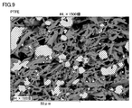
- Example 3 A composite web is produced in the same manner as in Example 2, except that the powder of PFA particles is changed to PTFE. Composite webs deposited under these conditions showed good dispersion of PTFE (see Figure 9).
- FIG. 9 is a cross-sectional photograph of the composite web of Example 3, and the hatched portion in FIG. 9 is PTFE.
- Example 4 Hydrophilic-treated PFA was added to the slurry of Example 1 so as to be 30% by volume, and a web was formed by deposition through a spray-drying process. Composite webs deposited under these conditions showed good dispersion of PFA (see Figure 10).
- FIG. 10 is a cross-sectional photograph of the composite web of Example 4, and the hatched portion in FIG. 10 is PFA.
- hydrophilic treatment surface treatment was performed using a powder plasma treatment device manufactured by Kai Semiconductor Co., Ltd. until PFA was mixed with the aqueous solution and dispersed.
- the powder plasma processing apparatus described above is a device for performing atmospheric pressure plasma processing in a liquid, and is a dielectric barrier discharge plasma device using water as a dielectric. Thus, a hydrophilically treated PFA dispersion was obtained.
- Example 5 A composite web is produced in the same manner as in Example 2, except that the powder of PFA particles is changed to polynorbornene. Composite webs deposited under these conditions showed good dispersion of polynorbornene.
- FIG. 11 shows a cross-sectional state of a film obtained by molding LCP and PFA by melt extrusion. Strong aggregation of PFA is seen.
- FIG. 5 is a photograph (scanning electron microscope image) of the cross section of the LCP web (surface parallel to the thickness direction of the web) in Example 1 (top) and Comparative Example 2 (bottom).
- the numerical value on the photograph of FIG. 5 shows the magnifying power of the microscope. From the photograph in FIG. 5, it can be seen that in Example 1, a web with high LCP fiber dispersion uniformity was produced. In addition, it can be seen that the LCP web of Example 1 is bulkier (has a higher porosity) than the LCP web produced by the papermaking method of Comparative Example 2.
Landscapes
- Engineering & Computer Science (AREA)
- Textile Engineering (AREA)
- Mechanical Engineering (AREA)
- Chemical & Material Sciences (AREA)
- Chemical Kinetics & Catalysis (AREA)
- Nonwoven Fabrics (AREA)
Abstract
本発明に基づく液晶ポリマーウェブの製造方法は、分散媒、および、前記分散媒中に分散された液晶ポリマー繊維を含むスラリーを調製する、スラリー調製工程と、前記スラリーを噴霧し、噴霧された前記スラリーを乾燥用気体によって乾燥する、噴霧乾燥工程と、噴霧乾燥された前記液晶ポリマー繊維を堆積させてウェブを形成する、堆積工程と、を備える。
Description
本発明は、液晶ポリマーウェブの製造方法に関する。
高周波FPC基板においては、主材料として液晶ポリマー(LCP)が使われているが、さらなる低誘電化が求められており、例えば、LCPにフッ素樹脂のような低誘電樹脂材を加えることが検討されている。その場合、フッ素樹脂の粉末を加えることが望ましい。また、フッ素樹脂以外にも、種々の機能を付与するための機能性フィラーをLCPに添加する要望は多い。
通常のLCPフィルムは溶融押出法で作成されるが、溶融押出法でフィラーをLCPに混ぜ込む場合、分散性、粘度の違い、分解による発ガスや腐食、延伸時のフィルム穴あき等の問題がある(特許文献3:特開2019-65061号公報)。
LCP繊維のウェブを作製し、それをプレスして充実化させることでフィルムにする方法も考えられる。ウェブの作製方法としては、LCPを繊維化し、スラリー化して湿式ウェブにする方法も提案されている。また、特許文献2(特開2003-129392号公報)のように、これにフィラーを混ぜることも提案されている。LCPを特許文献2よりも微細な繊維状にすれば、フィラーを混ぜ込んだLCPのウェブを熱プレスすることで、ウェブを薄いフィルム状に出来る可能性がある。
その他のウェブ作製の方法としては、カード法やエアレイ法に代表される乾式法が知られている。
カード法では、1~10cm程度の長さにカットされた繊維から、カードまたはエアランダム機を用いて、薄い連続ウェブが形成される。
エアレイド法では、まず、パルプシート、または、ショートカット若しくはチョップと呼ばれる長さ3~12mm程度の短繊維(合成繊維など)を、乾式で機械的に解繊する。解繊された短繊維を空気を媒介として走行する金網上に堆積させることで、連続ウェブを形成させる。
エアレイド法を応用した別の方法としては、例えば、特許文献1(特開2018-145574号公報)に開示されるウェブシートの製造方法が知られている。この方法では、繊維を回転駆動される円筒の篩によって選別し、選別された繊維を再度、回転駆動される円筒の篩によって分散させる。その分散された繊維の粉をダウンフローで吸引しながらメッシュベルト上に堆積させることで、ウェブシートが製造される。なお、特許文献1には、ウェブシートの作製に用いられる繊維の直径の平均が1μm以上1000μm以下であり、該繊維の長さが1μm以上5mm以下である旨記載されている。
LCPフィルムを作製する代表的な工法として、溶融押し出し法(横延伸)と溶融押し出し法(インフレーション)がある。この方法でフッ素樹脂と複合化を行う場合、棒状高分子であるLCPは、通常のランダムコイル型高分子と溶融粘度の温度依存性が違うため、溶融状態でLCPの粘度とフッ素樹脂の粘度が一致せず、フッ素樹脂との相溶性も低い。このため、フッ素樹脂が凝集体を作り、LCP中に均一に分散しにくい。
この課題の解決方法として抄紙法がある。抄紙法であれば溶融状態にはならないため、LCPの粘度とフッ素樹脂の溶融粘度の違いによるフッ素樹脂の凝集は生じない。しかし、フッ素樹脂は親水性が低いため、LCPの繊維状物を分散可能な水を含んだ分散媒中にフッ素樹脂を懸濁させることができない。
なお、水中に界面活性剤などの分散剤を添加すれば、疎水性の繊維等を水中に分散させることは可能であるが、界面活性剤は乾燥後もウェブ中に残存し、電子部品用のウェブの電気特性に悪影響を与える虞がある。
また、分散媒に有機溶媒を多く配合することで、疎水性の繊維をスラリー化することは可能である。しかし、抄紙法の場合は0.1%程度の希薄分散液を用いる必要があるため、大量の有機溶媒の使用が必要となり、安全性の問題や製造コストの増加が生じてしまう。
一方、乾式法であれば、フッ素樹脂の水への分散性は問題にならない。このため、例えば、エアレイ法等でLCP微細繊維とフッ素樹脂を混合することも考えられるが、LCP微細繊維は、乾燥させると凝集体を作りやすいため、篩いの通過や気中での分散が困難である。
また、カード法では、通常、20mm以下の短い繊維は用いることができない。エアレイド法では、20mm以下の短い繊維も用いることができるが、長さ(長手方向寸法)が数mm以下の繊維を用いることはできない。
特許文献1に記載の方法では、ミクロンオーダーの繊維でも用いることができる。さらに、カード法やエアレイド法と比較して、得られるウェブにおける繊維の分散均一性が高い。
しかしながら、特許文献1に記載の方法では、空気中での篩い機構で繊維を選別し分散させる。このため、破砕型液晶ポリマー繊維(LCP繊維)のような、帯電しやすく、微細な繊維を用いる場合、繊維の凝集性が高いため、繊維が篩いを抜けずに目詰まりが発生しやすいという問題がある。また、繊維の凝集物が発生し易いため、ウェブにおける繊維の分散均一性が低下してしまう。なお、繊維の分散均一性を改善するために、篩いの目開きのサイズを小さくすると、さらに目詰まりが発生し易くなってしまう。
さらに、特許文献1に記載の方法では、気流を制御して繊維をメッシュベルト上に堆積させる必要がある。しかし、その繊維サイズが小さくなるほど凝集しやすく、気流により均一に繊維を分散させるのが難しくなる。
また、ウェブの材料として複数種の材料を複合化して用いる場合、乾式法では空気中で異種粉末を分散させることになるが、攪拌力が湿式に比べて弱いため、液晶ポリマー繊維とは異なる粉体を均一に分散させることが難しい。
本発明は、上記の課題に鑑み、微細な液晶ポリマー繊維を用いて液晶ポリマーウェブを容易に製造することのできる製造方法を提供することを目的とする。
また、本発明の一態様においては、液晶ポリマー繊維と、液晶ポリマー繊維とは異なる固体材料と、を複合させてなるウェブを製造することのできる製造方法を提供することを目的とする。
本発明に基づく液晶ポリマーウェブの製造方法は、
分散媒、および、前記分散媒中に分散された液晶ポリマー繊維を含むスラリーを調製する、スラリー調製工程と、
前記スラリーを噴霧し、噴霧された前記スラリーを乾燥用気体によって乾燥する、噴霧乾燥工程と、
噴霧乾燥された前記液晶ポリマー繊維を堆積させてウェブを形成する、堆積工程と、を備える。
分散媒、および、前記分散媒中に分散された液晶ポリマー繊維を含むスラリーを調製する、スラリー調製工程と、
前記スラリーを噴霧し、噴霧された前記スラリーを乾燥用気体によって乾燥する、噴霧乾燥工程と、
噴霧乾燥された前記液晶ポリマー繊維を堆積させてウェブを形成する、堆積工程と、を備える。
本発明によれば、微細な液晶ポリマー繊維を用いて、液晶ポリマーウェブを容易に製造することができる。
また、本発明の一態様においては、液晶ポリマー繊維と、液晶ポリマー繊維とは異なる固体材料と、を複合させてなるウェブを製造することができる。
以下、本発明の一実施形態に係る液晶ポリマー(微細繊維)ウェブの製造方法について説明する。
<<液晶ポリマーウェブの製造方法>>
図1に示されるように、本実施形態に係る液晶ポリマーウェブの製造方法は、スラリー調製工程(S1)と、噴霧乾燥工程(S2)と、堆積工程(S3)と、を少なくとも備える。
図1に示されるように、本実施形態に係る液晶ポリマーウェブの製造方法は、スラリー調製工程(S1)と、噴霧乾燥工程(S2)と、堆積工程(S3)と、を少なくとも備える。
スラリー調製工程(S1)では、分散媒、および、分散媒中に分散された液晶ポリマー繊維を含むスラリーを調製する。
噴霧乾燥工程(S2)では、スラリーを噴霧し、噴霧されたスラリーを乾燥用気体によって乾燥する。
堆積工程(S3)では、噴霧乾燥された液晶ポリマー繊維を堆積させてウェブを形成する。
(液晶ポリマーウェブ)
本発明の一実施形態に係る液晶ポリマーウェブ(LCPウェブ)は、液晶ポリマー繊維(LCP繊維)を含むウェブである。
本発明の一実施形態に係る液晶ポリマーウェブ(LCPウェブ)は、液晶ポリマー繊維(LCP繊維)を含むウェブである。
LCPウェブは、液晶ポリマー繊維(LCP繊維)を主成分として含むことが好ましい。なお、本明細書において「主成分」とは、全成分に対する主成分の体積比率が最も多い成分であり、全成分に対する主成分の比率は、好ましくは50体積%以上90体積%以下であり、より好ましくは50体積%以上80体積%以下であり、さらに好ましくは50体積%以上70体積%以下である。LCPウェブは、LCP繊維のみから構成されていてもよく、LCP繊維と他の材料とを含んでいてもよい。
なお、LCPに複合させる複合材料(LCP繊維以外の材料)がLCPウェブの主成分であってもよい。その場合、LCPウェブの全成分に対する複合材料の比率は、好ましくは50体積%以上90体積%以下(LCP繊維が10体積%以上50体積%以下)、より好ましくは50体積%以上80体積%以下(LCP繊維が20体積%以上50体積%以下)、さらに好ましくは50体積%以上70体積%以下(LCP繊維が30体積%以上50体積%以下)である。
なお、本明細書において、「ウェブ」とは、LCP繊維が堆積してなるシート上のLCP繊維の集合体であり、LCP繊維同士は基本的には固着していないが、部分的に固着していてもよい。例えば、フラッシュランプを照射されたウェブも、ここで言う「ウェブ」に含まれる。
LCPウェブの厚さは、特に限定されないが、例えば5μm以上250μm以下である。
本実施形態に係るLCPウェブは、プレスすることによりフィルム化することができる。このフィルムは、少なくとも一方の面に銅箔が接合されていてもよく、両面に銅箔が接合されていてもよい。このように銅箔が接合されたLCPフィルムは、一つのラミネート状の成形体として、例えばサブトラクト法による回路形成が可能なFCCL(Flexible Copper Clad Laminates)として使用できる。
(液晶ポリマー繊維)
液晶ポリマー繊維(LCP繊維)は、液晶ポリマーを主成分として含む繊維状の粒子(材料)である。LCP繊維は、繊維状の部分を含んでいれば特に限定されない。繊維状の部分は直鎖状であってもよく、分岐等を有していてもよい。
液晶ポリマー繊維(LCP繊維)は、液晶ポリマーを主成分として含む繊維状の粒子(材料)である。LCP繊維は、繊維状の部分を含んでいれば特に限定されない。繊維状の部分は直鎖状であってもよく、分岐等を有していてもよい。
粉末状微細短繊維おけるLCP繊維(繊維状の粒子)の平均径は、より好ましくは2μm以下であり、より好ましくは1μm以下である。また、LCP繊維の平均アスペクト比は、好ましくは10以上500以下であり、より好ましくは300以下であり、さらに好ましくは100以下である。
なお、LCPパウダーに含まれるLCP繊維の平均径および平均アスペクト比は、以下の方法によって測定される。
(LCP繊維の平均径および平均アスペクト比の測定)
測定対象となるLCP繊維からなるLCPパウダーをエタノールに分散させて、0.01質量%のLCPパウダーが分散されたスラリーを調製する。このとき、スラリー中の水分の含有率が1質量%以下となるようにスラリーを調製する。そして、このスラリーをスライドガラス上に5~10μL滴下した後、スライドガラス上のスラリーを自然乾燥させる。スラリーを自然乾燥させることにより、スライドガラス上にLCPパウダーが配置される。
測定対象となるLCP繊維からなるLCPパウダーをエタノールに分散させて、0.01質量%のLCPパウダーが分散されたスラリーを調製する。このとき、スラリー中の水分の含有率が1質量%以下となるようにスラリーを調製する。そして、このスラリーをスライドガラス上に5~10μL滴下した後、スライドガラス上のスラリーを自然乾燥させる。スラリーを自然乾燥させることにより、スライドガラス上にLCPパウダーが配置される。
次に、スライドガラス上に配置されたLCPパウダーの所定の領域を、走査型電子顕微鏡で観察することにより、LCPパウダーを構成する粒子(LCP繊維)の画像データを100以上採集する。なお、画像データの採集においては、画像データの数が100以上となるように、LCPの一粒子あたりの大きさに応じて上記領域を設定する。また、LCPの各粒子について、画像データの採取の漏れまたは測定誤差の発生を抑制するため、走査型電子顕微鏡の拡大倍率を500倍、3000倍、または、10000倍に適宜変更して、上記画像データを採取する。
次に、採取した上記各画像データを用いて、LCP繊維の各々の長手方向寸法と、幅方向寸法とを測定する。
上記画像データの各々に撮影された一つのLCP繊維において、その一の端部から当該粒子の略中央を通って当該一の端部の反対側の端部に到達する経路のうち、最も長い経路の両端を結ぶ直線の方向を長手方向と定義する。そして、当該最も長い経路の両端を結ぶ直線の長さを、長手方向寸法として測定する。
また、LCPパウダーの一粒子の、上記長手方向において互いに異なる3箇所の地点で、長手方向に直交する方向における粒子の寸法を測定する。この3箇所の地点で測定された寸法の平均値を、LCPパウダーの一粒子あたりの幅方向寸法(繊維径)とする。
さらに、繊維径に対する長手方向寸法の比〔長手方向寸法/繊維径〕を算出して、LCP繊維のアスペクト比とする。
そして、100個のLCP繊維について測定された繊維径の平均値を平均径とする。
また、100個のLCP繊維について測定されたアスペクト比の平均値を平均アスペクト比とする。
また、100個のLCP繊維について測定されたアスペクト比の平均値を平均アスペクト比とする。
(液晶ポリマー:LCP)
液晶ポリマーとしては、特に限定されないが、例えば、サーモトロピック液晶ポリマーなどが挙げられる。
液晶ポリマーとしては、特に限定されないが、例えば、サーモトロピック液晶ポリマーなどが挙げられる。
液晶ポリマーはアミド結合を有していないことが好ましい。アミド結合を有していないサーモトロピック液晶ポリマーとしては、例えば、1型液晶ポリマーと呼ばれる融点が高く、CTEが低い、パラヒドロキシ安息香酸とテレフタル酸とジヒドロキシビフェニルとの共重合体(パラヒドロキシ安息香酸とエチレンテレフタレートとの共重合体)、または、1.5型(もしくは3型)と呼ばれる1型液晶ポリマーと2型液晶ポリマーとの間の融点を有するパラヒドロキシ安息香酸と2,6-ヒドロキシナフトエ酸との共重合体が挙げられる。
以下、本実施形態の製造方法の各工程について説明する。
<スラリー調製工程:S1>
スラリー調製工程(S1)は、分散媒、および、分散媒中に分散された液晶ポリマー繊維を含むスラリー(LCPスラリー)を調製する工程である。
<スラリー調製工程:S1>
スラリー調製工程(S1)は、分散媒、および、分散媒中に分散された液晶ポリマー繊維を含むスラリー(LCPスラリー)を調製する工程である。
スラリー調製工程においては、例えば、粉末状微細短繊維おけるLCP繊維(繊維状の粒子)を分散媒中に分散させることにより、LCPスラリーを調製することができる。
LCPスラリーの調製に用いられる分散媒としては、例えば、水、エタノール、メタノール、イソプロピルアルコール、トルエン、ベンゼン、キシレン、フェノール、アセトン、メチルエチルケトン、ジエチルエーテル、ジメチルエーテル、ヘキサン、N,N-ジメチルアセトアミド、テトラヒドロフラン、ジエチレングリコールモノヘキシルエーテル等、または、これらから選択される少なくとも2種の混合物等が挙げられる。これらの中でも好ましい分散媒は、水、エタノール、または、これらの混合物(エタノール水溶液)である。
なお、LCPスラリーの調製に用いられるLCPパウダーは、LCP繊維以外の粒子(実質的に繊維状の部分を含まない粒子、LCP繊維が凝集してなる塊状の粒子など)を含んでいてもよいが、その含有率(個数比率)は20%以下であることが好ましい。
また、LCPパウダーは、レーザ回折散乱法による粒子径分布測定装置を用いた粒度測定により測定されるD50(平均粒径)の値が、13μm以下であることが好ましい。
スラリー調製工程において、液晶ポリマー繊維と、液晶ポリマー繊維とは異なる固体材料と、をスラリー中に分散させてもよい。この場合、LCP繊維と固体材料とを含む複合体を形成させ、その複合体を堆積させることにより、LCP繊維と固体材料との分散均一性の高い液晶ポリマーウェブを得ることができる。なお、この場合に用いられる固体材料は、スラリーの分散媒に対して分散性が高い材料であることが好ましい。
<噴霧乾燥工程:S2>
噴霧乾燥工程は、スラリーを噴霧し、噴霧されたスラリーを乾燥用気体によって乾燥する工程である。
噴霧乾燥工程は、スラリーを噴霧し、噴霧されたスラリーを乾燥用気体によって乾燥する工程である。
噴霧乾燥工程(S2)において、スラリーを噴霧し、噴霧されたスラリーを乾燥用気体によって乾燥するための具体的な方法としては、例えば、図2に示されるように、循環する乾燥用気体2(熱風)の中(チャンバー3内)に噴霧装置1によりスラリーを噴霧して乾燥させる方法が挙げられる。
また、図3に示されるように、第1ノズル11および第2ノズル12によって、独立の2種の流体を噴出することのできる2流体ノズル有する噴霧装置13を備える噴霧乾燥装置を用いて、スラリーの噴霧乾燥を行ってもよい。例えば、第1ノズル11からLCPスラリーを噴霧し、第2ノズル12から乾燥用気体2(加温されたN2ガス等)を噴出することで、LCPスラリーが噴霧乾燥され、LCP繊維からなる微粉末が噴霧装置13の下方のチャンバー内に分散された状態となる。
噴霧乾燥工程において、液晶ポリマー繊維とは異なる固体材料(粉体、繊維状物など)を乾燥用気体中に分散させてもよい。この場合、LCP繊維と固体材料とを含む複合体を形成させ、その複合体を堆積させることにより、LCP繊維と固体材料との分散均一性の高い液晶ポリマーウェブを得ることができる。
ここで、乾燥用気体に配合される固体材料は、LCPスラリーの分散媒への分散性が低い材料(低分散性材料)を含むことが好ましい。
なお、LCPウェブにおいて、LCP繊維とそれ以外の固体材料を複合化させる場合において、該固体材料がLCPスラリーの分散媒に対して分散性が高い材料であるときは、LCPスラリー中に該固体材料を配合してもよく、乾燥用気体中に該固体材料を配合してもよい。固体材料がLCPスラリーの分散媒への分散性が低い材料であるときは、乾燥用気体中に当該固体材料を分散させることが好ましい。分散媒への分散性が低い固体材料をLCPスラリー中に配合する場合、材料の表面処理、分散媒への分散剤の添加などを行わない限り、LCPウェブにおいて該固体材料の分散均一性が低くなるためである。
例えば、分散性の1つの基準として、容量70mLのサンプル瓶(柏洋株式会社M-70)内のエタノール60質量%水溶液50mLの分散媒に、0.1体積%の固体材料を添加し、該サンプル瓶を10回手で振った後、卓上型超音波洗浄器「UT206」(シャープ株式会社製、発振周波数:37kHz)を用いて1分間超音波処理を行う。なお、0.1体積%は、湿式抄紙法で一般的に用いられるスラリー中の固形材料の濃度である。1分間の静置後、サンプル瓶内の気液面または底面に固体材料の存在が目視で確認できた場合、その固体材料は、当該分散媒への分散性が低い固体材料(低分散性材料)に該当する。
ここで、エタノール60質量%水溶液を評価分散媒としている理由は、エタノールの濃度が60wt%を超えるとエタノール水溶液が危険物扱いとなり、湿式抄紙法での取り扱いが格段に難しくなるためである。エタノール60wt%水溶液に分散出来ない材料は湿式抄紙法でのLCP繊維との複合化が難しいため、乾式法がより適していると考えられる。
低分散性材料としては、例えば、パーフルオロアルコキシアルカン(PFA)、ポリテトラフルオロエチレン(PTFE)、FEP(テフロン:登録商標)、シクロオレフィンポリマー(COP/COC)、ポリフェニレンエーテル(PPE)、シンジオタクチックポリスチレン(SPS)、ポリエーテルエーテルケトン(PEEK)、ビスマレイミド、ポリノルボルネン(PNB)、炭化水素系ポリマー材料などが挙げられる。ただし、この低分散性材料に該当する化合物の種類は、LCPスラリーの分散媒の種類によって変動し得る。
なお、一例として、平均粒径(D50)が2μmのパーフルオロアルコキシアルカン(PFA)、および、平均粒径が4μmのポリテトラフルオロエチレン(PTFE)は、分散媒としての60質量%のエタノールを含むエタノール水溶液)に対して上記の基準に基づく低分散性材料に該当することは、実験により確認されている。図6に、上記の低分散性の分散媒の確認試験(1分間の静置後)におけるPFA(図6(a))およびPTFE(図6(b))の分散液の写真を示す。
噴霧乾燥工程においては、乾燥用気体を再利用してもよい。乾燥用気体がN2等である場合に、乾燥用気体を再利用することで。環境面、コスト面などの負荷が低減される。
<堆積工程:S3>
堆積工程は、噴霧乾燥された液晶ポリマー繊維を堆積させてウェブを形成する工程である。
堆積工程は、噴霧乾燥された液晶ポリマー繊維を堆積させてウェブを形成する工程である。
例えば、図4に示されるように、噴霧乾燥工程によってチャンバー3内の気体中に分散状態になったLCP繊維の微粉末4をメッシュ6(コンベアメッシュ)の下方から吸引することで、メッシュ6上にLCP繊維の微粉末4を堆積させる。これによって堆積物5が得られる。
このように、凝集の少ない状態の噴霧乾燥後のLCP繊維を再度凝集させることなく、堆積させることで、LCP繊維の分散均一性の高いLCPウェブを得ることができる。
堆積物5からLCPウェブを作製する具体的な方法としては、例えば、LCP繊維の堆積物に対して、フラッシュランプ等による瞬間的な加熱処理を実施する方法が挙げられる。このような瞬間的な加熱処理により、LCP繊維同士を固着させることで、LCPウェブを作製することができる。なお、このように、堆積物に対して圧力を加えないような方法でLCP繊維同士を固着させた場合、嵩高い(空隙率が高い)LCPウェブを得ることができる。このような嵩高いLCPウェブは、従来の製造方法(特に、抄紙法などの湿式法)では得ることが難しい。
ただし、堆積物5からLCPウェブを作製する方法は特に限定されず、LCPウェブの用途に応じて、堆積物5に対して軽い加熱や加圧等でウェブの強度をメッシュから剥離できる程度に高めても良い。また、LCP繊維同士を接着剤等によって固着することで、LCPウェブを作製してもよい。
なお、得られたLCPウェブは、さらに、必要に応じて、プレス工程、巻き取り工程等の他の工程に付されてもよい。
以上で説明した本実施形態の製造方法によれば、微細な液晶ポリマー繊維を用いた場合であっても、液晶ポリマーウェブを容易に製造することができる。本実施形態の製造方法では、乾式法のように微細なLCP繊維が飛散することがなく、特許文献1に記載の方法のように微細なLCP繊維の目詰まりや気流の制御の問題が生じ難いためである。
また、LCP繊維のように、微細な繊維や帯電しやすい繊維は、凝集して凝集体を生じ易い。従来の乾式法において、気流中ではLCP繊維の凝集体を解繊してLCP繊維を十分に分散させることは困難である。これに対して、スラリー状態では、濡れ性の制御や攪拌を行うことによって、LCP繊維を十分に分散させることができる。そして、LCP繊維の分散状態が良好であるスラリーを噴霧乾燥することによって、気体中でLCP繊維の乾燥粉末を良好な分散状態で存在させ、その分散状態を維持したままの堆積物からLCPウェブを作製することができる。これにより、LCP繊維の大きさや帯電性にかかわらず、LCP繊維の分散均一性が高いLCPウェブを得ることができる。
また、本実施形態の製造方法においては、抄紙法よりも高濃度のLCP繊維のスラリーを噴霧乾燥させて気相中に分散させたLCP繊維を(捕集せずに)直接堆積させることにより、抄紙法に比べて溶剤の使用量を1/10程度に低減にすることができる。
<液晶ポリマーパウダーの作製方法>
以下、上述のスラリー調製工程に用いられる液晶ポリマーパウダーの一例について、作製方法の詳細を説明する。該液晶ポリマーパウダーは、例えば、以下の粗粉砕工程、微粉砕工程、粗粒除去工程、および、繊維化工程を、この順で実施することにより、作製することができる。
以下、上述のスラリー調製工程に用いられる液晶ポリマーパウダーの一例について、作製方法の詳細を説明する。該液晶ポリマーパウダーは、例えば、以下の粗粉砕工程、微粉砕工程、粗粒除去工程、および、繊維化工程を、この順で実施することにより、作製することができる。
液晶ポリマーパウダーの作製に用いられる液晶ポリマーからなる原料(LCP原料)の形状としては、例えば、二軸配向したフィルムまたはウェブ、一軸配向したペレット、粉体などが挙げられる。LCP原料を構成するLCPは、上述のLCP繊維を構成するLCPと同様である。
(粗粉砕工程)
粗粉砕工程においては、LCP原料を粗粉砕する。例えば、LCP原料を、カッターミルで粗粉砕する。粗粉砕されたLCP粒子の大きさは、後述する微粉砕工程の原料として用いることができる限り、特に限定されない。粗粉砕されたLCP粒子の最大粒径は、例えば3mm以下である。
粗粉砕工程においては、LCP原料を粗粉砕する。例えば、LCP原料を、カッターミルで粗粉砕する。粗粉砕されたLCP粒子の大きさは、後述する微粉砕工程の原料として用いることができる限り、特に限定されない。粗粉砕されたLCP粒子の最大粒径は、例えば3mm以下である。
なお、粗粉砕工程を必ずしも実施する必要はない。例えば、LCP原料が微粉砕工程の原料として用いることができるものであれば、LCP原料を直接微粉砕工程の原料として使用してもよい。
(微粉砕工程)
微粉砕工程においては、(粗粉砕工程後の)LCP原料を、液体窒素に分散させた状態で粉砕して、粒状の微粉砕液晶ポリマー(微粉砕LCP)を得る。
微粉砕工程においては、(粗粉砕工程後の)LCP原料を、液体窒素に分散させた状態で粉砕して、粒状の微粉砕液晶ポリマー(微粉砕LCP)を得る。
微粉砕工程においては、メディアを用いて、液体窒素に分散しているLCP原料を粉砕することが好ましい。メディアは、例えばビーズである。本実施形態の微粉砕工程においては、液体窒素を取り扱うという観点から、比較的技術的な問題が少ないビーズミルを用いることが好ましい。微粉砕工程に用いることができる装置としては、例えば、アイメックス社製の液体窒素ビーズミルである「LNM-08」が挙げられる。
微粉砕工程により得られる粒状の微粉砕LCPは、レーザ回折散乱法による粒子径分布測定装置で測定したD50が50μm以下であることが好ましい。これにより、下記に示す繊維化工程において粒状の微粉砕LCPがノズルで詰まることを抑制することができる。
(粗粒除去工程)
次に、粗粒除去工程において、上記微粉砕工程で得られた粒状の微粉砕LCPから粗粒を除去する。例えば、粒状の微粉砕LCPをメッシュで篩いにかけることにより、篩下の粒状の微粉砕LCPを得るとともに、篩上の粒状の液晶ポリマーを除去することで、粒状の微粉砕LCPに含まれる粗粒を除去することができる。メッシュの種類は適宜選択すればよいが、メッシュとしては、例えば目開きが53μmのものが挙げられる。なお、粗粒除去工程を必ずしも実施する必要はない。
次に、粗粒除去工程において、上記微粉砕工程で得られた粒状の微粉砕LCPから粗粒を除去する。例えば、粒状の微粉砕LCPをメッシュで篩いにかけることにより、篩下の粒状の微粉砕LCPを得るとともに、篩上の粒状の液晶ポリマーを除去することで、粒状の微粉砕LCPに含まれる粗粒を除去することができる。メッシュの種類は適宜選択すればよいが、メッシュとしては、例えば目開きが53μmのものが挙げられる。なお、粗粒除去工程を必ずしも実施する必要はない。
(繊維化工程)
次に、繊維化工程において、粒状液晶ポリマーを湿式高圧破砕装置で破砕して、液晶ポリマーパウダーを得る。繊維化工程においては、まず、微粉砕LCPを繊維化工程用の分散媒に分散させる。分散させる微粉砕LCPは、粗粒が除去されていなくてもよいが、粗粒が除去されていることが好ましい。繊維化工程用の分散媒としては、例えば、水、エタノール、メタノール、イソプロピルアルコール、トルエン、ベンゼン、キシレン、フェノール、アセトン、メチルエチルケトン、ジエチルエーテル、ジメチルエーテル、ヘキサン、または、これらの混合物等が挙げられる。この繊維化工程で用いる分散媒は、上述のLCPスラリーの分散媒と同じであることが好ましい。
次に、繊維化工程において、粒状液晶ポリマーを湿式高圧破砕装置で破砕して、液晶ポリマーパウダーを得る。繊維化工程においては、まず、微粉砕LCPを繊維化工程用の分散媒に分散させる。分散させる微粉砕LCPは、粗粒が除去されていなくてもよいが、粗粒が除去されていることが好ましい。繊維化工程用の分散媒としては、例えば、水、エタノール、メタノール、イソプロピルアルコール、トルエン、ベンゼン、キシレン、フェノール、アセトン、メチルエチルケトン、ジエチルエーテル、ジメチルエーテル、ヘキサン、または、これらの混合物等が挙げられる。この繊維化工程で用いる分散媒は、上述のLCPスラリーの分散媒と同じであることが好ましい。
そして、繊維化工程用の分散媒に分散させた状態の微粉砕LCP、すなわち、ペースト状またはスラリー状の微粉砕LCPを、高圧で加圧した状態で、ノズルを通過させる。高圧でノズルを通過させることにより、ノズルでの高速流動による剪断力または衝突エネルギーが液晶ポリマーに作用して、粒状の微粉砕LCPを破砕することで、液晶ポリマーの繊維化が進行し、微細なLCP繊維からなる液晶ポリマーパウダーを得ることができる。上記ノズルのノズル径は、高い剪断力または高い衝突エネルギーを与えるという観点から、上記ノズルにおいて微粉砕LCPの詰まりが発生しない範囲で可能な限り小さくすることが好ましい。上記の粒状の微粉砕LCPは粒径が比較的小さいため、繊維化工程において用いる湿式高圧破砕装置におけるノズル径を小さくすることができる。ノズル径は、例えば0.2mm以下である。
なお、上述したように、粒状の微粉砕LCPに複数の微細なクラックが形成されている。このため、湿式高圧破砕装置での加圧により、分散媒が、微細なクラックから微粉砕LCPの内部に侵入する。そして、ペースト状またはスラリー状の微粉砕LCPがノズルを通過して常圧下に位置したときに、微粉砕LCPの内部に侵入した分散媒がわずかな時間で膨張する。微粉砕LCP内部に侵入した分散媒が膨張することにより、微粉砕LCPの内部から、破壊が進行する。このため、微粉砕LCPの内部まで繊維化が進み、かつ、液晶ポリマーの分子が一方向に並んでいるドメイン単位に分離する。このように、本実施形態における繊維化工程においては、本実施形態における微粉砕工程で得られた粒状の微粉砕LCPを解繊することで、従来の凍結粉砕法で得られた粒状の液晶ポリマーを破砕することで得られる液晶ポリマーパウダーより、塊状粒子の含有率が低く、かつ、微細なLCP繊維からなる、液晶ポリマーパウダーを得ることができる。
なお、本実施形態における繊維化工程においては、微粉砕LCPを、複数回、湿式高圧破砕装置で破砕することにより、液晶ポリマーパウダーを得てもよい。ただし、製造効率の観点からは、湿式高圧破砕装置による破砕の回数は少ないことが好ましく、例えば、5回以下である。
以下、実施例を挙げて本発明をより詳細に説明するが、本発明はこれらに限定されるものではない。
<実施例1>
(スラリー調製工程:S1)
まず、LCP原料として、分子が面方向に2軸配向したLCPフィルム(融点:315℃、厚み:250μm)を用意した。LCPの材質は、パラヒドロキシ安息香酸と4,6-ヒドロキシナフトエ酸との共重合体である。
(スラリー調製工程:S1)
まず、LCP原料として、分子が面方向に2軸配向したLCPフィルム(融点:315℃、厚み:250μm)を用意した。LCPの材質は、パラヒドロキシ安息香酸と4,6-ヒドロキシナフトエ酸との共重合体である。
このLCP原料をカッターミル(IKA製、MF10)により粗粉砕した。粗粉砕されたLCPを、カッターミルの排出口に設けられた目開き3mmのメッシュを通過させることで、粗粉砕LCPを得た。
次に、粗粉砕LCPを、液体窒素ビーズミル(アイメックス社製、LNM-08、ベッセル容量:0.8L)で微粉砕した。具体的には、500mLのメディアと、30gの粗粉砕LCPとをベッセルに投入して、回転数2000rpmで120分間粉砕処理を行った。メディアとしては、直径が5mmのジルコニア(ZrO2)製のビーズを使用した。なお、液体窒素ビーズミルにおいては、粗粉砕LCPが液体窒素中に分散した状態で、湿式粉砕処理が行われる。このように、粗粉砕LCPを、液体窒素ビーズミルで粉砕することにより、粒状の微粉砕LCPが得られた。
この微粉砕LCPについて、粒度分布を測定した。粒度測定においては、分散媒に分散させた微粉砕LCPについて、10秒間の超音波処理を実施した後、レーザ回折散乱法による粒子径分布測定装置(堀場製作所製、LA-950)にセットして、粒度分布の測定を行った。なお、分散媒としては、エタノールを主剤とした混合溶剤であるエキネン(登録商標、日本アルコール販売株式会社)を用いた。微粉砕LCPのD50の測定値は23μmであった。
次に、微粉砕LCPをエキネンに分散させてなる分散液を、目開き53μmのメッシュで篩い、微粉砕LCPに含まれる粗粒を除去するとともに、メッシュを通過した微粉砕LCPを回収した。当該粗粒除去による微粉砕LCPの収率は85質量%であった。
次に、粗粒が除去された微粉砕LCPを、20質量%エタノール水溶液に分散させた。微粉砕LCPが分散したエタノールスラリーを、湿式高圧破砕装置を用いて、ノズル径0.18mm、圧力200MPaの条件にて、繰り返し5回破砕することにより、繊維化した。湿式高圧破砕装置としては、高圧分散機(スギノマシン製のスターバーストラボ)を用いた。これにより、LCPパウダー(LCP繊維)がエタノール水溶液に分散されたスラリーが調製された。このスラリーをさらに、エタノール水溶液(エタノール濃度:50質量%)を用いて、LCPの濃度が1質量%になるように希釈した。これにより、次の噴霧乾燥工程で用いられるLCPスラリーが調製された。
(噴霧乾燥工程:S2)
上記のようにして調製されたLCPスラリーを噴霧乾燥した。具体的には、図3に示されるような、第1ノズル11および第2ノズル12によって、独立の2種の流体を噴出することのできる2流体ノズル有する噴霧装置13を備える噴霧乾燥装置を用いて、噴霧乾燥を行った。すなわち、第1ノズル11からLCPスラリーを噴霧し、第2ノズル12から乾燥用気体として180℃に加温されたN2ガスが噴出されることで、LCPスラリーが噴霧乾燥され、LCP繊維からなる微粉末が噴霧装置13の下方のチャンバー内に分散された状態となった。
上記のようにして調製されたLCPスラリーを噴霧乾燥した。具体的には、図3に示されるような、第1ノズル11および第2ノズル12によって、独立の2種の流体を噴出することのできる2流体ノズル有する噴霧装置13を備える噴霧乾燥装置を用いて、噴霧乾燥を行った。すなわち、第1ノズル11からLCPスラリーを噴霧し、第2ノズル12から乾燥用気体として180℃に加温されたN2ガスが噴出されることで、LCPスラリーが噴霧乾燥され、LCP繊維からなる微粉末が噴霧装置13の下方のチャンバー内に分散された状態となった。
(堆積工程:S3)
噴霧装置13の下方に40cm離れた位置に目開き11μmのメッシュ(株式会社くればぁ製)を設置し、メッシュの下方から吸引することで、チャンバー内に分散されたLCP繊維からなる微粉末を該メッシュ上に堆積させ、所定量のLCP繊維を堆積させた後、該メッシュを取り出した(図4参照)。
噴霧装置13の下方に40cm離れた位置に目開き11μmのメッシュ(株式会社くればぁ製)を設置し、メッシュの下方から吸引することで、チャンバー内に分散されたLCP繊維からなる微粉末を該メッシュ上に堆積させ、所定量のLCP繊維を堆積させた後、該メッシュを取り出した(図4参照)。
取り出したメッシュ上のLCP繊維の堆積物に対して、フラッシュランプで加熱処理を行い、メッシュから剥がせる程度の強度を得るために表面部分のLCP繊維同士を固着することで、LCPウェブを作製した。得られたLCPウェブをメッシュから剥がすことにより、実施例1のLCPウェブを得た。なお、得られたLCPウェブの厚さはおよそ100μmであった(図5)。
<実施例2>
実施例1と同様のスラリーを、同様の条件で噴霧する。このとき、噴霧乾燥工程において、平均粒径(D50)が2μmのPFA粒子の粉末を30体積%濃度になるように乾燥用気体中に分散させる。それ以外は、実施例1と同様にしてLCPウェブを作製する。得られた複合ウェブは、PFAの良好な分散性を示す(図7参照)。なお、図7は実施例2の複合ウェブの断面写真であり、図7において斜線のハッチングで示す部分がPFAである。このウェブを充実化させた(プレス後の)フィルムも、後述の比較例1(図11)に比べて、PFAの良好な分散性を示す(図8参照)。図8は上記フィルムの断面写真である。
実施例1と同様のスラリーを、同様の条件で噴霧する。このとき、噴霧乾燥工程において、平均粒径(D50)が2μmのPFA粒子の粉末を30体積%濃度になるように乾燥用気体中に分散させる。それ以外は、実施例1と同様にしてLCPウェブを作製する。得られた複合ウェブは、PFAの良好な分散性を示す(図7参照)。なお、図7は実施例2の複合ウェブの断面写真であり、図7において斜線のハッチングで示す部分がPFAである。このウェブを充実化させた(プレス後の)フィルムも、後述の比較例1(図11)に比べて、PFAの良好な分散性を示す(図8参照)。図8は上記フィルムの断面写真である。
<実施例3>
PFA粒子の粉末をPTFEに変更する点以外は、実施例2と同様にして複合ウェブを作製する。この条件で堆積させた複合ウェブは、PTFEの良好な分散性を示した(図9参照)。なお、図9は実施例3の複合ウェブの断面写真であり、図9において斜線のハッチングで示す部分がPTFEである。
PFA粒子の粉末をPTFEに変更する点以外は、実施例2と同様にして複合ウェブを作製する。この条件で堆積させた複合ウェブは、PTFEの良好な分散性を示した(図9参照)。なお、図9は実施例3の複合ウェブの断面写真であり、図9において斜線のハッチングで示す部分がPTFEである。
<実施例4>
実施例1のスラリーに親水処理を行ったPFAを30体積%になるように加えて噴霧乾燥工程を経て堆積させることでウェブ化した。この条件で堆積させた複合ウェブはPFAの良好な分散性を示した(図10参照)。なお、図10は実施例4の複合ウェブの断面写真であり、図10において斜線のハッチングで示す部分がPFAである。
実施例1のスラリーに親水処理を行ったPFAを30体積%になるように加えて噴霧乾燥工程を経て堆積させることでウェブ化した。この条件で堆積させた複合ウェブはPFAの良好な分散性を示した(図10参照)。なお、図10は実施例4の複合ウェブの断面写真であり、図10において斜線のハッチングで示す部分がPFAである。
親水処理としては、株式会社魁半導体製の粉体プラズマ処置装置によって、PFAが水系溶液と混和して分散するまで表面処理を行なった。なお、上記粉体プラズマ処理装置は、液体中で大気圧プラズマ処理を行なう装置であり、水を誘電体として用いた誘電体バリア放電プラズマ装置である。こうして親水処理済みのPFAの分散液を得た。
<実施例5>
PFA粒子の粉末をポリノルボルネンに変更する点以外は、実施例2と同様にして複合ウェブを作製する。この条件で堆積させた複合ウェブは、ポリノルボルネンの良好な分散性を示した。
PFA粒子の粉末をポリノルボルネンに変更する点以外は、実施例2と同様にして複合ウェブを作製する。この条件で堆積させた複合ウェブは、ポリノルボルネンの良好な分散性を示した。
<比較例1>
LCPとPFAを溶融押し出し法で成形したフィルムの断面状態を図11に示す。PFAの激しい凝集が見られる。
LCPとPFAを溶融押し出し法で成形したフィルムの断面状態を図11に示す。PFAの激しい凝集が見られる。
<比較例2>
実施例1のスラリー調製工程と同様にして作製されたLCPスラリーをエタノール水溶液(エタノール濃度:50質量%)を用いて、LCPの濃度が0.1質量%になるように希釈した。この希釈後のLCPスラリーを用いて、角型抄紙法(湿式法)により、比較例2のLCPウェブを作製した。
実施例1のスラリー調製工程と同様にして作製されたLCPスラリーをエタノール水溶液(エタノール濃度:50質量%)を用いて、LCPの濃度が0.1質量%になるように希釈した。この希釈後のLCPスラリーを用いて、角型抄紙法(湿式法)により、比較例2のLCPウェブを作製した。
<比較例3>
実施例1のスラリー調製工程と同様にして噴霧して生成されたLCP繊維を回収し、目開き150μmのふるい(サンポー製)でふるいがけを行い堆積させることでウェブ化することを試みた。しかし、LCP繊維が凝集しており篩いを通すことが出来ず、LCPウェブを作製することが出来なかった。
実施例1のスラリー調製工程と同様にして噴霧して生成されたLCP繊維を回収し、目開き150μmのふるい(サンポー製)でふるいがけを行い堆積させることでウェブ化することを試みた。しかし、LCP繊維が凝集しており篩いを通すことが出来ず、LCPウェブを作製することが出来なかった。
[LCPウェブの観察]
実施例1および比較例2で得られたLCPウェブ(ウェブ)に樹脂を充填した後に樹脂を固化することで、観察用サンプルを作製し、そのサンプルを研磨することにより断面(厚み方向に平行な面)を作製する。その研磨断面をさらにCP(化学研磨)で加工した後に、該研磨断面を走査型顕微鏡で観察した。
実施例1および比較例2で得られたLCPウェブ(ウェブ)に樹脂を充填した後に樹脂を固化することで、観察用サンプルを作製し、そのサンプルを研磨することにより断面(厚み方向に平行な面)を作製する。その研磨断面をさらにCP(化学研磨)で加工した後に、該研磨断面を走査型顕微鏡で観察した。
図5は、実施例1(上側)および比較例2(下側)におけるLCPウェブの断面(ウェブの厚み方向に平行な面)を撮影した写真(走査型電子顕微鏡像)である。なお、図5の写真の上の数値は顕微鏡の拡大倍率を示す。図5の写真から、実施例1では、LCP繊維の分散均一性が高いウェブが製造できていることが分かる。また、実施例1のLCPウェブは、比較例2の抄紙法で作製されたLCPウェブに比べて、嵩高い(空隙率が大きい)ことが分かる。
上述した実施形態の説明において、組み合わせ可能な構成を相互に組み合わせてもよい。
今回開示された実施形態および実施例はすべての点で例示であって制限的なものではないと考えられるべきである。本発明の範囲は上記した説明ではなくて請求の範囲によって示され、請求の範囲と均等の意味および範囲内でのすべての変更が含まれることが意図される。
1,13 噴霧装置、11 第1ノズル、12 第2ノズル、2 乾燥用気体、3 チャンバー、4 LCP繊維の微粉末、5 堆積物、6 メッシュ。
Claims (5)
- 分散媒、および、前記分散媒中に分散された液晶ポリマー繊維を含むスラリーを調製する、スラリー調製工程と、
前記スラリーを噴霧し、噴霧された前記スラリーを乾燥用気体によって乾燥する、噴霧乾燥工程と、
噴霧乾燥された前記液晶ポリマー繊維を堆積させてウェブを形成する、堆積工程と、
を備える、液晶ポリマーウェブの製造方法。 - 前記噴霧乾燥工程において、前記液晶ポリマー繊維とは異なる固体材料を前記乾燥用気体中に分散させる、請求項1に記載の製造方法。
- 前記固体材料は、前記スラリー中の前記分散媒への分散性が低い材料を含む、請求項2に記載の製造方法。
- 前記スラリー調製工程において、前記液晶ポリマー繊維と前記液晶ポリマー繊維とは異なる固体材料とを前記スラリー中に分散させる、請求項1に記載の製造方法。
- 前記噴霧乾燥工程において、前記乾燥用気体を再利用する、請求項1~4のいずれか1項に記載の製造方法。
Priority Applications (2)
| Application Number | Priority Date | Filing Date | Title |
|---|---|---|---|
| JP2023527548A JPWO2022259753A1 (ja) | 2021-06-07 | 2022-04-07 | |
| CN202280016678.1A CN116917562A (zh) | 2021-06-07 | 2022-04-07 | 液晶聚合物网的制造方法 |
Applications Claiming Priority (2)
| Application Number | Priority Date | Filing Date | Title |
|---|---|---|---|
| JP2021095206 | 2021-06-07 | ||
| JP2021-095206 | 2021-06-07 |
Publications (1)
| Publication Number | Publication Date |
|---|---|
| WO2022259753A1 true WO2022259753A1 (ja) | 2022-12-15 |
Family
ID=84425866
Family Applications (1)
| Application Number | Title | Priority Date | Filing Date |
|---|---|---|---|
| PCT/JP2022/017257 WO2022259753A1 (ja) | 2021-06-07 | 2022-04-07 | 液晶ポリマーウェブの製造方法 |
Country Status (3)
| Country | Link |
|---|---|
| JP (1) | JPWO2022259753A1 (ja) |
| CN (1) | CN116917562A (ja) |
| WO (1) | WO2022259753A1 (ja) |
Citations (4)
| Publication number | Priority date | Publication date | Assignee | Title |
|---|---|---|---|---|
| JPH02234909A (ja) * | 1989-02-01 | 1990-09-18 | E I Du Pont De Nemours & Co | リオトロピック液晶ポリマーからサブデニール繊維を製造する方法 |
| WO2008102538A1 (ja) * | 2007-02-21 | 2008-08-28 | Panasonic Corporation | ナノファイバ製造装置 |
| CN102071542A (zh) * | 2011-02-22 | 2011-05-25 | 天津工业大学 | 一种聚合物纳微纤维非织造布的制备方法 |
| WO2021060255A1 (ja) * | 2019-09-25 | 2021-04-01 | 株式会社村田製作所 | 液晶ポリマーパウダーおよびその製造方法 |
-
2022
- 2022-04-07 WO PCT/JP2022/017257 patent/WO2022259753A1/ja active Application Filing
- 2022-04-07 CN CN202280016678.1A patent/CN116917562A/zh active Pending
- 2022-04-07 JP JP2023527548A patent/JPWO2022259753A1/ja active Pending
Patent Citations (4)
| Publication number | Priority date | Publication date | Assignee | Title |
|---|---|---|---|---|
| JPH02234909A (ja) * | 1989-02-01 | 1990-09-18 | E I Du Pont De Nemours & Co | リオトロピック液晶ポリマーからサブデニール繊維を製造する方法 |
| WO2008102538A1 (ja) * | 2007-02-21 | 2008-08-28 | Panasonic Corporation | ナノファイバ製造装置 |
| CN102071542A (zh) * | 2011-02-22 | 2011-05-25 | 天津工业大学 | 一种聚合物纳微纤维非织造布的制备方法 |
| WO2021060255A1 (ja) * | 2019-09-25 | 2021-04-01 | 株式会社村田製作所 | 液晶ポリマーパウダーおよびその製造方法 |
Also Published As
| Publication number | Publication date |
|---|---|
| CN116917562A (zh) | 2023-10-20 |
| JPWO2022259753A1 (ja) | 2022-12-15 |
Similar Documents
| Publication | Publication Date | Title |
|---|---|---|
| CN105401333B (zh) | 薄片制造装置、薄片制造方法和通过它们制造的薄片、以及用于它们的复合体及其收纳容器 | |
| JP7405146B2 (ja) | 液晶ポリマーパウダーおよびその製造方法 | |
| JP7260054B2 (ja) | 液晶ポリマーフィルムおよびその製造方法 | |
| JP4841987B2 (ja) | フレーク銀粉及びその製造方法 | |
| JP7127746B2 (ja) | 樹脂シート及び樹脂多層基板 | |
| TW202010767A (zh) | 片材製造用結合素材、收容容器、片材及片材製造裝置 | |
| EP3913017A2 (en) | Starch composite for binding fibers, fiber structure, and fiber structure-manufacturing apparatus | |
| JP7234525B2 (ja) | シート製造用結合素材、収容容器、シート製造装置、シート製造方法及び粉体セット | |
| WO2022259753A1 (ja) | 液晶ポリマーウェブの製造方法 | |
| US20230416987A1 (en) | Method for producing fiber mat and fiber mat | |
| JP3467778B2 (ja) | フッ素系重合体粉末およびその製造方法 | |
| CN111566048B (zh) | 非晶质二氧化硅粉末及其制造方法、用途 | |
| Palaniandy et al. | Value adding limestone to filler grade through an ultra-fine grinding process in jet mill for use in plastic industries | |
| WO2024029207A1 (ja) | 液晶ポリマーフィルムおよびこれを備えた積層体、ならびに、液晶ポリマーフィルムの製造方法 | |
| WO2023228904A1 (ja) | 液晶ポリマーペレット、液晶ポリマーパウダー、液晶ポリマーフィルム、および、それらの製造方法 | |
| WO2023228903A1 (ja) | 液晶ポリマーパウダー、液晶ポリマーフィルム、および、それらの製造方法 | |
| WO2023074737A1 (ja) | 多孔体および多孔体の製造方法 | |
| US20240150655A1 (en) | Method for manufacturing fiber mat, and fiber mat | |
| WO2023033052A1 (ja) | 液晶ポリマーフィルムおよび液晶ポリマーフィルムの製造方法 | |
| JP2003025325A (ja) | 複合粒子の製造方法 | |
| KR20220158736A (ko) | 복합 입자, 복합 입자의 제조 방법, 액상 조성물, 적층체의 제조 방법 및 필름의 제조 방법 | |
| CN118043185A (zh) | 成型体和成型体的制造方法 | |
| JP2023164471A (ja) | 銀粉及び導電性ペースト | |
| JP2023165405A (ja) | 銀粉の製造方法 | |
| JP2003276024A (ja) | プリプレグと積層板の製造方法、及びプリプレグの製造装置 |
Legal Events
| Date | Code | Title | Description |
|---|---|---|---|
| 121 | Ep: the epo has been informed by wipo that ep was designated in this application |
Ref document number: 22819941 Country of ref document: EP Kind code of ref document: A1 |
|
| ENP | Entry into the national phase |
Ref document number: 2023527548 Country of ref document: JP Kind code of ref document: A |
|
| WWE | Wipo information: entry into national phase |
Ref document number: 202280016678.1 Country of ref document: CN |
|
| NENP | Non-entry into the national phase |
Ref country code: DE |