WO2023228904A1 - 液晶ポリマーペレット、液晶ポリマーパウダー、液晶ポリマーフィルム、および、それらの製造方法 - Google Patents
液晶ポリマーペレット、液晶ポリマーパウダー、液晶ポリマーフィルム、および、それらの製造方法 Download PDFInfo
- Publication number
- WO2023228904A1 WO2023228904A1 PCT/JP2023/018960 JP2023018960W WO2023228904A1 WO 2023228904 A1 WO2023228904 A1 WO 2023228904A1 JP 2023018960 W JP2023018960 W JP 2023018960W WO 2023228904 A1 WO2023228904 A1 WO 2023228904A1
- Authority
- WO
- WIPO (PCT)
- Prior art keywords
- liquid crystal
- crystal polymer
- lcp
- fiber mat
- powder
- Prior art date
Links
- 229920000106 Liquid crystal polymer Polymers 0.000 title claims abstract description 653
- 239000004977 Liquid-crystal polymers (LCPs) Substances 0.000 title claims abstract description 650
- 239000008188 pellet Substances 0.000 title claims abstract description 123
- 239000000843 powder Substances 0.000 title claims description 171
- 238000004519 manufacturing process Methods 0.000 title claims description 65
- 239000000463 material Substances 0.000 claims abstract description 35
- 238000004736 wide-angle X-ray diffraction Methods 0.000 claims abstract description 12
- 239000000835 fiber Substances 0.000 claims description 144
- 238000000034 method Methods 0.000 claims description 108
- 239000002994 raw material Substances 0.000 claims description 52
- RYGMFSIKBFXOCR-UHFFFAOYSA-N Copper Chemical compound [Cu] RYGMFSIKBFXOCR-UHFFFAOYSA-N 0.000 claims description 48
- 239000011889 copper foil Substances 0.000 claims description 47
- IJGRMHOSHXDMSA-UHFFFAOYSA-N Atomic nitrogen Chemical compound N#N IJGRMHOSHXDMSA-UHFFFAOYSA-N 0.000 claims description 46
- 238000001125 extrusion Methods 0.000 claims description 41
- 238000010298 pulverizing process Methods 0.000 claims description 41
- 238000002844 melting Methods 0.000 claims description 34
- 230000008018 melting Effects 0.000 claims description 34
- 238000010438 heat treatment Methods 0.000 claims description 31
- 239000002612 dispersion medium Substances 0.000 claims description 28
- 238000007731 hot pressing Methods 0.000 claims description 26
- 239000007788 liquid Substances 0.000 claims description 23
- 229910052757 nitrogen Inorganic materials 0.000 claims description 23
- XLYOFNOQVPJJNP-UHFFFAOYSA-N water Substances O XLYOFNOQVPJJNP-UHFFFAOYSA-N 0.000 claims description 23
- 239000002002 slurry Substances 0.000 claims description 21
- 238000001816 cooling Methods 0.000 claims description 19
- 238000001035 drying Methods 0.000 claims description 18
- 239000006185 dispersion Substances 0.000 claims description 16
- 239000000155 melt Substances 0.000 claims description 16
- 150000003755 zirconium compounds Chemical class 0.000 claims description 16
- 238000004898 kneading Methods 0.000 claims description 15
- 238000005520 cutting process Methods 0.000 claims description 12
- 238000003825 pressing Methods 0.000 claims description 11
- 238000000576 coating method Methods 0.000 claims description 8
- 239000011248 coating agent Substances 0.000 claims description 5
- 238000000465 moulding Methods 0.000 claims description 2
- 229920006254 polymer film Polymers 0.000 claims description 2
- 239000002245 particle Substances 0.000 description 78
- 230000008569 process Effects 0.000 description 41
- MCMNRKCIXSYSNV-UHFFFAOYSA-N ZrO2 Inorganic materials O=[Zr]=O MCMNRKCIXSYSNV-UHFFFAOYSA-N 0.000 description 35
- LFQSCWFLJHTTHZ-UHFFFAOYSA-N Ethanol Chemical compound CCO LFQSCWFLJHTTHZ-UHFFFAOYSA-N 0.000 description 27
- 230000000052 comparative effect Effects 0.000 description 25
- 238000005259 measurement Methods 0.000 description 23
- FJKROLUGYXJWQN-UHFFFAOYSA-N 4-hydroxybenzoic acid Chemical compound OC(=O)C1=CC=C(O)C=C1 FJKROLUGYXJWQN-UHFFFAOYSA-N 0.000 description 18
- 239000011362 coarse particle Substances 0.000 description 11
- 238000000227 grinding Methods 0.000 description 11
- 239000011148 porous material Substances 0.000 description 10
- 229940090248 4-hydroxybenzoic acid Drugs 0.000 description 9
- 239000011888 foil Substances 0.000 description 9
- 229910052751 metal Inorganic materials 0.000 description 9
- 239000002184 metal Substances 0.000 description 9
- 239000000243 solution Substances 0.000 description 9
- 238000012545 processing Methods 0.000 description 8
- 238000003860 storage Methods 0.000 description 8
- WUOACPNHFRMFPN-UHFFFAOYSA-N alpha-terpineol Chemical compound CC1=CCC(C(C)(C)O)CC1 WUOACPNHFRMFPN-UHFFFAOYSA-N 0.000 description 7
- 239000011324 bead Substances 0.000 description 7
- 230000007423 decrease Effects 0.000 description 7
- SQIFACVGCPWBQZ-UHFFFAOYSA-N delta-terpineol Natural products CC(C)(O)C1CCC(=C)CC1 SQIFACVGCPWBQZ-UHFFFAOYSA-N 0.000 description 7
- 238000010586 diagram Methods 0.000 description 7
- 229940116411 terpineol Drugs 0.000 description 7
- NIOAVQYSSKOCQP-UHFFFAOYSA-N 4-hydroxynaphthalene-2-carboxylic acid Chemical compound C1=CC=CC2=CC(C(=O)O)=CC(O)=C21 NIOAVQYSSKOCQP-UHFFFAOYSA-N 0.000 description 6
- 238000010521 absorption reaction Methods 0.000 description 6
- 239000007864 aqueous solution Substances 0.000 description 6
- 238000004458 analytical method Methods 0.000 description 5
- 229920001577 copolymer Polymers 0.000 description 5
- 229920001721 polyimide Polymers 0.000 description 5
- 238000010079 rubber tapping Methods 0.000 description 5
- 238000004804 winding Methods 0.000 description 5
- 238000005266 casting Methods 0.000 description 4
- 238000001514 detection method Methods 0.000 description 4
- 239000011521 glass Substances 0.000 description 4
- 230000001678 irradiating effect Effects 0.000 description 4
- 239000000758 substrate Substances 0.000 description 4
- 238000012360 testing method Methods 0.000 description 4
- ZWEHNKRNPOVVGH-UHFFFAOYSA-N 2-Butanone Chemical compound CCC(C)=O ZWEHNKRNPOVVGH-UHFFFAOYSA-N 0.000 description 3
- CSCPPACGZOOCGX-UHFFFAOYSA-N Acetone Chemical compound CC(C)=O CSCPPACGZOOCGX-UHFFFAOYSA-N 0.000 description 3
- UHOVQNZJYSORNB-UHFFFAOYSA-N Benzene Chemical compound C1=CC=CC=C1 UHOVQNZJYSORNB-UHFFFAOYSA-N 0.000 description 3
- RTZKZFJDLAIYFH-UHFFFAOYSA-N Diethyl ether Chemical compound CCOCC RTZKZFJDLAIYFH-UHFFFAOYSA-N 0.000 description 3
- KFZMGEQAYNKOFK-UHFFFAOYSA-N Isopropanol Chemical compound CC(C)O KFZMGEQAYNKOFK-UHFFFAOYSA-N 0.000 description 3
- OKKJLVBELUTLKV-UHFFFAOYSA-N Methanol Chemical compound OC OKKJLVBELUTLKV-UHFFFAOYSA-N 0.000 description 3
- 229920001410 Microfiber Polymers 0.000 description 3
- YXFVVABEGXRONW-UHFFFAOYSA-N Toluene Chemical compound CC1=CC=CC=C1 YXFVVABEGXRONW-UHFFFAOYSA-N 0.000 description 3
- QCWXUUIWCKQGHC-UHFFFAOYSA-N Zirconium Chemical group [Zr] QCWXUUIWCKQGHC-UHFFFAOYSA-N 0.000 description 3
- 230000005540 biological transmission Effects 0.000 description 3
- 230000006378 damage Effects 0.000 description 3
- 238000009826 distribution Methods 0.000 description 3
- 239000004973 liquid crystal related substance Substances 0.000 description 3
- 239000000203 mixture Substances 0.000 description 3
- 239000012299 nitrogen atmosphere Substances 0.000 description 3
- 229920000728 polyester Polymers 0.000 description 3
- 229920000642 polymer Polymers 0.000 description 3
- 229920005594 polymer fiber Polymers 0.000 description 3
- 229920001343 polytetrafluoroethylene Polymers 0.000 description 3
- 239000004810 polytetrafluoroethylene Substances 0.000 description 3
- 238000000790 scattering method Methods 0.000 description 3
- 239000002904 solvent Substances 0.000 description 3
- 238000000967 suction filtration Methods 0.000 description 3
- 229910052726 zirconium Inorganic materials 0.000 description 3
- LCGLNKUTAGEVQW-UHFFFAOYSA-N Dimethyl ether Chemical compound COC LCGLNKUTAGEVQW-UHFFFAOYSA-N 0.000 description 2
- ISWSIDIOOBJBQZ-UHFFFAOYSA-N Phenol Chemical compound OC1=CC=CC=C1 ISWSIDIOOBJBQZ-UHFFFAOYSA-N 0.000 description 2
- KKEYFWRCBNTPAC-UHFFFAOYSA-N Terephthalic acid Chemical compound OC(=O)C1=CC=C(C(O)=O)C=C1 KKEYFWRCBNTPAC-UHFFFAOYSA-N 0.000 description 2
- 239000004974 Thermotropic liquid crystal Substances 0.000 description 2
- QZPSXPBJTPJTSZ-UHFFFAOYSA-N aqua regia Chemical compound Cl.O[N+]([O-])=O QZPSXPBJTPJTSZ-UHFFFAOYSA-N 0.000 description 2
- 238000005452 bending Methods 0.000 description 2
- 229920001400 block copolymer Polymers 0.000 description 2
- 238000009835 boiling Methods 0.000 description 2
- 238000011088 calibration curve Methods 0.000 description 2
- 239000002131 composite material Substances 0.000 description 2
- 238000013016 damping Methods 0.000 description 2
- 238000000354 decomposition reaction Methods 0.000 description 2
- 230000007547 defect Effects 0.000 description 2
- 238000005530 etching Methods 0.000 description 2
- 238000011156 evaluation Methods 0.000 description 2
- 239000004744 fabric Substances 0.000 description 2
- 239000007789 gas Substances 0.000 description 2
- 239000003365 glass fiber Substances 0.000 description 2
- 229920006015 heat resistant resin Polymers 0.000 description 2
- 230000031700 light absorption Effects 0.000 description 2
- 239000003658 microfiber Substances 0.000 description 2
- VLKZOEOYAKHREP-UHFFFAOYSA-N n-Hexane Chemical compound CCCCCC VLKZOEOYAKHREP-UHFFFAOYSA-N 0.000 description 2
- 239000004745 nonwoven fabric Substances 0.000 description 2
- RVTZCBVAJQQJTK-UHFFFAOYSA-N oxygen(2-);zirconium(4+) Chemical compound [O-2].[O-2].[Zr+4] RVTZCBVAJQQJTK-UHFFFAOYSA-N 0.000 description 2
- 235000011837 pasties Nutrition 0.000 description 2
- 239000012779 reinforcing material Substances 0.000 description 2
- 229920005989 resin Polymers 0.000 description 2
- 239000011347 resin Substances 0.000 description 2
- 239000004065 semiconductor Substances 0.000 description 2
- 238000000235 small-angle X-ray scattering Methods 0.000 description 2
- 239000012086 standard solution Substances 0.000 description 2
- 229920002994 synthetic fiber Polymers 0.000 description 2
- 239000012209 synthetic fiber Substances 0.000 description 2
- 230000000930 thermomechanical effect Effects 0.000 description 2
- IVORCBKUUYGUOL-UHFFFAOYSA-N 1-ethynyl-2,4-dimethoxybenzene Chemical compound COC1=CC=C(C#C)C(OC)=C1 IVORCBKUUYGUOL-UHFFFAOYSA-N 0.000 description 1
- LLLVZDVNHNWSDS-UHFFFAOYSA-N 4-methylidene-3,5-dioxabicyclo[5.2.2]undeca-1(9),7,10-triene-2,6-dione Chemical compound C1(C2=CC=C(C(=O)OC(=C)O1)C=C2)=O LLLVZDVNHNWSDS-UHFFFAOYSA-N 0.000 description 1
- DUFCMRCMPHIFTR-UHFFFAOYSA-N 5-(dimethylsulfamoyl)-2-methylfuran-3-carboxylic acid Chemical compound CN(C)S(=O)(=O)C1=CC(C(O)=O)=C(C)O1 DUFCMRCMPHIFTR-UHFFFAOYSA-N 0.000 description 1
- 229910021578 Iron(III) chloride Inorganic materials 0.000 description 1
- CTQNGGLPUBDAKN-UHFFFAOYSA-N O-Xylene Chemical compound CC1=CC=CC=C1C CTQNGGLPUBDAKN-UHFFFAOYSA-N 0.000 description 1
- 239000002253 acid Substances 0.000 description 1
- 150000007513 acids Chemical class 0.000 description 1
- 238000007605 air drying Methods 0.000 description 1
- 150000001412 amines Chemical class 0.000 description 1
- 239000012298 atmosphere Substances 0.000 description 1
- 230000008901 benefit Effects 0.000 description 1
- 230000015572 biosynthetic process Effects 0.000 description 1
- VCCBEIPGXKNHFW-UHFFFAOYSA-N biphenyl-4,4'-diol Chemical group C1=CC(O)=CC=C1C1=CC=C(O)C=C1 VCCBEIPGXKNHFW-UHFFFAOYSA-N 0.000 description 1
- 238000004364 calculation method Methods 0.000 description 1
- 239000012159 carrier gas Substances 0.000 description 1
- 230000008859 change Effects 0.000 description 1
- 230000001427 coherent effect Effects 0.000 description 1
- 150000001875 compounds Chemical class 0.000 description 1
- 230000008602 contraction Effects 0.000 description 1
- 229910052802 copper Inorganic materials 0.000 description 1
- 239000010949 copper Substances 0.000 description 1
- 238000013480 data collection Methods 0.000 description 1
- IMHDGJOMLMDPJN-UHFFFAOYSA-N dihydroxybiphenyl Natural products OC1=CC=CC=C1C1=CC=CC=C1O IMHDGJOMLMDPJN-UHFFFAOYSA-N 0.000 description 1
- JVSWJIKNEAIKJW-UHFFFAOYSA-N dimethyl-hexane Natural products CCCCCC(C)C JVSWJIKNEAIKJW-UHFFFAOYSA-N 0.000 description 1
- 238000001523 electrospinning Methods 0.000 description 1
- 230000006872 improvement Effects 0.000 description 1
- 238000009776 industrial production Methods 0.000 description 1
- RBTARNINKXHZNM-UHFFFAOYSA-K iron trichloride Chemical compound Cl[Fe](Cl)Cl RBTARNINKXHZNM-UHFFFAOYSA-K 0.000 description 1
- 238000000691 measurement method Methods 0.000 description 1
- 239000002609 medium Substances 0.000 description 1
- 239000006199 nebulizer Substances 0.000 description 1
- 230000035699 permeability Effects 0.000 description 1
- 229920003223 poly(pyromellitimide-1,4-diphenyl ether) Polymers 0.000 description 1
- 239000009719 polyimide resin Substances 0.000 description 1
- -1 polytetrafluoroethylene Polymers 0.000 description 1
- 238000003672 processing method Methods 0.000 description 1
- 238000010008 shearing Methods 0.000 description 1
- 238000005245 sintering Methods 0.000 description 1
- 238000003756 stirring Methods 0.000 description 1
- 239000002344 surface layer Substances 0.000 description 1
- 238000009210 therapy by ultrasound Methods 0.000 description 1
- 229920005992 thermoplastic resin Polymers 0.000 description 1
- 230000008016 vaporization Effects 0.000 description 1
- 239000002966 varnish Substances 0.000 description 1
- 239000002759 woven fabric Substances 0.000 description 1
- 239000008096 xylene Substances 0.000 description 1
- 229910001928 zirconium oxide Inorganic materials 0.000 description 1
- GBNDTYKAOXLLID-UHFFFAOYSA-N zirconium(4+) ion Chemical compound [Zr+4] GBNDTYKAOXLLID-UHFFFAOYSA-N 0.000 description 1
Images


Classifications
-
- B—PERFORMING OPERATIONS; TRANSPORTING
- B29—WORKING OF PLASTICS; WORKING OF SUBSTANCES IN A PLASTIC STATE IN GENERAL
- B29B—PREPARATION OR PRETREATMENT OF THE MATERIAL TO BE SHAPED; MAKING GRANULES OR PREFORMS; RECOVERY OF PLASTICS OR OTHER CONSTITUENTS OF WASTE MATERIAL CONTAINING PLASTICS
- B29B13/00—Conditioning or physical treatment of the material to be shaped
- B29B13/10—Conditioning or physical treatment of the material to be shaped by grinding, e.g. by triturating; by sieving; by filtering
-
- B—PERFORMING OPERATIONS; TRANSPORTING
- B29—WORKING OF PLASTICS; WORKING OF SUBSTANCES IN A PLASTIC STATE IN GENERAL
- B29B—PREPARATION OR PRETREATMENT OF THE MATERIAL TO BE SHAPED; MAKING GRANULES OR PREFORMS; RECOVERY OF PLASTICS OR OTHER CONSTITUENTS OF WASTE MATERIAL CONTAINING PLASTICS
- B29B9/00—Making granules
- B29B9/02—Making granules by dividing preformed material
- B29B9/06—Making granules by dividing preformed material in the form of filamentary material, e.g. combined with extrusion
-
- C—CHEMISTRY; METALLURGY
- C08—ORGANIC MACROMOLECULAR COMPOUNDS; THEIR PREPARATION OR CHEMICAL WORKING-UP; COMPOSITIONS BASED THEREON
- C08J—WORKING-UP; GENERAL PROCESSES OF COMPOUNDING; AFTER-TREATMENT NOT COVERED BY SUBCLASSES C08B, C08C, C08F, C08G or C08H
- C08J3/00—Processes of treating or compounding macromolecular substances
- C08J3/12—Powdering or granulating
-
- C—CHEMISTRY; METALLURGY
- C08—ORGANIC MACROMOLECULAR COMPOUNDS; THEIR PREPARATION OR CHEMICAL WORKING-UP; COMPOSITIONS BASED THEREON
- C08J—WORKING-UP; GENERAL PROCESSES OF COMPOUNDING; AFTER-TREATMENT NOT COVERED BY SUBCLASSES C08B, C08C, C08F, C08G or C08H
- C08J5/00—Manufacture of articles or shaped materials containing macromolecular substances
- C08J5/18—Manufacture of films or sheets
Definitions
- the present invention relates to a liquid crystal polymer pellet, a method for manufacturing a liquid crystal polymer pellet, a liquid crystal polymer powder, a method for manufacturing a liquid crystal polymer powder, a liquid crystal polymer film, and a method for manufacturing a liquid crystal polymer film.
- liquid crystal polymer a material with lower transmission loss and excellent high frequency characteristics than conventional materials, has been attracting attention as a new substrate material for printed wiring compatible with next-generation high-speed transmission.
- LCP liquid crystal polymer
- polyimide resin which is a conventional substrate material
- LCP has excellent low dielectric constant properties, high heat resistance, and low water absorption, so it can reduce loss of electrical signals and the like.
- melt extrusion methods and solution casting methods are known as methods for producing LCP films used for printed wiring boards and the like from liquid crystal polymers.
- the melt extrusion method is a method of forming a film by extruding a molten resin from a device and bringing it into contact with a roll.
- the solution casting method is a method of forming an LCP film by applying a varnish made by dissolving an LCP raw material such as LCP pellets in a solvent onto a flat belt and drying it.
- Patent Document 1 describes a method for producing fibrillar liquid crystal polymer powder.
- a liquid crystal polymer (LCP) powder is first obtained by crushing a biaxially oriented film of liquid crystal polymer.
- the obtained LCP powder is processed using a wet high-pressure crusher to produce fibrillar LCP powder.
- An LCP film can also be produced using such fibrillar LCP powder as a raw material.
- thermoplastic resin pellets The method for producing thermoplastic resin pellets involves extruding the molten polymer into a string through a nozzle provided at the discharge outlet, cooling and solidifying it through a water bath, and turning the resulting string into pellets.
- a cutting method (cold cut method) is most commonly used (see, for example, Patent Document 2 (Japanese Patent Laid-Open No. 10-180753)).
- liquid crystal polymer films have high surface smoothness (flatness) and high dimensional stability (in-plane linear expansion coefficient (is small) is desirable.
- conventional liquid crystal polymer films have room for further improvement in reducing the in-plane coefficient of linear expansion.
- the present invention aims to obtain a liquid crystal polymer film with a small in-plane coefficient of linear expansion.
- the liquid crystal polymer pellet based on the first aspect of the present invention contains a liquid crystal polymer and is used as a material for a liquid crystal polymer film.
- the liquid crystal polymer pellet has a degree of orientation measured by wide-angle X-ray scattering of 86% or more.
- the method for producing liquid crystal polymer powder based on the second aspect of the present invention includes: A pulverization step of obtaining a granular finely pulverized liquid crystal polymer by pulverizing the liquid crystal polymer pellets in a state where they are dispersed in liquid nitrogen; The method includes a fiberizing step of crushing the finely pulverized liquid crystal polymer using a wet high-pressure crusher to obtain a liquid crystal polymer powder.
- the liquid crystal polymer film based on the third aspect of the present invention includes a liquid crystal polymer.
- the in-plane linear expansion coefficient of the liquid crystal polymer film is 20 ppm/°C or less.
- the in-plane linear expansion coefficient of a liquid crystal polymer film can be reduced.
- FIG. 2 is a diagram showing the relationship between the degree of orientation of liquid crystal polymer pellets and the coefficient of linear expansion (CTE) of liquid crystal polymer films in Examples and Comparative Examples.
- FIG. 3 is a diagram showing the relationship between the degree of orientation and the solidified bulk density of liquid crystal polymer pellets in Examples and Comparative Examples.
- 1 is a photograph of liquid crystal polymer pellets in Example 1.
- 3 is a photograph of liquid crystal polymer pellets in Comparative Example 1.
- 3 is a photograph of liquid crystal polymer pellets in Comparative Example 2.
- 3 is a photograph of liquid crystal polymer pellets in Example 2.
- 3 is a photograph of liquid crystal polymer pellets in Example 3.
- 3 is a photograph of liquid crystal polymer pellets in Example 4.
- FIG. 3 is a diagram showing a matting step of matting liquid crystal polymer powder in a fiber mat manufacturing process. It is a figure which shows the process of light irradiating to the 2nd surface of a fiber mat.
- the liquid crystal polymer (LCP) pellet according to this embodiment contains a liquid crystal polymer and is used as a material for a liquid crystal polymer film.
- the liquid crystal polymer pellet has a degree of orientation measured by wide-angle X-ray scattering (WAXS) of 86% or more.
- WAXS wide-angle X-ray scattering
- Wide-angle X-ray scattering (WAXS) analysis is a measurement method that observes scattered X-rays generated when a sample is irradiated with X-rays. ) can be calculated.
- the WAXS analysis is performed using the wide-angle measurement mode of a small-angle X-ray scattering analyzer ("NANOPIX" manufactured by Rigaku).
- NANOPIX small-angle X-ray scattering analyzer
- the distance between the sample and the detector is 80 mm, and Si is used to calibrate the distance.
- Irradiation of the sample with X-rays and detection of scattered X-rays by a detector are performed in a vacuum environment.
- a beam stopper is placed between the sample and the detector to block some of the scattered X-rays from reaching the detector.
- X-rays are irradiated at an angle of 80° to 100° to the cut cross section of the pellet. The degree of orientation is calculated from the circular integral at the strongest peak of the scattering intensity of
- the solidified bulk density of the liquid crystal polymer pellets is preferably less than 0.3 g/cm 3 , more preferably 0.09 to 0.35 g/cm 3 . In this case, it is possible to easily crush the liquid crystal polymer pellets.
- the liquid crystal polymer pellet has fibrous branching parts such as burrs and fluff.
- fibrous branching parts such as burrs and fluff.
- the liquid crystal polymer is, for example, a thermotropic liquid crystal polymer. Furthermore, the molecules of the liquid crystal polymer have a negative coefficient of linear expansion (coefficient of thermal expansion: CTE) in the axial direction of the molecular axis, and a positive CTE in the radial direction of the molecular axis. Note that the liquid crystal polymer preferably does not have an amide bond.
- thermotropic liquid crystal polymers that do not have amide bonds include copolymers of parahydroxybenzoic acid, terephthalic acid, and dihydroxybiphenyl (parahydroxybenzoic acid and (block copolymer with ethylene terephthalate), or parahydroxybenzoic acid and 2,6-hydroxynaphthoate having a melting point between type 1 liquid crystal polymer and type 2 liquid crystal polymer called 1.5 type (or type 3).
- Examples include copolymers (block copolymers) with acids.
- the melting point of the liquid crystal polymer is preferably higher than 280°C, more preferably 300°C or higher.
- the “melting point” here refers to heating LCP to 400°C in an inert atmosphere, cooling it to room temperature at a cooling rate of 40°C/min or more, and then heating it again at a heating rate of 40°C/min. It means “endothermic peak temperature” when measured using a differential scanning calorimeter. When the melting point (endothermic peak temperature) of LCP exceeds 300°C, an LCP film with excellent heat resistance can be obtained.
- the melting point of the liquid crystal polymer is preferably lower than the decomposition temperature of LCP, for example, preferably 400° C. or lower.
- the melt viscosity of the liquid crystal polymer is preferably 15 to 79 Pa ⁇ s. Thereby, the in-plane CTE of the LCP film can be further improved.
- the melt viscosity of the liquid crystal polymer is measured using a Capillograph manufactured by Toyo Seiki Seisakusho under the following measurement conditions according to JIS K7199. Temperature: (melting point +25°C) Shear rate: 1000Sec -1 Capillary: length 20mm/diameter 1mm
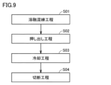
- the method for manufacturing liquid crystal polymer pellets includes a melt-kneading step (S01), an extrusion step (S02), a cooling step (S03), and a cutting step (S04). , prepared in this order.
- melt-kneading process S01
- the liquid crystal polymer raw materials are kneaded while being heated and melted.
- the melt-kneading step can be carried out using, for example, a co-rotating twin-screw extruder. Kneading is carried out, for example, by screws (such as a co-rotating twin-screw extruder).
- the heating temperature is preferably equal to or higher than the melting point of the LCP raw material. When the melting temperature is below the melting point of the LCP raw material, the degree of orientation of the LCP pellets tends to decrease.
- the liquid crystal polymer raw material after the melt-kneading step is extruded into a string shape.
- the liquid crystal polymer raw material is extruded toward the nozzle while being kneaded by the rotation of the screw, and a string-like liquid crystal polymer (string-like material) is extruded from the hole of the nozzle.
- the ratio [V/Q] of the withdrawal speed V (m/min) of the string-like material in the cooling step to the extrusion amount Q (kg/h) of the string-like material in the extrusion step is 5 to 20.
- this ratio (draw ratio) [V/Q] is 5 or more, LCP pellets with an orientation degree of 86% or more can be obtained.
- V/Q exceeds 20, there is a possibility that the string-like object may be cut when the string-like object is taken up, and it is thought that manufacturing may become difficult.
- the extrusion rate (the same amount as the supply rate of the LCP raw material) is preferably 2 to 20 kg/h, more preferably 2 to 10 kg/h. Further, the speed at which the string-like material is taken up in the cooling step is preferably 4 to 70 m/min. More preferably, it is 20 to 60 m/min.
- liquid crystal polymer pellets of this embodiment can be obtained.
- a liquid crystal polymer (LCP) powder according to an embodiment of the present invention includes fibrous particles made of a liquid crystal polymer.
- the fibrous particles contained in the LCP powder are not particularly limited as long as they contain a fibrous portion. Note that the fibrous portion may be linear or may have branches or the like.
- the average aspect ratio of the fibrous particles is preferably 10 or more and 500 or less, more preferably 300 or less, and even more preferably 100 or less. Further, the average diameter of the fibrous particles is more preferably 2 ⁇ m or less, more preferably 1 ⁇ m or less. LCP powder containing such fine fibrous particles cannot be produced by conventionally known methods. Note that, for example, after cutting continuous LCP long fibers produced by the conventional electrospinning method, ultrafine fibers made of LCP usually have an aspect ratio of more than 500.
- the average diameter and average aspect ratio of the fibrous particles contained in the LCP powder are measured by the following method.
- LCP powder to be measured is dispersed in ethanol to prepare a slurry containing 0.01% by mass of LCP powder. At this time, the slurry is prepared such that the water content in the slurry is 1% by mass or less. After dropping 5 to 10 ⁇ L of this slurry onto a slide glass, the slurry on the slide glass is air-dried. Place the LCP powder on a glass slide by air drying the slurry. Next, by observing a predetermined area of the LCP powder placed on the slide glass with a scanning electron microscope, 100 or more image data of particles constituting the LCP powder are collected.
- the above-mentioned area is set according to the size of each LCP particle so that the number of image data is 100 or more.
- the magnification of the scanning electron microscope was changed to 500x, 3000x, or 10000x as appropriate, and the above image was Collect data.
- the lengthwise dimension and widthwise dimension of each particle of the LCP powder are measured using the collected image data. The path that can be taken on one particle of LCP powder photographed in each of the above image data, that is, from one end of the particle, through the approximate center of the particle, to the end opposite to the one end.
- the direction of the straight line connecting both ends of the longest route among the routes reached is defined as the longitudinal direction.
- the length of a straight line connecting both ends of the longest route is measured as the longitudinal dimension.
- the size of each particle of LCP powder in the direction orthogonal to the longitudinal direction is measured at three different points in the longitudinal direction.
- the average value of the dimensions measured at these three points is defined as the width direction dimension (fiber diameter) per particle of LCP powder.
- the ratio of the longitudinal dimension to the fiber diameter [longitudinal dimension/fiber diameter] is calculated and used as the aspect ratio of the fibrous particles.
- the average value of the fiber diameters measured for 100 fibrous particles is defined as the average diameter.
- the average value of the aspect ratios measured for 100 fibrous particles is defined as the average aspect ratio.
- fibrous particles may be included in the LCP powder as an aggregate of fibrous particles.
- the axial direction of the LCP molecules constituting the fibrous particles tends to coincide with the longitudinal direction of the fibrous particles.
- destruction occurs between multiple domains formed by bundles of LCP molecules, so that the axial direction of the LCP molecules becomes fibrous. This is thought to be due to the orientation of the particles along the longitudinal direction.
- the bulk density of the LCP powder is preferably 2 to 5 mg/cm 3 .
- the content (number ratio) of particles other than fibrous particles is preferably 20% or less.
- the content (number ratio) of particles other than fibrous particles is preferably 20% or less.
- particles with a maximum height of 10 ⁇ m or less are fibrous particles, and particles with a maximum height of more than 10 ⁇ m are lumpy particles.
- the LCP powder has a D50 (average particle size) value of 13 ⁇ m or less as measured by particle size measurement using a particle size distribution measuring device using a laser diffraction scattering method.
- the liquid crystal polymer powder may further contain a zirconium compound.
- the content of the zirconium compound is preferably 0.001% by weight or more and 0.1% by weight or less, more preferably 0.003% by weight or more and 0.05% by weight or less, based on the total amount of the liquid crystal polymer powder. Since the liquid crystal polymer powder contains a trace amount of a zirconium compound, when light is irradiated in a subsequent treatment step, the light irradiation efficiency can be increased due to the light absorption characteristics of the zirconium compound.
- a zirconium compound refers to a compound containing a zirconium atom.
- the zirconium compound include zirconium acetate, zirconium hydroxide, and zirconium oxide, among which zirconium dioxide (zirconia) is preferably used.
- the zirconium compound contained in the liquid crystal polymer powder is preferably in the form of particles, and the particle size is preferably 1 nm or more and 500 ⁇ m or less, more preferably 10 nm or more and 100 nm or less. It is assumed that the zirconium compound used as the media used in pulverizing the coarsely pulverized liquid crystal polymer is mixed into the zirconium compound during the manufacturing process of the liquid crystal polymer powder.
- a liquid crystal polymer (LCP) film according to one embodiment of the invention includes a liquid crystal polymer.
- the in-plane (XY direction) coefficient of linear expansion (CTE) of the LCP film is preferably 20 ppm/°C or less, more preferably 18 to 20 ppm/°C.
- the linear expansion coefficient of the LCP film is the in-plane (XY direction) linear expansion coefficient of the LCP film measured according to JIS K 7197 by TMA (thermo-mechanical analysis) method.
- the conditions for the TMA method are that the temperature is raised from room temperature to 150° C. at a rate of 10° C./min in a nitrogen atmosphere, the load is 10 g, and the sample shape is a strip (5 mm ⁇ 15 mm).
- LCP films with an in-plane CTE of 20 ppm/°C or less are suitable for circuit boards such as FPC (Flexible Printed Circuit) base materials, diaphragms, organic semiconductor substrates, organic EL substrates, damping plates, etc.
- FPC Flexible Printed Circuit
- the LCP film according to the present embodiment preferably has a small in-plane linear expansion coefficient from the viewpoint of being applicable to the above-mentioned base material.
- the thickness of the LCP film is preferably, for example, 5 ⁇ m or more and 250 ⁇ m or less.
- the LCP film has a water absorption rate of 0.2% by mass or less when soaked in water at room temperature for 24 hours.
- the water absorption rate is 0.2% by mass or less
- the LCP film can be more suitably used as a high frequency circuit board member. If the above-mentioned LCP film having a water absorption rate of 0.2% by mass or less is used as a high-frequency circuit board member, the high-frequency circuit board will be prevented from containing water with an extremely high dielectric constant, and the relative dielectric constant and dielectric constant will be reduced.
- an LCP film made of a liquid crystal polymer in which an amine-derived structure is introduced into the molecular structure has relatively high water absorption, so the water absorption rate is more than 0.2% by mass.
- the LCP film according to this embodiment may have copper foil bonded to at least one surface, or may have copper foil bonded to both surfaces.
- the LCP film according to the present embodiment can be used as a single laminate-like molded product, for example, as FCCL (Flexible Copper Clad Laminates) that can form a circuit by a subtract method.
- FCCL Flexible Copper Clad Laminates
- a fiber mat according to one embodiment of the invention includes a liquid crystal polymer.
- the breaking tension of the fiber mat of this embodiment is preferably 1.0 N/20 mm or more, more preferably 1.2 N/20 mm or more.
- the breaking tension of the fiber mat may be 1.5 N/20 mm or more, or 1.8 N/20 mm or more. According to the present invention, even when heat treatment is performed at a temperature below the melting point of the liquid crystal polymer, the breaking tension can be improved compared to the fiber mat before heat treatment, and the breaking tension is 1.0 N/20 mm or more.
- a fiber mat can be obtained.
- the breaking tension of the fiber mat can be measured using an autograph (AG-XDplus manufactured by Shimadzu Corporation).
- the width of the fiber mat at the time of measurement is 20 mm.
- the overall basis weight of the fiber mat is approximately 30-40 g/m 2 .
- the overall density of the fiber mat is, for example, 0.30 to 0.60 g/m 3 , and the density increases as the fused area of the liquid crystal powder polymer in the thickness direction increases.
- the thickness of the fiber mat is approximately 50 to 100 ⁇ m, and the thickness decreases as the fused area of the liquid crystal powder polymer increases in the thickness direction.
- the method for manufacturing liquid crystal polymer powder according to the present embodiment includes a coarse pulverization step (S11), a fine pulverization step (S12), a coarse particle removal step (S13), and a fiberization step ( S14) in this order.
- LCP pellets are coarsely crushed.
- LCP pellets are coarsely ground with a cutter mill.
- the size of the coarsely pulverized LCP particles is not particularly limited as long as it can be used as a raw material for the pulverization step described below.
- the maximum particle size of the coarsely ground LCP particles is, for example, 3 mm or less.
- the method for manufacturing an LCP film in this embodiment does not necessarily include a coarse pulverization step.
- the LCP pellets can be used as a raw material for the pulverization process, the LCP pellets may be directly used as the raw material for the pulverization process.
- the coarse pulverization step it is preferable to perform the coarse pulverization in a high-pressure dispersed state.
- the number of times the dispersion process is performed is preferably from 1 to 50 times, more preferably from 1 time to 10 times.
- the LCP pellets (after the coarse pulverization step) are pulverized while being dispersed in liquid nitrogen to obtain granular pulverized liquid crystal polymers (finely pulverized LCP).
- the pulverization step it is preferable to use media to pulverize the LCP pellets dispersed in liquid nitrogen.
- the media is, for example, beads.
- zirconia particles can be used as the media.
- the particle size of zirconia used as the media is preferably 0.1 mm or more and 10 mm or less, more preferably 1 mm or more and 8 mm or less.
- a bead mill which has relatively few technical problems.
- An example of an apparatus that can be used in the pulverization process is "LNM-08", a liquid nitrogen bead mill manufactured by Imex Corporation.
- the pulverization method of pulverizing the liquid crystal polymer dispersed in liquid nitrogen is different from the conventional freeze pulverization method.
- the raw material to be crushed is crushed while pouring liquid nitrogen onto the raw material to be crushed and the crushing device itself, but most of the liquid nitrogen is vaporized when the raw material to be crushed is crushed. ing. That is, in the conventional freeze-grinding method, most of the raw material to be crushed is not dispersed in liquid nitrogen at the time the raw material to be crushed is crushed.
- the heat possessed by the raw material to be crushed itself, the heat generated from the crushing device, and the heat generated by the crushing of the raw material to be crushed vaporizes liquid nitrogen in an extremely short time. Therefore, in the conventional freeze-grinding method, the raw material being crushed inside the crushing device is at a temperature much higher than -196° C., which is the boiling point of liquid nitrogen. That is, in the conventional freeze pulverization method, pulverization is carried out under conditions where the internal temperature of the pulverizer is usually -100°C or higher and 0°C or lower. In the conventional freeze-grinding method, even when liquid nitrogen is supplied as much as possible, the temperature inside the grinding device is approximately -150° C. at its lowest.
- the raw material to be crushed is crushed in a state where it is dispersed in liquid nitrogen, so the raw material is crushed in a further cooled state compared to the conventional freeze-grinding method.
- the raw material to be crushed is crushed at a temperature lower than -196°C, which is the boiling point of liquid nitrogen.
- a raw material to be crushed at a temperature lower than -196° C. is crushed, brittle fracture of the raw material to be crushed is repeated, and the crushing of the raw material progresses.
- the rotation speed of freeze-grinding is preferably 1,800 rpm or more, more preferably 2,000 rpm or more, and still more preferably 2,500 rpm or more. By employing such a rotation speed, it becomes easy to obtain granular, finely pulverized liquid crystal polymer having a desired aspect ratio.
- the liquid crystal polymer which has become granular due to brittle fracture in liquid nitrogen, continues to be subjected to impact with media etc. while in the brittle state.
- a plurality of fine cracks are formed in the liquid crystal polymer obtained in the pulverization step in this embodiment from the outer surface to the inside.
- the granular finely pulverized LCP obtained by the pulverizing step has a D50 of 50 ⁇ m or less as measured by a particle size distribution measuring device using a laser diffraction scattering method. Thereby, it is possible to prevent the granular finely pulverized LCP from clogging the nozzle in the fiberization process described below.
- coarse particle removal step coarse particles are removed from the granular finely pulverized LCP obtained in the above pulverization step. For example, by passing granular finely ground LCP through a mesh sieve, the granular finely ground LCP under the sieve is obtained, and by removing the granular finely ground LCP on the sieve, the granular finely ground LCP contained in the granular finely ground LCP is removed. Coarse particles can be removed.
- the type of mesh may be selected as appropriate, and examples of the mesh include meshes with an opening of 53 ⁇ m. Note that the method for manufacturing liquid crystal polymer powder according to the present embodiment does not necessarily have to include the coarse particle removal step.
- the granular finely pulverized LCP is crushed using a wet high-pressure crusher to obtain liquid crystal polymer powder.
- finely ground LCP is dispersed in a dispersion medium for the fiberization process.
- the finely pulverized LCP to be dispersed may not have coarse particles removed, but it is preferable that coarse particles be removed.
- dispersion medium for the fiberization process examples include water, ethanol, methanol, isopropyl alcohol, toluene, benzene, xylene, phenol, acetone, methyl ethyl ketone, diethyl ether, dimethyl ether, hexane, and mixtures thereof.
- the finely pulverized LCP dispersed in the dispersion medium for the fiberization process that is, the finely pulverized LCP in the form of a paste or slurry
- the finely pulverized LCP in the form of a paste or slurry is passed through a nozzle under high pressure.
- the shearing force or collision energy caused by the high-speed flow in the nozzle acts on the liquid crystal polymer, crushing the granular finely ground LCP, and the liquid crystal polymer becomes fibrillated.
- a liquid crystal polymer powder that can be used in a film manufacturing method can be obtained.
- the nozzle diameter of the nozzle is preferably made as small as possible without clogging the nozzle with finely pulverized LCP. Since the granular finely pulverized LCP in this embodiment has a relatively small particle size, the nozzle diameter in the wet high-pressure crusher used in the fiberization process can be made small.
- the nozzle diameter is, for example, 0.2 mm or less.
- a plurality of fine cracks are formed in the granular finely pulverized LCP.
- the dispersion medium enters the inside of the finely pulverized LCP through the fine cracks due to pressurization in the wet high-pressure crushing device.
- the finely pulverized LCP in the form of a paste or slurry passes through the nozzle and is placed under normal pressure, the dispersion medium that has entered the inside of the pulverized LCP expands in a short period of time.
- destruction proceeds from the inside of the finely pulverized LCP.
- the fiberization step of this embodiment by defibrating the granular finely pulverized LCP obtained in the pulverization step of this embodiment, the granular liquid crystal polymer obtained by the conventional freeze-pulverization method is It is possible to obtain a liquid crystal polymer powder that has a lower content of lump particles and is in the form of fine fibers than the liquid crystal polymer powder obtained by crushing the liquid crystal polymer powder.
- the liquid crystal polymer powder may be obtained by crushing the finely pulverized LCP multiple times using a wet high-pressure crushing device. It is preferable that the number of times of crushing by the wet high-pressure crushing device is small. The number of times of crushing by the wet high-pressure crushing device may be, for example, 5 times or less.
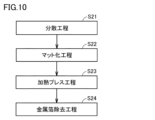
- the method for manufacturing a liquid crystal polymer film according to the present embodiment includes a dispersion step (S21), a matting step (S22), a hot pressing step (S23), and a metal foil removal step (S24). ).
- Dispersion step which is the first step in the method for producing a liquid crystal polymer film
- the above-mentioned liquid crystal polymer powder is dispersed in a dispersion medium to form a paste or slurry.
- the liquid crystal polymer powder can be dispersed in a high viscosity dispersion medium. As a result, a homogeneous liquid crystal polymer film can be produced.
- Examples of the dispersion medium used in the dispersion step include water, terpineol, ethanol, and mixtures thereof.
- terpineol used as a dispersion medium
- a paste-like liquid crystal polymer powder is obtained.
- a mixture of ethanol and water is used as a dispersion medium, a slurry-like liquid crystal polymer is obtained.
- the paste or slurry liquid crystal polymer powder is dried to form a liquid crystal polymer fiber mat.
- the matting step includes, for example, a coating step and a drying step.
- a paste-like liquid crystal polymer powder is applied to metal foil such as copper foil.
- paste-like liquid crystal polymer powder is applied onto metal foil such as copper foil as described above, but instead of the metal foil, a material such as polyimide film, PTFE (polytetrafluoroethylene) film, or glass fiber fabric is used.
- a composite sheet made of a reinforcing material and a heat-resistant resin may also be used. This facilitates industrial production of liquid crystal polymer films.
- the paste-like liquid crystal polymer applied to the copper foil is heated and dried, thereby vaporizing the dispersion medium.
- the dispersion medium may be vaporized by suction.
- the dispersion medium is gradually removed from the paste-like liquid crystal polymer powder, so the overall thickness of the paste-like liquid crystal polymer powder gradually becomes thinner during drying. Therefore, the thickness of the liquid crystal polymer fiber mat is thinner than the total thickness of the pasty liquid crystal polymer formed on the copper foil.
- the total thickness of the paste-like liquid crystal polymer powder is about 700 ⁇ m, and the thickness of the liquid crystal polymer fiber mat is, for example, about 150 ⁇ m.
- the longitudinal direction of the fibrous particles in the LCP powder changes.
- the fibrous particles whose longitudinal direction is along the overall thickness direction of the paste-like liquid crystal polymer powder are arranged so that the longitudinal direction is oriented in the in-plane direction of the copper foil. , lean. Therefore, the fibrous particles in the formed liquid crystal polymer fiber mat have anisotropy in the longitudinal direction.
- a paste-like liquid crystal polymer may be further applied onto the liquid crystal polymer fiber mat formed on the metal foil in the drying step and then dried to vaporize the dispersion medium.
- the matting step may include repeating the coating step and the drying step in this order. Thereby, a liquid crystal polymer fiber mat having a desired basis weight can be obtained.
- the liquid crystal polymer fiber mat in this embodiment is formed such that fibrous particles of liquid crystal polymer powder are entangled with each other. Moreover, the liquid crystal polymer fiber mat has voids between the liquid crystal polymer powders. As mentioned above, the longitudinal direction of the fibrous particles in the liquid crystal polymer powder is generally inclined toward the in-plane direction of the copper foil, so the porosity of the liquid crystal polymer fiber mat is lower than that of a conventional liquid crystal polymer mat that does not contain fibrous particles. It tends to be larger than the liquid crystal polymer mat obtained by matting liquid crystal polymer powder. The porosity is, for example, 80% to 90%.
- a paste-like or slurry-like liquid crystal polymer powder may be formed into a liquid crystal polymer fiber mat by a papermaking method.
- a papermaking method there is no need to use a special dispersion medium (for example, expensive terpineol) used in the above coating process.
- the dispersion medium used in the dispersion process can be recovered and reused. In this way, a liquid crystal polymer film can be produced at low cost by the above-mentioned papermaking method.
- a paste-like or slurry-like liquid crystal polymer powder is formed onto a mesh, a nonwoven microporous sheet, or a woven fabric.
- a liquid crystal polymer fiber mat is then obtained by heating and drying the paste or slurry liquid crystal polymer placed on the mesh.
- the hot pressing step the liquid crystal polymer fiber mat is hot pressed to obtain a liquid crystal polymer film.
- the liquid crystal polymer fiber mat is hot pressed together with the copper foil.
- the hot pressing process also serves as a process of bonding the liquid crystal polymer film and the copper foil to each other, a liquid crystal polymer film with the copper foil bonded can be obtained at a low cost.
- preliminary pressing may be performed at a temperature of 220° C. or lower before performing vacuum hot pressing.
- Preliminary pressing can increase the density of the fiber mat and reduce the coefficient of linear expansion (CTE) of the liquid crystal polymer film.
- the density of the fiber mat is preferably 0.1 to 1.5 g/cm 3 , more preferably 0.3 to 1.4 g/cm 3 .
- the hot pressing step it is preferable to hot press at a temperature approximately 5° C. to 15° C. lower than the melting point of the liquid crystal polymer (raw material) constituting the liquid crystal polymer powder. If hot pressing is performed at a temperature approximately 5° C. to 15° C. lower than the endothermic peak temperature, sintering of the liquid crystal polymers will proceed more easily.
- a release film consisting of a reinforcing material such as a polyimide film, a PTFE film, or a glass fiber fabric and a heat-resistant resin is placed between the press machine used in the hot pressing process and the liquid crystal polymer fiber mat.
- a composite sheet or the like may be sandwiched.
- an additional copper foil may be sandwiched between the press and the liquid crystal polymer fiber mat.
- a liquid crystal polymer film with copper foil bonded on both sides can be obtained.
- a liquid crystal polymer film with copper foil bonded on both sides can be used as a double-sided copper-clad FCCL.
- the external dimension of the liquid crystal polymer film formed by the hot pressing process as viewed from the thickness direction, that is, the planar dimension along the film surface, is approximately the same as that of the liquid crystal polymer fiber mat before hot pressing. Then, by heating pressing, among the fibrous particles of the liquid crystal polymer powder in the liquid crystal polymer fiber mat, the fibrous particles whose longitudinal direction is along the thickness direction of the liquid crystal polymer fiber mat are separated from each other in the in-plane direction of the copper foil. It is heated while being pushed down. Since the liquid crystal polymer constituting the liquid crystal polymer powder has the axial direction of its molecules in the longitudinal direction of the fibrous particles, the axial direction of the molecules of the liquid crystal polymer is also pushed down in the in-plane direction of the copper foil.
- the axial direction of each of the molecules constituting the liquid crystal polymer, except for the molecules constituting the bulk particles, is oriented along the in-plane direction of the liquid crystal polymer film over the thickness direction of the liquid crystal polymer film. Therefore, in the molded liquid crystal polymer film, the main orientation direction of the molecules of the liquid crystal polymer tends to be along the in-plane direction of the copper foil, that is, the in-plane direction of the liquid crystal polymer film.
- the liquid crystal polymer powder in the liquid crystal polymer fiber mat may be joined to each other while the fibrous particles are entangled with each other.
- the liquid crystal polymer in the liquid crystal polymer film has a structure in which each molecule is entangled with each other.
- the fibrous particles have a larger surface area than a spherical liquid crystal polymer having the same volume, the bonding area when the liquid crystal polymer powders are bonded to each other by the hot pressing process also increases.
- the liquid crystal polymer film according to the present embodiment has improved toughness and bending strength. Furthermore, due to the hot pressing process, the thickness of the liquid crystal polymer film is thinner than that of the liquid crystal polymer fiber mat.
- the liquid crystal polymer mat obtained by matting the conventional liquid crystal polymer powder that does not contain fibrous particles as described above contains fibrous particles whose molecular axes are in the longitudinal direction. Not yet. Therefore, even when such a liquid crystal polymer mat is heated and pressed, the axial direction of the molecules constituting the liquid crystal polymer in the liquid crystal polymer film is not pushed down. Therefore, even if a liquid crystal polymer film is manufactured using a conventional liquid crystal polymer powder that does not contain fibrous particles, the main orientation direction of each of the molecules that make up the liquid crystal polymer is along the in-plane direction of the liquid crystal polymer film. There isn't.
- liquid crystal polymer fiber mat obtained by matting conventional liquid crystal polymer powder that does not contain the above-mentioned fibrous particles is heated and pressed
- the bonding area when the liquid crystal polymer powders are bonded to each other is extremely small.
- stress is concentrated at the joints between the liquid crystal polymer powders. Since the bonding area of the bonded portion is small, the liquid crystal polymer film breaks at the bonded portion when external force is applied.
- liquid crystal polymer films manufactured using conventional liquid crystal polymer powders that do not contain fibrous particles have low strength, low toughness, and low bending strength.
- the liquid crystal polymer film cannot be used as a base material for FPC, a diaphragm, or a damping plate.
- Metal foil removal process S24
- the metal foil bonded to the liquid crystal polymer film may be removed by etching or the like. As a result, a single liquid crystal polymer film to which no metal foil is bonded can be obtained.
- a liquid crystal polymer powder containing fibrous particles having an average aspect ratio of 10 or more and 500 or less and an average diameter of 2 ⁇ m or less, which could not be achieved conventionally, is used.
- a liquid crystal polymer film it is possible to obtain a liquid crystal polymer film that has excellent folding strength and the like and can be suitably used as a circuit board.
- LCP films have been produced by a melt extrusion method, a solution casting method, or the like.
- melt extrusion method it was necessary to use an LCP with a relatively low melting point that can be melted in the manufacturing equipment.
- solution casting method it was necessary to use LCP or the like having an amide bond that is dispersible in a solvent.
- LCP film manufacturing method of the present embodiment there is no need to melt LCP, so it is not limited to LCP with a low melting point as described above or LCP that can be dispersed in a solvent. Other LCPs can be used.
- a liquid crystal polymer having a melting point of more than 330°C can be used, and a liquid crystal polymer film having excellent heat resistance can be produced, which includes a liquid crystal polymer having a melting point of more than 330°C.
- the method for manufacturing a fiber mat includes a dispersion step (S31) and a matting step (S32).
- the dispersion step (S31) is the same as the dispersion step (S21) in the method for producing a liquid crystal polymer film.
- the slurry-like liquid crystal polymer powder is formed into a liquid crystal polymer fiber mat by a papermaking method.
- the dispersion medium used in the dispersion process can be recovered and reused, and fiber mats can be produced at low cost.
- FIG. 15 is a diagram showing an example of a matting step of matting liquid crystal polymer powder in the fiber mat manufacturing process. Details of the matting step will be described with reference to FIG. 15.
- a paper machine 100 is used in the matting process.
- the paper machine 100 includes a supply roller 15 that supplies the microporous sheet 10, a take-up roller (not shown) that collects the microporous sheet 10, a paper making wire 20, transport rollers 25 and 26, and a dispersion roller in which the liquid crystal polymer powder is dispersed. It includes a storage section 40 that stores a medium 41, a heating device 50, and a light irradiation device 60.
- the papermaking wire 20 is, for example, a papermaking net of about 80 to 100 mesh. That is, the papermaking wire 20 has a pore diameter of about 150 ⁇ m to 180 ⁇ m.
- the papermaking wire 20 is conveyed by conveyance rollers 25 and 26 arranged in the conveyance direction.
- the conveyance roller 26 is arranged downstream of the conveyance roller 26.
- the papermaking wire 20 is conveyed by these conveyance rollers 25 and 26 so as to pass through the storage section 40 .
- the supply roller 15 supplies the microporous sheet 10 onto the papermaking wire 20.
- the microporous sheet 10 functions as a support for supporting the liquid crystal polymer powder.
- the microporous sheet 10 placed on the papermaking wire 20 is conveyed by the papermaking wire 20 so as to pass through the storage section 40 .
- the microporous sheet 10 that has passed through the storage section 40 is peeled off from the papermaking wire 20 and wound up by a winding roller.
- the microporous sheet 10 has a finer mesh than the papermaking wire 20.
- the microporous sheet 10 preferably has a mesh size of approximately 157 mesh or more. That is, the microporous sheet 10 preferably has a pore diameter of approximately 100 ⁇ m or less. Thereby, fine liquid crystal polymer powder dispersed in the dispersion medium can be collected.
- the microporous sheet 10 has a pore diameter of about 5 ⁇ m to 50 ⁇ m. If the pore diameter of the microporous sheet 10 is too small, drainage properties will be poor and the time required for dewatering will be longer. On the other hand, if the pore diameter of the microporous sheet 10 is too large, fine fibers (fine liquid crystal polymer powder) are difficult to collect, resulting in poor yield.
- microporous sheet 10 When selecting a microporous sheet 10 with variations in pore diameter, this will affect the texture of the fiber mat formed, so if high uniformity is required for the fiber mat, it may be necessary to A knitted mesh is preferred. In other words, as the microporous sheet 10, it is preferable to use a mesh having uniform pore diameters and no deviation in the location of the pores.
- microporous sheet 10 for example, a woven mesh with a pore diameter of 50 ⁇ m or less can be used.
- woven mesh for example, one made of synthetic fibers such as polyester can be used.
- microporous sheet 10 for example, a wet-laid nonwoven fabric having a basis weight of 15 g/m 2 or less may be used.
- a wet-laid nonwoven fabric having a basis weight of 15 g/m 2 or less may be used.
- the wet-laid nonwoven fabric one made of microfibers can be used.
- Microfibers are made of synthetic fibers such as polyester.
- the heating device 50 is arranged on the downstream side of the storage section 40 in the transport direction.
- the heating device 50 heats and dries the liquid crystal polymer powder 30 formed into the microporous sheet 10. As a result, a fiber mat is formed on the microporous sheet 10.
- the light irradiation device 60 is arranged downstream of the heating device 50 in the transport direction.
- the light irradiation device 60 irradiates light toward the fiber mat formed on the microporous sheet 10.
- a flash lamp can be used as the light irradiation device 60.
- the light irradiation device 60 irradiates pulsed light. Since the pulsed light is absorbed by the surface (first main surface 31) of the fiber mat, the support (microporous sheet 10) that supports the fiber mat is not deteriorated by the light irradiation. Therefore, even a material with a lower melting point than the fiber mat can be used as the support, expanding the range of choices for the support. Furthermore, since the fiber mat can be prevented from being fused to the support, the support can be used repeatedly.
- a light irradiation device (PulseForge (registered trademark) 1300 manufactured by NovaCentrix) can be employed.
- the matting step (S32) includes a papermaking step, a peeling step, a drying step, and may further include a light irradiation step.
- the dispersed liquid crystal polymer powder is first formed into a microporous sheet 10 in a forming step. Specifically, the microporous sheet 10 supplied onto the papermaking wire 20 is conveyed by the papermaking wire 20 and passed through the storage section 40 . At this time, the liquid crystal polymer powder dispersed in the dispersion medium 41 stored in the storage section 40 is drawn up into the microporous sheet 10.
- the microporous sheet made from the dispersed liquid crystal polymer powder is peeled off from the paper making wire 20.
- the microporous sheet 10 is transported in a direction different from the papermaking wire 20 by winding the microporous sheet 10 with a winding roller.
- the papermaking wire 20 may be transported in a direction different from that of the microporous sheet 10 by the transport roller 26 .
- the liquid crystal polymer powder formed into the microporous sheet 10 is heated and dried by the heating device 50.
- a fiber mat 30 made of liquid crystal polymer is formed on the microporous sheet 10.
- the first main surface 31 of the fiber mat 30 located on the opposite side to the side where the microporous sheet 10 is located is irradiated with light.
- the liquid crystal polymer powder located on the first main surface 31 side is fused.
- the strength of the fiber mat 30 is improved, and the fiber mat 30 can be transported to the next process without being damaged.
- the density of the fiber mat 30 as a whole is low. Thereby, high air permeability and high collection efficiency can be ensured.
- the fiber mat 30 after being irradiated with light is wound up by the winding roller in the winding process while being placed on the microporous sheet 10.
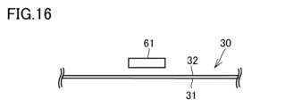
- FIG. 16 is a diagram showing the process of irradiating the second surface of the fiber mat with light.
- the fiber mat 30 whose first main surface 31 is irradiated with light is peeled off from the microporous sheet 10, and the fiber mat 30, which has been irradiated with light on the first main surface 31, is peeled off from the microporous sheet 10, and the fiber mat 30 is separated from the side opposite to the side where the first main surface 31 is located.
- the method may further include the step of irradiating the second main surface 32 of the fiber mat 30 with light. In this step, the fine fibers located on the second main surface 32 side are fused by light irradiation from the light irradiation device 61.
- the light irradiation device 61 one similar to the above-described light irradiation device 60 can be used.
- the fiber mat 30 is irradiated while being transported.
- the strength of the fiber mat 30 can be further improved.
- the liquid crystal polymer powder is fused on the first principal surface 31 side and the fiber mat 30 has sufficient strength. 30 can be peeled off without damaging it.
- the fiber mat 30 produced in this manner may be used as it is, or may be subjected to the hot pressing step S23 of the method for producing a liquid crystal polymer film.
- the fiber mat 30 is irradiated with light.
- the light irradiation efficiency may be increased due to the light absorption characteristics of the zirconium compound. By increasing the light irradiation efficiency, it may be possible to improve the breaking tension of the fiber mat.
- a liquid crystal polymer film and a fiber mat are irradiated with a laser to form through holes or cut portions.
- a laser for example, a commercially available laser processing machine using CO 2 or a semiconductor as a laser oscillator can be used.
- CO 2 or a semiconductor as a laser oscillator
- By changing the lens of the laser processing machine it is possible to change the beam spot diameter of the laser beam. In order to perform fine processing, it is preferable that the beam spot diameter is small.
- the irradiation efficiency of laser irradiation is improved and the formation of through holes is facilitated.
- Example 1 Manufacture of liquid crystal polymer pellets
- uniaxially oriented liquid crystal polymer pellets were first produced as LCP pellets. Specifically, pellets were produced by a melt extrusion method under the following conditions.
- the liquid crystal polymer raw material used to produce the LCP pellets had a melting point of 320°C and a melt viscosity (MV) of 32 Pa ⁇ s.
- the liquid crystal polymer raw material is a copolymer of HBA (p-hydroxybenzoic acid) and HNA (4-hydroxy 2-naphthoic acid). Note that, before the melt-kneading step, the LCP raw material powder was dried at 150° C. for 2 hours in order to prevent moisture from being mixed in.
- the melt-kneading process and extrusion process were performed using a co-rotating twin-screw extruder "HK-25D" (manufactured by Parker Corporation).
- the screw of the extruder has a diameter D of 25 mm and a ratio L (length)/D of 41.
- the nozzle of the extruder was a one-hole nozzle with a diameter of 5 mm.
- the LCP raw material was first supplied to the extruder by charging the LCP raw material powder or pellets from the hopper.
- the amount of LCP raw material supplied was 2 kg/h. Note that the LCP raw material was supplied in a constant amount using a weight type lightweight single shaft feeder "K-CL-SFS-KQx4" (manufactured by Coperion Co., Ltd.).
- the supplied LCP raw material was melt-kneaded by the screw, and string-like LCP was extruded from the nozzle.
- the screw rotation speed was 200 rpm
- the melt extrusion temperature (the temperature at which the molten LCP raw material was extruded from the nozzle hole) was 320°C.
- the extrusion rate (Q) of the string material is basically the same as the supply rate of the LCP raw material, which is 2 kg/h.
- the string-like material (strand) obtained in the extrusion step was cooled in water by passing it through water while taking it.
- the string-like material take-up speed (V) was 39.3 m/min. Note that the ratio (V/Q) of the withdrawal speed (V) to the extrusion amount (Q) is approximately 19.6. Further, the horizontal distance over which the string-like object was immersed in water was 105 cm.
- trapezoidal columnar LCP pellets were obtained by cutting the string-like material after the cooling process.
- the upper base of the trapezoid was 2 mm
- the lower base was 3 mm
- the height (thickness) was 1 mm
- the length of the trapezoidal pillar was 4 mm.
- the coarsely pulverized liquid crystal polymer was pulverized using a liquid nitrogen bead mill (manufactured by Imex, LNM-08, vessel capacity: 0.8 L). Specifically, 400 mL of media and 30 g of coarsely pulverized liquid crystal polymer were placed in a vessel and pulverized at a rotational speed of 2000 rpm (disc circumferential speed: 5.2 m/s) for 120 minutes. As the media, beads made of zirconia (ZrO 2 ) with a diameter of 5 mm were used. In addition, in a liquid nitrogen bead mill, a wet pulverization process is performed in a state where the coarsely pulverized liquid crystal polymer is dispersed in liquid nitrogen. In this way, by pulverizing the coarsely pulverized liquid crystal polymer with a liquid nitrogen bead mill, a granular finely pulverized liquid crystal polymer was obtained.
- a liquid nitrogen bead mill manufactured by Imex, LNM-
- the particle size of this finely pulverized liquid crystal polymer was measured.
- the finely ground liquid crystal polymer dispersed in a dispersion medium was subjected to ultrasonic treatment for 10 seconds, and then set in a particle size distribution measuring device (manufactured by Horiba, Ltd., LA-950) using a laser diffraction scattering method. The particle size was measured. Note that ethanol was used as the dispersion medium.
- the dispersion obtained by dispersing the finely ground liquid crystal polymer in ethanol is sieved through a mesh with an opening of 100 ⁇ m to remove coarse particles contained in the finely ground liquid crystal polymer and collect the finely ground liquid crystal polymer that has passed through the mesh. did.
- the yield of finely pulverized liquid crystal polymer obtained by removing the coarse particles was 75% by mass.
- the finely pulverized liquid crystal polymer from which coarse particles had been removed was dispersed in a 20% by mass ethanol aqueous solution.
- the ethanol slurry in which the finely pulverized liquid crystal polymer was dispersed was repeatedly crushed five times using a wet high-pressure crusher under conditions of a slit chamber nozzle diameter of 0.2 mm and a pressure of 200 MPa to form fibers.
- a wet high-pressure crushing device a high-pressure dispersion machine (Nano Veita manufactured by Yoshida Kikai Kogyo Co., Ltd.) was used. As a result, a liquid crystal polymer powder dispersed in an ethanol aqueous solution was obtained.
- liquid crystal polymer web liquid crystal polymer fiber mat
- terpineol in an amount 20 times the mass of the dispersed liquid crystal polymer powder was added to the ethanol aqueous solution in which the liquid crystal polymer powder was dispersed. Then, by heating the aqueous solution while stirring, water and ethanol were vaporized and removed. As a result, a liquid crystal polymer powder dispersed in terpineol was obtained. That is, the liquid crystal polymer powder was made into a paste by dispersing it in terpineol, which is a dispersion medium.
- a paste-like liquid crystal polymer was applied onto the roughened surface of a 12 ⁇ m thick electrolytic copper foil (manufactured by Furukawa Electric Co., Ltd., FWJ-WS-12). Then, by heating the electrolytic copper foil coated with the paste-like liquid crystal polymer powder to 130°C on a hot plate, terpineol, which is a dispersion medium, is vaporized, and the paste-like liquid crystal polymer powder on the electrolytic copper foil is heated. Dry. In this way, a thin liquid crystal polymer fiber mat was formed on the electrolytic copper foil.
- the paste-like liquid crystal polymer powder was further applied onto this thin liquid crystal polymer fiber mat.
- the applied paste-like liquid crystal polymer powder was dried in the same manner as when the applied paste-like liquid crystal polymer was dried. In this way, by repeating the above application and drying several times, a liquid crystal polymer fiber mat whose basis weight was adjusted to 35 g/m 2 was formed on the electrolytic copper foil.
- the liquid crystal polymer fiber mat formed on the electrolytic copper foil was hot pressed together with the electrolytic copper foil using a vacuum high temperature press device (manufactured by Kitagawa Seiki Co., Ltd., KVHC). Specifically, first, a release film was laminated on the side opposite to the electrolytic copper foil side of the liquid crystal polymer fiber mat formed on the electrolytic copper foil. As the release film, a polyimide film (manufactured by DuPont-Toray, Kapton (registered trademark) 100H) was used. Then, the liquid crystal polymer fiber mat with the release film laminated thereon was set in a vacuum heating press machine at room temperature.
- a vacuum high temperature press device manufactured by Kitagawa Seiki Co., Ltd., KVHC.
- the temperature was raised to 305° C. at a rate of 7° C./min. After reaching 305°C, while maintaining the temperature at 305°C, the liquid crystal polymer film was pressed together with the release film and the electrolytic copper foil at a pressing pressure of 6 Mpa for 5 minutes. Note that the press size (length of one side of the square liquid crystal polymer fiber mat) was 170 mm. After the hot pressing was completed, the release film was removed to obtain a liquid crystal polymer film formed on the electrolytic copper foil.
- the electrolytic copper foil that had been bonded to the liquid crystal polymer film was removed by etching using an aqueous solution of ferric chloride. Thereby, a liquid crystal polymer film was obtained.
- the thickness of the liquid crystal polymer film was 25 ⁇ m.
- Example 2 the supply amount of the LCP raw material (the amount of extrusion of the string material) was 3 kg/h, and the take-up speed was 42.3 m/min.
- LCP pellets and LCP powder were produced in the same manner as in Example 1, and an LCP film was obtained.
- Example 3 An LCP raw material (a copolymer of HBA (p-hydroxybenzoic acid) and HNA (4-hydroxy 2-naphthoic acid)) having a MV of 33 (melting point of 320° C.) was used. Further, the supply amount of the LCP raw material (the amount of extrusion of the string material) was 4 kg/h, and the take-up speed was 26.3 m/min. In other respects, LCP pellets and LCP powder were produced in the same manner as in Example 2, and an LCP film was obtained.
- HBA p-hydroxybenzoic acid
- HNA 4-hydroxy 2-naphthoic acid
- Example 4 An LCP raw material (a copolymer of HBA (p-hydroxybenzoic acid) and HNA (4-hydroxy 2-naphthoic acid)) having a MV of 32 (melting point of 320° C.) was used. Further, the take-up speed was 20.3 m/min. In other respects, LCP pellets and LCP powder were produced in the same manner as in Example 3, and an LCP film was obtained.
- HBA p-hydroxybenzoic acid
- HNA 4-hydroxy 2-naphthoic acid
- Comparative example 1 In Comparative Example 1, the supply amount of the LCP raw material (the extrusion amount of the string-like material) was 8 kg/h. In other respects, LCP pellets and LCP powder were produced in the same manner as in Example 2, and an LCP film was obtained. Note that the shape of the LCP pellet of Comparative Example 1 was close to an elliptical cylinder with a major axis of 4 mm, a minor axis of 1 mm, and a length of 4 mm.
- the degree of orientation of the liquid crystal polymer pellets according to each of the examples and comparative examples was measured by wide-angle X-ray scattering (WAXS). Specifically, the WAXS analysis was performed using the wide-angle measurement mode of a small-angle X-ray scattering analyzer ("NANOPIX" manufactured by Rigaku). The distance between the liquid crystal polymer pellet sample and the detector was 80 mm, and the distance was calibrated using Si. Irradiation of the sample with X-rays and detection of scattered X-rays by a detector were performed in a vacuum environment. A beam stopper was placed between the sample and the detector to block some of the scattered X-rays from reaching the detector. The degree of orientation was calculated from the circular integral at the strongest peak of the scattering intensity of the scattered X-rays.
- WAXS wide-angle X-ray scattering
- the solidified bulk density of the liquid crystal polymer pellets according to each of the examples and comparative examples was measured. Specifically, first, a measuring cylinder (maximum scale: 100 mL) was filled with LCP pellets up to a scale of 100 mL, and the weight of the filled LCP pellets was measured. Thereafter, tapping was performed 10 times (vibration of the graduated cylinder up and down), and the volume of the LCP pellet after tapping was confirmed on the scale of the graduated cylinder.
- the solidified bulk density was calculated from the following formula.
- Solidified bulk density [Weight of filled LCP pellets (g)] / [Volume of LCP pellets after tapping (cm 3 )]
- the measurement results of the solidified bulk density of the liquid crystal polymer pellets are shown in Table 1 and FIG. 2.
- the in-plane linear expansion coefficients of the liquid crystal polymer films according to each of the examples and comparative examples were measured. Specifically, the in-plane (XY directions) linear expansion coefficient of the liquid crystal polymer film was measured by TMA (thermo-mechanical analysis) according to JIS K 7197. The conditions for TMA were that the temperature was raised from room temperature to 150° C. at a rate of 10° C./min under a nitrogen atmosphere, the load was 10 g, and the sample shape was a strip (5 mm ⁇ 15 mm). Table 1 and FIG. 1 show the measurement results of the coefficient of linear expansion (CTE) of the liquid crystal polymer film.
- CTE coefficient of linear expansion
- liquid crystal polymer films of Examples 1 to 4 produced using liquid crystal polymer pellets with a degree of orientation of 86% or more were manufactured using liquid crystal polymer pellets with a CTE of 20 ppm/°C or less and a degree of orientation of less than 86%. It can be seen that the CTE is smaller than that of the liquid crystal polymer films of Comparative Examples 1 and 2, which were produced using the same method.
- the finely pulverized LCP made fine by crushing the LCP pellet becomes particles that have a highly oriented state derived from the pellet inside.
- an LCP powder containing fibrous particles of liquid crystal polymer that maintains a highly oriented state can be obtained.
- LCP connections in the direction perpendicular to the arrangement of molecular chains are more easily broken than LCP connections in the direction of the molecular chains. Therefore, the fibrous particles contained in the produced LCP powder tend to be long in the orientation direction and short in the direction perpendicular to the orientation.
- liquid crystal polymers have a negative coefficient of thermal expansion in the direction in which the molecules are oriented. Therefore, when an LCP film is produced using such an LCP powder, an LCP film having a small in-plane (plane direction) linear expansion coefficient (thermal expansion coefficient) can be obtained.
- liquid crystal polymer film By producing a liquid crystal polymer film using liquid crystal polymer pellets with a high degree of orientation and a high bulk density, a liquid crystal polymer film composed of highly oriented fine fibers (fibrous particles) is formed. It is believed that the in-plane CTE of the liquid crystal polymer film is reduced.
- LCP powder and LCP film were produced in the same manner as in Example 2, except that only the take-up speed was changed to 4.6 m/min and 46.3 m/min. Regarding these, the solidified bulk density of the LCP pellets, the degree of orientation of the LCP pellets, and the CTE of the LCP film were measured in the same manner as above.
- Figure 12 shows the drawing speed (m/min), the solidified bulk density of LCP pellets (g/cm 3 ), and the degree of orientation of LCP pellets (%) when the drawing speed (draw ratio) was changed in this way. and the CTE (ppm/°C) of the LCP film.
- Example 5 A liquid crystal polymer film of Example 5 was produced using the same raw materials as in Example 4. The only difference from Example 4 is that a preliminary pressing step was performed as a step before hot pressing the liquid crystal polymer fiber mat formed on the electrolytic copper foil together with the electrolytic copper foil using a vacuum high-temperature press device. .
- the preliminary pressing step first, the sheet was pressed at room temperature (7 MPa, 10 sec), and then at 200° C. (7 MPa, 10 sec). Thereafter, the same treatment as in Example 4, specifically, heat treatment was performed using a vacuum high temperature press apparatus (manufactured by Kitagawa Seiki Co., Ltd., KVHC).
- the density of the fiber mats of Examples 4 and 5 was measured by the following method. Further, the coefficient of linear expansion (CTE) of the liquid crystal polymer film of Example 5 was measured in the same manner as that for the liquid crystal polymer film of Example 4 above. Table 2 shows the measurement results.
- the density of the fiber mat was calculated by measuring the weight and thickness of the liquid crystal polymer fiber mat formed on the electrolytic copper foil. Specifically, the weight of the liquid crystal polymer fiber mat was calculated by subtracting the weight of the electrolytic copper foil from the measured weight. Thickness measurement was performed using a micro gauge.
- the main orientation direction of the molecules of the liquid crystal polymer tends to be along the in-plane direction of the copper foil, that is, the in-plane direction of the liquid crystal polymer film.
- the CTE of the liquid crystal polymer film of this embodiment is reduced, and defects such as warpage due to heat shrinkage can be suppressed in the liquid crystal polymer film laminated with copper foil.
- Example 6 Comparative Example 2> (Production of fiber mats of Example 6 and Comparative Example 2) Using the liquid crystal polymer powder of Example 4 (melting point 320°C), water and ethanol were added in required amounts to make 2.2 g of liquid crystal polymer powder per 30 L of 50 wt% ethanol aqueous solution, and the slurry was prepared.
- the liquid crystal polymer powder was formed into a fiber mat using a papermaking method.
- a square sheet machine 2555 manufactured by Kumagai Riki Co., Ltd. was used to machine a liquid crystal polymer powder dispersed in a dispersion medium onto a microporous sheet of polyester mesh with a pore diameter of 11 ⁇ m.
- the fiber mat of Example 6 was formed onto a microporous sheet by heating and drying it at a temperature of 100° C. using a hot air dryer.
- the fiber mat had a basis weight of about 35 g/m 2 .
- the obtained fiber mat was peeled off from the microporous sheet and heat-treated at temperatures of 280°C, 320°C, and 360°C for 1 hour in an N 2 atmosphere.
- An inert oven was used as the heating furnace.
- a fiber mat of Comparative Example 2 was produced using the liquid crystal polymer powder of Comparative Example 1 (melting point 320°C) in the same manner as the fiber mat of Example 6, and heated at 280°C and 320 °C in the same manner as the fiber mat of Example 6. The heat treatment was performed at a temperature of 360°C. The breaking tension of the fiber mats of Example 6 and Comparative Example 2 was measured by the following method. Table 3 shows the measurement results.
- the breaking tension was measured for the fiber mats of Example 6 and Comparative Example 2 that were heat-treated at each temperature.
- the breaking tension was measured by processing the heat-treated fiber mat into a width of 20 mm/length of 100 mm using an autograph (AG-XDplus manufactured by Shimadzu Corporation).
- the measurement conditions were a take-up speed of 0.33 mm/sec, a mode of tension, and an initial length of 50 mm.
- Example 6 From the results shown in Table 3, it was found that in Example 6, a breaking tension of 1.0 N/20 mm or more was obtained even when the heat treatment temperature was 280° C. below the melting point.
- Example 7 Manufacture of fiber mats of Example 7 and Example 8.
- the content W of zirconia in the liquid crystal polymer powder of Example 4 was 0.0219 wt%.
- the zirconia content W was calculated by the following method.
- the zirconia content W calculated by the following method was 0.0005% by weight.
- Example 7 produced using liquid crystal polymer powder without zirconia removal treatment
- Example A fiber mat of No. 8 produced using liquid crystal polymer powder subjected to zirconia removal treatment
- a light irradiation device manufactured by NovaCentrix, PulseForge (registered trademark) 1300
- the entire surface of the mat was subjected to light irradiation treatment.
- the measurement conditions using the ICP emission spectrometer are twin sequential method, high frequency output 1.2 kW, plasma gas flow rate 14 L/min, auxiliary gas flow rate 1.2 L/min, carrier gas flow rate 0.7 L/min, nebulizer coaxial type, measurement
- the direction was horizontal.
- the detection limit was set to 0.02 ⁇ g/L or less.
- the zirconium content per weight of the liquid crystal polymer powder was calculated from the concentration of the ICP solution. The following calculation formula was used, and the amount of Zr (molecular weight 91) was converted into the amount of ZrO 2 (zirconia) (molecular weight 123).
- W (wt%) (zirconium ion concentration of the measured solution (g/L)) x (123 ⁇ 91) x 0.5 L ⁇ 40 g x 100
- Example 7 yielded a fiber mat with higher breaking tension than Example 8.
- the fiber mats of Examples 7 and 8 (set voltage for light irradiation treatment was 230 V) were subjected to laser irradiation and laser processing under the following conditions.
- a KrF excimer laser with a wavelength of 248 nm was generated using the CoMPexPro series (manufactured by Coherent Inc.), and the generated laser was focused onto a 1 mm square area using a reflecting lens and a condensing lens.
- the produced film was placed at the focal length for condensing light, and the laser energy was set so that the energy per irradiation (pulse) was 150 mJ/mm 2 .
- energy for 7 irradiations (pulses) was applied.
- the fiber mat of Example 7 had through holes, and the fiber mat of Example 8 could be cut, although no through holes were formed. From the above results, it was found that in Example 7, in which zirconia was not removed, laser processing could be performed more efficiently.
- a liquid crystal polymer pellet containing a liquid crystal polymer and used as a material for a liquid crystal polymer film A liquid crystal polymer pellet having a degree of orientation measured by wide-angle X-ray scattering of 86% or more.
- the liquid crystal polymer pellet according to ⁇ 1> having a solidified bulk density of less than 0.35 g/cm 3 .
- ⁇ 4> a melt-kneading step of kneading liquid crystal polymer raw materials while heating and melting them; an extrusion step of extruding and molding the liquid crystal polymer raw material after the melt-kneading step into a string shape; a cooling step of cooling the string-like material obtained in the extrusion step in water while taking it; a cutting step of cutting the string-like object after the cooling step,
- the ratio of the take-up speed (m/min) of the string-like material in the cooling step to the extrusion amount (kg/h) of the string-like material in the extrusion step is 5 to 20,
- ⁇ 5> Liquid crystal polymer pellets obtained by the manufacturing method described in ⁇ 4>.
- a method for producing a liquid crystal polymer powder comprising: ⁇ 7> The method for producing liquid crystal polymer powder according to ⁇ 6>, wherein in the pulverization step, the liquid crystal polymer pellets dispersed in the liquid nitrogen are pulverized using media.
- ⁇ 9> ⁇ 8> wherein when a fiber mat is formed using the liquid crystal polymer powder and heat treated at a temperature below the melting point of the liquid crystal polymer powder, the breaking tension of the fiber mat is 1.0 N/20 mm or more.
- a liquid crystal polymer film comprising a liquid crystal polymer, A liquid crystal polymer film having an in-plane linear expansion coefficient of 20 ppm/°C or less.
- a fiber mat containing liquid crystal polymer powder the fiber mat having improved breaking tension by heat treatment at a temperature below its melting point.
- the fiber mat according to ⁇ 13>, wherein the fiber mat has a density of 0.1 to 1.5 g/cm 3 .
- the matting step includes a coating step of applying the liquid crystal polymer powder in the form of a paste or slurry to a copper foil.
- ⁇ 17> The method for producing a liquid crystal polymer film according to ⁇ 16>, wherein in the hot pressing step, the liquid crystal polymer fiber mat is hot pressed together with the copper foil.
- ⁇ 18> The method for producing a liquid crystal polymer film according to any one of ⁇ 15> to ⁇ 17>, further comprising a step of performing preliminary pressing at a temperature of 220° C. or lower before the hot pressing step.
- ⁇ 19> Production of the liquid crystal polymer film according to any one of ⁇ 15> to ⁇ 18>, wherein in the matting step, the liquid crystal polymer powder in paste or slurry form is formed into the liquid crystal polymer fiber mat by a papermaking method.
- Method. ⁇ 20> A liquid crystal polymer film obtained by the production method according to any one of ⁇ 15> to ⁇ 19>.
- Microporous sheet 10 Microporous sheet, 15 Supply roller, 20 Paper making wire, 25, 26 Conveyance roller, 30 Fiber mat, 31 First main surface, 32 Second main surface, 40 Storage section, 41 Dispersion medium, 50 Heating device, 60 Light irradiation Equipment, 100 paper machine.
Landscapes
- Chemical & Material Sciences (AREA)
- Engineering & Computer Science (AREA)
- Health & Medical Sciences (AREA)
- Chemical Kinetics & Catalysis (AREA)
- Medicinal Chemistry (AREA)
- Polymers & Plastics (AREA)
- Organic Chemistry (AREA)
- Mechanical Engineering (AREA)
- Manufacturing & Machinery (AREA)
- Materials Engineering (AREA)
- Processing And Handling Of Plastics And Other Materials For Molding In General (AREA)
Abstract
面内の線膨張係数が小さい液晶ポリマーフィルムを得ること。液晶ポリマーペレットは、液晶ポリマーを含み、液晶ポリマーフィルムの材料として用いられる。液晶ポリマーペレットは、広角X線散乱により測定される配向度が86%以上である。
Description
本発明は、液晶ポリマーペレット、液晶ポリマーペレットの製造方法、液晶ポリマーパウダー、液晶ポリマーパウダーの製造方法、液晶ポリマーフィルム、および、液晶ポリマーフィルムの製造方法に関する。
近年、次世代の高速伝送に対応したプリント配線用の新たな基板材料として、従来に比べて伝送損失が少なく、高周波特性に優れた材料である液晶ポリマー(LCP)が注目されている。LCPは、従来の基板材料であるポリイミド樹脂に比べて、低誘電率特性に優れ、高耐熱性で吸水性も低いため、電気信号などのロスを少なくすることができる。
液晶ポリマーからプリント配線基板等に用いられるLCPフィルムを作製する方法としては、例えば、溶融押出法および溶液キャスト法が知られている。溶融押出法は、溶融させた樹脂を装置から押し出してロールに接触させることで、フィルムを形成する方法である。溶液キャスト法は、LCPペレット等のLCP原料を溶剤に溶解させてなるワニスを平らなベルト上に塗布し、乾燥することにより、LCPフィルムを形成する方法である。
一方、特許文献1には、フィブリル状の液晶ポリマーパウダーの製造方法が記載されている。この方法では、まず、液晶ポリマーの2軸配向フィルムを粉砕することによって液晶ポリマー(LCP)パウダーを得る。次に、得られたLCPパウダーを湿式高圧破砕装置を用いて処理することにより、フィブリル状のLCPパウダーが製造される。このようなフィブリル状のLCPパウダーを原料として用いて、LCPフィルムを製造することもできる。
熱可塑性樹脂のペレットの製造方法としては、吐出出口に設けられた口金を通した溶融ポリマーを紐状に押出し、水浴をくぐらせて冷却して固化し、得られた紐状物をペレット状に切断する方法(コールドカット法)が、最も一般的に用いられている(例えば、特許文献2(特開平10-180753号公報)を参照)。
液晶ポリマーフィルムは、例えば、プリント配線の基板等に用いられる場合にプリント配線の信頼性等を高めるために、表面平滑性(平坦性)が高く、寸法安定性が高い(面内の線膨張係数が小さい)ことが望ましい。ここで、従来の液晶ポリマーフィルムには、面内の線膨張係数の低減化において更なる改善の余地があった。
本発明は、上記の課題に鑑み、面内の線膨張係数が小さい液晶ポリマーフィルムを得ることを目的とする。
本発明の第1局面に基づく液晶ポリマーペレットは、液晶ポリマーを含み、液晶ポリマーフィルムの材料として用いられる。液晶ポリマーペレットは、広角X線散乱により測定される配向度が86%以上である。
本発明の第2局面に基づく液晶ポリマーパウダーの製造方法は、
上記の液晶ポリマーペレットを、液体窒素に分散させた状態で粉砕して、粒状の微粉砕液晶ポリマーを得る微粉砕工程と、
前記微粉砕液晶ポリマーを湿式高圧破砕装置で破砕して、液晶ポリマーパウダーを得る繊維化工程を備える。
上記の液晶ポリマーペレットを、液体窒素に分散させた状態で粉砕して、粒状の微粉砕液晶ポリマーを得る微粉砕工程と、
前記微粉砕液晶ポリマーを湿式高圧破砕装置で破砕して、液晶ポリマーパウダーを得る繊維化工程を備える。
本発明の第3局面に基づく液晶ポリマーフィルムは、液晶ポリマーを含む。液晶ポリマーフィルムの面内の線膨張係数は20ppm/℃以下である。
本発明によれば、液晶ポリマーフィルムの面内の線膨張係数を低減化することができる。
以下、本発明の実施形態について説明するが、本発明はこれらに限定されるものではない。
<液晶ポリマーペレット>
本実施形態に係る液晶ポリマー(LCP)ペレットは、液晶ポリマーを含み、液晶ポリマーフィルムの材料として用いられる。液晶ポリマーペレットは、広角X線散乱(WAXS)により測定される配向度が86%以上である。
本実施形態に係る液晶ポリマー(LCP)ペレットは、液晶ポリマーを含み、液晶ポリマーフィルムの材料として用いられる。液晶ポリマーペレットは、広角X線散乱(WAXS)により測定される配向度が86%以上である。
なお、広角X線散乱(WAXS)分析は、サンプルにX線を照射したときに発生する散乱X線を観測する測定手法であり、高分子の結晶構造や配向度(分子鎖の向きが揃う割合)を算出することができる。
本実施形態において、WAXS分析は、小角X線散乱分析装置(Rigaku製「NANOPIX」)の広角測定モードを用いて行われる。サンプルと検出器との間の距離は80mmとし、その距離の校正はSiを用いる。サンプルへのX線の照射および散乱X線の検出器による検出は真空環境下で行われる。サンプルと検出器との間には、ビームストッパーが配置され、散乱X線の一部が検出器に到達しないように遮断される。ペレットの切断断面に対して80°~100°になるようにX線を照射する。配向度は、散乱X線の散乱強度の最強ピークにおける円環積分から算出される。
本実施形態において、WAXS分析は、小角X線散乱分析装置(Rigaku製「NANOPIX」)の広角測定モードを用いて行われる。サンプルと検出器との間の距離は80mmとし、その距離の校正はSiを用いる。サンプルへのX線の照射および散乱X線の検出器による検出は真空環境下で行われる。サンプルと検出器との間には、ビームストッパーが配置され、散乱X線の一部が検出器に到達しないように遮断される。ペレットの切断断面に対して80°~100°になるようにX線を照射する。配向度は、散乱X線の散乱強度の最強ピークにおける円環積分から算出される。
液晶ポリマーペレットの固め嵩密度は、好ましくは0.3g/cm3未満であり、より好ましくは0.09~0.35g/cm3である。この場合、液晶ポリマーペレットの粉砕を容易に行うことが可能である。
固め嵩密度の測定では、まず、メスシリンダー(最大目盛り:100mL)内に、100mLの目盛りまでLCPペレットを充填し、充填されたLCPペレットの重量を測定する。その後、10回のタップ(メスシリンダーの上下振動)を行い、タップ後のLCPペレットの体積をメスシリンダーの目盛りで確認する。固め嵩密度は、下記式から算出される。
固め嵩密度(g/cm3)=〔充填されたLCPペレットの重量(g)〕/〔タップ後のLCPペレットの体積(cm3)〕
固め嵩密度(g/cm3)=〔充填されたLCPペレットの重量(g)〕/〔タップ後のLCPペレットの体積(cm3)〕
液晶ポリマーペレットは、バリ、毛羽立ちなどの繊維状の分岐部を有することが好ましい。液晶ポリマーペレットが繊維状の分岐部を有する場合、液晶ポリマーペレットを低温粉砕により短時間で粉砕することが可能である。
液晶ポリマーは、例えば、サーモトロピック液晶ポリマーである。また、液晶ポリマーの分子は、分子軸の軸方向に負の線膨張係数(熱膨張係数:CTE)を有しており、分子軸の径方向に正のCTEを有している。なお、液晶ポリマーはアミド結合を有していないことが好ましい。
アミド結合を有していないサーモトロピック液晶ポリマーとしては、例えば、1型液晶ポリマーと呼ばれる融点が高く、CTEが低いパラヒドロキシ安息香酸とテレフタル酸とジヒドロキシビフェニルとの共重合体(パラヒドロキシ安息香酸とエチレンテレフタレートとのブロック共重合体)、または、1.5型(もしくは3型)と呼ばれる1型液晶ポリマーと2型液晶ポリマーとの間の融点を有するパラヒドロキシ安息香酸と2,6-ヒドロキシナフトエ酸との共重合体(ブロック共重合体)が挙げられる。
液晶ポリマーの融点は、280℃より高いことが好ましく、300℃以上であることがより好ましい。ここでいう「融点」とは、LCPを不活性雰囲気下で400℃まで加熱した後、40℃/min以上の降温速度で常温まで冷却し、再び40℃/minの昇温速度で加熱しつつ示差走査熱量計を用いて測定したときの「吸熱ピーク温度」を意味する。LCPの融点(吸熱ピーク温度)が300℃を超えている場合、耐熱性に優れたLCPフィルムを得ることができる。
なお、液晶ポリマーの融点は、LCPフィルムを成形するという観点から、LCPの分解温度より低いことが好ましく、例えば400℃以下であることが好ましい。
液晶ポリマーの溶融粘度は、好ましくは15~79Pa・sである。これにより、LCPフィルムの面内のCTEをさらに向上させることができる。
なお、液晶ポリマーの溶融粘度は、以下の測定条件で、JIS K7199に準じて、東洋精機製作所製キャピログラフによって測定される。
温度:(融点+25℃)
せん断速度:1000Sec-1
キャピラリー:長さ20mm/直径1mm
温度:(融点+25℃)
せん断速度:1000Sec-1
キャピラリー:長さ20mm/直径1mm
<液晶ポリマーペレットの製造方法>
以下、本発明の一実施形態に係る液晶ポリマーペレットの製造方法について説明する。
以下、本発明の一実施形態に係る液晶ポリマーペレットの製造方法について説明する。
図9に示されるように、本実施形態に係る液晶ポリマーペレットの製造方法は、溶融混練工程(S01)と、押し出し工程(S02)と、冷却工程(S03)と、切断工程(S04)とを、この順で備える。
(溶融混練工程:S01)
溶融混練工程においては、液晶ポリマー原料を加熱溶融しながら混練する。
溶融混練工程は、例えば、同方向回転2軸押し出し機を用いて実施することができる。混練は、例えば、(同方向回転2軸押し出し機などの)スクリューによって実施される。加熱の温度(溶融温度)は、LCP原料の融点と同程度以上であることが好ましい。溶融温度がLCP原料の融点未満である場合、LCPペレットの配向度が低下する傾向がある。
溶融混練工程においては、液晶ポリマー原料を加熱溶融しながら混練する。
溶融混練工程は、例えば、同方向回転2軸押し出し機を用いて実施することができる。混練は、例えば、(同方向回転2軸押し出し機などの)スクリューによって実施される。加熱の温度(溶融温度)は、LCP原料の融点と同程度以上であることが好ましい。溶融温度がLCP原料の融点未満である場合、LCPペレットの配向度が低下する傾向がある。
(押し出し工程:S02)
押し出し工程においては、溶融混練工程後の液晶ポリマー原料を紐状に押し出し成形する。具体的には、例えば、液晶ポリマー原料がスクリューの回転によって混練されながらノズル方向に押し出され、ノズルの孔から紐状の液晶ポリマー(紐状物)が押し出される。
押し出し工程においては、溶融混練工程後の液晶ポリマー原料を紐状に押し出し成形する。具体的には、例えば、液晶ポリマー原料がスクリューの回転によって混練されながらノズル方向に押し出され、ノズルの孔から紐状の液晶ポリマー(紐状物)が押し出される。
(冷却工程:S03)
冷却工程においては、押し出し工程で得られた紐状物を引き取りながら水中で冷却する。
冷却工程においては、押し出し工程で得られた紐状物を引き取りながら水中で冷却する。
ここで、押し出し工程における紐状物の押し出し量Q(kg/h)に対する冷却工程における前記紐状物の引き取り速度V(m/min)の比〔V/Q〕は、5~20である。この比(ドロー比)〔V/Q〕が5以上であることにより、配向度が86%以上のLCPペレットを得ることができる。なお、V/Qが20を超える場合、紐状物の引き取りによって紐状物が切断される可能性があり、製造が困難になる可能性があると考えられる。
なお、前記押し出し量(LCP原料の供給量と同じ量)は、好ましくは2~20kg/h、より好ましくは2~10kg/hである。また、冷却工程における前記紐状物の引き取り速度は、好ましくは4~70m/minである。より好ましくは20~60m/minである。
(切断工程:S04)
切断工程においては、冷却工程後の紐状物を切断する。
切断工程においては、冷却工程後の紐状物を切断する。
以上の工程によって、本実施形態の液晶ポリマーペレットを得ることができる。
<液晶ポリマーパウダー>
本発明の一実施形態に係る液晶ポリマー(LCP)パウダーは、液晶ポリマーからなる繊維状の粒子を含む。
本発明の一実施形態に係る液晶ポリマー(LCP)パウダーは、液晶ポリマーからなる繊維状の粒子を含む。
(繊維状の粒子)
LCPパウダーに含まれる繊維状の粒子は、繊維状の部分を含んでいれば特に限定されない。なお、繊維状の部分は直鎖状であってもよく、分岐等を有していてもよい。
LCPパウダーに含まれる繊維状の粒子は、繊維状の部分を含んでいれば特に限定されない。なお、繊維状の部分は直鎖状であってもよく、分岐等を有していてもよい。
該繊維状の粒子の平均アスペクト比は、好ましくは10以上500以下であり、より好ましくは300以下であり、さらに好ましくは100以下である。また、該繊維状の粒子の平均径は、より好ましくは2μm以下であり、より好ましくは1μm以下である。
このような微細な繊維状の粒子を含むLCPパウダーは、従来公知の方法では製造できない。なお、例えば、従来のエレクトロスピニング法で製造された連続したLCPの長繊維をカットした後の、LCPからなる極細の繊維は、通常、アスペクト比が500超になる。
このような微細な繊維状の粒子を含むLCPパウダーは、従来公知の方法では製造できない。なお、例えば、従来のエレクトロスピニング法で製造された連続したLCPの長繊維をカットした後の、LCPからなる極細の繊維は、通常、アスペクト比が500超になる。
なお、LCPパウダーに含まれる繊維状の粒子の平均径および平均アスペクト比は、以下の方法によって測定される。
(繊維状の粒子の平均径および平均アスペクト比の測定)
測定対象となるLCPパウダーをエタノールに分散させて、0.01質量%のLCPパウダーを含有するスラリーを作製する。このとき、スラリー中の水分の含有率が1質量%以下となるようにスラリーを作製する。そして、このスラリーをスライドガラス上に5~10μL滴下した後、スライドガラス上のスラリーを自然乾燥させる。スラリーを自然乾燥させることにより、スライドガラス上にLCPパウダーを配置する。
次に、スライドガラス上に配置されたLCPパウダーの所定の領域を、走査型電子顕微鏡で観察することにより、LCPパウダーを構成する粒子の画像データを100以上採集する。なお、画像データの採集においては、画像データの数が100以上となるように、LCPの一粒子あたりの大きさに応じて上記領域を設定する。また、LCPの各粒子について、画像データの採取の漏れまたは測定誤差の発生を抑制するため、走査型電子顕微鏡の拡大倍率を500倍、3000倍、または、10000倍に適宜変更して、上記画像データを採取する。
次に、採取した上記各画像データを用いて、LCPパウダーの各粒子の長手方向寸法と、幅方向寸法とを測定する。
上記画像データの各々に撮影されたLCPパウダーの一粒子上でとり得る経路、すなわち、当該粒子の一の端部から当該粒子の略中央を通って当該一の端部の反対側の端部に到達する経路のうち、最も長い経路の両端を結ぶ直線の方向を長手方向と定義する。そして、当該最も長い経路の両端を結ぶ直線の長さを、長手方向寸法として測定する。
また、LCPパウダーの一粒子の、上記長手方向において互いに異なる3箇所の地点で、長手方向に直交する方向における粒子の寸法を測定する。この3箇所の地点で測定された寸法の平均値を、LCPパウダーの一粒子あたりの幅方向寸法(繊維径)とする。
さらに、繊維径に対する長手方向寸法の比〔長手方向寸法/繊維径〕を算出して、繊維状の粒子のアスペクト比とする。
そして、100個の繊維状の粒子について測定された繊維径の平均値を平均径とする。
また、100個の繊維状の粒子について測定されたアスペクト比の平均値を平均アスペクト比とする。
なお、上記繊維状の粒子は、繊維状の粒子が凝集した凝集体として、LCPパウダーに含まれていてもよい。
また、上記繊維状の粒子は、繊維状の粒子を構成するLCP分子の軸方向と、繊維状の粒子の長手方向とが互いに一致する傾向がある。なお、後述の繊維化工程を経てLCPパウダーが製造される場合、LCP分子が束になることで形成されている複数のドメイン同士の間で破壊が生じることで、LCP分子の軸方向が繊維状の粒子の長手方向に沿って配向するためであると考えられる。
LCPパウダーの嵩密度は、好ましくは2~5mg/cm3である。
LCPパウダーにおいては、繊維状の粒子以外の粒子(実質的に繊維化されていない塊状粒子)の含有率(個数比率)が20%以下であることが好ましい。例えば、LCPパウダーを平面上に載置したときに最大高さが10μm以下の粒子が繊維状の粒子であり、最大高さが10μmより大きい粒子が塊状粒子である。
LCPパウダーは、レーザ回折散乱法による粒子径分布測定装置を用いた粒度測定により測定されるD50(平均粒径)の値が、13μm以下であることが好ましい。
液晶ポリマーパウダーは、ジルコニウム化合物をさらに含んでいてもよい。ジルコニウム化合物は、前記液晶ポリマーパウダーの全量に対して、好ましくは0.001重量%以上0.1重量%以下、さらに好ましくは0.003重量%以上0.05重量%以下含まれる。液晶ポリマーパウダーは、微量のジルコニウム化合物を含むことで、後段の処理工程で光を照射する場合には、ジルコニウム化合物による光の吸収特性により、光の照射効率を上げることができる。
ジルコニウム化合物とは、ジルコニウム原子を含有する化合物をいう。ジルコニウム化合物としては、例えば、酢酸ジルコニウム、水酸化ジルコニウム、酸化ジルコニウムなどが挙げられ、中でも、二酸化ジルコニウム(ジルコニア)が好ましく用いられる。液晶ポリマーパウダーに含まれるジルコニウム化合物は好ましくは粒子状であり、粒径は、好ましくは1nm以上500μm以下であり、より好ましくは10nm以上100nm以下である。ジルコニウム化合物は、液晶ポリマーパウダーの製造過程で、粗粉砕液晶ポリマーの粉砕時に用いられるメディアとして用いられるものが混入することが想定される。
<液晶ポリマーフィルム>
本発明の一実施形態に係る液晶ポリマー(LCP)フィルムは、液晶ポリマーを含む。
本発明の一実施形態に係る液晶ポリマー(LCP)フィルムは、液晶ポリマーを含む。
LCPフィルムの面内(XY方向)の線膨張係数(CTE)は、好ましくは20ppm/℃以下であり、より好ましくは18~20ppm/℃である。
LCPフィルムの線膨張係数は、TMA(熱機械分析)法により、JIS K 7197に準じて測定されるLCPフィルムの面内(XY方向)の線膨張係数である。TMA法の条件は、窒素雰囲気下で室温から150℃まで10℃/分で昇温し、荷重は10gであり、サンプル形状は短冊状(5mm×15mm)である。
LCPフィルムの線膨張係数は、TMA(熱機械分析)法により、JIS K 7197に準じて測定されるLCPフィルムの面内(XY方向)の線膨張係数である。TMA法の条件は、窒素雰囲気下で室温から150℃まで10℃/分で昇温し、荷重は10gであり、サンプル形状は短冊状(5mm×15mm)である。
このように、面内のCTEが20ppm/℃以下であるLCPフィルムは、回路基板としてFPC(Flexible Printed Circuit)用の基材、振動板、有機半導体基板、有機EL基板、制振板などに好適に使用できる。すなわち、本実施形態に係るLCPフィルムは、上述した基材などに適用可能とするという観点から、面内の線膨張係数が小さいことが好ましい。
LCPフィルムの厚さは、例えば5μm以上250μm以下であることが好ましい。
LCPフィルムは、常温の水に24時間浸したときの吸水率が0.2質量%以下であることが好ましい。このように、上記吸水率が0.2質量%以下であれば、LCPフィルムは、高周波用の回路基板部材としてより好適に使用できる。上記吸水率が0.2質量%以下であるLCPフィルムを高周波用の回路基板部材として用いれば、高周波用の回路基板が、誘電率の極めて高い水を含むことが抑制され、比誘電率および誘電正接の増加に伴う誘電体損の増加を抑制することができ、さらに、誘電率の変動による特性インピーダンスの不整合およびそれに伴う伝送損失の発生を抑制できる。なお、例えば、分子構造中にアミン由来の構造が導入された液晶ポリマーからなるLCPフィルムは、吸水性が比較的高いため、吸水率は0.2質量%超となる。
本実施形態に係るLCPフィルムは、少なくとも一方の面に銅箔が接合されていてもよく、両面に銅箔が接合されていてもよい。この場合、本実施形態に係るLCPフィルムは、一つのラミネート状の成形体として、例えばサブトラクト法による回路形成が可能なFCCL(Flexible Copper Clad Laminates)として使用できる。
<繊維マット>
本発明の一実施形態に係る繊維マットは、液晶ポリマーを含む。本実施形態の繊維マットの破断張力は、1.0N/20mm以上であることが好ましく、1.2N/20mm以上であることがより好ましい。繊維マットの破断張力は、1.5N/20mm以上であってもよいし、1.8N/20mm以上であってもよい。本発明によると、液晶ポリマーの融点以下の温度で熱処理がなされた場合であっても、熱処理前の繊維マットと比較して破断張力を向上させることができ、破断張力が1.0N/20mm以上である繊維マットを得ることができる。
本発明の一実施形態に係る繊維マットは、液晶ポリマーを含む。本実施形態の繊維マットの破断張力は、1.0N/20mm以上であることが好ましく、1.2N/20mm以上であることがより好ましい。繊維マットの破断張力は、1.5N/20mm以上であってもよいし、1.8N/20mm以上であってもよい。本発明によると、液晶ポリマーの融点以下の温度で熱処理がなされた場合であっても、熱処理前の繊維マットと比較して破断張力を向上させることができ、破断張力が1.0N/20mm以上である繊維マットを得ることができる。
繊維マットの破断張力は、オートグラフ(島津製作所製AG-XDplus)を用いて測定することができる。この場合において、測定時における繊維マットの幅は、20mmとする。
繊維マットの全体的な坪量は、略30~40g/m2である。繊維マットの全体的な密度は、たとえば、0.30~0.60g/m3であり、厚さ方向における液晶パウダーポリマーの融着領域が大きくなるにつれて、密度が増加する。
繊維マットの厚さは、略50~100μmであり、厚さ方向における液晶パウダーポリマーの融着領域が大きくなるにつれて、厚さは減少する。
<<液晶ポリマーパウダーおよび液晶ポリマーフィルムおよび繊維マットの製造方法>>
以下、本発明の一実施形態に係る液晶ポリマーパウダーおよび液晶ポリマーフィルムの製造方法について説明する。
以下、本発明の一実施形態に係る液晶ポリマーパウダーおよび液晶ポリマーフィルムの製造方法について説明する。
<液晶ポリマーパウダーの製造方法>
図10に示されるように、本実施形態に係る液晶ポリマーパウダーの製造方法は、粗粉砕工程(S11)と、微粉砕工程(S12)と、粗粒除去工程(S13)と、繊維化工程(S14)とを、この順で備える。
図10に示されるように、本実施形態に係る液晶ポリマーパウダーの製造方法は、粗粉砕工程(S11)と、微粉砕工程(S12)と、粗粒除去工程(S13)と、繊維化工程(S14)とを、この順で備える。
(粗粉砕工程:S11)
粗粉砕工程においては、上記のLCPペレットを粗粉砕する。例えば、LCPペレットを、カッターミルで粗粉砕する。粗粉砕されたLCP粒子の大きさは、後述する微粉砕工程の原料として用いることができる限り、特に限定されない。粗粉砕されたLCP粒子の最大粒径は、例えば3mm以下である。
粗粉砕工程においては、上記のLCPペレットを粗粉砕する。例えば、LCPペレットを、カッターミルで粗粉砕する。粗粉砕されたLCP粒子の大きさは、後述する微粉砕工程の原料として用いることができる限り、特に限定されない。粗粉砕されたLCP粒子の最大粒径は、例えば3mm以下である。
本実施形態におけるLCPフィルムの製造方法は、粗粉砕工程を必ずしも備えていなくてもよい。例えば、LCPペレットが微粉砕工程の原料として用いることができるものであれば、LCPペレットを直接微粉砕工程の原料として使用してもよい。粗粉砕工程において、高圧分散させた状態で粗粉砕することが好ましい。分散の処理回数としては、好ましくは1回以上50回以下であり、より好ましくは1回以上10回以下である。粗粉砕工程において高圧分散により粉砕を行うことにより、後段の工程で粒状の微粉砕液晶ポリマーを得やすくなる。
(微粉砕工程:S12)
微粉砕工程においては、(粗粉砕工程後の)LCPペレットを、液体窒素に分散させた状態で粉砕して、粒状の微粉砕液晶ポリマー(微粉砕LCP)を得る。
微粉砕工程においては、(粗粉砕工程後の)LCPペレットを、液体窒素に分散させた状態で粉砕して、粒状の微粉砕液晶ポリマー(微粉砕LCP)を得る。
微粉砕工程においては、メディアを用いて、液体窒素に分散しているLCPペレットを粉砕することが好ましい。メディアは、例えばビーズである。メディアとしては、例えば、ジルコニアの粒子を用いることができる。メディアとして用いられるジルコニアの粒径は、好ましくは0.1mm以上10mm以下であり、より好ましくは1mm以上8mm以下である。本実施形態の微粉砕工程においては、液体窒素を取り扱うという観点から、比較的技術的な問題が少ないビーズミルを用いることが好ましい。微粉砕工程に用いることができる装置としては、例えば、アイメックス社製の液体窒素ビーズミルである「LNM-08」が挙げられる。
本実施形態の微粉砕工程において、液体窒素に液晶ポリマーを分散させた状態で粉砕する粉砕方法は、従来の凍結粉砕法とは異なる。従来の凍結粉砕法は、被粉砕原料および粉砕装置本体に液体窒素を注ぎかけながら、被粉砕原料を粉砕する方法であるが、被粉砕原料が粉砕される時点において液体窒素の大部分は気化している。すなわち、従来の凍結粉砕法では、被粉砕原料が粉砕される時点において被粉砕原料の大部分は液体窒素に分散していない。
従来の凍結粉砕法においては、被粉砕原料自体が有する熱、粉砕装置から発生する熱、および、被粉砕原料の粉砕により発生する熱が、液体窒素をきわめて短時間に気化させる。このため、従来の凍結粉砕法においては、粉砕装置の内部に位置する粉砕中の原料は、液体窒素の沸点である-196℃よりはるかに高い温度となっている。すなわち、従来の凍結粉砕法においては、粉砕装置の内部の温度が通常-100℃以上0℃以下程度の条件下で粉砕を実施している。従来の凍結粉砕法において、可能な限り液体窒素を供給した場合においても、粉砕装置の内部の温度は、最も低い場合でおよそ-150℃である。
このため、従来の凍結粉砕法において、例えば、一軸配向したペレット状の液晶ポリマー(またはその粗粉砕物)を粉砕した場合には、液晶ポリマーの分子軸の軸方向に略平行な面に沿って粉砕が進行するため、アスペクト比が非常に大きく、かつ、繊維径が3μmよりはるかに大きい繊維状の液晶ポリマーが得られると考えられる。すなわち、従来の凍結粉砕法によって、一軸配向したペレット状の液晶ポリマーを粉砕しても、本実施形態で用いられるような粒状の微粉砕液晶ポリマーを得ることができない。
本実施形態においては、被粉砕原料を液体窒素に分散させた状態で粉砕するため、従来の凍結粉砕法と比較して、より一層冷却された状態で原料を粉砕する。具体的には、液体窒素の沸点である-196℃より低い温度で被粉砕原料を粉砕する。-196℃より低い温度の被粉砕原料を粉砕すると、被粉砕原料の脆性破壊が繰り返されることで、原料の粉砕が進行する。これにより、例えば、一軸配向した液晶ポリマーを粉砕した場合においても、液晶ポリマーの分子軸の軸方向に略平行な面での破壊が進行するだけでなく、上記軸方向に交差する面に沿って脆性破壊が進行するため、粒状の微粉砕LCPを得ることができる。
本実施形態の凍結粉砕法において、凍結粉砕の回転数は、好ましくは1800rpm以上であり、より好ましくは2000rpm以上であり、さらに好ましくは2500rpm以上である。このような回転数を採用することにより、所望のアスペクト比を有する粒状の微粉砕液晶ポリマーを得やすくなる。
また、本実施形態における微粉砕工程においては、液体窒素中において、脆性破壊することで粒状となった液晶ポリマーに対して、脆化させた状態のまま、引き続きメディアなどで衝撃を与え続ける。これにより、本実施形態における微粉砕工程において得られた液晶ポリマーには、外側表面から内部にかけて複数の微細なクラックが形成されている。
微粉砕工程により得られる粒状の微粉砕LCPは、レーザ回折散乱法による粒子径分布測定装置で測定したD50が50μm以下であることが好ましい。これにより、下記に示す繊維化工程において粒状の微粉砕LCPがノズルで詰まることを抑制することができる。
(粗粒除去工程:S13)
次に、粗粒除去工程において、上記微粉砕工程で得られた粒状の微粉砕LCPから粗粒を除去する。例えば、粒状の微粉砕LCPをメッシュで篩いにかけることにより、篩下の粒状の微粉砕LCPを得るとともに、篩上の粒状の微粉砕LCPを除去することで、粒状の微粉砕LCPに含まれる粗粒を除去することができる。メッシュの種類は適宜選択すればよいが、メッシュとしては、例えば目開きが53μmのものが挙げられる。なお、本実施形態に係る液晶ポリマーパウダーの製造方法は、粗粒除去工程を必ずしも備えていなくてもよい。
次に、粗粒除去工程において、上記微粉砕工程で得られた粒状の微粉砕LCPから粗粒を除去する。例えば、粒状の微粉砕LCPをメッシュで篩いにかけることにより、篩下の粒状の微粉砕LCPを得るとともに、篩上の粒状の微粉砕LCPを除去することで、粒状の微粉砕LCPに含まれる粗粒を除去することができる。メッシュの種類は適宜選択すればよいが、メッシュとしては、例えば目開きが53μmのものが挙げられる。なお、本実施形態に係る液晶ポリマーパウダーの製造方法は、粗粒除去工程を必ずしも備えていなくてもよい。
(繊維化工程:S14)
次に、繊維化工程において、粒状の微粉砕LCPを湿式高圧破砕装置で破砕して、液晶ポリマーパウダーを得る。繊維化工程においては、まず、微粉砕LCPを繊維化工程用の分散媒に分散させる。分散させる微粉砕LCPは、粗粒が除去されていなくてもよいが、粗粒が除去されていることが好ましい。繊維化工程用の分散媒としては、例えば、水、エタノール、メタノール、イソプロピルアルコール、トルエン、ベンゼン、キシレン、フェノール、アセトン、メチルエチルケトン、ジエチルエーテル、ジメチルエーテル、ヘキサン、または、これらの混合物等が挙げられる。
次に、繊維化工程において、粒状の微粉砕LCPを湿式高圧破砕装置で破砕して、液晶ポリマーパウダーを得る。繊維化工程においては、まず、微粉砕LCPを繊維化工程用の分散媒に分散させる。分散させる微粉砕LCPは、粗粒が除去されていなくてもよいが、粗粒が除去されていることが好ましい。繊維化工程用の分散媒としては、例えば、水、エタノール、メタノール、イソプロピルアルコール、トルエン、ベンゼン、キシレン、フェノール、アセトン、メチルエチルケトン、ジエチルエーテル、ジメチルエーテル、ヘキサン、または、これらの混合物等が挙げられる。
そして、繊維化工程用の分散媒に分散させた状態の微粉砕LCP、すなわち、ペースト状またはスラリー状の微粉砕LCPを、高圧で加圧した状態で、ノズルを通過させる。高圧でノズルを通過させることにより、ノズルでの高速流動による剪断力または衝突エネルギーが液晶ポリマーに作用して、粒状の微粉砕LCPを破砕することで、液晶ポリマーの繊維化が進行し、液晶ポリマーフィルムの製造方法で使用可能な液晶ポリマーパウダーを得ることができる。上記ノズルのノズル径は、高い剪断力または高い衝突エネルギーを与えるという観点から、上記ノズルにおいて微粉砕LCPの詰まりが発生しない範囲で可能な限り小さくすることが好ましい。本実施形態における粒状の微粉砕LCPは粒径が比較的小さいため、繊維化工程において用いる湿式高圧破砕装置におけるノズル径を小さくすることができる。ノズル径は、例えば0.2mm以下である。
本実施形態においては、上述したように、粒状の微粉砕LCPに複数の微細なクラックが形成されている。このため、湿式高圧破砕装置での加圧により、分散媒が、微細なクラックから微粉砕LCPの内部に侵入する。そして、ペースト状またはスラリー状の微粉砕LCPがノズルを通過して常圧下に位置したときに、微粉砕LCPの内部に侵入した分散媒がわずかな時間で膨張する。微粉砕LCP内部に侵入した分散媒が膨張することにより、微粉砕LCPの内部から、破壊が進行する。このため、微粉砕LCPの内部まで繊維化が進み、かつ、液晶ポリマーの分子が一方向に並んでいるドメイン単位に分離する。このように、本実施形態における繊維化工程においては、本実施形態における微粉砕工程で得られた粒状の微粉砕LCPを解繊することで、従来の凍結粉砕法で得られた粒状の液晶ポリマーを破砕することで得られる液晶ポリマーパウダーより、塊状粒子の含有率が低く、かつ、微細繊維状である、液晶ポリマーパウダーを得ることができる。
なお、本実施形態における繊維化工程においては、微粉砕LCPを、複数回、湿式高圧破砕装置で破砕することにより、液晶ポリマーパウダーを得てもよい。湿式高圧破砕装置による破砕の回数は少ないことが好ましい。湿式高圧破砕装置による破砕の回数は、例えば、5回以下であってもよい。
<液晶ポリマーフィルムの製造方法>
図11に示されるように、本実施形態に係る液晶ポリマーフィルムの製造方法は、分散工程(S21)と、マット化工程(S22)と、加熱プレス工程(S23)と、金属箔除去工程(S24)とを備える。
図11に示されるように、本実施形態に係る液晶ポリマーフィルムの製造方法は、分散工程(S21)と、マット化工程(S22)と、加熱プレス工程(S23)と、金属箔除去工程(S24)とを備える。
(分散工程:S21)
液晶ポリマーフィルムの製造方法の最初の工程である分散工程においては、上述の液晶ポリマーパウダーを、分散媒に分散させることでペースト状またはスラリー状にする。このように、本実施形態においては、上述の微細繊維状の液晶ポリマーパウダーを使用するため、液晶ポリマーパウダーを高粘度の分散媒に分散させることができる。ひいては、均質な液晶ポリマーフィルムを製造することができる。
液晶ポリマーフィルムの製造方法の最初の工程である分散工程においては、上述の液晶ポリマーパウダーを、分散媒に分散させることでペースト状またはスラリー状にする。このように、本実施形態においては、上述の微細繊維状の液晶ポリマーパウダーを使用するため、液晶ポリマーパウダーを高粘度の分散媒に分散させることができる。ひいては、均質な液晶ポリマーフィルムを製造することができる。
分散工程において使用される分散媒としては、水、ターピネオールまたはエタノールおよびこれらの混合物などが挙げられる。例えば、分散媒としてターピネオールを用いた場合は、ペースト状の液晶ポリマーパウダーが得られる。分散媒としてエタノールと水との混合物を用いた場合は、スラリー状の液晶ポリマーが得られる。
(マット化工程:S22)
次に、マット化工程において、ペースト状またはスラリー状の液晶ポリマーパウダーを乾燥させて液晶ポリマー繊維マットを形成する。本発明の一実施形態において、マット化工程は、例えば、塗布工程と乾燥工程とを含む。
次に、マット化工程において、ペースト状またはスラリー状の液晶ポリマーパウダーを乾燥させて液晶ポリマー繊維マットを形成する。本発明の一実施形態において、マット化工程は、例えば、塗布工程と乾燥工程とを含む。
塗布工程においては、ペースト状の液晶ポリマーパウダーを銅箔などの金属箔に塗布する。塗布工程においては、上記のように銅箔などの金属箔上に、ペースト状の液晶ポリマーパウダーを塗布するが、金属箔の代わりにポリイミドフィルム、PTFE(polytetrafluoroethylene)フィルム、または、ガラス繊維織物などの補強材と耐熱性樹脂とからなる複合シートなどを用いてもよい。これにより、液晶ポリマーフィルムを工業的に生産することが容易となる。
次に乾燥工程により、銅箔に塗布されたペースト状の液晶ポリマーを加熱乾燥させることで、分散媒を気化させる。分散媒は、吸引により気化させてもよい。上記の加熱乾燥により、銅箔などの金属箔上に液晶ポリマー繊維マットが形成される。
また、乾燥工程においては、ペースト状の液晶ポリマーパウダーから徐々に分散媒が除去されるため、ペースト状の液晶ポリマーパウダーの全体の厚さは乾燥中に徐々に薄くなる。よって、液晶ポリマー繊維マットの厚さは、銅箔上に形成されたペースト状の液晶ポリマー全体の厚さと比較して薄くなる。具体的には、本実施形態において、ペースト状の液晶ポリマーパウダーの全体の厚さは700μm程度であり、液晶ポリマー繊維マットの厚さは、例えば、150μm程度である。
さらに、乾燥中にペースト状のLCPパウダーの全体の厚さが徐々に薄くなるにつれて、LCPパウダー中の繊維状の粒子の長手方向の向きが変化する。具体的には、繊維状の粒子のうち、ペースト状の液晶ポリマーパウダーの全体の厚み方向に沿う方向に長手方向を有する繊維状の粒子が、銅箔の面内方向に長手方向が向くように、傾く。このため、形成された液晶ポリマー繊維マット中の上記繊維状の粒子の長手方向には、異方性がある。
上記マット化工程においては、乾燥工程によって金属箔上に形成された液晶ポリマー繊維マットの上にさらにペースト状の液晶ポリマーを塗布した後、これを乾燥させることで分散媒を気化させてもよい。このように、上記マット化工程においては、塗布工程と乾燥工程とをこの順で繰り返し備えていてもよい。これにより、所望の目付を有する液晶ポリマー繊維マットを得ることができる。
なお、本実施形態における液晶ポリマー繊維マットは、液晶ポリマーパウダーの繊維状の粒子が互いに絡み合うようにして形成される。また、液晶ポリマー繊維マットは、液晶ポリマーパウダー同士の間において空隙を有している。上記のように液晶ポリマーパウダー中の繊維状の粒子の長手方向が、全体的に銅箔の面内方向に向かって傾くため、液晶ポリマー繊維マットの空隙率は、繊維状の粒子を含まない従来の液晶ポリマーパウダーをマット化して得られた液晶ポリマーマットに比べて大きくなる傾向がある。空隙率は、例えば、80%~90%である。
本実施形態におけるマット化工程では、上記塗布工程と乾燥工程とに代えて、抄紙法によって、ペースト状またはスラリー状の液晶ポリマーパウダーを液晶ポリマー繊維マットに形成してもよい。上記抄紙法によれば、上記塗布工程で使用される特殊な分散媒(例えば、高価なターピネオール)を使用しなくてもよい。また、抄紙法においては、分散工程で使用した分散媒を回収して再利用できる。このように、上記抄紙法によって、液晶ポリマーフィルムを廉価に製造できる。
抄紙法を用いたマット化工程においては、具体的には、まず、ペースト状またはスラリー状の液晶ポリマーパウダーをメッシュ、不織布状の微多孔シート、または織物の上に抄き上げる。そして、メッシュ上に配置されたペースト状またはスラリー状の液晶ポリマーを加熱乾燥させることにより、液晶ポリマー繊維マットが得られる。
(加熱プレス工程:S23)
次に、加熱プレス工程においては、液晶ポリマー繊維マットを加熱プレスすることで、液晶ポリマーフィルムを得る。具体的には、加熱プレス工程において、液晶ポリマー繊維マットを、銅箔とともに加熱プレスする。これにより、加熱プレス工程が、液晶ポリマーフィルムと銅箔とを互いに接合させる工程を兼ねるため、銅箔が接合された状態の液晶ポリマーフィルムを、廉価に得ることができる。なお、加熱プレス工程おいて、長時間に加熱する場合は、液晶ポリマー繊維マットを真空加熱プレスすることが好ましい。また、加熱プレス工程においては、真空加熱プレスを行う前に、220℃以下の温度で予備プレスを行ってもよい。予備プレスを行うことにより繊維マットの密度が高くして、液晶ポリマーフィルムの線膨張係数(CTE)を低減することができる。繊維マットの密度は、好ましくは0.1~1.5g/cm3であり、より好ましくは0.3~1.4g/cm3である。
次に、加熱プレス工程においては、液晶ポリマー繊維マットを加熱プレスすることで、液晶ポリマーフィルムを得る。具体的には、加熱プレス工程において、液晶ポリマー繊維マットを、銅箔とともに加熱プレスする。これにより、加熱プレス工程が、液晶ポリマーフィルムと銅箔とを互いに接合させる工程を兼ねるため、銅箔が接合された状態の液晶ポリマーフィルムを、廉価に得ることができる。なお、加熱プレス工程おいて、長時間に加熱する場合は、液晶ポリマー繊維マットを真空加熱プレスすることが好ましい。また、加熱プレス工程においては、真空加熱プレスを行う前に、220℃以下の温度で予備プレスを行ってもよい。予備プレスを行うことにより繊維マットの密度が高くして、液晶ポリマーフィルムの線膨張係数(CTE)を低減することができる。繊維マットの密度は、好ましくは0.1~1.5g/cm3であり、より好ましくは0.3~1.4g/cm3である。
加熱プレス工程においては、液晶ポリマーパウダーを構成する液晶ポリマー(原料)の融点よりおよそ5℃~15℃低い温度で加熱プレスすることが好ましい。上記吸熱ピーク温度よりおよそ5℃~15℃低い温度で加熱プレスすれば、液晶ポリマー同士の焼結が進みやすくなる。
また、加熱プレス工程においては、加熱プレス工程で用いるプレス機と液晶ポリマー繊維マットとの間に、リリースフィルムとしてポリイミドフィルム、PTFEフィルム、または、ガラス繊維織物などの補強材と耐熱性樹脂とからなる複合シートなどを挟んでもよい。
また、ポリイミドフィルムに代えて、プレス機と液晶ポリマー繊維マットとの間に、追加の銅箔を挟んでもよい。この場合、両面に銅箔が接合された液晶ポリマーフィルムを得ることができる。両面に銅箔が接合された液晶ポリマーフィルムは、両面銅貼FCCLとして用いることができる。
加熱プレス工程により成形された液晶ポリマーフィルムの厚さ方向からみた外形寸法、すなわち、フィルム面に沿った平面寸法は、加熱プレスをする前の液晶ポリマー繊維マットと略同一となる。そして、加熱プレスによって、液晶ポリマー繊維マット中の液晶ポリマーパウダーの繊維状の粒子のうち、液晶ポリマー繊維マットの厚み方向に沿う方向に長手方向を有する繊維状の粒子は、銅箔の面内方向に押し倒されつつ加熱される。液晶ポリマーパウダーを構成する液晶ポリマーは、繊維状の粒子の長手方向に分子の軸方向を有しているため、液晶ポリマーの分子の軸方向も、銅箔の面内方向に押し倒される。このため、塊状粒子を構成する分子を除いて、液晶ポリマーを構成する分子の各々の軸方向が、液晶ポリマーフィルムの厚み方向にわたって液晶ポリマーフィルムの面内方向に沿って配向する。したがって、成形された液晶ポリマーフィルムにおいては、液晶ポリマーの分子の主配向方向が、銅箔の面内方向、すなわち、液晶ポリマーフィルムの面内方向に沿う傾向がある。
これにより、本実施形態の液晶ポリマーフィルムでは、面内の線膨張係数が低減されると考えられる。なお、面内の線膨張係数が低い液晶ポリマーフィルムは寸法安定性に優れるという利点がある。
また、液晶ポリマーフィルムに銅箔が貼り合わせられる場合、液晶ポリマーフィルムの線膨張係数を低減して、銅箔の線膨張係数(約18~20ppm/℃)と同程度に合わせることが可能となる。これにより、銅箔が貼り合わせられた液晶ポリマーフィルムにおいて、熱収縮による反り等の不具合が抑制され得る。
また、液晶ポリマーフィルムに銅箔が貼り合わせられる場合、液晶ポリマーフィルムの線膨張係数を低減して、銅箔の線膨張係数(約18~20ppm/℃)と同程度に合わせることが可能となる。これにより、銅箔が貼り合わせられた液晶ポリマーフィルムにおいて、熱収縮による反り等の不具合が抑制され得る。
さらに、液晶ポリマー繊維マット中の液晶ポリマーパウダーは、繊維状の粒子が互いに絡み合ったまま、互いに接合されることがある。これにより、液晶ポリマーフィルム中の液晶ポリマーは、各分子が互いに絡み合った構造を有する。また、上記繊維状の粒子は、これと同じ体積を有する球状の液晶ポリマーと比較して表面積が大きいため、加熱プレス工程により、液晶ポリマーパウダーが互いに接合するときの接合面積も大きくなる。これにより、本実施形態に係る液晶ポリマーフィルムは、靱性および耐折強度が向上する。また、加熱プレス工程により、液晶ポリマーフィルムの厚さは、液晶ポリマー繊維マットと比較して薄くなっている。
なお、上記のような繊維状の粒子を含まない従来の液晶ポリマーパウダーをマット化することにより得られた液晶ポリマーマットには、長手方向に分子軸の軸方向を有する繊維状の粒子が含まれていない。このため、このような液晶ポリマーマットを加熱プレスしても、液晶ポリマーフィルムにおける液晶ポリマーを構成する分子の軸方向は押し倒されることがない。よって、繊維状の粒子を含まない従来の液晶ポリマーパウダーを用いて液晶ポリマーフィルムを製造しても、液晶ポリマーを構成する分子の各々の主配向方向は、液晶ポリマーフィルムの面内方向に沿うことはない。
また、上記繊維状の粒子を含まない従来の液晶ポリマーパウダーをマット化することにより得られた液晶ポリマー繊維マットを加熱プレスしても、液晶ポリマーパウダーが互いに接合されたときの接合面積は極めて小さくなる。このため、繊維状の粒子を含まない従来の液晶ポリマーパウダーを用いて製造された液晶ポリマーフィルムは、外力を受けたときに、液晶ポリマーパウダー同士の接合部分に応力が集中する。そして、当該接合部分の接合面積が小さいため、外力をうけたときに、当該接合部分において液晶ポリマーフィルムの破壊が生じる。このように、繊維状の粒子を含まない従来の液晶ポリマーパウダーを用いて製造された液晶ポリマーフィルムは、強度が弱く、靱性および耐折強度が低くなる。当該液晶ポリマーフィルムは、FPC用の基材、振動板または制振板として用いることはできない。
(金属箔除去工程:S24)
最後に、必要に応じて、液晶ポリマーフィルムに接合した金属箔をエッチングなどにより除去してもよい。これにより、金属箔が接合していない単体の液晶ポリマーフィルムが得られる。
最後に、必要に応じて、液晶ポリマーフィルムに接合した金属箔をエッチングなどにより除去してもよい。これにより、金属箔が接合していない単体の液晶ポリマーフィルムが得られる。
本実施形態の液晶ポリマーフィルムの製造方法によれば、従来は実現できなかった平均アスペクト比が10以上500以下であって、平均径が2μm以下である繊維状の粒子を含む液晶ポリマーパウダーを用いて、液晶ポリマーフィルムを製造することにより、回路基板として好適に用いることの出来る耐折強度等に優れた液晶ポリマーフィルムを得ることができる。
なお、従来は、溶融押出法、溶液キャスト法等でLCPフィルムが作製されていた。溶融押出法の場合は、製造設備で溶融可能な比較的融点が低いLCPを用いる必要があった。また、溶液キャスト法の場合は、溶媒に分散可能なアミド結合を有するLCP等を用いる必要があった。これに対して、本実施形態のLCPフィルムの製造方法においては、LCPを溶融する必要がないため、上述のような融点が低いLCPや、溶媒に分散可能なLCPに限定されることなく、それ以外のLCPを用いることができる。したがって、例えば、融点が330℃超の液晶ポリマーを採用でき、融点が330℃を超えるような液晶ポリマーを含む耐熱性に優れた液晶ポリマーフィルムを製造することができる。
<繊維マットの製造方法>
図14に示すように、本実施形態に係る繊維マットの製造方法は、分散工程(S31)と、マット化工程(S32)とを備える。分散工程(S31)は、液晶ポリマーフィルムの製造方法の分散工程(S21)と同じである。
図14に示すように、本実施形態に係る繊維マットの製造方法は、分散工程(S31)と、マット化工程(S32)とを備える。分散工程(S31)は、液晶ポリマーフィルムの製造方法の分散工程(S21)と同じである。
マット化工程(S32)は、抄紙法によって、スラリー状の液晶ポリマーパウダーを液晶ポリマー繊維マットに成形する。抄紙法においては、分散工程で使用した分散媒を回収して再利用でき、繊維マットを廉価に製造できる。
図15は、繊維マットの製造工程において、液晶ポリマーパウダーをマット化するマット化工程の一例を示す図である。図15を参照して、マット化工程の詳細について説明する。
図15に示すように、マット化工程においては、抄紙機100を用いる。抄紙機100は、微多孔シート10を供給する供給ローラー15、微多孔シート10を回収する巻取ローラー(不図示)、抄紙ワイヤー20、搬送ローラー25,26、上記液晶ポリマーパウダーが分散された分散媒41を貯留する貯留部40、加熱装置50、および光照射装置60を備える。
抄紙ワイヤー20は、たとえば80~100メッシュ程度の抄紙網である。すなわち、抄紙ワイヤー20は、150μmから180μm程度の孔径を有する。抄紙ワイヤー20は、搬送方向に並ぶ搬送ローラー25,26によって搬送される。搬送ローラー26は、搬送ローラー26の下流側に配置されている。抄紙ワイヤー20は、これら搬送ローラー25,26によって貯留部40を通過するように搬送される。
供給ローラー15は、微多孔シート10を抄紙ワイヤー20上に供給する。微多孔シート10は、液晶ポリマーパウダーを支持する支持体として機能する。抄紙ワイヤー20上に配置された微多孔シート10は、抄紙ワイヤー20によって貯留部40を通過するように搬送される。貯留部40を通過した微多孔シート10は、抄紙ワイヤー20から剥離されて、巻取りローラーによって巻き取られる。
微多孔シート10は、抄紙ワイヤー20よりも細かいメッシュを有する。微多孔シート10は、略157メッシュ以上が好ましい。すなわち、微多孔シート10は、略100μm以下の孔径を有することが好ましい。これにより、分散媒に分散された微細な液晶ポリマーパウダーを捕集することができる。
より好ましくは、微多孔シート10は、5μm~50μm程度の孔径を有することが好ましい。微多孔シート10の孔径が小さすぎる場合には、濾水性が悪くなり脱水にかかる時間が長くなる。一方で、微多孔シート10の孔径が大きすぎる場合には、微細繊維(微細な液晶ポリマーパウダー)が捕集にくく、歩留まりが悪くなる。
孔径にばらつきがあるような微多孔シート10を選択する場合には、形成される繊維マットの地合いに影響するため、繊維マットに高い均一性が要求される場合には、網目状に周期的に編まれたメッシュが好ましい。すなわち、微多孔シート10としては、孔径が均一であり、孔の場所に偏りがないメッシュを用いることが好ましい。
微多孔シート10としては、たとえば、孔径が50μm以下の織物メッシュを利用することができる。織物メッシュとしては、たとえば、ポリエステル等の合成繊維で構成されたものを採用することができる。
また、微多孔シート10としては、たとえば、目付が15g/m2以下の湿式不織布を利用してもよい。当該湿式不織布としては、マイクロファイバーで構成されたものを利用することができる。マイクロファイバーは、たとえば、ポリエステル等の合成繊維によって構成される。
加熱装置50は、搬送方向において、貯留部40の下流側に配置されている。加熱装置50は、微多孔シート10に抄き上げられた液晶ポリマーパウダー30を加熱して、乾燥させる。これにより、微多孔シート10上に繊維マットが形成される。
光照射装置60は、搬送方向において、加熱装置50の下流側に配置されている。光照射装置60は、微多孔シート10上に形成された繊維マットに向けて光を照射する。光照射装置60は、たとえばフラッシュランプを採用することができる。
光照射装置60は、パルス光を照射することが好ましい。パルス光は、繊維マットの表面(第1主面31)で吸収されるため、繊維マットを支持する支持体(微多孔シート10)が光照射によって劣化されない。このため、繊維マットよりも融点が低い材質でも支持体として使用することができ、支持体の選択の幅が広がる。また、繊維マットが支持体に融着することを防止できるため、支持体を繰り返し利用することができる。光照射装置60としては、光照射装置(NovaCentrix社製PulseForge(登録商標)1300)を採用することができる。
マット化工程(S32)は、抄き上げ工程、剥離工程、乾燥工程を含み、光照射工程をさらに含むものであってもよい。マット化工程(S32)においては、まず、抄き上げ工程にて、分散された液晶ポリマーパウダーを微多孔シート10に抄き上げる。具体的には、抄紙ワイヤー20上に供給された微多孔シート10を、抄紙ワイヤー20で搬送し、貯留部40を通過させる。この際、貯留部40内に貯留された分散媒41に分散された液晶ポリマーパウダーが微多孔シート10に抄き上げられる。
続いて、剥離工程において、分散された液晶ポリマーパウダーを抄き上げた微多孔シートを抄紙ワイヤー20から剥離する。具体的には、微多孔シート10を巻取りローラーで巻取ることにより、抄紙ワイヤー20と異なる方向に微多孔シート10を搬送する。なお、搬送ローラー26によって、抄紙ワイヤー20を微多孔シート10と異なる方向に搬送してもよい。
次に、乾燥工程において、微多孔シート10に抄き上げられた液晶ポリマーパウダーを加熱装置50によって加熱乾燥させる。これにより、微多孔シート10上に、液晶ポリマーで構成された繊維マット30が形成される。
続いて、光照射工程において、微多孔シート10が位置する側とは反対側に位置する繊維マット30の第1主面31に光照射する。これにより、第1主面31側に位置する液晶ポリマーパウダーを融着させる。この結果、繊維マット30の強度が向上し、繊維マット30を破損させることなく次の工程へ運ぶことができる。
さらに、第1主面31側の表層に位置する液晶ポリマーパウダーのみが融着するため、繊維マット30全体での密度は低い。これにより、高い通気性および高い捕集効率を確保することができる。
光照射後の繊維マット30は、微多孔シート10上に配置された状態で、巻取り工程において、上記巻取りローラーによって巻き取られる。
図16は、繊維マットの第2面に光照射を行なう工程を示す図である。図16に示すように、マット化工程は、第1主面31に光照射された繊維マット30を微多孔シート10から剥離して、当該第1主面31が位置する側とは反対側に位置する繊維マット30の第2主面32に光照射する工程をさらに含んでいてもよい。当該工程においては、光照射装置61からの光照射によって、第2主面32側に位置する微細繊維を融着させる。光照射装置61としては、上述の光照射装置60と同様のものを用いることができる。光照射する際には、繊維マット30を搬送しながら照射する。
第1主面31側および第2主面32側の双方において液晶ポリマーパウダーを融着させる場合には、さらに繊維マット30の強度を向上させることができる。
また、繊維マット30を微多孔シート10から剥離する際には、第1主面31側において液晶ポリマーパウダーが融着しており、繊維マット30が十分な強度を有しているため、繊維マット30を破損させることなく剥離することができる。このようにして作製された繊維マット30は、そのまま用いてもよく、また液晶ポリマーフィルムの製造方法の加熱プレス工程S23に供してもよい。
本実施形態では、繊維マット30に光照射を行う。繊維マットに含まれる液晶ポリマーパウダーがジルコニウム化合物を含む場合、ジルコニウム化合物による光の吸収特性により、光の照射効率を上げることができる場合がある。光の照射効率が上がることにより、繊維マットの破断張力を向上させることができる場合がある。
<<液晶ポリマーフィルムおよび繊維マットの加工方法>>
本実施形態では、液晶ポリマーフィルムおよび繊維マットに、レーザー照射を行って貫通穴または切削部を形成する加工を行う。レーザー照射は、例えばCO2や半導体をレーザー発振器とする市販のレーザー加工機を使用することができる。レーザー加工機のレンズを変えることでレーザー光のビームスポット径を変えることが可能である。微細な加工を行うためには、ビームスポット径が小さい方が好ましい。
本実施形態では、液晶ポリマーフィルムおよび繊維マットに、レーザー照射を行って貫通穴または切削部を形成する加工を行う。レーザー照射は、例えばCO2や半導体をレーザー発振器とする市販のレーザー加工機を使用することができる。レーザー加工機のレンズを変えることでレーザー光のビームスポット径を変えることが可能である。微細な加工を行うためには、ビームスポット径が小さい方が好ましい。
液晶ポリマーフィルムまたは繊維マットにおいて、ジルコニウム化合物を含む場合は、レーザー照射による照射効率が向上し、貫通穴の形成が容易となる。
以下、実施例を挙げて本発明をより詳細に説明するが、本発明はこれらに限定されるものではない。
<実施例1>
(液晶ポリマーペレットの製造)
実施例1においては、まず、LCPペレットとして、一軸配向した液晶ポリマーペレットを製造した。具体的には、以下の条件での溶融押し出し法によって、ペレットを作製した。
(液晶ポリマーペレットの製造)
実施例1においては、まず、LCPペレットとして、一軸配向した液晶ポリマーペレットを製造した。具体的には、以下の条件での溶融押し出し法によって、ペレットを作製した。
LCPペレットの製造に用いた液晶ポリマー原料は、融点が320℃であり、溶融粘度(MV)が32Pa・sであった。液晶ポリマー原料の材質は、HBA(p-ヒドロキシ安息香酸)とHNA(4-ヒドロキシ2-ナフトエ酸)との共重合体である。なお、溶融混練工程の前に、LCP原料の粉末について、水分の混入を防ぐために、150℃で2時間の乾燥を行った。
溶融混練工程および押し出し工程は、同方向回転2軸押し出し機「HK-25D」(パーカーコーポレーション製)を用いて実施した。当該押し出し機のスクリューは、直径Dが25mmであり、L(長さ)/Dが41である。また、押し出し機のノズルは、直径5mmの1穴のノズルである。
溶融混練工程および押し出し工程において、まず、LCP原料の粉末またはペレットをホッパより投入することで、上記押し出し機にLCP原料を供給した。LCP原料の供給量は、2kg/hとした。なお、一定量でのLCP原料の供給は、重量式軽量単軸フィーダー「K-CL-SFS-KQx4」(コペリオン株式会社製)を用いて行った。
上記の同方向回転2軸押し出し機において、供給されたLCP原料がスクリューにより溶融混練され、ノズルから紐状のLCPが押し出された。スクリュー回転数は200rpmであり、溶融押出温度(溶融したLCP原料がノズルの孔から押し出される際の温度)は320℃であった。ここで、紐状物の押し出し量(Q)は、LCP原料の供給量と基本的に同じであり、2kg/hである。
次に、冷却工程において、押し出し工程で得られた紐状物(ストランド)を引き取りながら、紐状物を水に通過させることにより、紐状物を水中で冷却した。紐状物の引き取り速度(V)は、39.3m/minとした。なお、押し出し量(Q)に対する引き取り速度(V)の比率(V/Q)は約19.6となる。また、紐状物が水に浸漬される水平方向の距離は105cmとした。
次に、切断工程において、冷却工程後の紐状物を切断することで、台形柱状のLCPペレットが得られた。台形柱のサイズについては、台形の上底が2mm、下底が3mm、高さ(厚み)が1mmであり、台形柱の長さが4mmであった。
(液晶ポリマーパウダーの製造)
上記で得られたLCPペレットをカッターミル(IKA製、MF10)により粗粉砕した。粗粉砕された液晶ポリマーを、カッターミルの排出口に設けられた3mm径のメッシュを通過させることで、粗粉砕液晶ポリマーを得た。
上記で得られたLCPペレットをカッターミル(IKA製、MF10)により粗粉砕した。粗粉砕された液晶ポリマーを、カッターミルの排出口に設けられた3mm径のメッシュを通過させることで、粗粉砕液晶ポリマーを得た。
次に、粗粉砕液晶ポリマーを、液体窒素ビーズミル(アイメックス社製、LNM-08、ベッセル容量:0.8L)で微粉砕した。具体的には、400mLのメディアと、30gの粗粉砕液晶ポリマーとをベッセルに投入して、回転数2000rpm(ディスク周速:5.2m/s)で120分間粉砕処理を行った。メディアとしては、直径が5mmのジルコニア(ZrO2)製のビーズを使用した。なお、液体窒素ビーズミルにおいては、粗粉砕液晶ポリマーが液体窒素中に分散した状態で、湿式粉砕処理が行われる。このように、粗粉砕液晶ポリマーを、液体窒素ビーズミルで粉砕することにより、粒状の微粉砕液晶ポリマーが得られた。
この微粉砕液晶ポリマーについて、粒度を測定した。粒度測定においては、分散媒に分散させた微粉砕液晶ポリマーについて、10秒間の超音波処理を実施した後、レーザ回折散乱法による粒子径分布測定装置(堀場製作所製、LA-950)にセットして、粒度測定を行った。なお、分散媒としては、エタノールを用いた。
次に、微粉砕液晶ポリマーをエタノールに分散させてなる分散液を、目開き100μmのメッシュで篩い、微粉砕液晶ポリマーに含まれる粗粒を除去するとともに、メッシュを通過した微粉砕液晶ポリマーを回収した。当該粗粒除去による微粉砕液晶ポリマーの収率は75質量%であった。
次に、粗粒が除去された微粉砕液晶ポリマーを、20質量%エタノール水溶液に分散させた。微粉砕液晶ポリマーが分散したエタノールスラリーを、湿式高圧破砕装置を用いて、スリットチャンバーノズル径0.2mm、圧力200MPaの条件にて、繰り返し5回破砕することにより、繊維化した。湿式高圧破砕装置としては、高圧分散機(吉田機械興業株式会社製のナノヴェイタ)を用いた。これにより、エタノール水溶液に分散した状態の液晶ポリマーパウダーが得られた。
(液晶ポリマーフィルムの製造)
まず、上記の液晶ポリマーパウダーのペーストを銅箔上に塗工し乾燥させることにより、銅箔上に液晶ポリマーのウェブ(液晶ポリマー繊維マット)を形成した。
まず、上記の液晶ポリマーパウダーのペーストを銅箔上に塗工し乾燥させることにより、銅箔上に液晶ポリマーのウェブ(液晶ポリマー繊維マット)を形成した。
具体的には、まず、上記液晶ポリマーパウダーが分散しているエタノール水溶液に、分散している液晶ポリマーパウダーの質量の20倍の質量のターピネオールを加えた。そして、上記水溶液を攪拌しながら加熱することで、水とエタノールを気化させて除去した。これにより、ターピネオールに分散する液晶ポリマーパウダーを得た。すなわち、液晶ポリマーパウダーを、分散媒であるターピネオールに分散させることでペースト状にした。
次に、ペースト状の液晶ポリマーを厚さが12μmの電解銅箔(古河電機工業株式会社製、FWJ-WS-12)の粗化処理された表面上に塗布した。そして、ペースト状の液晶ポリマーパウダーが塗布された電解銅箔を、ホットプレート上で130℃に加熱することにより、分散媒であるターピネオールを気化させ、電解銅箔上のペースト状の液晶ポリマーパウダーを乾燥させた。このようにして、電解銅箔上に、薄い液晶ポリマー繊維マットを形成した。
この薄い液晶ポリマー繊維マット上に、上記ペースト状の液晶ポリマーパウダーをさらに塗布した。塗布したペースト状の液晶ポリマーパウダーを、先に塗布されたペースト状の液晶ポリマーを乾燥させたときと同様にして、乾燥させた。このように、複数回にわたって上記の塗布と乾燥とを繰りかえすことで、目付が35g/m2となるように調整された液晶ポリマー繊維マットを、電解銅箔上に形成した。
次に、電解銅箔上に形成された液晶ポリマー繊維マットを、電解銅箔とともに、真空高温プレス装置(北川精機株式会社製、KVHC)を用いて加熱プレスした。具体的には、まず、電解銅箔上に形成された液晶ポリマー繊維マットの、電解銅箔側とは反対側にリリースフィルムを積層させた。リリースフィルムとしては、ポリイミドフィルム(東レ・デュポン社製、カプトン(登録商標)100H)を使用した。そして、真空加熱プレス装置に、常温にて、リリースフィルムを積層した液晶ポリマー繊維マットをセットした。セットした液晶ポリマー繊維マットを、リリースフィルムおよび電解銅箔とともに、プレス圧力を0.2MPaとしてプレスしつつ、7℃/minの速度で305℃になるまで昇温した。305℃に達した後は、温度を305℃に維持したまま、液晶ポリマーフィルムを、リリースフィルムおよび電解銅箔とともに、プレス圧力を6Mpaとして5分間プレスした。なお、プレスサイズ(正方形状の液晶ポリマー繊維マットの1辺の長さ)は、170mmであった。加熱プレス終了後、リリースフィルムを取り除いて、電解銅箔上に形成された液晶ポリマーフィルムを得た。
最後に、液晶ポリマーフィルムと接合していた電解銅箔を、塩化第二鉄の水溶液を用いてエッチングすることにより、除去した。これにより、液晶ポリマーフィルムを得た。液晶ポリマーフィルムの厚さは25μmであった。
<実施例2>
実施例2では、LCP原料の供給量(紐状物の押し出し量)を3kg/h、引き取り速度を42.3m/minとした。それ以外の点については、実施例1と同様にして、LCPペレットおよびLCPパウダーを製造し、LCPフィルムを得た。
実施例2では、LCP原料の供給量(紐状物の押し出し量)を3kg/h、引き取り速度を42.3m/minとした。それ以外の点については、実施例1と同様にして、LCPペレットおよびLCPパウダーを製造し、LCPフィルムを得た。
<実施例3>
実施例3では、MVが33(融点は320℃)であるLCP原料(HBA(p-ヒドロキシ安息香酸)とHNA(4-ヒドロキシ2-ナフトエ酸)との共重合体)を用いた。また、LCP原料の供給量(紐状物の押し出し量)を4kg/h、引き取り速度を26.3m/minとした。それ以外の点については、実施例2と同様にして、LCPペレットおよびLCPパウダーを製造し、LCPフィルムを得た。
実施例3では、MVが33(融点は320℃)であるLCP原料(HBA(p-ヒドロキシ安息香酸)とHNA(4-ヒドロキシ2-ナフトエ酸)との共重合体)を用いた。また、LCP原料の供給量(紐状物の押し出し量)を4kg/h、引き取り速度を26.3m/minとした。それ以外の点については、実施例2と同様にして、LCPペレットおよびLCPパウダーを製造し、LCPフィルムを得た。
<実施例4>
実施例4では、MVが32(融点は320℃)であるLCP原料(HBA(p-ヒドロキシ安息香酸)とHNA(4-ヒドロキシ2-ナフトエ酸)との共重合体)を用いた。また、引き取り速度を20.3m/minとした。それ以外の点については、実施例3と同様にして、LCPペレットおよびLCPパウダーを製造し、LCPフィルムを得た。
実施例4では、MVが32(融点は320℃)であるLCP原料(HBA(p-ヒドロキシ安息香酸)とHNA(4-ヒドロキシ2-ナフトエ酸)との共重合体)を用いた。また、引き取り速度を20.3m/minとした。それ以外の点については、実施例3と同様にして、LCPペレットおよびLCPパウダーを製造し、LCPフィルムを得た。
<比較例1>
比較例1では、LCP原料の供給量(紐状物の押し出し量)を8kg/hとした。それ以外の点については、実施例2と同様にして、LCPペレットおよびLCPパウダーを製造し、LCPフィルムを得た。なお、比較例1のLCPペレットの形状は、長軸が4mm、短軸が1mm、長さが4mmの楕円柱に近い形状であった。
比較例1では、LCP原料の供給量(紐状物の押し出し量)を8kg/hとした。それ以外の点については、実施例2と同様にして、LCPペレットおよびLCPパウダーを製造し、LCPフィルムを得た。なお、比較例1のLCPペレットの形状は、長軸が4mm、短軸が1mm、長さが4mmの楕円柱に近い形状であった。
<比較例2>
比較例2では、LCP原料の供給量(紐状物の押し出し量)を8kg/hとした。それ以外の点については、実施例3と同様にして、LCPペレットおよびLCPパウダーを製造し、LCPフィルムを得た。
比較例2では、LCP原料の供給量(紐状物の押し出し量)を8kg/hとした。それ以外の点については、実施例3と同様にして、LCPペレットおよびLCPパウダーを製造し、LCPフィルムを得た。
[液晶ポリマーペレットの観察]
実施例1、比較例1、比較例2、実施例2、実施例3および実施例4における液晶ポリマーペレットについての観察を行った。図3~図8は、それぞれ実施例1、比較例1、比較例2、実施例2、実施例3および実施例4における液晶ポリマーペレットを撮影した写真である。尚、撮影は、キーエンス社製のデジタルマイクロスコープ(VHX-5000)を用いて、20倍の倍率で行った。図3~図8の写真から、実施例のLCPペレットでは、比較例のLCPペレットに比べて、バリ、毛羽立ちなどの繊維状の分岐部が大きいことが分かる。
実施例1、比較例1、比較例2、実施例2、実施例3および実施例4における液晶ポリマーペレットについての観察を行った。図3~図8は、それぞれ実施例1、比較例1、比較例2、実施例2、実施例3および実施例4における液晶ポリマーペレットを撮影した写真である。尚、撮影は、キーエンス社製のデジタルマイクロスコープ(VHX-5000)を用いて、20倍の倍率で行った。図3~図8の写真から、実施例のLCPペレットでは、比較例のLCPペレットに比べて、バリ、毛羽立ちなどの繊維状の分岐部が大きいことが分かる。
[液晶ポリマーペレットの配向度の測定]
実施例および比較例の各々に係る液晶ポリマーペレットについて、広角X線散乱(WAXS)により、配向度を測定した。
具体的には、WAXS分析は、小角X線散乱分析装置(Rigaku製「NANOPIX」)の広角測定モードを用いて行った。液晶ポリマーペレットのサンプルと検出器との間の距離は80mmとし、その距離の校正はSiを用いた。サンプルへのX線の照射および散乱X線の検出器による検出は真空環境下で行われた。サンプルと検出器との間には、ビームストッパーが配置され、散乱X線の一部が検出器に到達しないように遮断された。配向度は、散乱X線の散乱強度の最強ピークにおける円環積分から算出された。
実施例および比較例の各々に係る液晶ポリマーペレットについて、広角X線散乱(WAXS)により、配向度を測定した。
具体的には、WAXS分析は、小角X線散乱分析装置(Rigaku製「NANOPIX」)の広角測定モードを用いて行った。液晶ポリマーペレットのサンプルと検出器との間の距離は80mmとし、その距離の校正はSiを用いた。サンプルへのX線の照射および散乱X線の検出器による検出は真空環境下で行われた。サンプルと検出器との間には、ビームストッパーが配置され、散乱X線の一部が検出器に到達しないように遮断された。配向度は、散乱X線の散乱強度の最強ピークにおける円環積分から算出された。
[液晶ポリマーペレットの固め嵩密度の測定]
実施例および比較例の各々に係る液晶ポリマーペレットについて、固め嵩密度の測定を行った。
具体的には、まず、メスシリンダー(最大目盛り:100mL)内に、100mLの目盛りまでLCPペレットを充填し、充填されたLCPペレットの重量を測定した。その後、10回のタップ(メスシリンダーの上下振動)を行い、タップ後のLCPペレットの体積をメスシリンダーの目盛りで確認した。固め嵩密度は、下記式から算出した。
固め嵩密度(g/cm3)=〔充填されたLCPペレットの重量(g)〕/〔タップ後のLCPペレットの体積(cm3)〕
液晶ポリマーペレットの固め嵩密度の測定結果を表1および図2に示す。
実施例および比較例の各々に係る液晶ポリマーペレットについて、固め嵩密度の測定を行った。
具体的には、まず、メスシリンダー(最大目盛り:100mL)内に、100mLの目盛りまでLCPペレットを充填し、充填されたLCPペレットの重量を測定した。その後、10回のタップ(メスシリンダーの上下振動)を行い、タップ後のLCPペレットの体積をメスシリンダーの目盛りで確認した。固め嵩密度は、下記式から算出した。
固め嵩密度(g/cm3)=〔充填されたLCPペレットの重量(g)〕/〔タップ後のLCPペレットの体積(cm3)〕
液晶ポリマーペレットの固め嵩密度の測定結果を表1および図2に示す。
[線膨張係数の測定]
実施例および比較例の各々に係る液晶ポリマーフィルムについて、面内の線膨張係数の測定を行った。具体的には、液晶ポリマーフィルムについて、TMA(熱機械分析)法により、JIS K 7197に準じて、面内(XY方向)の線膨張係数の測定を行った。TMAの条件としては、窒素雰囲気下で、室温から150℃まで10℃/分で昇温し、荷重は10gとし、サンプル形状は短冊状(5mm×15mm)とした。
液晶ポリマーフィルムの線膨張係数(CTE)の測定結果を表1および図1に示す。
実施例および比較例の各々に係る液晶ポリマーフィルムについて、面内の線膨張係数の測定を行った。具体的には、液晶ポリマーフィルムについて、TMA(熱機械分析)法により、JIS K 7197に準じて、面内(XY方向)の線膨張係数の測定を行った。TMAの条件としては、窒素雰囲気下で、室温から150℃まで10℃/分で昇温し、荷重は10gとし、サンプル形状は短冊状(5mm×15mm)とした。
液晶ポリマーフィルムの線膨張係数(CTE)の測定結果を表1および図1に示す。

表1および図1に示される結果から、LCPペレットの製造工程において、紐状物の押し出し量(Q)に対する引き取り速度(V)の比率(V/Q)が5以上である実施例においては、配向度が86%以上であるLCPペレットを得ることができることが分かる。これに対して、V/Qが5未満である比較例では、LCPペレットの配向度は86%未満であった。これは、V/Qを5以上にすることにより、延伸倍率が大きくなり、液晶分子が同じ方向に整列しやすくなるためであると考えられる。
そして、配向度が86%以上の液晶ポリマーペレットを用いて作製された実施例1~4の液晶ポリマーフィルムは、CTEが20ppm/℃以下であり、配向度が86%未満である液晶ポリマーペレットを用いて作製された比較例1および2の液晶ポリマーフィルムに比べて、CTEが小さいことが分かる。
なお、LCPペレットを作製する段階で、LCPの配向度を高めておくことで、LCPペレットの粉砕により微細化された微粉砕LCPは、ペレット由来の高配向な状態を内部に持つ粒子となる。この粒子を湿式高圧破砕装置で処理することで、高配向な状態を保った液晶ポリマーの繊維状粒子を含むLCPパウダーが得られる。
一般的に、液晶ポリマーでは、分子鎖方向のLCPのつながりよりも、分子鎖の並びに垂直な方向のLCPのつながりの方が切れやすい。そのため、作製されたLCPパウダーに含まれる繊維状の粒子は配向方向に長く、配向と垂直方向に短い繊維状となりやすい。
また、液晶ポリマーは分子が配向した方向に負の熱膨張係数を持つ。そのため、このようなLCPパウダーを用いてLCPフィルムを作製すると、面内(平面方向)の線膨張係数(熱膨張係数)が小さいLCPフィルムを得ることができる。
一般的に、液晶ポリマーでは、分子鎖方向のLCPのつながりよりも、分子鎖の並びに垂直な方向のLCPのつながりの方が切れやすい。そのため、作製されたLCPパウダーに含まれる繊維状の粒子は配向方向に長く、配向と垂直方向に短い繊維状となりやすい。
また、液晶ポリマーは分子が配向した方向に負の熱膨張係数を持つ。そのため、このようなLCPパウダーを用いてLCPフィルムを作製すると、面内(平面方向)の線膨張係数(熱膨張係数)が小さいLCPフィルムを得ることができる。
さらに、表1および図2に示される結果から、液晶ポリマーペレットの配向度が大きくなることで、液晶ポリマーペレットの固め嵩密度が小さくなることが分かる。これは、液晶ポリマーペレットの配向度が大きくなることで、分子が整列し、より繊維質となることで、カッティング時に生じたバリ、毛羽立ちなどの繊維状の分岐部により空隙が大きくなるためであると考えられる。
そして、配向度が高く、嵩密度が液晶ポリマーペレットを用いて、液晶ポリマーフィルムを作製することで、配向性の高い微細繊維(繊維状の粒子)により構成される液晶ポリマーフィルムが形成され、当該液晶ポリマーフィルムの面内のCTEが低減されると考えられる。
<参考試験1>
引き取り速度のみ4.6m/minおよび46.3m/minに変化させた点以外は実施例2と同様にして、LCPパウダーおよびLCPフィルムを作成した。これらについて、上記と同様にして、LCPペレットの固め嵩密度、LCPペレットの配向度およびLCPフィルムのCTEを測定した。
図12に、このように引き取り速度(ドロー比)を変化させたときの、引き取り速度(m/min)と、LCPペレットの固め嵩密度(g/cm3)、LCPペレットの配向度(%)およびLCPフィルムのCTE(ppm/℃)の各々と、の関係をグラフで示す。
引き取り速度のみ4.6m/minおよび46.3m/minに変化させた点以外は実施例2と同様にして、LCPパウダーおよびLCPフィルムを作成した。これらについて、上記と同様にして、LCPペレットの固め嵩密度、LCPペレットの配向度およびLCPフィルムのCTEを測定した。
図12に、このように引き取り速度(ドロー比)を変化させたときの、引き取り速度(m/min)と、LCPペレットの固め嵩密度(g/cm3)、LCPペレットの配向度(%)およびLCPフィルムのCTE(ppm/℃)の各々と、の関係をグラフで示す。
図12に示される結果から、ドロー比(引き取り速度)を上げると、LCPペレットの配向度が大きくなり、LCPペレットの固め嵩密度が小さくなることが分かる。また、これによりLCPフィルムのCTEが小さくなることが分かる。
なお、ドロー比を下げすぎると、LCP原料の供給量が紐状物の回収量(引き取り量)を上回ってしまい、ペレットの製造ができない場合がある。また、ドロー比を上げすぎると、紐状物(ストランド)の引き取りによって紐状物が切断される可能性があり、ペレットの製造ができない場合がある。
なお、ドロー比を下げすぎると、LCP原料の供給量が紐状物の回収量(引き取り量)を上回ってしまい、ペレットの製造ができない場合がある。また、ドロー比を上げすぎると、紐状物(ストランド)の引き取りによって紐状物が切断される可能性があり、ペレットの製造ができない場合がある。
<参考試験2>
溶融押出温度を310℃、320℃および330℃に変化させた点以外は実施例2と同様にして、LCPパウダーおよびLCPフィルムを作成した。これらについて、上記と同様にして、LCPペレットの固め嵩密度、LCPペレットの配向度およびLCPフィルムのCTEを測定した。
図13に、このように溶融押出温度を変化させたときの、溶融押出温度(℃)と、LCPペレットの固め嵩密度(g/cm3)、LCPペレットの配向度(%)およびLCPフィルムのCTE(ppm/℃)の各々と、の関係をグラフで示す。
溶融押出温度を310℃、320℃および330℃に変化させた点以外は実施例2と同様にして、LCPパウダーおよびLCPフィルムを作成した。これらについて、上記と同様にして、LCPペレットの固め嵩密度、LCPペレットの配向度およびLCPフィルムのCTEを測定した。
図13に、このように溶融押出温度を変化させたときの、溶融押出温度(℃)と、LCPペレットの固め嵩密度(g/cm3)、LCPペレットの配向度(%)およびLCPフィルムのCTE(ppm/℃)の各々と、の関係をグラフで示す。
図13に示される結果から、溶融押出温度がLCP原料の融点以上である場合、LCPペレットの配向度が大きくなり、LCPペレットの固め嵩密度が小さくなることが分かる。また、これによりLCPフィルムのCTEが小さくなることが分かる。
これは、溶融押出温度がLCP原料の融点以上である場合、LCPの流動性が上がり、押し出し機のノズルの孔からLCPが射出される際に、分子が整列しやすくなるためであると考えられる。
なお、溶融押出温度を上げすぎると、樹脂の分解温度を超えてしまうため、LCPペレットの製造が困難になってしまう。
これは、溶融押出温度がLCP原料の融点以上である場合、LCPの流動性が上がり、押し出し機のノズルの孔からLCPが射出される際に、分子が整列しやすくなるためであると考えられる。
なお、溶融押出温度を上げすぎると、樹脂の分解温度を超えてしまうため、LCPペレットの製造が困難になってしまう。
<実施例5>
実施例4と同様の原料を用いて実施例5の液晶ポリマーフィルムを作製した。実施例4とは、電解銅箔上に形成された液晶ポリマー繊維マットを、電解銅箔とともに、真空高温プレス装置を用いて加熱プレスする前の工程として、予備プレス工程を行った点のみが異なる。予備プレス工程は、まず、常温(7MPa、10sec)でプレスした後、200℃(7MPa、10sec)でプレスする工程を行った。その後、実施例4と同様の処理、具体的には真空高温プレス装置(北川精機株式会社製、KVHC)を用いて加熱処理を行った。
実施例4と同様の原料を用いて実施例5の液晶ポリマーフィルムを作製した。実施例4とは、電解銅箔上に形成された液晶ポリマー繊維マットを、電解銅箔とともに、真空高温プレス装置を用いて加熱プレスする前の工程として、予備プレス工程を行った点のみが異なる。予備プレス工程は、まず、常温(7MPa、10sec)でプレスした後、200℃(7MPa、10sec)でプレスする工程を行った。その後、実施例4と同様の処理、具体的には真空高温プレス装置(北川精機株式会社製、KVHC)を用いて加熱処理を行った。
(評価)
実施例4と実施例5の繊維マットについて、下記の方法により密度の測定を行った。また、実施例5の液晶ポリマーフィルムについて、上記にて実施例4の液晶ポリマーフィルムで行った方法と同様の方法で、線膨張係数(CTE)を測定した。表2に測定結果を示す。
実施例4と実施例5の繊維マットについて、下記の方法により密度の測定を行った。また、実施例5の液晶ポリマーフィルムについて、上記にて実施例4の液晶ポリマーフィルムで行った方法と同様の方法で、線膨張係数(CTE)を測定した。表2に測定結果を示す。
(繊維マットの密度測定)
電解銅箔上に形成された液晶ポリマー繊維マットの重量と厚みを測定することで、繊維マットの密度を算出した。具体的には、測定した重量から電解銅箔の重量を引くことで液晶ポリマーの繊維マットの重量を算出した。厚み測定はマイクロゲージを用いて行った。
電解銅箔上に形成された液晶ポリマー繊維マットの重量と厚みを測定することで、繊維マットの密度を算出した。具体的には、測定した重量から電解銅箔の重量を引くことで液晶ポリマーの繊維マットの重量を算出した。厚み測定はマイクロゲージを用いて行った。

表2に示される結果から、予備プレスを行うことにより繊維マットの密度が高くなることで、液晶ポリマーフィルムの線膨張係数(CTE)が小さくなることがわかる。予備プレスによって、繊維マット中の液晶ポリマーパウダーの繊維状の粒子のうち、液晶ポリマー繊維マットの厚み方向に沿う方向に長手方向を有する繊維状の粒子が、銅箔の面内方向に押し倒される。このため、塊状粒子を構成する分子を除いて、液晶ポリマーを構成する分子の各々の軸方向が、液晶ポリマーフィルムの厚み方向にわたって液晶ポリマーフィルムの面内方向に沿って配向する。したがって、成形された液晶ポリマーフィルムにおいては、液晶ポリマーの分子の主配向方向が、銅箔の面内方向、すなわち、液晶ポリマーフィルムの面内方向に沿う傾向がある。これにより、本実施形態の液晶ポリマーフィルムのCTEが低下し、銅箔が張り合わされた液晶ポリマーフィルムにおいては、熱収縮による反りなどの不具合が抑制されうる。
<実施例6、比較例2>
(実施例6および比較例2の繊維マットの製造)
実施例4の液晶ポリマーパウダー(融点320℃)を用いて、水とエタノールを必要量添加し、50wt%エタノール水溶液30Lに対して、液晶ポリマーパウダー2.2gとなるように調合し、そのスラリー状の液晶ポリマーパウダーを抄紙法で繊維マットに成形した。抄紙機としては、熊谷理機社製の角型シートマシン2555を用い、孔径11μmのポリエステルメッシュの微多孔シート上に、分散媒に分散された液晶ポリマーパウダーを抄き上げた。続いて、熱風式乾燥機を用いて100℃の温度で加熱乾燥させることにより、実施例6の繊維マットを微多孔シート上に成形した。繊維マットの目付は、35g/m2程度であった。
得られた繊維マットを微多孔シートから引きはがし、280℃、320℃、360℃の温度にて1時間、N2雰囲気中で加熱処理を行った。加熱炉としてはイナートオーブンを使用した。
比較例1の液晶ポリマーパウダー(融点320℃)を用いて、実施例6の繊維マットと同様にして比較例2の繊維マットを作製し、実施例6の繊維マットと同様にして280℃、320℃、360℃の温度にて加熱処理を行った。実施例6と比較例2の繊維マットの破断張力を下記の方法で測定した。表3に測定結果を示す。
(繊維マットの破断張力の測定)
各温度で加熱処理した実施例6と比較例2の繊維マットについて、破断張力を測定した。破断張力は、加熱処理後の繊維マットを幅20mm/長さ100mmに加工し、オートグラフ(島津製作所製AG-XDplus)を用いて測定した。測定条件は引き取り速度0.33mm/sec、モード:引っ張り、にて初期長50mmで測定した。
各温度で加熱処理した実施例6と比較例2の繊維マットについて、破断張力を測定した。破断張力は、加熱処理後の繊維マットを幅20mm/長さ100mmに加工し、オートグラフ(島津製作所製AG-XDplus)を用いて測定した。測定条件は引き取り速度0.33mm/sec、モード:引っ張り、にて初期長50mmで測定した。

表3に示される結果から、実施例6においては、加熱処理温度が融点以下の280℃であっても1.0N/20mm以上の破断張力が得られることがわかった。
<実施例7、実施例8>
(実施例7および実施例8の繊維マットの製造)
液晶ポリマーパウダーの全量に対するジルコニアの含有率をW(重量%)とすると、実施例4の液晶ポリマーパウダーのジルコニアの含有率Wは0.0219重量%であった。ジルコニアの含有率Wは、下記の方法で算出した。実施例4の液晶ポリマーパウダーについて、下記の方法によりジルコニアを除去する処理を行ったところ、下記の方法で算出したジルコニアの含有率Wは0.0005重量%となった。
(実施例7および実施例8の繊維マットの製造)
液晶ポリマーパウダーの全量に対するジルコニアの含有率をW(重量%)とすると、実施例4の液晶ポリマーパウダーのジルコニアの含有率Wは0.0219重量%であった。ジルコニアの含有率Wは、下記の方法で算出した。実施例4の液晶ポリマーパウダーについて、下記の方法によりジルコニアを除去する処理を行ったところ、下記の方法で算出したジルコニアの含有率Wは0.0005重量%となった。
実施例4の液晶ポリマーパウダー(ジルコニア除去処理無し、ジルコニア除去処理有り)用いて、実施例6と同様の方法にて実施例7(ジルコニア除去処理無しの液晶ポリマーパウダーを用いて作製)、実施例8(ジルコニア除去処理有りの液晶ポリマーパウダーを用いて作製)の繊維マットを作製した。実施例6の加熱処理に代えて、光照射装置(NovaCentrix社製、PulseForge(登録商標)1300)を用いて、設定電圧を230V、250V,270Vとして、3.5msec間、テーブル高さ10mmで繊維マットの全面に光照射処理を行った。
(ジルコニア残留量の測定方法)
1mol%の王水500mL中に測定対象の液晶ポリマーパウダー40gを分散させ、10分間静置する。吸引ろ過によって、パウダーと溶液を分離する。ろ過した溶液を用いて、ICP発光分析装置(ICPS-8100、島津製作所製)で測定し、検出限界以上で検知できるかを確認した。検量線用の標準溶液はICPスタンダード1000mg/LCeriptur(MercK社製)を使用して調整した。検量線用の標準液は0、0.25、0.50、1.0、2.0[mg/L]を作製した。また、ICP発光分析装置による測定条件はツインシーケンシャル方式・高周波出力1.2kW、プラズマガス流量14L/min、補助ガス流量1.2L/min、キャリアガス流量0.7L/min、ネプライザー同軸型、測定方向横方向とした。検出限界を0.02μg/L以下とした。ICP溶液の濃度から液晶ポリマーパウダーの重量当たりのジルコニウムの含有量を算出した。計算式は下記の計算式を用い、Zr量(分子量91)はZrO2(ジルコニア)量(分子量123)として換算した。
W(重量%)=(測定した溶液のジルコニウムイオン濃度(g/L))×(123÷91)×0.5L÷40g×100
(ジルコニウムの除去方法)
1mol%の王水500mL中に作製した液晶ポリマーパウダー40gを分散させ、10分間静置する。吸引ろ過によって、パウダーと溶液を分離し、パウダーのみ純水500mL中に分散させる。分散させたパウダーを再度吸引ろ過によって分離する。これを3度繰り返し、ホットプレート上で100℃に加熱し、水分を蒸発させることで、ジルコニアを取り除いた液晶ポリマーパウダーを作製した。
1mol%の王水500mL中に作製した液晶ポリマーパウダー40gを分散させ、10分間静置する。吸引ろ過によって、パウダーと溶液を分離し、パウダーのみ純水500mL中に分散させる。分散させたパウダーを再度吸引ろ過によって分離する。これを3度繰り返し、ホットプレート上で100℃に加熱し、水分を蒸発させることで、ジルコニアを取り除いた液晶ポリマーパウダーを作製した。
(評価)
(破断張力の測定)
光照射処理後の実施例7、8の繊維マットについて、上記方法で破断張力の測定を行った。表4に測定結果を示す。
(破断張力の測定)
光照射処理後の実施例7、8の繊維マットについて、上記方法で破断張力の測定を行った。表4に測定結果を示す。

表4に示される結果から、実施例7は実施例8と比較して、破断張力が高い繊維マットが得られることがわかった。
(レーザー加工性)
光照射後の実施例7,8の繊維マット(光照射処理の設定電圧が230Vのもの)について、下記の条件にてレーザー照射を行いレーザー加工を行った。波長248nmのKrFエキシマレーザーをCoMPexProシリーズ(コヒーレント社製)により発生させ、発生したレーザーを反射レンズと集光レンズによって1mm四方の領域に集光させた。集光する焦点距離に作製したフィルムを設置し、1照射(パルス)あたりのエネルギーが150mJ/mm2となるように、レーザーのエネルギーを設定した。そして、7照射(パルス)分のエネルギーを与えた。かかるレーザー加工により、実施例7の繊維マットは貫通穴が開き、実施例8の繊維マットは貫通穴が開かなかったものの切削できた。以上の結果から、ジルコニアの除去処理を行っていない実施例7の方が、効率よくレーザー加工を行うことができることがわかった。
光照射後の実施例7,8の繊維マット(光照射処理の設定電圧が230Vのもの)について、下記の条件にてレーザー照射を行いレーザー加工を行った。波長248nmのKrFエキシマレーザーをCoMPexProシリーズ(コヒーレント社製)により発生させ、発生したレーザーを反射レンズと集光レンズによって1mm四方の領域に集光させた。集光する焦点距離に作製したフィルムを設置し、1照射(パルス)あたりのエネルギーが150mJ/mm2となるように、レーザーのエネルギーを設定した。そして、7照射(パルス)分のエネルギーを与えた。かかるレーザー加工により、実施例7の繊維マットは貫通穴が開き、実施例8の繊維マットは貫通穴が開かなかったものの切削できた。以上の結果から、ジルコニアの除去処理を行っていない実施例7の方が、効率よくレーザー加工を行うことができることがわかった。
上述した実施形態の説明において、組み合わせ可能な構成を相互に組み合わせてもよい。
今回開示された実施形態および実施例はすべての点で例示であって制限的なものではないと考えられるべきである。本発明の範囲は上記した説明ではなくて請求の範囲によって示され、請求の範囲と均等の意味および範囲内でのすべての変更が含まれることが意図される。
<1>
液晶ポリマーを含み、液晶ポリマーフィルムの材料として用いられる液晶ポリマーペレットであって、
広角X線散乱により測定される配向度が86%以上の液晶ポリマーペレット。
<2>
固め嵩密度が0.35g/cm3未満である、<1>に記載の液晶ポリマーペレット。
<3>
繊維状の分岐部を有する、<1>または<2>に記載の液晶ポリマーペレット。
<4>
液晶ポリマー原料を加熱溶融しながら混練する溶融混練工程と、
前記溶融混練工程後の液晶ポリマー原料を紐状に押し出し成形する押し出し工程と、
前記押し出し工程で得られた紐状物を引き取りながら水中で冷却する冷却工程と、
前記冷却工程後の前記紐状物を切断する切断工程と、を含み、
前記押し出し工程における前記紐状物の押し出し量(kg/h)に対する前記冷却工程における前記紐状物の引き取り速度(m/min)の比が、5~20であり、
前記押し出し工程における溶融押出温度が前記液晶ポリマー原料の融点以上である、液晶ポリマーペレットの製造方法。
<5>
<4>に記載の製造方法によって得られる、液晶ポリマーペレット。
<6>
<1>~<3>および<5>のいずれか1つに記載の液晶ポリマーペレットを、液体窒素に分散させた状態で粉砕して、粒状の微粉砕液晶ポリマーを得る微粉砕工程と、
前記微粉砕液晶ポリマーを湿式高圧破砕装置で破砕して、液晶ポリマーパウダーを得る繊維化工程と、
を備える、液晶ポリマーパウダーの製造方法。
<7>
前記微粉砕工程において、メディアを用いて、前記液体窒素に分散している前記液晶ポリマーペレットを粉砕する、<6>に記載の液晶ポリマーパウダーの製造方法。
<8>
<6>または<7>に記載の製造方法によって得られる液晶ポリマーパウダー。
<9>
前記液晶ポリマーパウダーを用いて繊維マットを形成し、前記液晶ポリマーパウダーの融点以下の温度で熱処理を行った場合に、前記繊維マットの破断張力が1.0N/20mm以上である、<8>に記載の液晶ポリマーパウダー。
<10>
ジルコニウム化合物をさらに含む、<8>または<9>に記載の液晶ポリマーパウダー。
<11>
前記ジルコニウム化合物は、前記液晶ポリマーパウダーの全量に対して0.001重量%以上0.1重量%以下含まれる、<10>に記載の液晶ポリマーパウダー。
<12>
液晶ポリマーを含む液晶ポリマーフィルムであって、
面内の線膨張係数が20ppm/℃以下である、液晶ポリマーフィルム。
<13>
液晶ポリマーパウダーを含む繊維マットであって、融点以下の温度の熱処理で繊維マットの破断張力が向上する、繊維マット。
<14>
前記繊維マットの密度は、0.1~1.5g/cm3である、<13>に記載の繊維マット。
<15>
<8>~<11>のいずれか1つに記載の液晶ポリマーパウダーを、分散媒に分散させることでペースト状またはスラリー状にする、分散工程と、
ペースト状またはスラリー状の前記液晶ポリマーパウダーを乾燥させて液晶ポリマー繊維マットを形成するマット化工程と、
前記液晶ポリマー繊維マットを加熱プレスすることで液晶ポリマーフィルムを得る加熱プレス工程と、を備える、液晶ポリマーフィルムの製造方法。
<16>
前記マット化工程は、ペースト状またはスラリー状の前記液晶ポリマーパウダーを銅箔に塗布する塗布工程を含む、<15>に記載のポリマーフィルムの製造方法。
<17>
前記加熱プレス工程において、前記液晶ポリマー繊維マットを、前記銅箔とともに加熱プレスする、<16>に記載の液晶ポリマーフィルムの製造方法。
<18>
前記加熱プレス工程の前に、220℃以下の温度で予備プレスを行う工程をさらに備える、<15>~<17>のいずれか1つに記載の液晶ポリマーフィルムの製造方法。
<19>
前記マット化工程において、ペースト状またはスラリー状の前記液晶ポリマーパウダーを、抄紙法によって前記液晶ポリマー繊維マットに形成する、<15>~<18>のいずれか1つに記載の液晶ポリマーフィルムの製造方法。
<20>
<15>~<19>のいずれか1つに記載の製造方法によって得られる液晶ポリマーフィルム。
10 微多孔シート、15 供給ローラー、20 抄紙ワイヤー、25,26 搬送ローラー、30 繊維マット、31 第1主面、32 第2主面、40 貯留部、41 分散媒、50 加熱装置、60 光照射装置、100 抄紙機。
Claims (20)
- 液晶ポリマーを含み、液晶ポリマーフィルムの材料として用いられる液晶ポリマーペレットであって、
広角X線散乱により測定される配向度が86%以上の液晶ポリマーペレット。 - 固め嵩密度が0.35g/cm3以下である、請求項1に記載の液晶ポリマーペレット。
- 繊維状の分岐部を有する、請求項1または2に記載の液晶ポリマーペレット。
- 液晶ポリマー原料を加熱溶融しながら混練する溶融混練工程と、
前記溶融混練工程後の液晶ポリマー原料を紐状に押し出し成形する押し出し工程と、
前記押し出し工程で得られた紐状物を引き取りながら水中で冷却する冷却工程と、
前記冷却工程後の前記紐状物を切断する切断工程と、を含み、
前記押し出し工程における前記紐状物の押し出し量(kg/h)に対する前記冷却工程における前記紐状物の引き取り速度(m/min)の比が、5~20であり、
前記押し出し工程における溶融押出温度が前記液晶ポリマー原料の融点以上である、液晶ポリマーペレットの製造方法。 - 請求項4に記載の製造方法によって得られる、液晶ポリマーペレット。
- 請求項1~3および5のいずれか1項に記載の液晶ポリマーペレットを、液体窒素に分散させた状態で粉砕して、粒状の微粉砕液晶ポリマーを得る微粉砕工程と、
前記微粉砕液晶ポリマーを湿式高圧破砕装置で破砕して、液晶ポリマーパウダーを得る繊維化工程と、
を備える、液晶ポリマーパウダーの製造方法。 - 前記微粉砕工程において、メディアを用いて、前記液体窒素に分散している前記液晶ポリマーペレットを粉砕する、請求項6に記載の液晶ポリマーパウダーの製造方法。
- 請求項6または7に記載の製造方法によって得られる液晶ポリマーパウダー。
- 前記液晶ポリマーパウダーを用いて繊維マットを形成し、前記液晶ポリマーパウダーの融点以下の温度で熱処理を行った場合に、前記繊維マットの破断張力が1.0N/20mm以上である、請求項8に記載の液晶ポリマーパウダー。
- ジルコニウム化合物をさらに含む、請求項8または9に記載の液晶ポリマーパウダー。
- 前記ジルコニウム化合物は、前記液晶ポリマーパウダーの全量に対して0.001重量%以上0.1重量%以下含まれる、請求項10に記載の液晶ポリマーパウダー。
- 液晶ポリマーを含む液晶ポリマーフィルムであって、
面内の線膨張係数が20ppm/℃以下である、液晶ポリマーフィルム。 - 液晶ポリマーパウダーを含む繊維マットであって、融点以下の温度の熱処理で繊維マットの破断張力が向上する、繊維マット。
- 前記繊維マットの密度は、0.1~1.5g/cm3である、請求項13に記載の繊維マット。
- 請求項8~11のいずれか1項に記載の液晶ポリマーパウダーを、分散媒に分散させることでペースト状またはスラリー状にする、分散工程と、
ペースト状またはスラリー状の前記液晶ポリマーパウダーを乾燥させて液晶ポリマー繊維マットを形成するマット化工程と、
前記液晶ポリマー繊維マットを加熱プレスすることで液晶ポリマーフィルムを得る加熱プレス工程と、を備える、液晶ポリマーフィルムの製造方法。 - 前記マット化工程は、ペースト状またはスラリー状の前記液晶ポリマーパウダーを銅箔に塗布する塗布工程を含む、請求項15に記載のポリマーフィルムの製造方法。
- 前記加熱プレス工程において、前記液晶ポリマー繊維マットを、前記銅箔とともに加熱プレスする、請求項16に記載の液晶ポリマーフィルムの製造方法。
- 前記加熱プレス工程の前に、220℃以下の温度で予備プレスを行う工程をさらに備える、請求項15~17のいずれか1項に記載の液晶ポリマーフィルムの製造方法。
- 前記マット化工程において、ペースト状またはスラリー状の前記液晶ポリマーパウダーを、抄紙法によって前記液晶ポリマー繊維マットに形成する、請求項15~18のいずれか1項に記載の液晶ポリマーフィルムの製造方法。
- 請求項15~19のいずれか1項に記載の製造方法によって得られる液晶ポリマーフィルム。
Priority Applications (1)
| Application Number | Priority Date | Filing Date | Title |
|---|---|---|---|
| JP2023571395A JPWO2023228904A1 (ja) | 2022-05-27 | 2023-05-22 |
Applications Claiming Priority (2)
| Application Number | Priority Date | Filing Date | Title |
|---|---|---|---|
| JP2022-087057 | 2022-05-27 | ||
| JP2022087057 | 2022-05-27 |
Publications (1)
| Publication Number | Publication Date |
|---|---|
| WO2023228904A1 true WO2023228904A1 (ja) | 2023-11-30 |
Family
ID=88919328
Family Applications (1)
| Application Number | Title | Priority Date | Filing Date |
|---|---|---|---|
| PCT/JP2023/018960 WO2023228904A1 (ja) | 2022-05-27 | 2023-05-22 | 液晶ポリマーペレット、液晶ポリマーパウダー、液晶ポリマーフィルム、および、それらの製造方法 |
Country Status (2)
| Country | Link |
|---|---|
| JP (1) | JPWO2023228904A1 (ja) |
| WO (1) | WO2023228904A1 (ja) |
Citations (6)
| Publication number | Priority date | Publication date | Assignee | Title |
|---|---|---|---|---|
| JP2002018842A (ja) * | 2000-07-10 | 2002-01-22 | Sumitomo Chem Co Ltd | 液晶性樹脂ペレットの製造方法 |
| JP2002241510A (ja) * | 2001-02-20 | 2002-08-28 | Starlite Co Ltd | 熱可塑性樹脂成形品及びその製造方法 |
| JP2016062955A (ja) * | 2014-09-16 | 2016-04-25 | 株式会社プライマテック | 電子回路基板用フィルムおよび電子回路基板 |
| JP2020026474A (ja) * | 2018-08-10 | 2020-02-20 | 住友化学株式会社 | 液晶ポリエステルフィルム、液晶ポリエステル液状組成物及び液晶ポリエステルフィルムの製造方法 |
| WO2021060255A1 (ja) * | 2019-09-25 | 2021-04-01 | 株式会社村田製作所 | 液晶ポリマーパウダーおよびその製造方法 |
| WO2021177402A1 (ja) * | 2020-03-06 | 2021-09-10 | 株式会社村田製作所 | 液晶ポリマーフィルムおよびその製造方法 |
-
2023
- 2023-05-22 WO PCT/JP2023/018960 patent/WO2023228904A1/ja unknown
- 2023-05-22 JP JP2023571395A patent/JPWO2023228904A1/ja active Pending
Patent Citations (6)
| Publication number | Priority date | Publication date | Assignee | Title |
|---|---|---|---|---|
| JP2002018842A (ja) * | 2000-07-10 | 2002-01-22 | Sumitomo Chem Co Ltd | 液晶性樹脂ペレットの製造方法 |
| JP2002241510A (ja) * | 2001-02-20 | 2002-08-28 | Starlite Co Ltd | 熱可塑性樹脂成形品及びその製造方法 |
| JP2016062955A (ja) * | 2014-09-16 | 2016-04-25 | 株式会社プライマテック | 電子回路基板用フィルムおよび電子回路基板 |
| JP2020026474A (ja) * | 2018-08-10 | 2020-02-20 | 住友化学株式会社 | 液晶ポリエステルフィルム、液晶ポリエステル液状組成物及び液晶ポリエステルフィルムの製造方法 |
| WO2021060255A1 (ja) * | 2019-09-25 | 2021-04-01 | 株式会社村田製作所 | 液晶ポリマーパウダーおよびその製造方法 |
| WO2021177402A1 (ja) * | 2020-03-06 | 2021-09-10 | 株式会社村田製作所 | 液晶ポリマーフィルムおよびその製造方法 |
Also Published As
| Publication number | Publication date |
|---|---|
| JPWO2023228904A1 (ja) | 2023-11-30 |
Similar Documents
| Publication | Publication Date | Title |
|---|---|---|
| JP7260054B2 (ja) | 液晶ポリマーフィルムおよびその製造方法 | |
| CN106928660B (zh) | 一种含填料的复合材料、片材以及含有它的电路基板 | |
| JP2020075481A (ja) | 熱可塑性樹脂フィルム及びその製造方法 | |
| JP2018083415A (ja) | 積層フィルム及びその製造方法 | |
| US20230416987A1 (en) | Method for producing fiber mat and fiber mat | |
| JP2020044839A (ja) | 熱可塑性樹脂フィルム及びそれを用いた電気・電子部品、絶縁材 | |
| WO2023228904A1 (ja) | 液晶ポリマーペレット、液晶ポリマーパウダー、液晶ポリマーフィルム、および、それらの製造方法 | |
| JP2020044840A (ja) | 熱可塑性樹脂フィルム及びそれを用いた電気・電子部品 | |
| TWI501871B (zh) | 脫模性聚酯膜 | |
| WO2023228903A1 (ja) | 液晶ポリマーパウダー、液晶ポリマーフィルム、および、それらの製造方法 | |
| JP4017769B2 (ja) | プリント配線基板基材およびその製造方法 | |
| JP2004100047A (ja) | ポリエステル熱圧着不織布の製造法 | |
| WO2016190183A1 (ja) | 積層フィルム及びその製造方法 | |
| WO2023033052A1 (ja) | 液晶ポリマーフィルムおよび液晶ポリマーフィルムの製造方法 | |
| WO2023095593A1 (ja) | 成型体および成型体の製造方法 | |
| WO2024029207A1 (ja) | 液晶ポリマーフィルムおよびこれを備えた積層体、ならびに、液晶ポリマーフィルムの製造方法 | |
| JP4980099B2 (ja) | 積層体およびその製造方法 | |
| EP0908559A2 (en) | Nonwoven reinforcement for printed wiring base board and process for producing the same | |
| US20240150655A1 (en) | Method for manufacturing fiber mat, and fiber mat | |
| KR102212191B1 (ko) | 다공성의 그래파이트 나노섬유 웹, 상기 웹 구조를 포함하는 멤브레인, 상기 멤브레인을 포함하는 방열시트 및 상기 나노섬유 웹의 제조방법 | |
| WO2023074737A1 (ja) | 多孔体および多孔体の製造方法 | |
| WO2022259753A1 (ja) | 液晶ポリマーウェブの製造方法 | |
| JP2020006678A (ja) | 積層体およびそれを用いてなる回路基板 | |
| JP4243923B2 (ja) | プリプレグ、複合材料及び積層体 | |
| JP2002064254A (ja) | プリント配線基板用樹脂積層板 |
Legal Events
| Date | Code | Title | Description |
|---|---|---|---|
| ENP | Entry into the national phase |
Ref document number: 2023571395 Country of ref document: JP Kind code of ref document: A |
|
| 121 | Ep: the epo has been informed by wipo that ep was designated in this application |
Ref document number: 23811776 Country of ref document: EP Kind code of ref document: A1 |