WO2023058226A1 - 反射体スキャナ - Google Patents
反射体スキャナ Download PDFInfo
- Publication number
- WO2023058226A1 WO2023058226A1 PCT/JP2021/037356 JP2021037356W WO2023058226A1 WO 2023058226 A1 WO2023058226 A1 WO 2023058226A1 JP 2021037356 W JP2021037356 W JP 2021037356W WO 2023058226 A1 WO2023058226 A1 WO 2023058226A1
- Authority
- WO
- WIPO (PCT)
- Prior art keywords
- frame
- axis
- pair
- coil
- magnet
- Prior art date
- Legal status (The legal status is an assumption and is not a legal conclusion. Google has not performed a legal analysis and makes no representation as to the accuracy of the status listed.)
- Ceased
Links
Images



Classifications
-
- B—PERFORMING OPERATIONS; TRANSPORTING
- B06—GENERATING OR TRANSMITTING MECHANICAL VIBRATIONS IN GENERAL
- B06B—METHODS OR APPARATUS FOR GENERATING OR TRANSMITTING MECHANICAL VIBRATIONS OF INFRASONIC, SONIC, OR ULTRASONIC FREQUENCY, e.g. FOR PERFORMING MECHANICAL WORK IN GENERAL
- B06B1/00—Methods or apparatus for generating mechanical vibrations of infrasonic, sonic, or ultrasonic frequency
- B06B1/02—Methods or apparatus for generating mechanical vibrations of infrasonic, sonic, or ultrasonic frequency making use of electrical energy
- B06B1/04—Methods or apparatus for generating mechanical vibrations of infrasonic, sonic, or ultrasonic frequency making use of electrical energy operating with electromagnetism
- B06B1/045—Methods or apparatus for generating mechanical vibrations of infrasonic, sonic, or ultrasonic frequency making use of electrical energy operating with electromagnetism using vibrating magnet, armature or coil system
-
- G—PHYSICS
- G02—OPTICS
- G02B—OPTICAL ELEMENTS, SYSTEMS OR APPARATUS
- G02B26/00—Optical devices or arrangements for the control of light using movable or deformable optical elements
- G02B26/08—Optical devices or arrangements for the control of light using movable or deformable optical elements for controlling the direction of light
- G02B26/0816—Optical devices or arrangements for the control of light using movable or deformable optical elements for controlling the direction of light by means of one or more reflecting elements
- G02B26/0833—Optical devices or arrangements for the control of light using movable or deformable optical elements for controlling the direction of light by means of one or more reflecting elements the reflecting element being a micromechanical device, e.g. a MEMS mirror, DMD
- G02B26/085—Optical devices or arrangements for the control of light using movable or deformable optical elements for controlling the direction of light by means of one or more reflecting elements the reflecting element being a micromechanical device, e.g. a MEMS mirror, DMD the reflecting means being moved or deformed by electromagnetic means
-
- G—PHYSICS
- G02—OPTICS
- G02B—OPTICAL ELEMENTS, SYSTEMS OR APPARATUS
- G02B26/00—Optical devices or arrangements for the control of light using movable or deformable optical elements
- G02B26/08—Optical devices or arrangements for the control of light using movable or deformable optical elements for controlling the direction of light
- G02B26/10—Scanning systems
- G02B26/105—Scanning systems with one or more pivoting mirrors or galvano-mirrors
-
- G—PHYSICS
- G02—OPTICS
- G02B—OPTICAL ELEMENTS, SYSTEMS OR APPARATUS
- G02B7/00—Mountings, adjusting means, or light-tight connections, for optical elements
- G02B7/18—Mountings, adjusting means, or light-tight connections, for optical elements for prisms; for mirrors
- G02B7/182—Mountings, adjusting means, or light-tight connections, for optical elements for prisms; for mirrors for mirrors
- G02B7/1821—Mountings, adjusting means, or light-tight connections, for optical elements for prisms; for mirrors for mirrors for rotating or oscillating mirrors
-
- H—ELECTRICITY
- H02—GENERATION; CONVERSION OR DISTRIBUTION OF ELECTRIC POWER
- H02K—DYNAMO-ELECTRIC MACHINES
- H02K33/00—Motors with reciprocating, oscillating or vibrating magnet, armature or coil system
- H02K33/18—Motors with reciprocating, oscillating or vibrating magnet, armature or coil system with coil systems moving upon intermittent or reversed energisation thereof by interaction with a fixed field system, e.g. permanent magnets
Definitions
- the present invention relates to a reflector scanner that scans the orientation of a reflector.
- a reflector scanner there is known a drive device having a MEMS (Micro Electro Mechanical Systems) structure that scans and reflects received light in two mutually orthogonal directions.
- MEMS Micro Electro Mechanical Systems
- a plate-shaped and rectangular first movable portion provided with three openings arranged side by side along the first direction, and a second movable portion having a reflective surface. and a support have been proposed (see Patent Document 1).
- the second movable part is supported by a pair of first torsion bars extending in the first direction within the central opening of the first movable part.
- the support supports the first movable part by a pair of second torsion bars extending in a second direction orthogonal to the first direction.
- a first coil is wired so as to surround the central opening, and wiring is performed so as to surround the three openings along the four side ends of the first movable part.
- a second coil is arranged.
- a pair of magnetic members magnetized to have different polarities by the first pair of magnets is provided in each of the openings at both ends of the three openings of the first movable portion.
- the pair of magnets is arranged below the central opening of the first movable portion.
- a pair of second magnets are arranged near the pair of sections of the second coil along the second direction, the surfaces of which have opposite polarities facing each other.
- the first coil is arranged on the first movable part and the region along the magnetic member (referred to as a first region) A force is applied, and accordingly the second movable portion swings about the first torsion bar as a central axis.
- the second coil is arranged and the area along the second magnet (referred to as a second area) A force is applied, and accordingly the second movable portion swings around the second torsion bar as a central axis.
- an object of the present invention is to provide a reflector scanner capable of suppressing manufacturing costs and crosstalk.
- a reflector scanner includes a frame having a frame-like portion extending along one plane and held rotatably around a first axis along the first plane; a mirror portion connected to the inside of said frame via a first elastic member extending along a second axis along one plane; and rotating said frame about said second axis.
- the frame is the a pair of bridging portions extending inside to sandwich the first axis and spanning across portions of the frame facing each other across the second axis; , a first pair of magnets arranged on the first axis so as to face each other with the frame interposed therebetween; a first coil wired in a first annular portion formed by a bridging portion and a portion of the frame-like portion on one side of the first magnet pair relative to the one bridging portion; and the mirror; formed by another bridging portion closer to the other magnet of the first magnet pair than the portion and a portion of the frame-shaped portion on the other side of the first magnet pair than the other bridging portion. and a second coil wired to a second annular portion that spans the region between the pair of bridges of the frame on the second axis. and a third coil wired at least in a region between the pair of bridging portions of the frame-
- a reflector scanner includes a frame having a frame-shaped portion extending along one plane and held rotatably around a first axis along the first plane. , a mirror portion connected to the inside of the frame via a first elastic member extending along a second axis along the first surface; a pair of magnets, a coil wired to the frame-shaped portion of the frame and the set of bridging portions, a first strut installed inside the frame formed by the first annular portion, and the second a second strut positioned inside a frame formed by an annular portion, the frame extending inside the frame to sandwich the first axis; A set of bridging portions spanned across the opposing portions across an axis, wherein the first strut is connected to the set of bridging portions via an elastic member extending along the first axis. and the second strut is connected to the other one of the pair of bridging portions via an elastic member that extends along the first axis. It is characterized
- the drive current applied to the coil to rotate the frame to which the mirror section is connected via the elastic member in the direction of rotation about the second axis is increased. Therefore, it is possible to suppress the influence (crosstalk) on the force for rotating the frame in the direction of rotation about the first axis, and to swing the mirror portion in two axial directions.
- FIG. 1 is a top view of reflector scanner 200 according to a first embodiment of the present invention
- FIG. 2 is a side view of reflector scanner 200
- FIG. 4 is a top view of the reflector scanner 200 showing the direction of the current flowing through each coil of the reflector scanner 200, the direction of the magnetic field, and the direction of the Lorentz force.
- FIG. Fig. 3 is a top view of reflector scanner 300 according to a second embodiment of the present invention; 3 is a side view of reflector scanner 300.
- FIG. 4 is a top view of the reflector scanner 300 showing the direction of the current flowing through each coil of the reflector scanner 300, the direction of the magnetic field, and the direction of the Lorentz force.
- FIG. 4 is a top view of a reflector scanner 400 according to a third embodiment of the invention
- FIG. 5 is a top view of a reflector scanner 500 according to a fourth embodiment of the invention
- 5 is a side view of reflector scanner 500.
- FIG. FIG. 6 is a top view of reflector scanner 600 according to a fifth embodiment of the present invention
- FIG. 7 is a top view of a reflector scanner 700 as a modification of the reflector scanner 600 according to the present invention;
- FIG. 1A is a top view of a reflector scanner 200 according to a first embodiment of the present invention viewed from above
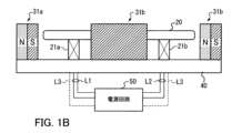
- FIG. 1B is a view of the reflector scanner 200 from the direction of the white arrow shown in FIG. 1A. It is a side view.
- the reflector scanner 200 is configured such that a mirror portion MR having a reflective surface swings in two axial directions around a first axis J1 and a second axis J2 orthogonal to the first axis J1, respectively.
- a mirror portion MR having a reflective surface swings in two axial directions around a first axis J1 and a second axis J2 orthogonal to the first axis J1, respectively.
- a MEMS Micro Electro Mechanical System
- reflector scanner 200 includes frame 20, posts 21a and 21b, a pair of magnets 31a and 31b as a first magnet, a pair of magnets 32a and 32b as a second magnet, and a base. It has a platform 40 .
- the frame 20 has a frame-shaped portion FR extending along the outer edge of one surface of the frame 20 and the openings Oa and the openings Oa, Os, and Ob juxtaposed along the direction of the first axis J1.
- a pair of bridging portions consisting of a bridging portion Ba between the portion Os and a bridging portion Bb between the opening Ob and the opening Os. That is, the frame 20 bridges the frame-shaped portion FR extending along the outer edge and the frame-shaped portions FR extending so as to sandwich the first axis J1 at portions facing each other across the second axis J2. , that is, a pair of connecting bridging portions (Ba, Bb).
- annular region Ra an annular region formed by the bridging portion closer to the magnet 31b among the pair of bridging portions described above and the frame-shaped portion FR around the opening Ob is referred to as an annular region Rb.
- a support 21a connected to the frame-shaped portion FR of the frame 20 via a torsion bar T2a extending along the first axis J1 is installed inside the opening Oa, that is, inside the annular region Ba.
- a support column is connected to the frame-shaped portion FR of the frame 20 via a torsion bar T2b as an elastic member extending along the first axis J1. 21b is installed.
- the torsion bars T1a, T1b, T2a and T2b are each made of an elastic member.
- a coil L1 wired in a loop or spiral is arranged in the annular portion of the annular region Ra.
- One end and the other end of the wiring forming the coil L1 are connected to the power supply circuit 50 via a pair of wirings wired inside the surface of the torsion bar T2a, the column 21a and the base 40, respectively.
- a coil L2 wired in a loop or spiral is arranged in the annular portion of the annular region Rb.
- One end and the other end of the wiring forming the coil L2 are connected to the power supply circuit 50 via a pair of wirings wired inside the surface of the torsion bar T2b, the column 21b and the base 40, respectively.
- a frame-shaped portion FR and a pair of bridging portions are provided so as to surround the mirror portion MR in a loop or spiral.
- Coils L3 (indicated by dashed lines) are arranged in the portions (Ba, Bb).
- One end of the wiring forming the coil L3 is connected to the power supply circuit 50 via wiring installed inside the frame-shaped portion FR, the surface of the torsion bar T2a, the support 21a, and the base 40.
- the other end of the wiring forming the coil L3 is connected to the power supply circuit 50 via wiring installed inside the frame-shaped portion FR, the surface of the torsion bar T2b, the support 21b, and the base 40.
- FIG. The pillars 21 a and 21 b are installed on the base 40 .
- As for the wiring on the pillars 21a and 21b it is possible to use TSVs (Through Silicon Via) as the pillars so that the wiring can be carried out inside the pillars. It may be led out outside by straddling over the frame 20 and the magnets (31a, 31b).
- the coil L1 is installed in the annular region Ra, and the coil L2 is installed in the annular region Rb. Further, a mirror portion MR and a third coil L3 are installed in the central region between the annular regions Ra and Rb, that is, in the region between the pair of bridging portions described above.
- the coil L3 includes a wiring section that is wired close to the magnet 32a or 32b so as to cross the region sandwiched by at least the pair of magnets 32a and 32b.
- the power supply circuit 50 supplies the coils L1 and L2 with first drive currents, which are alternating currents for swinging the mirror portion MR in the direction of rotation about the second axis J2. Further, the power supply circuit 50 supplies the coil L3 with a second drive current, which is an alternating current for swinging the mirror portion MR in the direction of rotation about the first axis J1.
- first drive currents which are alternating currents for swinging the mirror portion MR in the direction of rotation about the second axis J2.
- the power supply circuit 50 supplies the coil L3 with a second drive current, which is an alternating current for swinging the mirror portion MR in the direction of rotation about the first axis J1.
- the power supply circuit 50 is installed at a position separated from the base 40 in FIG. 1B, it may be installed directly on the base 40 .
- the magnets 31 a , 31 b , 32 a and 32 b are installed on the base 40 so as to be arranged one by one at positions on the outer circumference close to each side of the frame 20 .
- the height of each of the magnets 31 a , 31 b , 32 a and 32 b from the surface of the base 40 is equal to or greater than the height from the base 40 to the surface of the frame 20 .
- the magnets 31a and 31b as the first magnet pair are installed on the base 40 so as to sandwich the frame 20 with the surfaces of opposite polarities facing each other on the first axis J1.
- the magnets 32a and 32b as a second magnet pair are installed on the base 40 so as to sandwich the frame 20 with the surfaces of opposite polarities facing each other on the second axis J1.
- each of the magnets 32a and 32b in the direction along the direction of the first axis J1 is such that it can at least sandwich the central region, that is, the region between the pair of bridging portions (Ba, Bb). length.
- FIG. 2 is a top view of the reflector scanner 200 in which the direction of the current flowing through each coil of the reflector scanner 200, the direction of the magnetic field, and the direction of the Lorentz force are indicated by symbols or arrows at one point in time.
- the power supply circuit 50 supplies a drive current i1, which is an alternating current, to the coil L1, and supplies a drive current i1e, which is an alternating current obtained by inverting the phase of the drive current i1, to the coil L2.
- a drive current i1 flows through the coil L1 clockwise as shown by the arrow in FIG. 2
- the driving current i1e flows through the coil L2 clockwise as shown by the arrow in FIG. flow.
- the first Lorentz force is applied to the left end of the frame 20 according to the magnetic field B1 (indicated by the white arrow) by the magnet 31a and the drive current i1 (indicated by the black arrow) that traverses the magnetic field B1. Furthermore, a second Lorentz force is applied to the right end of the frame 20 in accordance with the magnetic field B1e (indicated by the white arrow) by the magnet 31b and the driving current i1e (indicated by the black arrow) across the magnetic field B1e. At this time, the direction in which the first Lorentz force is applied and the direction in which the second Lorentz force is applied are opposite to each other. , the other hangs in the direction in which the back surface of the frame 20 faces.
- the direction of the drive current flowing through the bridging portion Ba (Bb) of the coil L1 (L2) is opposite to the direction of the drive current flowing through the frame portion FR on the left (right) end side of the frame 20 . Therefore, the Lorentz force acting on the bridging portion Ba (Bb) due to the magnetic field B1 (B1e) shown in FIG. direction to hinder
- the distance from the bridging portion Ba (Bb) to the magnet 31a (31b) is longer than the distance from the frame portion FR at the left (right) end of the frame 20 to the magnet 31a (31b).
- the magnetic field b1 (b1e) at the bridging portion Ba (Bb) generated by the magnet 31a (31b) is smaller than the magnetic field B1 (B1e), so the generated torque is also small, and the effect of impeding the rotation of the frame 20 is small.
- the power supply circuit 50 supplies the drive current i2, which is an alternating current, to the coil L3.
- the drive current i2 flows through the coil L3 in the direction indicated by the arrow in FIG.
- the frame-shaped portion FR at the upper end of the frame 20 has a third Lorentzian current. It takes force. Further, a fourth Lorentz It takes force. At this time, the direction in which the third Lorentz force is applied and the direction in which the fourth Lorentz force is applied are opposite to each other. , the other hangs in the direction in which the back surface of the frame 20 faces. As a result, a force (couple of force) is applied to the frame 20 to rotate the frame 20 about the first axis J1. Furthermore, since the drive current i2 is an alternating current, the directions of the Lorentz force acting on the upper end and the lower end of the frame 20 are reversed at a period corresponding to the frequency of the alternating current while maintaining the opposite directions. .
- the frame 20 is also positioned at the bridging portion Ba (Bb).
- a couple of forces that rotate around the two axes J2 act as crosstalk.
- the distance from the bridging portion Ba (Bb) to the magnet 31a (31b) is longer than the distance from the left (right) end of the frame 20 to the magnet 31a (31b).
- the generated torque applied to the bridging portion Ba (Bb) is small, and the influence of crosstalk is also small.
- the frame 20 is provided with one set of bridging portions (Ba, Bb), but the number of bridging portions provided on the frame 20 is not limited to two. That is, as long as the frame 20 has a pair of bridging portions (Ba, Bb) surrounding the mirror portion MR, the number of bridging portions may be three or more.
- the reflector scanner 200 employs a configuration including the following frame, mirror section, and first and second drive sections to swing the mirror section in two axial directions.
- the frame (20) has a frame-like portion (FR) extending along one plane and is held rotatably about a first axis (J1) along the one plane. ing.
- the frame extends inside itself so as to sandwich the first axis, and a pair of bridging parts ( Ba, Bb).
- the mirror portion (MR) is connected to the inside of the frame via first elastic members (T1a, T1b) extending along a second axis along said one plane.
- the first driving units (31a, 31b, L1, L2) rotate the frame in the direction of rotation about the second axis
- the second driving units (32a, 32b, L3) rotate the frame. is rotated in the direction of rotation about the first axis.
- the first drive unit includes a first pair of magnets (31a, 31b) arranged to face each other on the first axis so as to sandwich the frame, and first and second magnet pairs wired to the frame. and a coil of The first coil (L1) includes one bridging portion (Ba) closer to one magnet (31a) of the first magnet pair (31a, 31b) than the mirror portion, and a frame-shaped portion (FR). is wired to a first annular portion (Ra) formed by the portion on one side of the first magnet pair from the one bridging portion.
- the second coil (L2) includes another bridging portion (Bb) closer to the other magnet (31b) of the first magnet pair (31a, 31b) than the mirror portion, and a frame-like portion (FR). is wired to a second annular portion (Bb) formed by the portion on the other side of the first magnet pair than the other bridging portion.
- the driving currents (i1, i1e) flowing through the first and second coils to rotate the frame in the direction of rotation about the second axis are It is possible to oscillate the mirror section in two axial directions while suppressing crosstalk that affects the force for rotating the frame in the direction of rotation about the first axis.
- FIG. 3A is a top plan view of a reflector scanner 300 according to a second embodiment of the present invention
- FIG. 3B is a view of the reflector scanner 300 from the direction of the hollow arrow shown in FIG. 3A. It is a side view.
- the magnet 31b is arranged such that the polarity of the surface of the magnet 31b facing the magnet 31a (for example, S pole) is opposite to the polarity of the magnet 31b of the reflector scanner 200 (for example, N pole). It is installed on the base 40 . That is, in the reflector scanner 300, the magnets 31a and 31b as the first pair of magnets are installed on the base 40 so that the facing surfaces thereof have the same polarity.
- the reflector scanner 300 employs a power supply circuit 50A in place of the power supply circuit 50 included in the reflector scanner 200. Since the configuration other than the above points is the same as that of the reflector scanner 200, the description of the other configuration is omitted.
- FIG. 4 is a top view of the reflector scanner 300 in which the direction of the current flowing through each coil of the reflector scanner 300, the direction of the magnetic field, and the direction of the Lorentz force are indicated by symbols or arrows at one point in time.
- the power supply circuit 50A supplies the drive current i2, which is an alternating current, to the coil L3. Furthermore, the power supply circuit 50A supplies a drive current i1, which is an alternating current, to the coil L1, and supplies a drive current i1e, which is an alternating current having the same phase as the drive current i1, to the coil L2.
- the drive current i1 flows through the coil L1 in the clockwise direction as shown by the arrow in FIG. 4
- the drive current i1e flows through the coil L2 in the counterclockwise direction as shown by the arrow in FIG. flow to
- the frame-shaped portion FR at the left end of the frame 20 has the first Lorentz force is applied.
- the frame-shaped portion FR at the right end of the frame 20 has a second Lorentz force is applied.
- the direction in which the first Lorentz force is applied and the direction in which the second Lorentz force is applied are opposite to each other.
- the other hangs in the direction in which the back surface of the frame 20 faces.
- a force (couple of forces) is applied to the frame 20 to rotate the frame 20 about the second axis J2.
- the drive currents i1 and i1e are alternating currents, the directions of the Lorentz force acting on the right end and the left end of the frame 20 are kept opposite to each other, and are applied in cycles corresponding to the frequency of the alternating current.
- the mirror portion MR can be swung in the direction of rotation about the second axis J2.
- the drive current i2 flowing through the coil L3 does not affect the rotation of the frame 20 about the second axis J2, that is, crosstalk does not occur.
- FIG. 5 is a top view of a reflector scanner 400 according to a third embodiment of the invention, viewed from above.
- magnets 32aX and 32bX are used instead of magnets 32a and 32b of reflector scanner 300 shown in FIG. 3A, and coil L3A is used instead of coil L3. , are identical to reflector scanner 300 .
- the coil L3A is looped or spirally formed on the surface of the frame 20 so as to surround the area where the mirror portion MR and the coils L1 and L2 are arranged. Wired in the frame.
- One end of the wiring forming the coil L3A is connected to the power supply circuit 50A via wiring installed inside each of the surface of the torsion bar T2a, the support 21a and the base 40.
- FIG. The other end of the wiring forming the coil L3A is connected to the power supply circuit 50A via wiring installed inside each of the surface of the torsion bar T2b, the support 21b, and the base 40. As shown in FIG.
- the magnets 32aX and 32bX are arranged outside the frame 20 so as to sandwich the wiring section of the wiring of the coil L3A that is laid along the direction of the first axis J1.
- the magnets 32aX and 32bX as the second magnet pair are longer in the direction along the direction of the first axis J1 than the magnets 32a and 32b shown in FIG. 3A. .
- the driving current i2 does not affect the rotational operation of the frame 20 about the second axis J2, that is, crosstalk does not occur. Further, on the surface of the frame 20, the direction of the Lorentz force generated in the region between the annular region Ra and the magnet 32aX (32bX) according to the drive current i1 (i1e) is This is opposite to the direction of the Lorentz force generated in the region of .
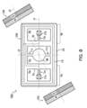
- FIG. 6A is a top view of a reflector scanner 500 according to a fourth embodiment of the present invention viewed from above, and FIG. 6B is a view of the reflector scanner 500 from the direction of the white arrow shown in FIG. 6A. It is a side view.
- the coils L1 and L2 are connected in parallel, the coil L3B is used instead of the coil L3, and the power supply circuit 50B is used instead of the power supply circuit 50.
- the configuration is the same as the reflector scanner 200 shown in FIGS. 1A and 1B.
- Region Rb includes coil L2, strut 21b and torsion bar T2b. Furthermore, a central region between these annular regions Ra and Rb includes a mirror portion MR, torsion bars T1a and T1b, and a coil L3B.
- one end and the other end of the wiring forming the coil L1 are connected to the power supply circuit 50B via a pair of wiring wired inside each of the surface of the torsion bar T2a, the column 21a and the base 40.
- One end and the other end of the wiring forming the coil L2 are connected in parallel to the coil L1.
- the coil L3B is wired in a loop or spiral to the pair of bridging portions Ba and Bb and the frame portion FR so as to surround the mirror portion MR.
- one end and the other end of the wiring forming the coil L3B are connected via a pair of wirings installed inside each of the frame-shaped portion FR on the outer periphery of the opening Ob, the surface of the torsion bar T2b, the support 21b, and the base 40. , and the power supply circuit 50B.
- the power supply circuit 50B supplies a drive current i1 as an alternating current to the coil L1, and supplies a drive current i2 as an alternating current to the coil L3B.
- the number of wires to be wired on the surfaces of the torsion bars T2a and T2b can be reduced from three to two. It is possible to reduce the width. Furthermore, according to the configuration shown in FIGS. 6A and 6B, the number of wires of the coil L3B that crosses the magnetic field of the magnet 32a in the section close to the magnet 32a and the number of wires that cross the magnetic field of the magnet 32b in the section close to the magnet 32b It is possible to match the number of wires of the coil L3B. As a result, it is possible to achieve a torque balance of the Lorentz force that promotes clockwise rotation and counterclockwise rotation about the first axis J1.
- FIG. 7 is a top view of a reflector scanner 600 according to a fifth embodiment of the present invention, viewed from above.
- the post 21a is connected to the bridging portion Ba of the pair of bridging portions (Ba, Bb) through the torsion bar T2a extending along the first axis J1.
- the strut 21b is connected to the bridging portion Bb of the pair of bridging portions (Ba, Bb) via a torsion bar T2b extending along the first axis J1.
- the configuration other than the points described above is the same as that of the reflector scanner 300 shown in FIGS. 3A and 3B.
- the torsion bar T2a (T2b) and the frame 20 are connected to the frame-shaped portion FR of the frame 20, for example, as shown in FIG. 3A. is closer to the second axis J2.
- the amount of displacement associated with bending of the torsion bar T2a (T2b) during rotation of the frame 20 about the second axis J2 is reduced. Therefore, the tensile stress applied to the torsion bar T2a (T2b) and the wiring on the surface thereof is reduced, the life of the torsion bar T2a (T2b) is extended by that amount, and the wiring is broken at the torsion bar T2a (T2b). Since the probability is low, it is possible to extend the life of the reflector scanner itself.
- the frame 20 is rotated around the second axis J2 by the first drive currents (i1, i1e) passed through the coils L1 and L2, and the second drive current passed through the coil L3.
- the frame 20 is rotated around the first axis J1.
- FIG. 8 is a top view of a reflector scanner 700 as a modified example of the reflector scanner 600 shown in FIG. 7, as seen from above.
- the coil LQ made of a single wire is helically arranged in each of the annular regions Ra and Rb of the frame 20A and the central region including the bridging portions Ba and Bb. Or wired in a loop.
- one end of the wiring forming the coil LQ is led out to the outside through a single wiring wired inside or on the surface of the torsion bar T2a, the support 21a and the base 40, respectively.
- the other end of the wiring forming the coil LQ is led out through a single wiring wired inside or on the surface of the torsion bar T2b, the support 21b, and the base 40 respectively.
- a pair of magnets 33a and 33b are positioned on frame 20A on a third axis J3 extending diagonally of frame 20A. are arranged facing each other so as to sandwich the
- the power supply circuit generates a drive current obtained by superimposing the drive currents i1, i1e and i2 described above, and supplies the drive current to one end and the other end of the wiring forming the coil LQ. , J2) as the central axis.
Landscapes
- Physics & Mathematics (AREA)
- General Physics & Mathematics (AREA)
- Optics & Photonics (AREA)
- Engineering & Computer Science (AREA)
- Electromagnetism (AREA)
- Power Engineering (AREA)
- Mechanical Engineering (AREA)
- Mechanical Light Control Or Optical Switches (AREA)
- Mechanical Optical Scanning Systems (AREA)
- Micromachines (AREA)
- Reciprocating, Oscillating Or Vibrating Motors (AREA)
Priority Applications (7)
| Application Number | Priority Date | Filing Date | Title |
|---|---|---|---|
| PCT/JP2021/037356 WO2023058226A1 (ja) | 2021-10-08 | 2021-10-08 | 反射体スキャナ |
| CN202180102156.9A CN117999132A (zh) | 2021-10-08 | 2021-10-08 | 反射体扫描器 |
| JP2023552658A JP7638560B2 (ja) | 2021-10-08 | 2021-10-08 | 反射体スキャナ |
| EP21959967.7A EP4382215A4 (en) | 2021-10-08 | 2021-10-08 | REFLECTIVE SCANNER |
| US18/682,056 US12601907B2 (en) | 2021-10-08 | 2021-10-08 | Reflector scanner |
| KR1020247008128A KR102941778B1 (ko) | 2021-10-08 | 2021-10-08 | 반사체 스캐너 |
| JP2025020657A JP7853732B2 (ja) | 2021-10-08 | 2025-02-12 | 反射体スキャナ |
Applications Claiming Priority (1)
| Application Number | Priority Date | Filing Date | Title |
|---|---|---|---|
| PCT/JP2021/037356 WO2023058226A1 (ja) | 2021-10-08 | 2021-10-08 | 反射体スキャナ |
Publications (1)
| Publication Number | Publication Date |
|---|---|
| WO2023058226A1 true WO2023058226A1 (ja) | 2023-04-13 |
Family
ID=85804067
Family Applications (1)
| Application Number | Title | Priority Date | Filing Date |
|---|---|---|---|
| PCT/JP2021/037356 Ceased WO2023058226A1 (ja) | 2021-10-08 | 2021-10-08 | 反射体スキャナ |
Country Status (6)
| Country | Link |
|---|---|
| US (1) | US12601907B2 (https=) |
| EP (1) | EP4382215A4 (https=) |
| JP (2) | JP7638560B2 (https=) |
| KR (1) | KR102941778B1 (https=) |
| CN (1) | CN117999132A (https=) |
| WO (1) | WO2023058226A1 (https=) |
Cited By (1)
| Publication number | Priority date | Publication date | Assignee | Title |
|---|---|---|---|---|
| JP2025076486A (ja) * | 2021-10-08 | 2025-05-15 | Yitoaマイクロテクノロジー株式会社 | 反射体スキャナ |
Citations (2)
| Publication number | Priority date | Publication date | Assignee | Title |
|---|---|---|---|---|
| JP2004354283A (ja) * | 2003-05-30 | 2004-12-16 | Miyota Kk | 表面検査用画像装置の照明ユニットとその制御方法。 |
| JP6726356B2 (ja) | 2017-03-13 | 2020-07-22 | パイオニア株式会社 | 駆動装置および距離測定装置 |
Family Cites Families (15)
| Publication number | Priority date | Publication date | Assignee | Title |
|---|---|---|---|---|
| JPH0672635A (ja) | 1992-08-28 | 1994-03-15 | Teijin Ltd | 自動玉揚方法 |
| US6859325B2 (en) * | 2001-06-20 | 2005-02-22 | Sony Corporation | Objective lens device, optical pickup device, and optical information recording and/or reproduction device |
| JP4164421B2 (ja) * | 2002-08-26 | 2008-10-15 | キヤノン株式会社 | 揺動装置、揺動装置を用いた光偏向器、及び光偏向器を用いた画像表示装置、画像形成装置、並びにその製法 |
| US6924915B2 (en) * | 2002-08-26 | 2005-08-02 | Canon Kabushiki Kaisha | Oscillation device, optical deflector using the oscillation device, and image display device and image forming apparatus using the optical deflector, and method of manufacturing the oscillation device |
| JP2005165276A (ja) * | 2003-11-10 | 2005-06-23 | Olympus Corp | 光偏向器 |
| KR100908120B1 (ko) * | 2006-11-01 | 2009-07-16 | 삼성전기주식회사 | 전자기 마이크로 액츄에이터 |
| JP5007648B2 (ja) * | 2007-10-12 | 2012-08-22 | セイコーエプソン株式会社 | アクチュエータ、光スキャナおよび画像形成装置 |
| JP2010107666A (ja) * | 2008-10-29 | 2010-05-13 | Osaka Univ | 光スキャナ |
| DE102010064218A1 (de) * | 2010-12-27 | 2012-06-28 | Robert Bosch Gmbh | Magnetisch antreibbarer Mikrospiegel |
| WO2013168273A1 (ja) * | 2012-05-10 | 2013-11-14 | パイオニア株式会社 | 駆動装置 |
| JP6075062B2 (ja) * | 2012-12-27 | 2017-02-08 | セイコーエプソン株式会社 | アクチュエーター、光スキャナーおよび画像形成装置 |
| KR101894375B1 (ko) * | 2016-07-13 | 2018-09-04 | 이화여자대학교 산학협력단 | 스캐닝 마이크로 미러 |
| JP2018081155A (ja) * | 2016-11-14 | 2018-05-24 | 純 鈴木 | 駆動装置 |
| JP2020027044A (ja) * | 2018-08-13 | 2020-02-20 | パイオニア株式会社 | 走査装置、走査装置の制御方法、プログラム及び記録媒体並びに測距装置 |
| US12601907B2 (en) | 2021-10-08 | 2026-04-14 | Yitoa Micro Technology Corporation | Reflector scanner |
-
2021
- 2021-10-08 US US18/682,056 patent/US12601907B2/en active Active
- 2021-10-08 KR KR1020247008128A patent/KR102941778B1/ko active Active
- 2021-10-08 JP JP2023552658A patent/JP7638560B2/ja active Active
- 2021-10-08 CN CN202180102156.9A patent/CN117999132A/zh active Pending
- 2021-10-08 EP EP21959967.7A patent/EP4382215A4/en active Pending
- 2021-10-08 WO PCT/JP2021/037356 patent/WO2023058226A1/ja not_active Ceased
-
2025
- 2025-02-12 JP JP2025020657A patent/JP7853732B2/ja active Active
Patent Citations (2)
| Publication number | Priority date | Publication date | Assignee | Title |
|---|---|---|---|---|
| JP2004354283A (ja) * | 2003-05-30 | 2004-12-16 | Miyota Kk | 表面検査用画像装置の照明ユニットとその制御方法。 |
| JP6726356B2 (ja) | 2017-03-13 | 2020-07-22 | パイオニア株式会社 | 駆動装置および距離測定装置 |
Non-Patent Citations (1)
| Title |
|---|
| See also references of EP4382215A4 |
Cited By (3)
| Publication number | Priority date | Publication date | Assignee | Title |
|---|---|---|---|---|
| JP2025076486A (ja) * | 2021-10-08 | 2025-05-15 | Yitoaマイクロテクノロジー株式会社 | 反射体スキャナ |
| US12601907B2 (en) | 2021-10-08 | 2026-04-14 | Yitoa Micro Technology Corporation | Reflector scanner |
| JP7853732B2 (ja) | 2021-10-08 | 2026-04-30 | Yitoaマイクロテクノロジー株式会社 | 反射体スキャナ |
Also Published As
| Publication number | Publication date |
|---|---|
| JP2025076486A (ja) | 2025-05-15 |
| JPWO2023058226A1 (https=) | 2023-04-13 |
| US20240353675A1 (en) | 2024-10-24 |
| EP4382215A4 (en) | 2025-05-28 |
| JP7638560B2 (ja) | 2025-03-04 |
| KR102941778B1 (ko) | 2026-03-19 |
| CN117999132A (zh) | 2024-05-07 |
| US12601907B2 (en) | 2026-04-14 |
| KR20240046229A (ko) | 2024-04-08 |
| JP7853732B2 (ja) | 2026-04-30 |
| EP4382215A1 (en) | 2024-06-12 |
Similar Documents
| Publication | Publication Date | Title |
|---|---|---|
| JP4928301B2 (ja) | 揺動体装置、その駆動方法、光偏向器、及び光偏向器を用いた画像表示装置 | |
| JP4827993B2 (ja) | 駆動装置 | |
| JP5860066B2 (ja) | アクチュエータ | |
| JP7853732B2 (ja) | 反射体スキャナ | |
| JP2005173411A (ja) | 光偏向器 | |
| KR20090031104A (ko) | 2축 구동 전자기 스캐너 | |
| KR102233438B1 (ko) | 자기부상형 스테이지 | |
| KR100941798B1 (ko) | 스캐닝 마이크로미러 | |
| JP2021033087A (ja) | ミラースキャナ | |
| JP2003195204A (ja) | 光偏向器及び光偏向器アレイ | |
| JP2016095519A (ja) | アクチュエータ | |
| JP4475421B2 (ja) | マイクロミラー、及び、マイクロミラーデバイス | |
| JP2004237400A (ja) | プレーナー型アクチュエータ | |
| JPWO2023058226A5 (https=) | ||
| JP2006072251A (ja) | プレーナ型アクチュエータ | |
| JP2019056935A (ja) | アクチュエータ | |
| JP2010172190A (ja) | プレーナ型電磁アクチュエータ | |
| WO2013168273A1 (ja) | 駆動装置 | |
| WO2013076844A1 (ja) | アクチュエータ | |
| KR100789574B1 (ko) | 스캐닝 마이크로미러 | |
| JP4963864B2 (ja) | 電磁アクチュエータ | |
| JP7516651B2 (ja) | アクチュエーター | |
| JP7044498B2 (ja) | アクチュエータ | |
| KR20080067064A (ko) | 스캐닝 마이크로미러 | |
| JP7340540B2 (ja) | 駆動装置 |
Legal Events
| Date | Code | Title | Description |
|---|---|---|---|
| 121 | Ep: the epo has been informed by wipo that ep was designated in this application |
Ref document number: 21959967 Country of ref document: EP Kind code of ref document: A1 |
|
| WWE | Wipo information: entry into national phase |
Ref document number: 2023552658 Country of ref document: JP |
|
| WWE | Wipo information: entry into national phase |
Ref document number: 18682056 Country of ref document: US |
|
| WWE | Wipo information: entry into national phase |
Ref document number: 202180102156.9 Country of ref document: CN |
|
| ENP | Entry into the national phase |
Ref document number: 20247008128 Country of ref document: KR Kind code of ref document: A |
|
| ENP | Entry into the national phase |
Ref document number: 2021959967 Country of ref document: EP Effective date: 20240308 |
|
| NENP | Non-entry into the national phase |
Ref country code: DE |
|
| WWG | Wipo information: grant in national office |
Ref document number: 18682056 Country of ref document: US |