WO2023047508A1 - 除菌・ウイルス不活化装置、これを搭載した空気調和機および除菌・ウイルス不活化方法 - Google Patents
除菌・ウイルス不活化装置、これを搭載した空気調和機および除菌・ウイルス不活化方法 Download PDFInfo
- Publication number
- WO2023047508A1 WO2023047508A1 PCT/JP2021/034958 JP2021034958W WO2023047508A1 WO 2023047508 A1 WO2023047508 A1 WO 2023047508A1 JP 2021034958 W JP2021034958 W JP 2021034958W WO 2023047508 A1 WO2023047508 A1 WO 2023047508A1
- Authority
- WO
- WIPO (PCT)
- Prior art keywords
- sterilization
- virus inactivation
- unit
- substance
- target space
- Prior art date
- Legal status (The legal status is an assumption and is not a legal conclusion. Google has not performed a legal analysis and makes no representation as to the accuracy of the status listed.)
- Ceased
Links
Images





Classifications
-
- A—HUMAN NECESSITIES
- A61—MEDICAL OR VETERINARY SCIENCE; HYGIENE
- A61L—METHODS OR APPARATUS FOR STERILISING MATERIALS OR OBJECTS IN GENERAL; DISINFECTION, STERILISATION OR DEODORISATION OF AIR; CHEMICAL ASPECTS OF BANDAGES, DRESSINGS, ABSORBENT PADS OR SURGICAL ARTICLES; MATERIALS FOR BANDAGES, DRESSINGS, ABSORBENT PADS OR SURGICAL ARTICLES
- A61L9/00—Disinfection, sterilisation or deodorisation of air
- A61L9/015—Disinfection, sterilisation or deodorisation of air using gaseous or vaporous substances, e.g. ozone
- A61L9/04—Disinfection, sterilisation or deodorisation of air using gaseous or vaporous substances, e.g. ozone using substances evaporated in the air without heating
- A61L9/12—Apparatus, e.g. holders, therefor
- A61L9/122—Apparatus, e.g. holders, therefor comprising a fan
-
- A—HUMAN NECESSITIES
- A61—MEDICAL OR VETERINARY SCIENCE; HYGIENE
- A61L—METHODS OR APPARATUS FOR STERILISING MATERIALS OR OBJECTS IN GENERAL; DISINFECTION, STERILISATION OR DEODORISATION OF AIR; CHEMICAL ASPECTS OF BANDAGES, DRESSINGS, ABSORBENT PADS OR SURGICAL ARTICLES; MATERIALS FOR BANDAGES, DRESSINGS, ABSORBENT PADS OR SURGICAL ARTICLES
- A61L9/00—Disinfection, sterilisation or deodorisation of air
- A61L9/14—Disinfection, sterilisation or deodorisation of air using sprayed or atomised substances including air-liquid contact processes
-
- A—HUMAN NECESSITIES
- A61—MEDICAL OR VETERINARY SCIENCE; HYGIENE
- A61L—METHODS OR APPARATUS FOR STERILISING MATERIALS OR OBJECTS IN GENERAL; DISINFECTION, STERILISATION OR DEODORISATION OF AIR; CHEMICAL ASPECTS OF BANDAGES, DRESSINGS, ABSORBENT PADS OR SURGICAL ARTICLES; MATERIALS FOR BANDAGES, DRESSINGS, ABSORBENT PADS OR SURGICAL ARTICLES
- A61L2/00—Disinfection or sterilisation of materials or objects, in general; Accessories therefor
- A61L2/16—Disinfection or sterilisation of materials or objects, in general; Accessories therefor using chemical substances
- A61L2/20—Gaseous substances, e.g. vapours
-
- A—HUMAN NECESSITIES
- A61—MEDICAL OR VETERINARY SCIENCE; HYGIENE
- A61L—METHODS OR APPARATUS FOR STERILISING MATERIALS OR OBJECTS IN GENERAL; DISINFECTION, STERILISATION OR DEODORISATION OF AIR; CHEMICAL ASPECTS OF BANDAGES, DRESSINGS, ABSORBENT PADS OR SURGICAL ARTICLES; MATERIALS FOR BANDAGES, DRESSINGS, ABSORBENT PADS OR SURGICAL ARTICLES
- A61L2/00—Disinfection or sterilisation of materials or objects, in general; Accessories therefor
- A61L2/24—Apparatus using programmed or automatic operation
-
- F—MECHANICAL ENGINEERING; LIGHTING; HEATING; WEAPONS; BLASTING
- F24—HEATING; RANGES; VENTILATING
- F24F—AIR-CONDITIONING; AIR-HUMIDIFICATION; VENTILATION; USE OF AIR CURRENTS FOR SCREENING
- F24F1/00—Room units for air-conditioning, e.g. separate or self-contained units or units receiving primary air from a central station
- F24F1/0007—Indoor units, e.g. fan coil units
- F24F1/0071—Indoor units, e.g. fan coil units with means for purifying supplied air
-
- F—MECHANICAL ENGINEERING; LIGHTING; HEATING; WEAPONS; BLASTING
- F24—HEATING; RANGES; VENTILATING
- F24F—AIR-CONDITIONING; AIR-HUMIDIFICATION; VENTILATION; USE OF AIR CURRENTS FOR SCREENING
- F24F11/00—Control or safety arrangements
- F24F11/70—Control systems characterised by their outputs; Constructional details thereof
- F24F11/72—Control systems characterised by their outputs; Constructional details thereof for controlling the supply of treated air, e.g. its pressure
- F24F11/74—Control systems characterised by their outputs; Constructional details thereof for controlling the supply of treated air, e.g. its pressure for controlling air flow rate or air velocity
-
- F—MECHANICAL ENGINEERING; LIGHTING; HEATING; WEAPONS; BLASTING
- F24—HEATING; RANGES; VENTILATING
- F24F—AIR-CONDITIONING; AIR-HUMIDIFICATION; VENTILATION; USE OF AIR CURRENTS FOR SCREENING
- F24F8/00—Treatment, e.g. purification, of air supplied to human living or working spaces otherwise than by heating, cooling, humidifying or drying
- F24F8/20—Treatment, e.g. purification, of air supplied to human living or working spaces otherwise than by heating, cooling, humidifying or drying by sterilisation
-
- F—MECHANICAL ENGINEERING; LIGHTING; HEATING; WEAPONS; BLASTING
- F24—HEATING; RANGES; VENTILATING
- F24F—AIR-CONDITIONING; AIR-HUMIDIFICATION; VENTILATION; USE OF AIR CURRENTS FOR SCREENING
- F24F8/00—Treatment, e.g. purification, of air supplied to human living or working spaces otherwise than by heating, cooling, humidifying or drying
- F24F8/20—Treatment, e.g. purification, of air supplied to human living or working spaces otherwise than by heating, cooling, humidifying or drying by sterilisation
- F24F8/24—Treatment, e.g. purification, of air supplied to human living or working spaces otherwise than by heating, cooling, humidifying or drying by sterilisation using sterilising media
-
- F—MECHANICAL ENGINEERING; LIGHTING; HEATING; WEAPONS; BLASTING
- F24—HEATING; RANGES; VENTILATING
- F24F—AIR-CONDITIONING; AIR-HUMIDIFICATION; VENTILATION; USE OF AIR CURRENTS FOR SCREENING
- F24F8/00—Treatment, e.g. purification, of air supplied to human living or working spaces otherwise than by heating, cooling, humidifying or drying
- F24F8/80—Self-contained air purifiers
-
- A—HUMAN NECESSITIES
- A61—MEDICAL OR VETERINARY SCIENCE; HYGIENE
- A61L—METHODS OR APPARATUS FOR STERILISING MATERIALS OR OBJECTS IN GENERAL; DISINFECTION, STERILISATION OR DEODORISATION OF AIR; CHEMICAL ASPECTS OF BANDAGES, DRESSINGS, ABSORBENT PADS OR SURGICAL ARTICLES; MATERIALS FOR BANDAGES, DRESSINGS, ABSORBENT PADS OR SURGICAL ARTICLES
- A61L2103/00—Materials or objects being the target of disinfection or sterilisation
- A61L2103/75—Room floors or walls
-
- A—HUMAN NECESSITIES
- A61—MEDICAL OR VETERINARY SCIENCE; HYGIENE
- A61L—METHODS OR APPARATUS FOR STERILISING MATERIALS OR OBJECTS IN GENERAL; DISINFECTION, STERILISATION OR DEODORISATION OF AIR; CHEMICAL ASPECTS OF BANDAGES, DRESSINGS, ABSORBENT PADS OR SURGICAL ARTICLES; MATERIALS FOR BANDAGES, DRESSINGS, ABSORBENT PADS OR SURGICAL ARTICLES
- A61L2202/00—Aspects relating to methods or apparatus for disinfecting or sterilising materials or objects
- A61L2202/10—Apparatus features
- A61L2202/14—Means for controlling sterilisation processes, data processing, presentation and storage means, e.g. sensors, controllers, programs
-
- A—HUMAN NECESSITIES
- A61—MEDICAL OR VETERINARY SCIENCE; HYGIENE
- A61L—METHODS OR APPARATUS FOR STERILISING MATERIALS OR OBJECTS IN GENERAL; DISINFECTION, STERILISATION OR DEODORISATION OF AIR; CHEMICAL ASPECTS OF BANDAGES, DRESSINGS, ABSORBENT PADS OR SURGICAL ARTICLES; MATERIALS FOR BANDAGES, DRESSINGS, ABSORBENT PADS OR SURGICAL ARTICLES
- A61L2202/00—Aspects relating to methods or apparatus for disinfecting or sterilising materials or objects
- A61L2202/10—Apparatus features
- A61L2202/15—Biocide distribution means, e.g. nozzles, pumps, manifolds, fans, baffles, sprayers
-
- A—HUMAN NECESSITIES
- A61—MEDICAL OR VETERINARY SCIENCE; HYGIENE
- A61L—METHODS OR APPARATUS FOR STERILISING MATERIALS OR OBJECTS IN GENERAL; DISINFECTION, STERILISATION OR DEODORISATION OF AIR; CHEMICAL ASPECTS OF BANDAGES, DRESSINGS, ABSORBENT PADS OR SURGICAL ARTICLES; MATERIALS FOR BANDAGES, DRESSINGS, ABSORBENT PADS OR SURGICAL ARTICLES
- A61L2209/00—Aspects relating to disinfection, sterilisation or deodorisation of air
- A61L2209/10—Apparatus features
- A61L2209/11—Apparatus for controlling air treatment
- A61L2209/111—Sensor means, e.g. motion, brightness, scent, contaminant sensors
-
- A—HUMAN NECESSITIES
- A61—MEDICAL OR VETERINARY SCIENCE; HYGIENE
- A61L—METHODS OR APPARATUS FOR STERILISING MATERIALS OR OBJECTS IN GENERAL; DISINFECTION, STERILISATION OR DEODORISATION OF AIR; CHEMICAL ASPECTS OF BANDAGES, DRESSINGS, ABSORBENT PADS OR SURGICAL ARTICLES; MATERIALS FOR BANDAGES, DRESSINGS, ABSORBENT PADS OR SURGICAL ARTICLES
- A61L2209/00—Aspects relating to disinfection, sterilisation or deodorisation of air
- A61L2209/10—Apparatus features
- A61L2209/13—Dispensing or storing means for active compounds
- A61L2209/134—Distributing means, e.g. baffles, valves, manifolds, nozzles
-
- A—HUMAN NECESSITIES
- A61—MEDICAL OR VETERINARY SCIENCE; HYGIENE
- A61L—METHODS OR APPARATUS FOR STERILISING MATERIALS OR OBJECTS IN GENERAL; DISINFECTION, STERILISATION OR DEODORISATION OF AIR; CHEMICAL ASPECTS OF BANDAGES, DRESSINGS, ABSORBENT PADS OR SURGICAL ARTICLES; MATERIALS FOR BANDAGES, DRESSINGS, ABSORBENT PADS OR SURGICAL ARTICLES
- A61L2209/00—Aspects relating to disinfection, sterilisation or deodorisation of air
- A61L2209/10—Apparatus features
- A61L2209/16—Connections to a HVAC unit
-
- F—MECHANICAL ENGINEERING; LIGHTING; HEATING; WEAPONS; BLASTING
- F24—HEATING; RANGES; VENTILATING
- F24F—AIR-CONDITIONING; AIR-HUMIDIFICATION; VENTILATION; USE OF AIR CURRENTS FOR SCREENING
- F24F11/00—Control or safety arrangements
- F24F11/70—Control systems characterised by their outputs; Constructional details thereof
- F24F11/72—Control systems characterised by their outputs; Constructional details thereof for controlling the supply of treated air, e.g. its pressure
- F24F11/79—Control systems characterised by their outputs; Constructional details thereof for controlling the supply of treated air, e.g. its pressure for controlling the direction of the supplied air
-
- F—MECHANICAL ENGINEERING; LIGHTING; HEATING; WEAPONS; BLASTING
- F24—HEATING; RANGES; VENTILATING
- F24F—AIR-CONDITIONING; AIR-HUMIDIFICATION; VENTILATION; USE OF AIR CURRENTS FOR SCREENING
- F24F2120/00—Control inputs relating to users or occupants
- F24F2120/10—Occupancy
- F24F2120/12—Position of occupants
-
- F—MECHANICAL ENGINEERING; LIGHTING; HEATING; WEAPONS; BLASTING
- F24—HEATING; RANGES; VENTILATING
- F24F—AIR-CONDITIONING; AIR-HUMIDIFICATION; VENTILATION; USE OF AIR CURRENTS FOR SCREENING
- F24F2120/00—Control inputs relating to users or occupants
- F24F2120/10—Occupancy
- F24F2120/14—Activity of occupants
-
- F—MECHANICAL ENGINEERING; LIGHTING; HEATING; WEAPONS; BLASTING
- F24—HEATING; RANGES; VENTILATING
- F24F—AIR-CONDITIONING; AIR-HUMIDIFICATION; VENTILATION; USE OF AIR CURRENTS FOR SCREENING
- F24F8/00—Treatment, e.g. purification, of air supplied to human living or working spaces otherwise than by heating, cooling, humidifying or drying
- F24F8/20—Treatment, e.g. purification, of air supplied to human living or working spaces otherwise than by heating, cooling, humidifying or drying by sterilisation
- F24F8/24—Treatment, e.g. purification, of air supplied to human living or working spaces otherwise than by heating, cooling, humidifying or drying by sterilisation using sterilising media
- F24F8/26—Treatment, e.g. purification, of air supplied to human living or working spaces otherwise than by heating, cooling, humidifying or drying by sterilisation using sterilising media using ozone
-
- Y—GENERAL TAGGING OF NEW TECHNOLOGICAL DEVELOPMENTS; GENERAL TAGGING OF CROSS-SECTIONAL TECHNOLOGIES SPANNING OVER SEVERAL SECTIONS OF THE IPC; TECHNICAL SUBJECTS COVERED BY FORMER USPC CROSS-REFERENCE ART COLLECTIONS [XRACs] AND DIGESTS
- Y02—TECHNOLOGIES OR APPLICATIONS FOR MITIGATION OR ADAPTATION AGAINST CLIMATE CHANGE
- Y02A—TECHNOLOGIES FOR ADAPTATION TO CLIMATE CHANGE
- Y02A50/00—TECHNOLOGIES FOR ADAPTATION TO CLIMATE CHANGE in human health protection, e.g. against extreme weather
- Y02A50/20—Air quality improvement or preservation, e.g. vehicle emission control or emission reduction by using catalytic converters
Definitions
- the present disclosure relates to a sterilization/virus inactivation device that sterilizes or inactivates viruses, an air conditioner equipped with the same, and a sterilization/virus inactivation method.
- ions, ozone gas, hypochlorous acid water, and chlorine dioxide exist as substances that can disinfect and inactivate bacteria, mold, viruses, etc.
- Ions or ozone gas are generated by electrical discharge.
- Hypochlorous acid water or chlorine dioxide is generated by electrolysis or chemical compounding. Bacteria floating in the indoor air can be sterilized and viruses can be inactivated by sending these specific substances indoors with a fan.
- Patent Document 1 proposes a technique for emitting ions generated by electric discharge to a predetermined area in a room to disinfect the area.
- the presence or absence of people in the room is monitored by a human sensor, normal sterilization operation is performed while there are people in the room, and sterilization performance is better than normal sterilization operation when there are no people in the room.
- Patent Document 1 the sterilization effect in the room is enhanced by performing sterilization operation with higher sterilization performance than normal sterilization operation when there are no people in the room.
- the locations where bacteria, molds, viruses, etc. actually exist in a room are not uniform within a given area, and variations are seen with the movement of moving objects such as people carrying microorganisms, including pathogenic microorganisms.
- part of the specific substance released into the predetermined area in the room is wasted, and there is a risk that the indoor disinfection or virus inactivation cannot be performed efficiently.
- the present disclosure has been made in view of such points, and is a sterilization/virus inactivation device capable of efficiently sterilizing or inactivating viruses in a target space, an air conditioner equipped with the same, and
- An object of the present invention is to provide a sterilization/virus inactivation method.
- the sterilization/virus inactivation device is a sterilization/virus inactivation device that performs sterilization processing or inactivation processing in a target space where a moving body enters and exits, and movement of a portion in contact with the moving body in the target space
- a trajectory detection unit that detects a trajectory
- a substance generation unit that generates a specific substance that performs sterilization processing or inactivation processing
- a transport unit that generates an air flow and transports the specific substance generated by the substance generation unit to the movement trajectory.
- An air conditioner includes the above-described sterilization/virus inactivation device and a heat exchanger that exchanges heat between a refrigerant flowing inside and air, and the air that has been temperature-controlled by passing through the heat exchanger A stream that transports an air stream containing a specific substance to a moving trajectory.
- the sterilization/virus deactivation method is a sterilization/virus deactivation method that performs sterilization or inactivation processing in a target space where a moving body enters and exits, and detects the movement trajectory of the moving body in the target space. It comprises a trajectory detection step, and a sterilization/inactivation step of generating an air flow from the transportation section and transporting the specific substance generated from the substance generation section to the movement trajectory.
- a sterilization/virus inactivation device capable of efficiently sterilizing bacteria or inactivating viruses in a target space, an air conditioner equipped with the same, and a sterilization/virus inactivation device can provide a method.
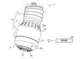
- FIG. 1 is an external view of a sterilization/virus inactivation device according to Embodiment 1.
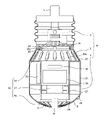
- FIG. 1 is a diagram showing an example of a schematic cross section of a sterilization/virus inactivation device according to Embodiment 1.
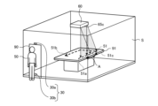
- FIG. 2 is a diagram showing a mode of use of the sterilization/virus inactivation device according to Embodiment 1; 2 is a perspective view showing a grill body of the sterilization/virus inactivation device according to Embodiment 1.
- FIG. 1 is a block diagram of a sterilization/virus inactivation device according to Embodiment 1.
- FIG. FIG. 4 is a diagram showing the relationship between ion concentration and sterilization/inactivation effect; FIG.
- FIG. 5 is an explanatory diagram of the trajectory detection operation of the sterilization/virus inactivation device according to Embodiment 1;
- FIG. 5 is an explanatory diagram of a modification of the control of the sterilization/virus inactivation device according to Embodiment 1;
- 2 is a block diagram of a sterilization/virus inactivation device according to Embodiment 2.
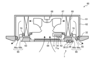
- FIG. FIG. 11 is a schematic cross-sectional view of an air conditioner according to Embodiment 3;
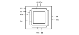
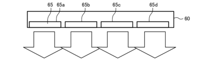
- FIG. 13 is a schematic diagram of the air conditioner 60 of FIG. 12 viewed from directly below;
- FIG. 13 is an explanatory diagram of the sterilization/inactivation operation by the air conditioner 60 of FIG. 12;
- FIG. 10 is a diagram showing an operation flowchart of an air conditioner according to Embodiment 3;
- FIG. 11 is a schematic diagram of a modified example of the air conditioner 60 according to Embodiment 3 as viewed from directly below.
- FIG. 17 is an explanatory diagram (part 1) of the sterilization/inactivation operation by the air conditioner 60 of FIG. 16;
- FIG. 17 is an explanatory diagram (part 2) of the sterilization/inactivation operation by the air conditioner 60 of FIG. 16;
- It is a schematic diagram of a modification of the air conditioner 60 according to Embodiment 3 as viewed from the side.
- FIG. 20 is an explanatory diagram of the sterilization/inactivation operation by the air conditioner 60 of FIG. 19;
- Embodiment 1 a sterilization/virus inactivation device 1 used in a space such as an office will be described.
- the targets of sterilization or inactivation are microorganisms including pathogenic microorganisms, such as bacteria and viruses.
- Infection routes include droplet infection, contact infection and airborne infection.
- Droplet infection is infection caused by bacteria or viruses contained in "droplets" such as saliva splashed by coughing or sneezing that come into contact with the mucous membranes of the mouth or nose.
- Contact infection is when an infected person sneezes or coughs with their hand, then another person touches the surrounding objects and is infected through the mucous membranes of the mouth or nose.
- Airborne infection is infection through microparticles of bacteria or viruses that are smaller than droplets present in the air, specifically microparticles produced by coughing or sneezing, or particles produced by the evaporation of water droplets. That is.
- airborne infections are infections caused by bacteria or viruses that consist of fine particles smaller than droplets.
- Microparticles composed of bacteria or viruses that are smaller than droplets include particles that are originally generated as small microparticles when coughing or sneezing, and particles that are generated by evaporation of water in droplets dispersed in the air.
- Furnishings refer to fixtures and fixtures that exist within a given space, and refer to tables and counters in indoor spaces such as ordinary homes, and workbenches, desks and shelves in indoor spaces such as offices. It refers to tools used in everyday life that exist.
- FIG. 1 is an external view of the sterilization/virus inactivation device 1 according to Embodiment 1.
- FIG. 2 is a diagram showing an example of a schematic cross section of the sterilization/virus inactivation device 1 according to the first embodiment.
- FIG. 3 is a diagram showing a mode of use of the sterilization/virus inactivation device 1 according to the first embodiment. In the following, directions such as up and down are based on the installation posture of the sterilization/virus inactivation device 1 shown in FIGS.
- the sterilization/virus inactivation device 1 is installed in a high place such as a ceiling in a target space S for sterilization or virus inactivation, and a specific substance for performing sterilization or inactivation is placed in the target space S. It is a device that transports to The target space S is a closed space through which people enter and exit, for example, a space partitioned by a partition and having a door 90 for entry and exit, such as an office. In the target space S, fixtures 91 such as work desks or chairs are arranged.
- the housing 1a of the sterilization/virus inactivation device 1 includes a first case 2, a second case 3 detachably attached above the first case 2, and detachably attached below the first case 2. and a grill body 4 which is mounted.
- a base 7 is attached to the upper end of the housing 1a to be connected to a fixing jig attached to a high place such as a ceiling.
- the sterilization/virus inactivation device 1 is configured such that commercial power is supplied to a power supply device described later via the base 7 by connecting the base 7 to the fixing jig portion.
- a display unit 36 for displaying the operating state of the sterilization/virus inactivation device 1 is attached to the outer wall of the housing 1a, which is the outer wall of the grill body 4 in FIG.
- the sterilization/virus inactivation device 1 further includes a sensing section 30 communicably connected to a communication section 42 (see FIG. 5), which will be described later, in the first case 2 .
- the sensing unit 30 is arranged separately from the housing 1
- the first case 2 has a cylindrical tubular portion 21 and an annular upper surface portion 23 that covers the upper end opening of the tubular portion 21 .
- a plurality of intake ports 23a for sucking air from the outside are formed in the upper surface portion 23 at intervals in the circumferential direction.
- a filter (not shown) is detachably provided on the inner surface side of the intake port 23a.
- a tubular air passage forming member 27 communicating with the intake port 23 a is fixed in the first case 2 , and the inside of the air passage forming member 27 serves as a ventilation passage 24 .
- the upstream side of the ventilation passage 24 communicates with the intake port 23a.
- the downstream side of the ventilation path 24 is located inside the grill body 4, and the airflow flowing out from the outlet of the ventilation path 24 flows into the grill body 4 and is blown out from a later-described grille 4a of the grill body 4.
- the outer shape of the housing 1a is not limited to the shape described above, and any outer shape may be used, such as the cylindrical portion 21 of the first case 2 having a cylindrical shape with a rectangular cross section.
- a connector 25 for connecting the first case 2 to the second case 3 is provided on the upper surface portion 23 of the first case 2 .
- the connector 25 forms part of the first case 2 .
- the first case 2 is detachably attached to the second case 3 by engaging the hook portion 25a provided on the connector 25 with the engaging portion 26 provided at the lower end portion of the second case 3. .
- the connector 25 is provided with a mode changeover switch 41, which will be described later.
- the second case 3 is a part for changing the direction of the air flow blown out from the grill body 4, and is composed of a flexible bellows-shaped member.
- FIG. 1 shows a state in which the direction of the airflow blown out from the grill body 4 is changed from vertically downward to oblique.
- the grille body 4 is arranged so as to cover the outlet-side opening of the ventilation passage 24 of the first case 2 and is positioned on the central axis of the ventilation passage 24 .
- the grill body 4 is supported by the inner wall of the first case 2 although not shown in detail.
- the grill body 4 has a grill 4a in its lower part.
- the grille 4a is a part that constitutes a part of the transportation section 33, which will be described later, and will be described again.
- a trajectory detection unit 31, a substance generation unit 32, a transport unit 33, a substance measurement unit 34, and a main board 35 are arranged inside the housing 1a.
- the sensing unit 30 is a part that senses the entry of a moving body into the target space S and the exit of the moving body from the target space S (hereinafter referred to as entering/leaving).
- Sensing unit 30 is composed of, for example, an infrared sensor.
- the sensing unit 30 can communicate with a communication unit 42, which will be described later, provided in the housing 1a, and can transmit a detection result of a moving object to the communication unit 42.
- Wireless communication such as wireless LAN, Bluetooth (registered trademark), or ZigBee (registered trademark) is used for this communication.
- an existing unit installed in the target space S may be used.
- the trajectory detection unit 31 detects the movement trajectory of the portion touched by the moving object.
- the trajectory detector 31 is arranged at the center of the lower end of the grill body 4 .
- Moving objects whose trajectories are to be detected are not limited to humans, but include all types of moving objects, including moving objects such as pets such as dogs and cats, as well as moving equipment such as mobile vacuum cleaners. In the following explanation, the moving object is assumed to be a person unless otherwise specified. Details of the configuration and operation of the trajectory detection unit 31 will be described again.
- the substance generator 32 generates specific substances such as ions, ozone gas, chlorine dioxide, or hypochlorous acid water that can kill or inactivate microorganisms, including pathogenic microorganisms, possessed by humans.
- the substance generator 32 is attached to the inner wall of the air passage forming member 27 .
- the substance generator 32 has a discharge mechanism that generates ions.
- the discharge mechanism is arranged so as to face the ventilation path 24 inside the first case 2 .
- the discharge mechanism has a configuration in which a discharge section and an electrode cover that covers the discharge section are arranged in a case to form a unit.
- the discharge mechanism incorporates a control circuit board on which a high voltage generation circuit and the like are mounted.
- the control circuit board is provided with a connector for supplying power from the outside.
- the discharge section has a discharge electrode and a ground electrode.
- the discharge electrode is composed of a wire electrode
- the installation electrode is composed of a plate electrode.
- the discharge section has a configuration in which a plurality of wire electrodes and a plurality of plate electrodes are alternately arranged.
- a high voltage is supplied to the discharge section from a high voltage generation circuit.
- the high-voltage generating circuit has a power receiving section that receives power from a commercial power supply, converts the power received by the power receiving section through the connector and the electric wire into a high voltage, and supplies the high voltage to the discharging section.
- the discharge unit applies a high voltage supplied from a high voltage generation circuit between a discharge electrode and a ground electrode to generate discharge and generate ions in the air.
- the discharge electrode is composed of a wire electrode and the installation electrode is composed of a plate electrode, but this is only an example, and the discharge electrode and the ground electrode may be wire electrodes, needle electrodes, or plate electrodes. It may be formed of either an electrode or a brush electrode.
- the transport section 33 generates an airflow with high straightness and directivity.
- the transportation unit 33 includes an air blower 37 that generates an air flow, a grill 4a that imparts straightness and directivity to the airflow, and the airflow imparted with straightness and directivity by the grill 4a moves toward a movement trajectory described later.
- the blower 37 includes a fan for blowing air and a motor for driving the fan.
- the fan is arranged on the outlet side of the ventilation passage 24 and supported by the inner wall of the first case 2 so as to be positioned on the central axis of the ventilation passage 24 .
- the fan uses an axial propeller fan to generate a large amount of air flow.
- An AC condenser motor is used as the fan motor.
- the air blower 37 is arranged downstream of the substance generating section 32 in the ventilation passage 24 .
- the specific substance generated by the substance generator 32 is mixed with the air in the fan of the blower 37, and is blown out of the housing 1a in a state where the ion concentration in the air is made uniform.
- FIG. 4 is a perspective view showing the grill body 4 of the sterilization/virus inactivation device 1 according to the first embodiment.
- the grill body 4 has an air outlet 5, and the air outlet 5 is provided with a grill 4a.
- the grill 4 a has a plurality of spiral fins 6 .
- the grille 4a has a structure in which the inner end portions 6a of the plurality of fins 6 near the spiral center O protrude in the blowing direction from the outer end portions 6b of the fins 6 connected to the air blowing port 5 .
- the inner ends 6a of the fins 6 protrude in the blowing direction compared to the outer ends 6b of the fins 6.
- the inner end portion 6a is the inner end side near the center O of the spiral, and includes the vicinity of the inner end.
- the outer end portion 6 b is a portion on the outer end side that is continuous with the blower port 5 .
- the grille 4a collects and converges the air flow that flows out from the outlet of the ventilation passage 24 and flows into the grill body 4 at the center, thereby improving the wind speed at the center in the blowing direction. Moreover, the grille 4a can extend the reaching distance of the spiral air flow blown out from the blower port 5. - ⁇ As described above, the grille 4a can impart straightness and directivity to the airflow generated by the blower device 37 .
- the driving device 39 drives the first case 2 to change the direction of the grille 4a so that the airflow blown out from the grille 4a moves toward the movement locus detected by the locus detection unit 31, thereby changing the direction of the airflow. to control.
- the driving device 39 drives the first case 2, the second case 3 formed in a bellows shape is deformed to change the blowing direction.
- the driving device 39 includes a motor (not shown) capable of driving two orthogonal axes.
- the motors are common servo motors or stepping motors. These motors can control the angle of the shaft supporting the first case 2 and stop the shaft supporting the first case 2 at a specific position. Therefore, the driving device 39 can accurately stop the grille 4a provided at the air blowing port 5 toward the movement locus.
- the transport section 33 can convert the airflow generated by the blower 37 into an airflow with improved straightness and directivity by the grille 4a, and can transport the airflow aiming at the movement trajectory.
- the substance measurement unit 34 includes an ion sensor that measures discharge products in the air.
- the ion sensor is arranged downstream of the substance generator 32 in the direction of air flow in the ventilation passage 24 .
- the ion sensor uses a coaxial double cylindrical sensor that measures positive or negative ions in the air.
- the ion sensor can simultaneously measure positive ions and negative ions, and can measure them with high accuracy over a wide concentration range of 100,000 to 3,000,000 (ions/cm 3 ).
- the measurement result of the substance measuring unit 34 is output to the control device 40, which will be described later.
- the substance measurement unit 34 is composed of an ozone gas sensor that measures ozone in the air.
- the display unit 36 is attached to the outer wall surface of the grill body 4 as an electronic component for transmitting information.
- the display unit 36 is composed of a light emitting diode (LED) or the like that notifies various information.
- the display unit 36 displays the operating state of the sterilization/virus inactivation device 1 by the lighting state of the light-emitting diode.
- the display unit 36 can change the lighting state by appropriately combining the light emission color of the light emitting diode and the lighting mode such as blinking or lighting. By changing the lighting state of the light-emitting diodes, the display unit 36 can display that the trajectory of a person is being detected, or notify an abnormality.
- the main board 35 is equipped with a control device 40 (see FIG. 5, which will be described later) that controls the entire sterilization/virus inactivation device 1, a power supply device that supplies power to each part, and the like.
- the main board 35 is fixed to the side wall of the air passage forming member 27 of the first case 2 .
- the control device 40 is configured by a microprocessor unit or the like, and includes a CPU, a RAM, a ROM, and the like, and the ROM stores control programs and the like.
- the control device 40 controls the trajectory detection section 31, the substance generation section 32, the air blower 37, and the drive device 39 based on the sensing result of the entry/exit of a person in the sensing section 30.
- the control device 40 performs a trajectory detection operation and a sterilization/inactivation operation. These operations will be explained again.
- the control device 40 also controls the display section 36 based on the measurement result of the substance measurement section 34 . Specifically, when the control device 40 detects that the concentration of the specific substance is equal to or lower than the predetermined concentration based on the measurement result of the substance measurement unit 34, the control device 40 stops the operation of the substance generation unit 32 and the display unit 36 is lit.
- the control device 40 controls the display section 36 so as to be in a lighting state indicating an abnormality in the substance generating section 32 . Thereby, the sterilization/virus inactivation device 1 can notify the occurrence of abnormality.
- FIG. 5 is a block diagram of the sterilization/virus inactivation device 1 according to the first embodiment.
- Trajectory detection unit 31, substance generation unit 32, air blower 37, drive device 39, substance measurement unit 34, mode changeover switch 41, and display unit 36 are electrically connected to control device 40 by lead wires.
- a communication unit 42 is electrically connected to the control device 40 by a lead wire.
- the communication unit 42 has a function of performing wireless communication such as wireless LAN, Bluetooth (registered trademark), or ZigBee (registered trademark), and performs wireless communication with the sensing unit 30 .
- the sterilization/virus inactivation device 1 performs wireless communication with the sensing unit 30 through the communication unit 42 to detect the entry/exit of a person. Specifically, the sterilization/virus inactivation device 1 acquires through the communication unit 42 a sensing signal of a person entering/exiting the room transmitted from the sensing unit 30, and based on the sensing signal, the person enters/exits the room. Detect leaving the room. The sterilization/virus inactivation device 1 detects that the first person has entered the room and that everyone has left the room, based on the sensing signal transmitted from the sensing section 30 . It should be noted that the sterilization/virus inactivation device 1 may use an existing one already installed in the target space S as the sensing unit 30 .
- the infrared sensor that constitutes the sensing unit 30 has a transmitting unit 30a that transmits infrared rays and a receiving unit 30b that receives infrared rays.
- the transmitting unit 30a and the receiving unit 30b are installed near the door 90 in the target space S. As shown in FIG. Specifically, the transmitter 30a and the receiver 30b are arranged above and below the entrance with a space therebetween, and infrared rays are transmitted and received between the transmitter 30a and the receiver 30b.
- the amount of infrared rays received by the receiving section 30b does not change and becomes a substantially constant amount.
- the infrared sensor detects that a person has moved when the amount of infrared rays received by the receiver 30b is below a specified value.
- the method of detecting entry/exit of a person using an infrared sensor is simpler and can be configured at a lower cost than the method of detecting entry/exit using image data.
- the installation position of the sensing unit 30 may be near the door 90 as described above, or, if the target space S is a toilet, for example, it may be installed near the toilet bowl of the toilet.
- the trajectory detection unit 31 is a part that performs detection processing of the movement trajectory of the portion touched by the moving object.
- the trajectory of movement includes all places touched by people, such as places where people have walked, as well as places touched by hands. Detect movement trajectories. Specifically, the movement trajectory is assumed to be the trajectory of the place where the furniture 91 is touched by a human hand.
- the trajectory detection unit 31 includes a photographing unit 31a that photographs the target space S, and an image processing unit 31b that performs trajectory detection based on the photographed data of the photographing unit 31a.
- the photographing unit 31a photographs the inside of the target space S.
- the photographing unit 31a includes an imaging device, a lens unit, a lens holder, and a cover plate.
- the imaging device includes a solid-state imaging device such as a CMOS (Complementary Metal Oxide Semiconductor) image sensor or a CCD (Charge Coupled Device) image sensor capable of acquiring image data.
- the lens section is provided in front of the imaging device.
- the lens section includes a lens that condenses light and an adjustment section that relatively displaces the distance between the imaging element and the lens.
- the adjuster includes a permanent magnet that holds the lens, and an electromagnetic coil that moves the permanent magnet.
- the lens unit adjusts the current flowing through the coil to move the lens and adjust the focus with the imaging device.
- the lens holder holds the lens portion.
- the lens holder has an annular outer shape.
- the cover plate is provided so as to close the opening of the annular lens holder.
- a cover plate is disposed in front of the lens portion.
- the cover plate has translucency.
- the cover plate is colored so that the inside of the photographing unit 31a is difficult to see from the outside.
- the image processing section 31b includes an arithmetic control section, a first storage section, and a second storage section.
- the arithmetic control unit performs arithmetic processing on the image data generated by the photographing unit 31a.
- the arithmetic control unit is configured using an FPGA (Field Programmable Gate Array) and a DSP (Digital Signal Processor).
- the arithmetic control unit may use a semiconductor device capable of performing digital image processing at high speed, such as an advanced image processor, instead of the DSP.
- the first storage unit stores image data captured and generated in advance by the imaging unit 31a when no person exists in the target space S. Image data captured in advance when no person is present is used as background data during moving object detection processing for distinguishing between humans and non-humans.
- the first storage unit is composed of a non-volatile memory such as SDRAM (Synchronous DRAM) so that image data can be transferred to the arithmetic control unit at high speed.
- the second storage unit stores tracking data of people existing in the target space S as image data.
- the second storage unit is composed of a large-capacity storage device so that image data with a large amount of data can be stored.
- a large-capacity storage device is, for example, a volatile memory with a relatively large storage capacity, such as a DRAM (Dynamic Random Access Memory).
- the image processing unit 31b stores the background data in the first storage unit.
- the image processing unit 31b appropriately reads the background data stored in the first storage unit into the arithmetic control unit.
- the image processing unit 31b periodically reads the current image data generated by the imaging unit 31a into the arithmetic control unit.
- the arithmetic control unit performs image difference processing using the read current image data and background data.
- the image difference processing compares the current image data with the background data, generates a difference image by taking the difference for each pixel, and binarizes the generated difference image using a preset threshold value. This is processing for generating a binarized image.
- the generation of the difference image is not limited to the background difference, and may be generated by the time difference obtained by comparing two image data read by the imaging device in different time series.
- the calculation control unit extracts the part where the person exists by performing binarization processing on the difference image between the current image data and the background data using a threshold value.
- the arithmetic control unit records the binarized image obtained by extracting the part where the person exists through the image processing described above as the location where the person exists in the second storage unit.
- the arithmetic control unit performs image difference processing each time image data is output from the imaging unit to generate a binarized image, and stores the generated binarized image in the second storage unit.
- the arithmetic control unit can detect the movement trajectory of a person existing in the target space S from the binarized images stored in time series in the second storage unit. That is, the arithmetic control unit can track the movement of the person by comparing the current binarized image with the binarized image of a certain period of time ago. While the trajectory detection unit 31 keeps tracking the person until the person leaves the target space S, the arithmetic control unit keeps storing the trajectory detection data, which is a binary image, in the second storage unit.
- the arithmetic control unit can recognize in advance the arrangement location of the furniture 91 based on the background data, and can detect the contact location of the person with the furniture from the positional relationship between the arrangement location of the furniture and the location of the person. Specifically, the arithmetic control unit acquires a differential image between the image data in which the fixture 91 is not installed and the image data in which the fixture 91 is installed, that is, the differential image obtained by extracting the fixture 91 . Then, the arithmetic control unit detects a portion where the difference image from which the furniture 91 is extracted and the binarized image from which the part where the person is extracted overlaps, as the contact place of the person with respect to the furniture 91 .
- the trajectory detection unit 31 can detect the movement trajectory of the portion in the target space S touched by the person.
- the movement trajectory includes the movement trajectory of the contact portion on the ground where the person walked and moved, and the movement trajectory of the contact portion where the person touched the furniture 91 with his/her hand.
- sterilization/inactivation effect an effect of sterilizing bacteria or inactivating viruses (hereinafter referred to as sterilization/inactivation effect).
- sterilization/inactivation effect an effect of sterilizing bacteria or inactivating viruses
- FIG. 6 is a diagram showing the relationship between the ion concentration and the sterilization/inactivation effect.
- the horizontal axis of FIG. 6 is the ion concentration (ions/cm 3 ), and the vertical axis is the survival rate (-) of the microorganisms.
- the ion concentration is 10 3 (ions/cm 3 ) or more
- the sterilization/inactivation effect appears, and as the ion concentration increases further, the sterilization/inactivation effect improves.
- the substance generating section 32 generates ions having an ion concentration of 10 3 (ions/cm 3 ) or more.
- the sterilization/virus inactivation device 1 performs a trajectory detection operation and a sterilization/inactivation operation.
- the trajectory detection operation will be described first, and then the sterilization/inactivation operation will be described.
- the trajectory detection driving is a driving that is performed when a person exists in the target space S, and is a driving that detects the movement trajectory of the portion touched by the person.
- FIG. 7 is an explanatory diagram of the trajectory detection operation of the sterilization/virus inactivation device 1 according to the first embodiment.
- the sensing unit 30 senses entry/exit of the person 50 in the target space S.
- the sterilization/virus inactivation device 1 starts detecting the movement trajectory of the portion touched by the 50 people.
- the sterilization/virus inactivation device 1 continues to detect the movement trajectory of the part touched by the person 50 until the sensing unit 30 senses that the person 50 has left the target space S.
- the dotted arrow indicates the movement trajectory 51 of the person 50 and indicates the contact point where the person 50 contacts the furniture 91 .
- the sterilization/virus inactivation device 1 lights the display unit 36 in a lighting mode indicating that the trajectory detection operation is in progress during the trajectory detection operation. Thereby, the sterilization/virus inactivation device 1 can notify the operation content.
- the sterilization/inactivation operation is an operation that sterilizes bacteria or inactivates viruses in the target space S for the purpose of reducing the risk of contact infection.
- FIG. 8 is an explanatory diagram of the sterilization/inactivation operation of the sterilization/virus inactivation device 1 according to the first embodiment.
- the sterilization/inactivation operation is an operation that is performed when the person 50 leaves the target space S, and is an operation that transports the specific substance generated by the substance generation unit 32 to the movement locus 51 as shown in FIG. .
- the sterilization/inactivation operation is continued until the sensing unit 30 detects that the person 50 has entered the room.
- the sterilization/virus inactivation device 1 drives the substance generation unit 32 and the transportation unit 33 to start the sterilization/inactivation operation.
- the control device 40 drives the substance generating unit 32 to generate the specific substance, and starts the operation of the air blower 37 to start the sterilization/inactivation operation.
- the ions which are the specific substance generated by the substance generating section 32 , are carried toward the outlet of the ventilation passage 24 together with the air flow by the operation of the blower 37 .
- the control device 40 controls the drive device 39 to orient the grille 4 a of the grill body 4 in the direction of the movement locus 51 detected by the locus detection unit 31 .
- the specific substance generated by the substance generation unit 32 is transported toward the movement trajectory 51 of the person 50 in the target space S on the airflow whose straightness and directivity are enhanced by the grille 4a.
- the sterilization/virus inactivation device 1 controls the direction of the grill 4a of the grill body 4, and transports the specific substance by tracing the movement locus 51 from the start point 51a to the end point 51b.
- the movement trajectory 51 is the movement trajectory of the person 50 who carries bacteria or viruses, and is a place in the target space S where many bacteria or viruses are attached.
- the specific substance can be transported by aiming at the movement trajectory 51 on an air flow with high straightness and directivity.
- the sterilization/virus inactivation device 1 can deliver a specific substance to a location where many bacteria or viruses are present. Therefore, the sterilization/virus inactivation device 1 can deliver the specific substance to the movement trajectory 51 in a state of high concentration, and can efficiently sterilize the bacteria or inactivate the virus existing in the movement trajectory 51. .
- the sterilization/virus inactivation device 1 can intensively inactivate bacteria or viruses in the part that the person 50 comes into contact with, the risk of contact infection in the target space S can be reduced.
- the sterilization/virus inactivation device 1 is placed at a high position in the target space S such as the ceiling, it is easier for people to place the sterilization/virus inactivation device 1 on the fixture 91 than when the sterilization/virus inactivation device 1 is placed on the floor. A specific substance can be easily transported to a surface portion that 50 is likely to touch.
- the substance measurement unit 34 measures the specific substance generated from the substance generation unit 32.
- the substance measurement unit 34 detects the presence or absence of the specific substance, and measures the concentration of the specific substance when the specific substance is present.
- the control device 40 detects that the concentration of the specific substance measured by the substance measurement unit 34 is equal to or lower than the preset concentration, the control device 40 stops the operation of the substance generation unit 32, and the generation of the specific substance is insufficient.
- the display unit 36 is operated in a lighting state indicating that there is. Thereby, the sterilization/virus inactivation device 1 can notify the occurrence of abnormality.
- FIG. 9 is a diagram showing a control flowchart of the sterilization/virus inactivation device 1 according to the first embodiment.
- a flow for removing bacteria or inactivating viruses in the target space S which has a trajectory detection process and a disinfection/inactivation process, will be described with reference to the control flowchart of FIG.
- step S1 When a remote switch (not shown) installed in the target space S is operated to turn on the power of the sterilization/virus inactivation device 1, the control device 40 is activated to operate the sensing unit 30 (step S1).
- the sensing unit 30 When the power is on, the sensing unit 30 is constantly operating and senses entry/exit of the person 50 in the target space S.
- the control device 40 constantly detects the entry/exit of the person 50 in the target space S based on the sensing signal from the sensing unit 30 (step S2: NO), and upon detecting the entry of the person 50 (step S2 : YES), the trajectory detection unit 31 is operated to start the trajectory detection operation (step S3).
- the trajectory detection unit 31 continues detecting the movement trajectory 51 of the person 50 until the detection unit 30 senses that the person 50 has left the room (step S4: NO).
- step S5 determines whether a certain period of time has elapsed. . If the predetermined time has not elapsed (step S5: NO), the control device 40 continues the trajectory detection operation. If the predetermined time has elapsed (step S5: YES), the control device 40 ends the trajectory detection operation (step S6) and starts the sterilization/inactivation operation (step S7). That is, the control device 40 switches the operation from the trajectory detection operation to the sterilization/inactivation operation.
- the control device 40 drives the substance generation unit 32 to generate the specific substance as described above, and starts the operation of the air blower 37 . Further, the control device 40 starts counting the operation time at the same time as the sterilization/inactivation operation is started (step S8).
- the sterilization/inactivation operation is performed for a preset set time. However, if the person 50 enters the target space S before the set time elapses, the sterilization/inactivation operation is stopped. As specific processing, the control device 40 performs the following processing.
- control device 40 If the control device 40 does not detect the entry of the person 50 after starting the sterilization/inactivation operation (step S9: NO), it checks whether the set time has elapsed since the start of counting the operation time (step S10). If the set time has not elapsed (step S10: NO), the control device 40 returns to step S9 and repeats the processing of steps S9 and S10. When the control device 40 determines that the set time has passed without detecting the entry of the person 50 (step S10: YES), it stops the sterilization/inactivation operation (step S11).
- step S9 when the controller 40 detects that the person 50 has entered the room during the disinfection/inactivation operation in step S9 (step S9: YES), the control device 40 also stops the disinfection/inactivation operation (step S11). That is, the control device 40 stops driving the substance generating section 32 to stop generating the specific substance, and stops the operation of the air blower 37 . After stopping the sterilization/inactivation operation, the control device 40 returns to step S3 and starts the trajectory detection operation again.
- the control device 40 switches from the trajectory detection operation to the sterilization/inactivation operation after a certain period of time after detecting the exit of the person 50 from the target space S. This is due to the following reasons. be. If the trajectory detection operation is switched to the sterilization/inactivation operation immediately after detecting the person 50 leaving the room, the operation is frequently switched when the person 50 enters and exits the target space S frequently. For this reason, the control device 40 provides a certain time lag to switch from the trajectory detection operation to the sterilization/inactivation operation. As a result, the sterilization/virus inactivation device 1 can reduce the number of times of operation switching and reduce the load on the air blower 37 .
- the sterilization/virus inactivation device 1 is equipped with a mode changeover switch 41 to set a certain time lag.
- the mode changeover switch 41 is a slide type switch, is provided on the connector 25, and is not visible from the outside. By removing the second case 3 from the first case 2 , the user can operate the mode changeover switch 41 through the opening above the first case 2 .
- the fixed time is a predetermined time in the initial state. The user can change the fixed time by changing the slide position of the mode switch 41 . For example, at the first slide position, the fixed time is set to 30 seconds, and at the second slide position, the fixed time is set to 1 minute.
- the mode changeover switch 41 is not limited to a slide type switch.
- the sterilization/virus inactivation device 1 performs the sterilization/inactivation operation when the person 50 leaves the target space S and there is no person 50 in the target space S. Therefore, there is no problem even if the transportation unit 33 is operated so as to obtain an air flow with a blowing volume equal to or greater than the set air volume necessary for ensuring comfort.
- the transportation unit 33 may be operated so as to obtain an airflow with an amount of blowing that causes noise or discomfort in an environment where the person 50 is present. Therefore, the transportation unit 33 is operated so as to obtain an airflow amount equal to or greater than the set amount of airflow necessary to ensure comfort, for example, the maximum airflow amount during the sterilization/inactivation operation.
- the air blower 37 of the transport unit 33 is operated at a blowing volume equal to or greater than the set air volume required to ensure comfort, for example, at a maximum air blowing volume during the sterilization/inactivation operation.
- the sterilization/virus inactivation device 1 can effectively sterilize bacteria or inactivate viruses.
- the amount of air blown by the blower 37 during the sterilization/inactivation operation is not limited to being maximized, as long as it is an amount of air that enables efficient sterilization of bacteria or inactivation of viruses. .
- the target space S during the sterilization/inactivation operation becomes an environment in which the motor of the blower 37 makes noise, air flows with high straightness and directivity occur, and the person 50 feels uncomfortable.
- the sterilization/virus inactivation device 1 performs the sterilization/inactivation operation when the person 50 is absent, the person 50 does not feel uncomfortable.
- the straight and highly directional airflow from the disinfection/virus inactivation device 1 does not go toward the person 50 . Therefore, the sterilization/virus inactivation device 1 can prevent the person 50 from feeling dry skin and cold. Therefore, the sterilization/virus inactivation device 1 can realize an effective sterilization/inactivation operation that is kind to the person 50 .
- the control device 40 sets the timing of switching from the trajectory detection operation to the sterilization/inactivation operation after a certain period of time has passed since the trajectory detection operation was stopped, but it may be changed as follows.
- the control device 40 may set the timing of switching from the trajectory detection operation to the sterilization/inactivation operation at the timing when the concentration of the specific substance in the target space S has decreased to the set concentration or less. In this case, when a substance with low persistence is used as the specific substance, the control device 40 can switch from the trajectory detection operation to the sterilization/inactivation operation in a short time.
- the sterilization/virus inactivation device 1 performs the trajectory detection operation after the first person enters the room until all the members leave, and then performs the sterilization/inactivation operation.
- ions are used as specific substances, and ions are known as substances with low persistence.
- the specific substance is a substance with low persistence, even if the concentration of the specific substance in the target space S becomes high during the sterilization/inactivation operation, the sterilization/inactivation operation is stopped and the substance generating unit 32 When the driving of is stopped, the concentration drops sharply. Therefore, even if a high-concentration specific substance is supplied from the sterilization/virus inactivation device 1 to the target space S during the sterilization/inactivation operation, the user cannot enter the target space S after the sterilization/inactivation operation. The safety of the person 50 who has done so can be ensured.
- the sterilization/virus inactivation device 1 when a substance with low persistence is used as the specific substance, the sterilization/virus inactivation device 1 generates the specific substance from the substance generator 32 so that the concentration of the specific substance in the target space S becomes high.
- the high concentration in this case is not limited to a particular numerical value, and may be set to a concentration effective for efficient sterilization of bacteria or inactivation of viruses.
- ozone is also a specific substance.
- Ozone has a higher persistence than ions.
- Ozone has a relatively high persistence among specific substances.
- the sterilization/virus inactivation device 1 When a highly persistent substance such as ozone is generated from the substance generating unit 32, the sterilization/virus inactivation device 1 generates the specific substance within a range in which the ozone concentration in the target space S does not exceed a preset concentration. generate This set concentration is within a range that does not affect the human body, and is, for example, 0.05 ppm, which is an environmental standard.
- the sterilization/virus inactivation device 1 can reduce the concentration of highly persistent substances in the target space S to below the environmental standard. For this reason, the sterilization/virus inactivation device 1 can ensure the safety of the person 50 who enters the target space S after the sterilization/inactivation operation even when a substance with high persistence is used as the specific substance. can be done.
- the sterilization/virus inactivation device 1 performs the sterilization/inactivation operation when the person is absent, the person does not inhale or touch the specific substance. Therefore, the sterilization/virus inactivation device 1 can realize safe and effective sterilization/inactivation operation for humans.
- the sterilization/virus inactivation device 1 of Embodiment 1 includes the trajectory detection unit 31 that detects the movement trajectory of the portion in the target space S that the moving body touches, and the sterilization process or the inactivation process. and a transport unit 33 that generates an airflow and transports the specific substance generated by the substance generation unit to a movement trajectory.
- the sterilization/virus inactivation device 1 transports the specific substance to the movement trajectory 51 of the portion in the target space S that the moving body has come into contact with. can be done efficiently.
- the transportation unit 33 includes a blower 37 that generates an air flow, a grill 4a that is arranged downstream of the blower 37 and imparts straightness and directivity to the air flow from the blower 37, and changes the orientation of the grill 4a. and a driving device 39 for controlling the blowing direction of the airflow.
- the transport unit 33 changes the direction of the grille 4a by the driving device 39 and transports the airflow so as to trace the movement locus 51 .
- the sterilization/virus inactivation device 1 transports the airflow given the straightness and directivity by the grille 4a so as to follow the movement trajectory 51, so that it is possible to sterilize or Virus inactivation can be done intensively.
- the sterilization/virus inactivation device 1 further includes a sensing unit 30 that senses the exit of a moving object into the target space S.
- the transportation unit 33 transports the specific substance generated by the substance generation unit 32 to the movement trajectory when the sensing unit 30 senses that the moving body in the target space S has left the room.
- the sterilization/virus inactivation device 1 drives the substance generation unit 32 and the transport unit 33 to transport the specific substance to the movement trajectory, In other words, since the sterilization/inactivation operation is started, sterilization or virus inactivation can be performed intensively while there is no moving object in the target space S. In addition, from a different point of view, the sterilization/virus inactivation device 1 does not perform sterilization/inactivation operation while the moving body is in the target space S. Sterilization and inactivation can be performed effectively.
- the transport unit 33 transports the specific substance generated by the substance generation unit 32 to the movement trajectory after a predetermined time has elapsed. .
- the sterilization/virus inactivation device 1 can reduce the number of times of operation switching when there are many moving objects entering and exiting the target space S, and the load on the air blower 37 can be reduced.
- the sterilization/virus inactivation device 1 can prevent the moving body from feeling uncomfortable in terms of noise and coolness when the moving body leaves the target space S and immediately returns to the target space S.
- sterilization/virus inactivation device 1 of the present disclosure is not limited to the control and configuration described above, and can be modified, for example, as follows without departing from the gist of the present disclosure. .
- FIG. 10 is an explanatory diagram of a modification of the control of the sterilization/virus inactivation device 1 according to the first embodiment. Since the person 50 makes various movements in the target space S, there are portions where a plurality of movement trajectories 51 overlap. A trajectory overlapping portion 52 where such a plurality of movement trajectories 51 overlap is a place where the person 50 has been in contact repeatedly, and there is a possibility that more bacteria or viruses exist than other places. Therefore, the sterilization/virus inactivation device 1 may perform an operation that enhances the sterilization/inactivation effect on the sterilization or viruses existing in the trajectory overlapping portion 52 .
- Operations that enhance the sterilization/inactivation effect are operations such as increasing the amount of air blown, increasing the amount of specific substances generated, and lengthening the transportation time of specific substances.
- the sterilization/virus inactivation apparatus 1 performs an operation that enhances the sterilization/inactivation effect by performing some or all of these three operations. That is, one or both of the substance generating section 32 and the transporting section 33 perform part or all of the above three operations as operations for enhancing the sterilization/inactivation effect.
- the control device 40 controls one or both of the substance generating section 32 and the transporting section 33 as follows to perform some or all of the above three operations.
- the control device 40 increases the amount of air blown by increasing the rotation speed of the air blower 37 of the transport section 33 . Moreover, the control device 40 increases the voltage applied to the electrodes when the substance generation unit 32 is an ion generation device. By increasing the voltage applied to the electrodes, the amount of ions generated from the substance generating portion 32 increases, and the amount of the specific substance transported to the trajectory overlapping portion 52 can be increased.
- control device 40 may perform the following control, for example.
- the controller 40 drives the first case 2 to change the orientation of the grill 4a while transporting the specific substance so as to trace the movement trajectory 51.
- the control device 40 sets the speed of changing the orientation of the grill 4a to the non-trajectory overlap portion. By comparison, the trajectory overlapping portion 52 may be slowed down.
- Embodiment 1 As an example, a propeller fan is used for the transport section 33, but a sirocco fan may be used.
- the sirocco fan can blow a large amount of air with static pressure, so it can effectively sterilize bacteria or inactivate viruses.
- the sensing unit 30 arranged separately from the housing 1a senses the entry/exit of a moving object into/from the target space S, but the trajectory sensing unit 31 may also serve as the sensing unit 30.
- the trajectory detection unit 31 also serves as the sensing unit 30, the trajectory detection unit 31 can detect entry/exit of the person 50 into the target space S, which was performed by the sensing unit 30, by performing the following processing.
- the trajectory detection unit 31 performs image difference processing to generate a difference image between the background data of the door 90 in the target space S and the current image data of the door 90 .
- the trajectory detection unit 31 determines that the person 50 has entered and exited the target space S when a difference in luminance value is detected in the image of the door 90 in the target space S in the difference image obtained by the image difference processing. detectable. Further, the trajectory detection unit 31 determines that the person 50 is entering the target space S when the change direction of the difference image is toward the inside of the target space S, and is determined to be leaving the target space S when the change direction is toward the outside of the target space S. entry/exit can be detected.
- the trajectory detection unit 31 When the trajectory detection unit 31 also serves as the detection unit 30, the trajectory detection unit 31 is provided with a visible light sensor or an ultrasonic sensor, and detects the movement trajectory 51 of the moving object using the detection result of the sensor.
- the target space S is a closed space, for example partitioned off, but it may be an unclosed space.
- the unclosed space corresponds to, for example, a space obtained by virtually dividing a part of a large space such as a banquet hall.
- the sterilization/virus inactivation device 1 can, for example, divide a part of the large space into the target space without physically partitioning the large space to form a closed space. It is possible to perform sterilization/inactivation operation by regarding S. In this way, when the target space S is an unclosed space, the sterilization/virus inactivation device 1 uses the transport unit 33 to transport the specific substance generated by the substance generation unit 32 to the target space S. is installed in
- the detection of the entry/exit of a moving object into/from an unclosed space is performed by setting a virtual boundary line of the unclosed space and monitoring the entry/exit of a moving object from the entire boundary line. do it.
- a plurality of sensing units 30 may be provided so as to detect entry/exit of a moving object through various points on the boundary line.
- the trajectory detection unit 31 detects the trajectory of the moving body until the moving body leaves the room.
- the sterilization/virus inactivation device 1 performs the sterilization/inactivation operation after confirming that the moving object has left the room by the sensing unit 30 .
- the sterilization/virus inactivation device 1 targets the undivided space to sterilize bacteria or inactivate viruses. can be activated.
- the trajectory detection unit 31 is arranged at the center of the lower end of the grill body 4, but the arrangement position of the trajectory detection unit 31 is not limited to the inside of the housing 1a. may be located at a distance from the In short, the trajectory detection unit 31 may be arranged at a position where the trajectory of the moving object can be easily detected according to the arrangement of the furniture 91 in the target space S or the like.
- the substance generating section 32 is arranged on the upstream side of the air blower 37, but it may be arranged on the downstream side.
- the sterilization/virus inactivation device 1 has a structure in which the specific substance generated by the substance generation unit 32 does not pass through the blower 37, and the deterioration of the blower 37 due to the specific substance can be prevented.
- the first case 2 to which the grill body 4 is attached and the second case 3 provided with the driving device 39 for driving the first case 2 are separately configured, and the second case 3 is deformed.
- the grille 4a of the grille body 4 is directed to the movement locus 51, the following arrangement may be adopted.
- the sterilization/virus inactivation device 1 may be of an integral type, such as one in which the grill body 4 itself is driven. As a result, the number of parts is reduced, and the sterilization/virus inactivation device 1 can be manufactured at low cost.
- a coaxial double cylinder type ion sensor is used as the ion sensor that constitutes the substance measurement unit 34, but a parallel plate type ion sensor may be used.
- the parallel plate method is a method of measuring ions flowing between parallel plate electrodes from the amount of current between the plate electrodes.
- the parallel plate type ion sensor is compact and can easily measure the amount of ions.
- the sterilization/virus inactivation device 1 can have a simple configuration by reducing the number of constituent elements.
- the sterilization/virus inactivation device 1 may be configured so that the amount of substance generation or the air volume can be changed by setting input from the user. If the target space S is a space with a short time from when one person leaves the room to when the next person enters the room, the operation time of the sterilization/inactivation operation tends to be short. In this case, the user sets the material generation amount or the air volume to be higher than the default normal setting. As a result, the sterilization/virus inactivation device 1 can perform sterilization of bacteria or inactivation of viruses more quickly than in the case of normal setting control.
- the above settings may be made by the user, or may be made automatically by the sterilization/virus inactivation device 1.
- the sterilization/virus inactivation device 1 automatically performs, the number of times people enter or leave the space in a day is counted.
- the air volume may be changed to a setting that is increased from the normal setting.
- the user can set the amount of substance generation or air volume to the default. set to increase the normal setting. As a result, the sterilization/inactivation effect is enhanced, so the infection prevention effect can be enhanced.
- the mode changeover switch 41 is provided in the connector 25 and is invisible from the outside, but it may be provided outside the first case 2 so as to be visible from the outside. This makes it easier for the user to operate the mode changeover switch 41 and allows the user to easily change the time lag.
- Embodiment 2 differs from Embodiment 1 in the configuration of the trajectory detection unit 31 .
- Other configurations are the same as or equivalent to those of the first embodiment.
- the second embodiment will be described with a focus on the configuration different from the first embodiment, and the configurations not described in the second embodiment are the same as those in the first embodiment.
- More microorganisms are brought into the target space S by moving objects that generate heat, such as living things such as humans, dogs, and cats, than moving objects that do not generate heat, such as moving machines or devices.
- moving objects that generate heat such as living things such as humans, dogs, and cats
- moving objects that do not generate heat such as moving machines or devices.
- the moving trajectory portion of the moving object that generates heat among the moving objects existing in the target space S has a high risk of contact infection. Therefore, in order to efficiently eliminate bacteria or inactivate viruses in the target space S, it is better to transport the specific substance aiming at the movement trajectory 51 of the heat-generating moving body.
- the sterilization/virus inactivation apparatus 1 detects the movement trajectory 51 by the trajectory detection unit 31 as a detection target for a moving body that emits heat among the moving bodies in the target space S, and detects the movement trajectory 51.
- the trajectory detection unit 31 detects the movement trajectory 51.
- the trajectory detection unit 31 also serves as the detection unit 30 . Therefore, the sterilization/virus inactivation device 1 of Embodiment 2 has a configuration in which the sensing unit 30 provided separately from the housing 1a is removed.
- FIG. 11 is a block diagram of the sterilization/virus inactivation device 1 according to the second embodiment.
- the trajectory detection unit 31 of the sterilization/virus inactivation device 1 according to Embodiment 2 includes an imaging unit 31a, an infrared detection unit 31c, and a storage unit 31d.
- the trajectory detection unit 31 detects the movement trajectory 51 of the moving body in the target space S based on the detection result of the infrared detection unit 31c.
- the photographing unit 31a photographs the target space S in the same manner as in the first embodiment.
- the infrared detector 31c detects infrared rays emitted from a heat source such as a person.
- the infrared detection section 31c is composed of, for example, a pyroelectric sensor.
- the pyroelectric sensor includes a sensor section having a plurality of pyroelectric elements arranged in a line in the vertical direction, a movable section that rotates the sensor section in the horizontal direction, and a signal obtained by the sensor section. and a signal processing circuit unit for processing.
- the pyroelectric sensor scans the target space S by rotating the sensor section by the movable section, and divides the target space S into a plurality of areas for measurement. Then, the pyroelectric sensor detects in which part of each area the moving object is located based on the measurement results.
- the signal processing circuit section of the pyroelectric sensor includes an amplifier circuit, a bandpass filter, a comparison circuit, and an output circuit.
- the amplifier circuit amplifies the signal from the pyroelectric element.
- the bandpass filter removes unwanted frequency components, which are noise, from the amplified signal.
- the comparison circuit determines whether or not the signal from which unnecessary frequency components have been removed exceeds a preset threshold, and outputs a signal indicating the determination result to the output circuit.
- the output circuit outputs a detection signal indicating that a moving object has been detected when the signal from the comparison circuit indicates that the threshold value is exceeded. That is, the signal processing circuit section amplifies the signal from the pyroelectric element, compares it with a threshold value, and detects an area exceeding the threshold value as a portion where a moving object exists.
- the storage unit 31d of the trajectory detection unit 31 stores the detection location of the moving object detected by the infrared detection unit 31c on the image data of the target space S photographed by the imaging unit 31a when there is no moving object in the target space S. do.
- the trajectory detection unit 31 can detect the movement trajectory 51 of the moving body by temporally accumulating detection locations of the moving body.
- a large-capacity storage device is used for the storage unit 31d so that image data having a large amount of data can be stored.
- a volatile memory having a relatively large storage capacity such as a DRAM (Dynamic Random Access Memory) can be used.
- the trajectory detection unit 31 detects the movement trajectory 51 of the moving body that generates heat in the target space S. Therefore, even if a moving object that does not emit heat, such as a moving toy or a mobile cleaning robot, moves within the target space S, the trajectory detection unit 31 does not recognize it as an object to be detected, and does not detect the movement trajectory 51 . . That is, the trajectory detection unit 31 detects only moving objects that generate heat as objects to be detected. Therefore, the sterilization/virus inactivation device 1 can concentrate and transport the specific substance to a portion of the target space S where the risk of contact infection is high. can be done effectively.
- the trajectory detection unit 31 includes the infrared detection unit 31c. Since it is configured to detect the movement locus 51 of the moving object with a high V, the following effects are obtained.
- the sterilization/virus inactivation device 1 of Embodiment 2 can concentrate and transport specific substances to areas with a high risk of contact infection within the target space S, thereby sterilizing bacteria or inactivating viruses within the target space S. can be done efficiently.
- the sterilization/virus inactivation device 1 of this modified example preferentially inactivates a place with a higher risk of infection, that is, a contact part in contact with a moving object with a high body temperature, among the contact places where people come into contact. conduct.
- the sterilization/virus inactivation device 1 has a plurality of thresholds for classifying the temperature of a person, who is a moving body, into a plurality of temperature zones such as low temperature, medium temperature, and high temperature. For example, if the multiple thresholds are 37°C and 38.5°C, the human temperature is classified into three categories: low temperature below 37°C, medium temperature between 37°C and 38.5°C, and high temperature above 38.5°C. be. Note that the number of classifications and temperature values shown here are examples, and are not limited to the above numerical values.
- the sterilization/virus inactivation device 1 sequentially transports an airflow containing a specific substance along a plurality of movement trajectories 51.
- the sterilization/virus inactivation device 1 determines the order in which the airflow containing the specific substance is sent to the plurality of movement trajectories 51 based on the classification result of each person's temperature zone detected by the trajectory detection unit 31.
- the movement trajectory 51 of a person with a high temperature zone is followed by the movement trajectory 51 of a person with a low temperature zone. That is, when a person with high temperature, medium temperature, or low temperature is detected, the sterilization/virus inactivation device 1 performs the following operations.
- the sterilization/virus inactivation device 1 first performs an operation to transport the specific substance along the high-temperature human movement trajectory 51, and then performs an operation to transport the specific substance along the medium-temperature human movement trajectory 51. After that, an operation for transporting the specific substance to the low-temperature human movement trajectory 51 is performed.
- the sterilization/virus inactivation device 1 operates to increase the sterilization/inactivation effect of the person's movement trajectory 51 in order from the person with the lowest temperature zone to the person with the highest temperature zone.
- the operation that enhances the sterilization/inactivation effect is similar to the operation performed for the trajectory overlapping portion 52 in the first embodiment, such as increasing the amount of air blown, increasing the amount of the specific substance to be generated, or increasing the amount of the specific substance. It is an operation such as prolonging the transportation time of a substance.
- the amount of air blown for the movement trajectory 51 of the person with the medium temperature is increased more than the amount of air blown for the movement trajectory 51 of the person with the low temperature, and the amount of air blown is further increased for the person's movement trajectory 51 with the high temperature. and so on.
- the sterilization/virus inactivation device 1 configured as described above preferentially removes bacteria or viruses in a moving object movement trajectory 51 that has a particularly high temperature zone, and that is located at a high risk of infection. It is possible to obtain an unprecedented remarkable effect of being able to inactivate bacteria.
- the sterilization/virus inactivation device 1 of Embodiment 2 employs a pyroelectric sensor as the infrared detection unit 31c of the trajectory detection unit 31, an infrared camera may be employed.
- an infrared camera When an infrared camera is adopted as the trajectory detection unit 31, it is possible to quickly switch between the trajectory detection operation and the sterilization/inactivation operation for the following reasons.
- the trajectory detection unit 31 performs trajectory detection processing after all the temperature information of each area is obtained.
- the locus detection unit 31 can perform locus detection processing immediately after photographing one image, thereby improving the processing speed.
- the sterilization/inactivation operation requires the information of the movement trajectory 51 obtained by the trajectory detection operation, the sterilization/inactivation operation cannot be started until the trajectory detection process is completed. Therefore, if the trajectory detection process takes a long time, the moving object leaves the target space S, and the sterilization/inactivation operation cannot be started even at the timing when it should be started.
- an infrared camera is adopted as the trajectory detection unit 31, the time required for trajectory detection processing can be shortened as described above, so that switching from trajectory detection operation to sterilization/inactivation operation can be performed quickly.
- the modification of the first embodiment can be appropriately applied to the sterilization/virus inactivation device 1 of the second embodiment.
- the sterilization/virus inactivation device 1 of the second embodiment can apply the operation for enhancing the sterilization/inactivation effect on the trajectory overlapping portion 52 described as the modified example of the first embodiment.
- Embodiment 3 relates to an air conditioner 60 equipped with the sterilization/virus inactivation device 1 of Embodiment 1 or Embodiment 2.
- FIG. 12 is a schematic cross-sectional view of an air conditioner 60 according to Embodiment 3.
- FIG. FIG. 13 is a schematic diagram of the air conditioner 60 of FIG. 12 viewed from directly below.
- the air conditioner 60 is an indoor unit arranged in an air-conditioned space such as an office, and supplies temperature-controlled air to the air-conditioned space by using a refrigeration cycle that circulates a refrigerant. Air conditioner 60 performs one or both of heating operation and cooling operation as normal operation.
- the air conditioner 60 air-conditions the air-conditioned space and includes the sterilization/virus inactivation device 1 of Embodiment 1 or Embodiment 2. disinfect or inactivate the virus.
- a housing 61 of the air conditioner 60 is embedded in the ceiling and has a main body 62 with an open bottom surface and a decorative panel 63 that closes the opening of the main body 62 .
- the decorative panel 63 has a rectangular intake grille 64 at the center of the decorative panel 63 .
- Four air outlets 65 ( 65 a to 65 d ) are formed along the four sides of the suction grill 64 around the suction grill 64 .
- Each blowout port 65 is provided with a wind direction plate 66 for controlling the blowing direction of the airflow from the blowout port 65 .
- the air conditioner 60 includes, as the airflow direction plates 66, a vertical airflow direction plate 66a for controlling the vertical direction of wind, and a horizontal direction plate 66b for controlling the horizontal direction of the wind.
- the housing 61 is provided with a motor (not shown) as a driving device for driving the up/down wind direction plate 66a and the left/right wind direction plate 66b.
- a centrifugal blower 67, a motor 68 that drives the centrifugal blower 67, and a heat exchanger 69 that exchanges heat between the refrigerant flowing inside and the air are arranged in the housing 61.
- the centrifugal blower 67 is arranged in the central portion within the housing 61 and connected to a shaft extending downward from a motor 68 fixed to the top plate of the housing 61 .
- a heat exchanger 69 is arranged around the centrifugal blower 67 .
- a drain pan 70 for receiving condensed water generated in the heat exchanger 69 is arranged below the heat exchanger 69 inside the housing 61 .
- An electrical component box 71 is further arranged in the housing 61 .
- the electrical component box 71 houses a control board 71 a for controlling the operation of the air conditioner 60 .
- FIG. 12 shows an example in which the air conditioner 60 is a ceiling-suspended indoor unit, the present invention is not limited to this, and may be a wall-mounted indoor unit.
- the air conditioner 60 includes the sterilization/virus inactivation device 1 of the second embodiment. Specifically, the sensing section 30 and the trajectory detection section 31 are arranged on the decorative panel 63 , and the substance generating section 32 is arranged near the outlet 65 of the decorative panel 63 .
- the transportation unit 33 includes a centrifugal blower 67 , a wind direction plate 66 , and a motor (not shown) that drives the wind direction plate 66 .
- the centrifugal blower 67 also serves as the blower device 37 of the transport section 33 .
- the wind direction plate 66 has the function of the grille 4 a of the transport section 33 .
- the display section 36 is arranged on the outer surface of the decorative panel 63 .
- a mode changeover switch 41 and a communication unit 42 are installed on the outer surface of the electrical component box 71 .
- the functions of the control device 40 are mounted on a control board 71 a in the electrical component box 71 .
- FIG. 14 is an explanatory diagram of the sterilization/inactivation operation by the air conditioner 60 of FIG.
- the air conditioner 60 is installed at a position where the airflow can be transported toward the furniture 91 . Since the air conditioner 60 is often installed in the room before the furniture 91 is actually installed, the furniture 91 is installed at a position where the airflow from the air conditioner 60 reaches. Alternatively, the air conditioner 60 may be installed according to the installation layout of the furniture 91 in the target space S at the installation stage. In any case, the air conditioner 60 is installed so that the portion of the movement trajectory touched by the person is positioned within the blowing range of the air flow from the air conditioner 60 .
- the centrifugal blower 67 when the centrifugal blower 67 is rotated by the motor 68 , air is sucked into the housing 61 from the suction grill 64 and blown out from the blowout port 65 through the centrifugal blower 67 and the heat exchanger 69 .
- the airflow blown out from the blowout port 65 is temperature-controlled by the heat exchanger 69 and contains the specific substance generated in the substance generation section 32 .
- Such an airflow is blown out from the blowout port 65 and the blowing direction is controlled by the wind direction plate 66 .
- FIG. 14 shows a state in which the airflow is transported from the outlet 65c to the movement locus 51.
- FIG. More specifically, it shows a state in which the airflow is conveyed from the outlet 65c so as to trace in the direction of the arrow A between the start point 51a and the passing point 51c of the movement locus 51.
- FIG. After the transportation of the airflow from the blowout port 65c is completed, the airflow is sequentially transported toward the remaining movement locus 51 portion from the blowout port 65b and the blowout port 65a. Since the air conditioner 60 controls the blowing direction of the airflow by the wind direction plate 66, the airflow with high straightness and directivity can be transported toward the movement trajectory 51 of the person in the air-conditioned space.
- FIG. 15 is a diagram showing an operation flowchart of the air conditioner 60 according to the third embodiment.
- the operation flow of the air conditioner 60 will be described with reference to the flowchart of FIG. 15 .
- the flowchart of FIG. 15 will be described, focusing on the differences from the flowchart of FIG. 9 of the first embodiment.
- step S1a Normal operation is operation set from a remote controller (not shown), such as heating operation or cooling operation.
- the subsequent operations are the same as in FIG. That is, the air conditioner 60 differs from the flow chart of FIG. 9 only in that normal operation is started when the power is turned on, and the rest of the processing is the same as that of the flow chart of FIG.
- Embodiment 3 can obtain the same effects as those of Embodiments 1 and 2, as well as the following effects.
- Embodiment 3 is a configuration in which an existing air conditioner 60 that is originally installed in an air-conditioned space such as an office is modified, and the components that constitute the sterilization/virus inactivation device 1 are incorporated as appropriate. Therefore, in Embodiment 3, it is possible to efficiently eliminate bacteria or inactivate viruses in the air-conditioned space without changing the scenery in the air-conditioned space.
- installing an assist louver to increase the directivity and straightness of the airflow will improve the sterilization and inactivation effects.
- the existing air conditioner 60 originally installed in the air-conditioned space such as an office may be replaced with the air conditioner 60 equipped with the sterilization/virus inactivation device 1.
- sterilization or virus inactivation in the target space S can be efficiently performed without changing the scenery in the target space S.
- each outlet 65c and the arrangement of the wind direction plate 66 are not limited to the above, and may be as shown in FIGS. 16 to 20 below.
- FIG. 16 is a schematic diagram of a modified example of the air conditioner 60 according to Embodiment 3 viewed from directly below.
- FIG. 17 is an explanatory diagram (Part 1) of the sterilization/inactivation operation by the air conditioner 60 of FIG.
- Part 2 is an explanatory diagram (Part 2) of the sterilization/inactivation operation by the air conditioner 60 of FIG.
- each of the outlets 65a to 65d on each side is divided into a plurality.
- wind direction plates 66 are installed individually for each of the split outlets 65aa to 65da, and the wind direction can be controlled vertically and horizontally independently of each of the split outlets 65aa to 65da.
- the substance generating unit 32 may be installed corresponding to each of the divided outlets 65aa to 65da, or may be installed in the air conditioner 60 only one and divided by the divided outlets 65aa to 65da. A specific substance may be supplied to the air stream.
- FIG. 17 shows a state in which an air flow is transported from the frontmost split outlet 65ca of the three split outlets 65ca.
- FIG. 18 shows a state in which the air flow is transported from the central split outlet 65ca of the three split outlets 65ca. More specifically, FIGS. 17 and 18 show the state in which the airflow is transported so as to trace in the direction of arrow A between the start point 51a and the passing point 51c of the movement locus 51.
- FIG. 17 and 18 show the state in which the air flow is transported only from the split outlet 65ca, but the air is also transported from the split outlet 65ba and the split outlet 65aa with respect to the movement locus 51 in the same manner. flow is transported.
- FIG. 19 is a schematic diagram of a modification of the air conditioner 60 according to Embodiment 3 as viewed from the side.
- FIG. 20 is an explanatory diagram of the sterilization/inactivation operation by the air conditioner 60 of FIG.
- the side surface of the housing 61 is provided with outlets 65 (65a to 65d).
- a wind direction plate 66 is installed at each blowout port 65 so that the wind direction can be controlled vertically and horizontally independently of each blowout port 65 .
- the substance generating unit 32 may be installed corresponding to each of the blowout ports 65 , or only one substance generating unit 32 may be installed in the air conditioner 60 to generate a specific substance in the airflow divided by each blowout port 65 . may be supplied.
- FIG. 20 shows a state in which an airflow is transported between the passing point 51d and the end point 51b of the movement locus 51 from the air outlet 65a. Also, FIG. 20 shows a state in which the airflow is transported between the passing point 51c and the passing point 51d in the movement locus 51 from the blowout ports 65b and 65c. Moreover, FIG. 20 shows a state in which an airflow is transported from the outlet 65d between the starting point 51a and the passing point 51c. In this way, the sterilization/virus inactivation device 1 can also be applied to the air conditioner 60 of the type in which the blowout port 65 is provided on the side surface of the housing 61 .
- the air conditioner 60 of Embodiment 3 can appropriately apply the modified examples of Embodiments 1 and 2.
- the sterilization/virus inactivation device 1 of the third embodiment can apply the operation for enhancing the sterilization/inactivation effect on the trajectory overlapping portion 52 described as the modified example of the first embodiment.
- the sterilization/virus inactivation device 1 of the third embodiment removes the movement trajectory 51 of the moving object in order from the moving object with the lowest temperature zone to the moving object with the highest temperature zone, which has been described as a modification of the second embodiment. An operation or the like that enhances the bacteria/inactivation effect can be applied.
- the present disclosure is not limited to the above-described embodiments, and it goes without saying that many modifications and changes can be made to the above-described embodiments within the scope of the present disclosure.
- an office was exemplified above, but it may also be, for example, a general house, a storage room, or a bathroom. Furthermore, the target space S may be inside a warehouse such as a refrigerator or a freezer.
- 1 sterilization/virus inactivation device 1a housing, 2 first case, 3 second case, 4 grill body, 4a grill, 5 air outlet, 6 fins, 6a inner end, 6b outer end, 7 mouthpiece, 21 cylindrical part, 23 upper surface part, 23a intake port, 24 ventilation path, 25 connector, 25a hook part, 26 locking part, 27 air path forming member, 30 sensing part, 30a transmitting part, 30b receiving part, 31 trajectory detection section, 31a photographing section, 31b image processing section, 31c infrared detection section, 31d storage section, 32 substance generation section, 33 transportation section, 34 substance measurement section, 35 main substrate, 36 display section, 37 air blower, 39 drive device, 40 control device, 41 mode switch, 42 communication unit, 50 person, 51 movement trajectory, 51a start point, 51b end point, 51c passing point, 52 trajectory overlapping part, 60 air conditioner, 61 housing, 62 main body, 63 decorative panel , 64 suction grille, 65 air outlet, 65a to 65d air outlet, 65aa to 65da split outlet, 60
Landscapes
- Health & Medical Sciences (AREA)
- Engineering & Computer Science (AREA)
- Chemical & Material Sciences (AREA)
- Epidemiology (AREA)
- Life Sciences & Earth Sciences (AREA)
- Animal Behavior & Ethology (AREA)
- General Health & Medical Sciences (AREA)
- Public Health (AREA)
- Veterinary Medicine (AREA)
- Mechanical Engineering (AREA)
- Combustion & Propulsion (AREA)
- General Engineering & Computer Science (AREA)
- General Chemical & Material Sciences (AREA)
- Chemical Kinetics & Catalysis (AREA)
- Physics & Mathematics (AREA)
- Fluid Mechanics (AREA)
- Disinfection, Sterilisation Or Deodorisation Of Air (AREA)
Priority Applications (6)
| Application Number | Priority Date | Filing Date | Title |
|---|---|---|---|
| JP2022514502A JP7112169B1 (ja) | 2021-09-24 | 2021-09-24 | 除菌・ウイルス不活化装置、これを搭載した空気調和機および除菌・ウイルス不活化方法 |
| CN202180102495.7A CN117999444A (zh) | 2021-09-24 | 2021-09-24 | 除菌-病毒灭活装置、搭载有该除菌-病毒灭活装置的空调机及除菌-病毒灭活方法 |
| PCT/JP2021/034958 WO2023047508A1 (ja) | 2021-09-24 | 2021-09-24 | 除菌・ウイルス不活化装置、これを搭載した空気調和機および除菌・ウイルス不活化方法 |
| US18/692,839 US12343456B2 (en) | 2021-09-24 | 2021-09-24 | Disinfecting and virus inactivating device, air-conditioning apparatus including disinfecting and virus inactivating device thereon, and disinfection and virus inactivation method |
| DE112021008001.6T DE112021008001T5 (de) | 2021-09-24 | 2021-09-24 | Desinfektions-und virusinaktivierungsvorrichtung, klimatisierungsgerät mit einem desinfektions-und virusinaktivierungsgerät darin und desinfektions-und virusinaktivierungsverfahren |
| US18/784,991 US20240382644A1 (en) | 2021-09-24 | 2024-07-26 | Disinfecting and virus inactivating device, air-conditioning apparatus including disinfecting and virus inactivating device thereon, and disinfection and virus inactivation method |
Applications Claiming Priority (1)
| Application Number | Priority Date | Filing Date | Title |
|---|---|---|---|
| PCT/JP2021/034958 WO2023047508A1 (ja) | 2021-09-24 | 2021-09-24 | 除菌・ウイルス不活化装置、これを搭載した空気調和機および除菌・ウイルス不活化方法 |
Related Child Applications (2)
| Application Number | Title | Priority Date | Filing Date |
|---|---|---|---|
| US18/692,839 A-371-Of-International US12343456B2 (en) | 2021-09-24 | 2021-09-24 | Disinfecting and virus inactivating device, air-conditioning apparatus including disinfecting and virus inactivating device thereon, and disinfection and virus inactivation method |
| US18/784,991 Division US20240382644A1 (en) | 2021-09-24 | 2024-07-26 | Disinfecting and virus inactivating device, air-conditioning apparatus including disinfecting and virus inactivating device thereon, and disinfection and virus inactivation method |
Publications (1)
| Publication Number | Publication Date |
|---|---|
| WO2023047508A1 true WO2023047508A1 (ja) | 2023-03-30 |
Family
ID=82701520
Family Applications (1)
| Application Number | Title | Priority Date | Filing Date |
|---|---|---|---|
| PCT/JP2021/034958 Ceased WO2023047508A1 (ja) | 2021-09-24 | 2021-09-24 | 除菌・ウイルス不活化装置、これを搭載した空気調和機および除菌・ウイルス不活化方法 |
Country Status (5)
| Country | Link |
|---|---|
| US (2) | US12343456B2 (https=) |
| JP (1) | JP7112169B1 (https=) |
| CN (1) | CN117999444A (https=) |
| DE (1) | DE112021008001T5 (https=) |
| WO (1) | WO2023047508A1 (https=) |
Cited By (1)
| Publication number | Priority date | Publication date | Assignee | Title |
|---|---|---|---|---|
| JP7668973B1 (ja) * | 2024-05-17 | 2025-04-25 | 三菱電機株式会社 | 除菌・ウイルス不活化装置、これを搭載した空気調和機、および、除菌・ウイルス不活化方法 |
Families Citing this family (4)
| Publication number | Priority date | Publication date | Assignee | Title |
|---|---|---|---|---|
| WO2024111050A1 (ja) * | 2022-11-22 | 2024-05-30 | 三菱電機株式会社 | 除菌ウイルス不活化装置、これを搭載した空気調和機および除菌ウイルス不活化方法 |
| CN117053304A (zh) * | 2023-07-31 | 2023-11-14 | 宁波方太厨具有限公司 | 一种厨房空气调节系统及其控制方法 |
| JP7665109B1 (ja) * | 2024-05-17 | 2025-04-18 | 三菱電機株式会社 | 除菌・ウイルス不活化装置、これを搭載した空気調和機、および、除菌・ウイルス不活化方法 |
| CN119215205B (zh) * | 2024-09-30 | 2025-10-14 | 湖南一格制药有限公司 | 一种凝血酶溶液病毒灭活装置 |
Citations (5)
| Publication number | Priority date | Publication date | Assignee | Title |
|---|---|---|---|---|
| JP2016114283A (ja) * | 2014-12-15 | 2016-06-23 | シャープ株式会社 | イオン発生機 |
| JP2017072355A (ja) * | 2015-10-08 | 2017-04-13 | 日本電産コパル株式会社 | 空調装置 |
| JP2019187653A (ja) * | 2018-04-20 | 2019-10-31 | 高砂熱学工業株式会社 | 殺菌消毒装置及び殺菌消毒方法 |
| JP2019536492A (ja) * | 2016-09-02 | 2019-12-19 | ブレインリット・アーベー | 空間の小部分を所定の閾値強度にある所定のスペクトル範囲内の光に露光させるための光制御システムおよび方法 |
| WO2020039818A1 (ja) * | 2018-08-24 | 2020-02-27 | パナソニックIpマネジメント株式会社 | 空間浄化システム、及び、空間浄化方法 |
Family Cites Families (20)
| Publication number | Priority date | Publication date | Assignee | Title |
|---|---|---|---|---|
| JP4848581B2 (ja) | 2000-09-26 | 2011-12-28 | パナソニック株式会社 | 脱臭・殺菌・除菌・防カビ装置 |
| JP2004150734A (ja) | 2002-10-31 | 2004-05-27 | Ricoh Elemex Corp | 空気清浄装置 |
| US20090078121A1 (en) * | 2007-09-26 | 2009-03-26 | Helena Hepburn | Air supply vent filter for air conditioning systems |
| JP4994496B2 (ja) * | 2008-02-26 | 2012-08-08 | 三菱電機株式会社 | 送風装置 |
| JP5105432B2 (ja) * | 2008-04-10 | 2012-12-26 | 株式会社竹中工務店 | パーソナル空調システム |
| JP6437195B2 (ja) * | 2013-12-26 | 2018-12-12 | 大和ハウス工業株式会社 | 空気清浄システムおよび制御装置 |
| JP6403008B2 (ja) | 2014-04-09 | 2018-10-10 | パナソニックIpマネジメント株式会社 | イオン噴霧装置、イオン噴霧システム及びイオン噴霧方法 |
| US10322431B1 (en) * | 2016-10-06 | 2019-06-18 | Ricciardi Jonathan J | Stratification detection and aerosol distribution system |
| US11389361B2 (en) * | 2016-11-08 | 2022-07-19 | Optimus Licensing Ag | Integrated operating room lighting and patient warming system—design and components |
| US10588993B2 (en) | 2017-07-24 | 2020-03-17 | Osram Sylvania Inc. | UV downlight with intelligent irradiance control |
| US10646609B2 (en) | 2017-10-20 | 2020-05-12 | Osram Sylvania Inc. | Activity-based targeted disinfection system |
| WO2019142599A1 (ja) | 2018-01-22 | 2019-07-25 | パナソニックIpマネジメント株式会社 | 空間環境制御システム、空間環境制御装置及び空間環境制御方法 |
| JP7249578B2 (ja) | 2018-03-02 | 2023-03-31 | パナソニックIpマネジメント株式会社 | 浄化方法、浄化装置及び浄化システム |
| US10866484B2 (en) * | 2018-09-04 | 2020-12-15 | Abl Ip Holding Llc | Light frequency upconversion of laser light, for cleansing |
| US10960091B2 (en) | 2018-10-02 | 2021-03-30 | Futuremedix, Llc | System and method for sterilization using ultra-violet illumination |
| JP2020067939A (ja) | 2018-10-26 | 2020-04-30 | パナソニックIpマネジメント株式会社 | 感染リスク特定システム、情報端末、及び、感染リスク特定方法 |
| JP6971481B2 (ja) * | 2018-10-31 | 2021-11-24 | アイリスオーヤマ株式会社 | 送風機 |
| JP2021149291A (ja) * | 2020-03-17 | 2021-09-27 | 株式会社Jvcケンウッド | 車両動作支援制御装置、車両動作支援装置、車両動作支援制御方法およびプログラム |
| KR102136837B1 (ko) * | 2020-03-30 | 2020-07-23 | (주)패스넷 | 체온 감지 및 방역 기능을 갖는 엘리베이터 시스템 |
| US11826498B2 (en) * | 2020-06-10 | 2023-11-28 | Derrack Epperson | Capsule pod external filtration system |
-
2021
- 2021-09-24 CN CN202180102495.7A patent/CN117999444A/zh active Pending
- 2021-09-24 US US18/692,839 patent/US12343456B2/en active Active
- 2021-09-24 WO PCT/JP2021/034958 patent/WO2023047508A1/ja not_active Ceased
- 2021-09-24 JP JP2022514502A patent/JP7112169B1/ja active Active
- 2021-09-24 DE DE112021008001.6T patent/DE112021008001T5/de active Pending
-
2024
- 2024-07-26 US US18/784,991 patent/US20240382644A1/en active Pending
Patent Citations (5)
| Publication number | Priority date | Publication date | Assignee | Title |
|---|---|---|---|---|
| JP2016114283A (ja) * | 2014-12-15 | 2016-06-23 | シャープ株式会社 | イオン発生機 |
| JP2017072355A (ja) * | 2015-10-08 | 2017-04-13 | 日本電産コパル株式会社 | 空調装置 |
| JP2019536492A (ja) * | 2016-09-02 | 2019-12-19 | ブレインリット・アーベー | 空間の小部分を所定の閾値強度にある所定のスペクトル範囲内の光に露光させるための光制御システムおよび方法 |
| JP2019187653A (ja) * | 2018-04-20 | 2019-10-31 | 高砂熱学工業株式会社 | 殺菌消毒装置及び殺菌消毒方法 |
| WO2020039818A1 (ja) * | 2018-08-24 | 2020-02-27 | パナソニックIpマネジメント株式会社 | 空間浄化システム、及び、空間浄化方法 |
Cited By (2)
| Publication number | Priority date | Publication date | Assignee | Title |
|---|---|---|---|---|
| JP7668973B1 (ja) * | 2024-05-17 | 2025-04-25 | 三菱電機株式会社 | 除菌・ウイルス不活化装置、これを搭載した空気調和機、および、除菌・ウイルス不活化方法 |
| WO2025238849A1 (ja) * | 2024-05-17 | 2025-11-20 | 三菱電機株式会社 | 除菌・ウイルス不活化装置、これを搭載した空気調和機、および、除菌・ウイルス不活化方法 |
Also Published As
| Publication number | Publication date |
|---|---|
| DE112021008001T5 (de) | 2024-05-16 |
| CN117999444A (zh) | 2024-05-07 |
| US12343456B2 (en) | 2025-07-01 |
| US20240261454A1 (en) | 2024-08-08 |
| JPWO2023047508A1 (https=) | 2023-03-30 |
| US20240382644A1 (en) | 2024-11-21 |
| JP7112169B1 (ja) | 2022-08-03 |
Similar Documents
| Publication | Publication Date | Title |
|---|---|---|
| JP7112169B1 (ja) | 除菌・ウイルス不活化装置、これを搭載した空気調和機および除菌・ウイルス不活化方法 | |
| TWI545297B (zh) | 空氣清淨機 | |
| JP6495642B2 (ja) | イオン発生機 | |
| JP7633910B2 (ja) | 空気調和装置 | |
| TWI622739B (zh) | 空氣清淨機及具有空氣清淨功能的設備機器 | |
| TWI579511B (zh) | 空氣清淨機 | |
| JP2018175113A (ja) | 空気清浄装置 | |
| KR101400831B1 (ko) | 연속식 에어샤워부스 | |
| JP6101156B2 (ja) | 送風装置 | |
| JP2009168428A (ja) | 空気調和機 | |
| KR101858806B1 (ko) | 공기조화기 | |
| JPWO2015181950A1 (ja) | 空気清浄機 | |
| JP7591582B2 (ja) | 戸口および入口のための殺菌パーティション | |
| JP7471518B1 (ja) | 除菌ウイルス不活化装置、これを搭載した空気調和機および除菌ウイルス不活化方法 | |
| JP2009014259A (ja) | 空気調和機 | |
| JP7668973B1 (ja) | 除菌・ウイルス不活化装置、これを搭載した空気調和機、および、除菌・ウイルス不活化方法 | |
| JP2005274004A (ja) | 空気調節装置 | |
| JP2015137785A (ja) | 空気調和機 | |
| JP7665109B1 (ja) | 除菌・ウイルス不活化装置、これを搭載した空気調和機、および、除菌・ウイルス不活化方法 | |
| CN117957406B (zh) | 空气净化器、空气净化器系统以及空气调节装置 | |
| JP6315995B2 (ja) | 空気調和機 | |
| US12246117B2 (en) | Air purification devices and systems | |
| KR102477068B1 (ko) | 플라즈마를 이용한 에어샤워용 위생용 출입소독장치 | |
| WO2022200239A1 (en) | Air disinfection via solid state light sources arranged to emit violet and/or ultraviolet light | |
| JP2022182253A (ja) | 空気浄化システム |
Legal Events
| Date | Code | Title | Description |
|---|---|---|---|
| WWE | Wipo information: entry into national phase |
Ref document number: 2022514502 Country of ref document: JP |
|
| 121 | Ep: the epo has been informed by wipo that ep was designated in this application |
Ref document number: 21958384 Country of ref document: EP Kind code of ref document: A1 |
|
| WWE | Wipo information: entry into national phase |
Ref document number: 202180102495.7 Country of ref document: CN |
|
| 122 | Ep: pct application non-entry in european phase |
Ref document number: 21958384 Country of ref document: EP Kind code of ref document: A1 |
|
| WWG | Wipo information: grant in national office |
Ref document number: 18692839 Country of ref document: US |