WO2023037744A1 - プロペラシャフト用の等速ジョイントおよびプロペラシャフト - Google Patents
プロペラシャフト用の等速ジョイントおよびプロペラシャフト Download PDFInfo
- Publication number
- WO2023037744A1 WO2023037744A1 PCT/JP2022/026931 JP2022026931W WO2023037744A1 WO 2023037744 A1 WO2023037744 A1 WO 2023037744A1 JP 2022026931 W JP2022026931 W JP 2022026931W WO 2023037744 A1 WO2023037744 A1 WO 2023037744A1
- Authority
- WO
- WIPO (PCT)
- Prior art keywords
- ring groove
- inner ring
- outer ring
- propeller shaft
- constant velocity
- Prior art date
- Legal status (The legal status is an assumption and is not a legal conclusion. Google has not performed a legal analysis and makes no representation as to the accuracy of the status listed.)
- Ceased
Links
Images


Classifications
-
- F—MECHANICAL ENGINEERING; LIGHTING; HEATING; WEAPONS; BLASTING
- F16—ENGINEERING ELEMENTS AND UNITS; GENERAL MEASURES FOR PRODUCING AND MAINTAINING EFFECTIVE FUNCTIONING OF MACHINES OR INSTALLATIONS; THERMAL INSULATION IN GENERAL
- F16D—COUPLINGS FOR TRANSMITTING ROTATION; CLUTCHES; BRAKES
- F16D3/00—Yielding couplings, i.e. with means permitting movement between the connected parts during the drive
- F16D3/16—Universal joints in which flexibility is produced by means of pivots or sliding or rolling connecting parts
- F16D3/20—Universal joints in which flexibility is produced by means of pivots or sliding or rolling connecting parts one coupling part entering a sleeve of the other coupling part and connected thereto by sliding or rolling members
- F16D3/22—Universal joints in which flexibility is produced by means of pivots or sliding or rolling connecting parts one coupling part entering a sleeve of the other coupling part and connected thereto by sliding or rolling members the rolling members being balls, rollers, or the like, guided in grooves or sockets in both coupling parts
- F16D3/223—Universal joints in which flexibility is produced by means of pivots or sliding or rolling connecting parts one coupling part entering a sleeve of the other coupling part and connected thereto by sliding or rolling members the rolling members being balls, rollers, or the like, guided in grooves or sockets in both coupling parts the rolling members being guided in grooves in both coupling parts
- F16D3/226—Universal joints in which flexibility is produced by means of pivots or sliding or rolling connecting parts one coupling part entering a sleeve of the other coupling part and connected thereto by sliding or rolling members the rolling members being balls, rollers, or the like, guided in grooves or sockets in both coupling parts the rolling members being guided in grooves in both coupling parts the groove centre-lines in each coupling part lying on a cylinder co-axial with the respective coupling part
- F16D3/227—Universal joints in which flexibility is produced by means of pivots or sliding or rolling connecting parts one coupling part entering a sleeve of the other coupling part and connected thereto by sliding or rolling members the rolling members being balls, rollers, or the like, guided in grooves or sockets in both coupling parts the rolling members being guided in grooves in both coupling parts the groove centre-lines in each coupling part lying on a cylinder co-axial with the respective coupling part the joints being telescopic
-
- F—MECHANICAL ENGINEERING; LIGHTING; HEATING; WEAPONS; BLASTING
- F16—ENGINEERING ELEMENTS AND UNITS; GENERAL MEASURES FOR PRODUCING AND MAINTAINING EFFECTIVE FUNCTIONING OF MACHINES OR INSTALLATIONS; THERMAL INSULATION IN GENERAL
- F16D—COUPLINGS FOR TRANSMITTING ROTATION; CLUTCHES; BRAKES
- F16D3/00—Yielding couplings, i.e. with means permitting movement between the connected parts during the drive
- F16D3/16—Universal joints in which flexibility is produced by means of pivots or sliding or rolling connecting parts
- F16D3/20—Universal joints in which flexibility is produced by means of pivots or sliding or rolling connecting parts one coupling part entering a sleeve of the other coupling part and connected thereto by sliding or rolling members
- F16D3/22—Universal joints in which flexibility is produced by means of pivots or sliding or rolling connecting parts one coupling part entering a sleeve of the other coupling part and connected thereto by sliding or rolling members the rolling members being balls, rollers, or the like, guided in grooves or sockets in both coupling parts
- F16D3/223—Universal joints in which flexibility is produced by means of pivots or sliding or rolling connecting parts one coupling part entering a sleeve of the other coupling part and connected thereto by sliding or rolling members the rolling members being balls, rollers, or the like, guided in grooves or sockets in both coupling parts the rolling members being guided in grooves in both coupling parts
- F16D2003/22309—Details of grooves
-
- Y—GENERAL TAGGING OF NEW TECHNOLOGICAL DEVELOPMENTS; GENERAL TAGGING OF CROSS-SECTIONAL TECHNOLOGIES SPANNING OVER SEVERAL SECTIONS OF THE IPC; TECHNICAL SUBJECTS COVERED BY FORMER USPC CROSS-REFERENCE ART COLLECTIONS [XRACs] AND DIGESTS
- Y10—TECHNICAL SUBJECTS COVERED BY FORMER USPC
- Y10S—TECHNICAL SUBJECTS COVERED BY FORMER USPC CROSS-REFERENCE ART COLLECTIONS [XRACs] AND DIGESTS
- Y10S464/00—Rotary shafts, gudgeons, housings, and flexible couplings for rotary shafts
- Y10S464/904—Homokinetic coupling
- Y10S464/906—Torque transmitted via radially spaced balls
Definitions
- the present invention relates to constant velocity joints for propeller shafts and propeller shafts.
- Patent Document 1 discloses an outer ring member, an inner ring member, a cage disposed between the outer ring member and the inner ring member, and balls held in open window portions of the cage and connecting the outer ring member and the inner ring member.
- a cross-group constant velocity joint having
- One of the objects of the present invention is to provide a constant velocity joint for a propeller shaft and a propeller shaft that suppresses an increase in collision load in the event of a vehicle collision.
- the tubular An outer ring member formed in and connected to the first propeller shaft of the propeller shaft, the outer ring groove portion being recessed and inclined with respect to the rotation axis of the constant velocity joint provided on the inner circumference of the outer ring member, and the outer ring groove portion an outer ring member having a first outer ring groove end portion on the first propulsion shaft side and a second outer ring groove end portion on the second propulsion shaft side; a ball member disposed in the outer ring groove portion; and an inner circumference of the outer ring member An inner ring member provided on the side and connected to the second propeller shaft of the propeller shaft, the outer circumference of the inner ring member being inclined with respect to the rotation axis of the constant velocity joint and recessed so as to intersect with the outer ring groove.
- an inner ring groove portion having an outer diameter larger than the outer diameter of the second propulsion shaft; a first inner ring groove end portion of the inner ring groove portion on the side of the first propulsion shaft; 2 inner ring groove end portions, wherein the distance from the position of the ball member in the outer ring groove portion to the first outer ring groove end portion of the outer ring groove portion is determined from the position of the ball member in the inner ring groove portion to the first outer ring groove end portion of the inner ring groove portion. It is characterized in that it is set longer than the distance to the two inner ring groove ends.
- FIG. 2 is a diagram showing a propeller shaft of Embodiment 1;
- FIG. 2 is a cross-sectional view of the constant velocity joint of Embodiment 1.
- FIG. FIG. 2 is a single part view of an inner ring member of the constant velocity joint of Embodiment 1;
- FIG. 4 is a cross-sectional view showing a state of the constant velocity joint of Embodiment 1 at the time of collision; 4 is a perspective view showing a state before the stub shaft is attached to the constant velocity joint of Embodiment 1.
- FIG. FIG. 10 is a cross-sectional view showing assembly of the constant velocity joint of Embodiment 2;
- FIG. 10 is a cross-sectional view of a constant velocity joint of Embodiment 3;
- FIG. 1 is a diagram showing a propeller shaft of Embodiment 1.
- FIG. 1 is a diagram showing a propeller shaft of Embodiment 1.
- the propeller shaft 1 includes a first propulsion shaft 2 connected to a differential gear (not shown), a stub shaft (second propulsion shaft) 3 connected to an output shaft of a transmission connected to an engine (not shown) that is a drive source, A constant velocity joint 4 connecting the first propulsion shaft 2 and the stub shaft 3 and a boot 5 sealing between the stub shaft 3 and the constant velocity joint 4 are provided.
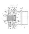
- FIG. 2 is a cross-sectional view of the constant velocity joint of Embodiment 1.
- FIG. 2 is a cross-sectional view of the constant velocity joint of Embodiment 1.
- the constant velocity joint 4 is held by an outer ring member 40, an inner ring member 50, a retainer 70 disposed between the outer ring member 40 and the inner ring member 50, and an open window portion 70a of the retainer 70. and a ball 60 that connects the inner ring member 50 .
- the tubular outer ring member 40 has a first outer ring end portion 40b on the first propelling shaft 2 side and a second outer ring end portion 40c on the second propelling shaft 3 side.
- the first outer ring end portion 40b is connected to the tubular first propulsion shaft 2 by a welded portion W.
- the inner circumference of the outer ring member 40 has a first outer ring groove end portion 40a1 on the first propelling shaft 2 side and a second outer ring groove end portion 40a2 on the second propelling shaft 3 side. , forming an outer ring groove portion 40a in which a ball (ball member) 60 is disposed.
- the outer ring groove portion 40a has an outer ring groove neutral position (position where the ball member is located) A that contacts the ball 60 between the first outer ring groove end portion 40a1 and the second outer ring groove end portion 40a2. Furthermore, the distance a from the outer ring groove neutral position A to the first outer ring groove end portion 40a1 is set longer than the distance b from the outer ring groove neutral position A to the second outer ring groove end portion 40a2 (a>b).
- the retainer 70 is provided on the inner peripheral side of the outer ring member 40 and has an open window portion 70 a that retains the balls 60 .
- the inner ring member 50 is provided on the inner peripheral side of the retainer 70 and connected to the stub shaft (second propulsion shaft) 3 .
- the outer circumference of the inner ring member 50 has a first inner ring groove end portion 50a1 on the first propelling shaft 2 side and a second inner ring groove end portion 50a2 on the second propelling shaft 3 side.
- the inner ring groove portion 50a which is inclined and recessed to intersect with the outer ring groove portion 40a, has a bottom portion 50e and a wall portion 50g, has an inner ring groove portion 50a in which the balls 60 are arranged, and an inner ring groove portion 50a at the end on the stub shaft 3 side.
- a small diameter portion 50c smaller in diameter than the bottom portion 50e of 50a and a jig engaging recess 50d smaller in diameter than the small diameter portion 50c are formed in the small diameter portion 50c.
- the inner ring groove portion 50a has an inner ring groove neutral position (position where the ball member is located) B that contacts the ball 60 between the first inner ring groove end portion 50a1 and the second inner ring groove end portion 50a2.
- the sliding amount can be secured efficiently.
- an angled portion 50f is provided on the outer periphery of the wall portion 50g of the first inner ring groove end portion 50a1 and the second inner ring groove end portion 50a2 of the inner ring groove portion 50a. Therefore, the strength of the inner ring member 50 can be increased by the angular portion 50f, so that the durability can be increased.
- a through hole 50b is formed in the inner periphery of the inner ring member 50, and a female spline portion 50i and a snap ring engagement groove portion 50j are formed in the inner peripheral surface of the through hole 50b.
- the stub shaft 3 has a male spline portion 3a and a snap ring accommodating groove 3b for holding the snap ring S on the outer peripheral surface of the end portion.
- the male spline portion 3a of the stub shaft 3 and the snap ring accommodating groove 3b holding the snap ring S are inserted into the through hole 50b of the inner ring member 50, and the male spline portion 3a of the stub shaft 3 is inserted into the female spline portion 50i of the inner ring member 50.
- the stub shaft 3 and the inner ring member 50 are connected and fixed by engaging the outer periphery of the snap ring S with the snap ring engagement groove portion 50j of the inner ring member 50.
- the outer diameter D2 of the wall portion 50g of the inner ring groove portion 50a of the inner ring member 50 is formed to be larger than the outer diameter D1 of the stub shaft 3.
- the outer ring groove neutral position A of the outer ring groove portion 40a of the outer ring member 40 where the ball 60 is located and the inner ring groove neutral position B of the inner ring groove portion 50a of the inner ring member 50 are positions where the stress acting on the boot 5 is minimized. Thereby, the durability of the boot 5 can be ensured, and the durability of the constant velocity joint 4 can be improved.
- FIG. 3 is a single part view of the inner ring member of the constant velocity joint of Embodiment 1.
- FIG. 3 is a single part view of the inner ring member of the constant velocity joint of Embodiment 1.
- FIG. 4 is a cross-sectional view showing a state of the constant velocity joint of Embodiment 1 at the time of collision. That is, at the time of a vehicle collision, the movement of the engine causes the stub shaft 3 and the inner ring member 50 to move in the direction F, the center C of the ball 60 is positioned at the second inner ring groove end portion 50a2 of the inner ring groove portion 50a, and the center C of the ball 60 is positioned at the second inner ring groove end portion 50a2 of the outer ring groove portion 40a. 1 It shows a state where it is located on the left side of the drawing by a distance e from the outer ring groove end portion 40a1.
- the ball 60 can be reliably pulled out between the outer ring 40 and the stub shaft 3 instead of the first propeller shaft 2 side, so that it can be prevented from being caught between the inner ring member 50 and the first propeller shaft 2. , an increase in the collision load can be suppressed.
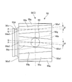
- FIG. 5 is a perspective view showing a state before the stub shaft is attached to the constant velocity joint of Embodiment 1.
- the jig 100 Before assembling and fixing the stub shaft 3 in the next step to the constant velocity joint 4 assembled with the retainer 70 holding the outer ring member 40, the inner ring member 50, and the balls 60 in the windows 70a, the jig 100 is installed.
- the engaging portion 100a is engaged with the jig engaging concave portion 50d of the inner ring member 50, and the contacting portion 100b of the jig 100 is brought into contact with the outer ring member 40, so that the relative movement between the inner ring member 50 and the outer ring member 40 is prevented. I try to suppress it.
- the stub shaft 3 is inserted into the through hole 50b of the inner ring member 50 in the next process, in the constant velocity joint 4 assembled with the retainer 70 holding the outer ring member 40, the inner ring member 50, and the balls 60 in the windows 70a. Since it can be inserted, the assembling workability of the propeller shaft 1 can be improved, and the reliability can also be improved.
- An outer ring groove formed in a cylindrical shape and recessed at an angle to the rotation axis P of the constant velocity joint 4 on the inner circumference of the outer ring member 40 to which the first propeller shaft 2 of the propeller shaft 1 is connected. 40a, a first outer ring groove end portion 40a1 on the first propelling shaft 2 side of the outer ring groove portion 40a, and a second outer ring groove end portion 40a2 on the second propelling shaft 3 side.
- An outer ring groove neutral position A is set between the two outer ring groove end portions 40a2, and a ball 60 arranged at the outer ring groove neutral position A, and a ball 60 provided on the inner peripheral side of the outer ring member 40, the second propeller shaft 1 propeller shaft 1 propeller shaft 1
- the outer circumference of the inner ring member 50 connected to the shaft 3 is inclined with respect to the rotation axis P of the constant velocity joint 4 and is recessed so as to intersect with the outer ring groove portion 40a.
- An inner ring groove portion 50a having a large outer diameter D2, a first inner ring groove end portion 50a1 of the inner ring groove portion 50a on the first propelling shaft 2 side, and a second inner ring groove end portion 50a2 on the second propelling shaft 3 side.
- the outer ring groove neutral position A of the outer ring groove portion 40a of the outer ring member 40 where the ball 60 is located and the inner ring groove neutral position B of the inner ring groove portion 50a of the inner ring member 50 are positions where the stress acting on the boot 5 is minimized. I made it Therefore, the durability of the boot 5 can be ensured, and the durability of the constant velocity joint 4 can be improved.
- a repair is performed.
- the engaging portion 100a of the jig 100 is engaged with the jig engaging concave portion 50d of the inner ring member 50, and the contact portion 100b of the jig 100 is brought into contact with the outer ring member 40, thereby separating the inner ring member 50 and the outer ring member 40. Suppresses relative movement.
- the stub shaft 3 is inserted into the through-hole 50b of the inner ring member 50 in the next step in the constant velocity joint 4 assembled with the retainer 70 holding the outer ring member 40, the inner ring member 50, and the balls 60 in the windows 70a. Therefore, the assembling workability of the propeller shaft 1 can be improved, and the reliability can also be improved.
- An angled portion 50f is provided on the outer periphery of the wall portion 50g of the first inner ring groove end portion 50a1 and the second inner ring groove end portion 50a2 of the inner ring groove portion 50a. Therefore, since the strength of the inner ring member 50 can be increased, the durability can be increased.
- FIG. 6 is a cross-sectional view showing assembly of the constant velocity joint of the second embodiment.
- the distance f from the inner ring groove neutral position B to the first inner ring groove end portion 50a1 is longer than the distance d from the inner ring groove neutral position B to the second inner ring groove end portion 50a2 (f> d) I am trying to set it. Since other configurations are the same as those of the first embodiment, the same configurations are denoted by the same reference numerals, and descriptions thereof are omitted.
- the first inner ring groove end portion 50a1 is It can serve as a receiving guide for the ball 60, and has the effect of improving the ease of assembly.
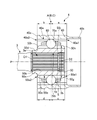
- FIG. 7 is a cross-sectional view of a constant velocity joint of Embodiment 3.
- FIG. 7 is a cross-sectional view of a constant velocity joint of Embodiment 3.
- the outer circumference of the wall portion 50g of the first inner ring groove end portion 50a1 and the second inner ring groove end portion 50a2 of the inner ring groove portion 50a is provided with the angular portion 50f, but in the third embodiment, the inner ring groove portion 50a.
- a chamfered portion 50h is provided on the outer periphery of the wall portion 50g of the first inner ring groove end portion 50a1 and the second inner ring groove end portion 50a2. Since other configurations are the same as those of the first embodiment, the same configurations are denoted by the same reference numerals, and descriptions thereof are omitted.
- the embodiment for carrying out the present invention has been described above, the specific configuration of the present invention is not limited to the configuration of the embodiment, and design changes, etc. within the scope of the invention may be made. is also included in the present invention.
- the outer periphery of both the wall portion 50g of the first inner ring groove end portion 50a1 or the second inner ring groove end portion 50a2 of the inner ring groove portion 50a is provided with an angular portion or a chamfered portion, but the inner ring groove portion 50a Only one outer circumference of the wall portion 50g of the first inner ring groove end portion 50a1 or the second inner ring groove end portion 50a2 may be provided with an angular portion or a chamfered portion.
- the present invention is not limited to the above-described embodiments, and includes various modifications.
- the above-described embodiments have been described in detail in order to explain the present invention in an easy-to-understand manner, and are not necessarily limited to those having all the configurations described.
- part of the configuration of one embodiment can be replaced with the configuration of another embodiment, and the configuration of another embodiment can be added to the configuration of one embodiment.
Landscapes
- Engineering & Computer Science (AREA)
- General Engineering & Computer Science (AREA)
- Mechanical Engineering (AREA)
- Shafts, Cranks, Connecting Bars, And Related Bearings (AREA)
- Motor Power Transmission Devices (AREA)
Priority Applications (3)
| Application Number | Priority Date | Filing Date | Title |
|---|---|---|---|
| DE112022004371.7T DE112022004371T5 (de) | 2021-09-10 | 2022-07-07 | Gleichlaufgelenk für Propellerwelle und eine Propellerwelle |
| US18/689,684 US20240418224A1 (en) | 2021-09-10 | 2022-07-07 | Constant velocity joint for propeller shaft and propeller shaft |
| CN202280059201.1A CN117897563A (zh) | 2021-09-10 | 2022-07-07 | 传动轴用等速接头以及传动轴 |
Applications Claiming Priority (2)
| Application Number | Priority Date | Filing Date | Title |
|---|---|---|---|
| JP2021147399A JP2023040442A (ja) | 2021-09-10 | 2021-09-10 | プロペラシャフト用の等速ジョイントおよびプロペラシャフト |
| JP2021-147399 | 2021-09-10 |
Publications (1)
| Publication Number | Publication Date |
|---|---|
| WO2023037744A1 true WO2023037744A1 (ja) | 2023-03-16 |
Family
ID=85506457
Family Applications (1)
| Application Number | Title | Priority Date | Filing Date |
|---|---|---|---|
| PCT/JP2022/026931 Ceased WO2023037744A1 (ja) | 2021-09-10 | 2022-07-07 | プロペラシャフト用の等速ジョイントおよびプロペラシャフト |
Country Status (5)
| Country | Link |
|---|---|
| US (1) | US20240418224A1 (https=) |
| JP (1) | JP2023040442A (https=) |
| CN (1) | CN117897563A (https=) |
| DE (1) | DE112022004371T5 (https=) |
| WO (1) | WO2023037744A1 (https=) |
Families Citing this family (1)
| Publication number | Priority date | Publication date | Assignee | Title |
|---|---|---|---|---|
| JP2023040443A (ja) * | 2021-09-10 | 2023-03-23 | 日立Astemo株式会社 | プロペラシャフト用の等速ジョイントおよびプロペラシャフト |
Citations (4)
| Publication number | Priority date | Publication date | Assignee | Title |
|---|---|---|---|---|
| JP2002250359A (ja) * | 2001-02-22 | 2002-09-06 | Ntn Corp | 等速自在継手 |
| JP2008087517A (ja) * | 2006-09-29 | 2008-04-17 | Jtekt Corp | 車両用プロペラシャフト |
| JP2010025316A (ja) * | 2008-07-24 | 2010-02-04 | Ntn Corp | 等速自在継手の内側継手部材、等速自在継手の組立方法、ドライブシャフトアッシー、およびプロペラシャフトアッシー |
| JP2018105328A (ja) * | 2016-12-22 | 2018-07-05 | Ntn株式会社 | 摺動式等速自在継手 |
Family Cites Families (3)
| Publication number | Priority date | Publication date | Assignee | Title |
|---|---|---|---|---|
| JP2018035896A (ja) | 2016-09-01 | 2018-03-08 | Ntn株式会社 | 等速自在継手および等速自在継手製造方法 |
| JP2021147399A (ja) | 2020-03-16 | 2021-09-27 | 日油株式会社 | 防曇剤組成物、該組成物から形成される防曇膜を有する防曇性物品 |
| JP2021148226A (ja) * | 2020-03-19 | 2021-09-27 | 株式会社ジェイテクト | 等速ジョイント |
-
2021
- 2021-09-10 JP JP2021147399A patent/JP2023040442A/ja not_active Abandoned
-
2022
- 2022-07-07 DE DE112022004371.7T patent/DE112022004371T5/de not_active Withdrawn
- 2022-07-07 WO PCT/JP2022/026931 patent/WO2023037744A1/ja not_active Ceased
- 2022-07-07 CN CN202280059201.1A patent/CN117897563A/zh active Pending
- 2022-07-07 US US18/689,684 patent/US20240418224A1/en active Pending
Patent Citations (4)
| Publication number | Priority date | Publication date | Assignee | Title |
|---|---|---|---|---|
| JP2002250359A (ja) * | 2001-02-22 | 2002-09-06 | Ntn Corp | 等速自在継手 |
| JP2008087517A (ja) * | 2006-09-29 | 2008-04-17 | Jtekt Corp | 車両用プロペラシャフト |
| JP2010025316A (ja) * | 2008-07-24 | 2010-02-04 | Ntn Corp | 等速自在継手の内側継手部材、等速自在継手の組立方法、ドライブシャフトアッシー、およびプロペラシャフトアッシー |
| JP2018105328A (ja) * | 2016-12-22 | 2018-07-05 | Ntn株式会社 | 摺動式等速自在継手 |
Also Published As
| Publication number | Publication date |
|---|---|
| CN117897563A (zh) | 2024-04-16 |
| DE112022004371T5 (de) | 2024-07-04 |
| US20240418224A1 (en) | 2024-12-19 |
| JP2023040442A (ja) | 2023-03-23 |
Similar Documents
| Publication | Publication Date | Title |
|---|---|---|
| KR101994661B1 (ko) | 등속조인트용 케이지 및 그 케이지 및 슬리브 일체형 내륜을 갖는 등속조인트 | |
| EP3763959B1 (en) | Power transmitting shaft | |
| JP2018009583A (ja) | 動力伝達軸 | |
| WO2023037744A1 (ja) | プロペラシャフト用の等速ジョイントおよびプロペラシャフト | |
| US8342971B2 (en) | Fixed type constant velocity universal joint | |
| WO2020179318A1 (ja) | プロペラシャフト | |
| WO2023037745A1 (ja) | プロペラシャフト用の等速ジョイントおよびプロペラシャフト | |
| US11359676B2 (en) | Fixed-type constant velocity universal joint | |
| JP5131064B2 (ja) | ボール型等速ジョイント | |
| WO2021177281A1 (ja) | プロペラシャフトの連結構造とその連結構造を有したプロペラシャフト | |
| JP4602177B2 (ja) | 等速自在継手 | |
| JP5163930B2 (ja) | ボール形等速ジョイント | |
| JP2008309245A (ja) | プロペラシャフト | |
| JP7344158B2 (ja) | 等速ジョイント、クロスグルーブ型等速ジョイント及び動力伝達軸 | |
| US20250327488A1 (en) | Constant velocity joint provided with grease retainer | |
| JP4637723B2 (ja) | 摺動式等速自在継手 | |
| CN111197623B (zh) | 等速万向节及其组装方法 | |
| JP2010001979A (ja) | 等速自在継手 | |
| KR102301016B1 (ko) | 등속 조인트 | |
| JP2009180286A (ja) | スプライン係合構造 | |
| KR20210010027A (ko) | 등속조인트용 부트 고정커버 및 그 부트 고정커버를 갖는 등속조인트 | |
| KR20210010421A (ko) | 등속조인트용 부트 고정커버 및 그 부트 고정커버를 갖는 등속조인트 | |
| JP5983812B2 (ja) | 十字軸式自在継手 | |
| JP2008002626A (ja) | 等速自在継手 | |
| JP2007056947A (ja) | 等速自在継手用フレキシブルブーツ |
Legal Events
| Date | Code | Title | Description |
|---|---|---|---|
| 121 | Ep: the epo has been informed by wipo that ep was designated in this application |
Ref document number: 22867068 Country of ref document: EP Kind code of ref document: A1 |
|
| WWE | Wipo information: entry into national phase |
Ref document number: 202280059201.1 Country of ref document: CN |
|
| WWE | Wipo information: entry into national phase |
Ref document number: 18689684 Country of ref document: US |
|
| 122 | Ep: pct application non-entry in european phase |
Ref document number: 22867068 Country of ref document: EP Kind code of ref document: A1 |