WO2023037585A1 - サーボパターン記録装置、サーボパターン記録方法、磁気テープの製造方法、磁気テープ - Google Patents
サーボパターン記録装置、サーボパターン記録方法、磁気テープの製造方法、磁気テープ Download PDFInfo
- Publication number
- WO2023037585A1 WO2023037585A1 PCT/JP2022/008608 JP2022008608W WO2023037585A1 WO 2023037585 A1 WO2023037585 A1 WO 2023037585A1 JP 2022008608 W JP2022008608 W JP 2022008608W WO 2023037585 A1 WO2023037585 A1 WO 2023037585A1
- Authority
- WO
- WIPO (PCT)
- Prior art keywords
- servo
- magnetic
- recording
- tape
- magnetic tape
- Prior art date
- Legal status (The legal status is an assumption and is not a legal conclusion. Google has not performed a legal analysis and makes no representation as to the accuracy of the status listed.)
- Ceased
Links
Images













Classifications
-
- G—PHYSICS
- G11—INFORMATION STORAGE
- G11B—INFORMATION STORAGE BASED ON RELATIVE MOVEMENT BETWEEN RECORD CARRIER AND TRANSDUCER
- G11B5/00—Recording by magnetisation or demagnetisation of a record carrier; Reproducing by magnetic means; Record carriers therefor
- G11B5/008—Recording on, or reproducing or erasing from, magnetic tapes, sheets, e.g. cards, or wires
- G11B5/00813—Recording on, or reproducing or erasing from, magnetic tapes, sheets, e.g. cards, or wires magnetic tapes
-
- G—PHYSICS
- G11—INFORMATION STORAGE
- G11B—INFORMATION STORAGE BASED ON RELATIVE MOVEMENT BETWEEN RECORD CARRIER AND TRANSDUCER
- G11B21/00—Head arrangements not specific to the method of recording or reproducing
- G11B21/02—Driving or moving of heads
- G11B21/10—Track finding or aligning by moving the head ; Provisions for maintaining alignment of the head relative to the track during transducing operation, i.e. track following
-
- G—PHYSICS
- G11—INFORMATION STORAGE
- G11B—INFORMATION STORAGE BASED ON RELATIVE MOVEMENT BETWEEN RECORD CARRIER AND TRANSDUCER
- G11B5/00—Recording by magnetisation or demagnetisation of a record carrier; Reproducing by magnetic means; Record carriers therefor
- G11B5/008—Recording on, or reproducing or erasing from, magnetic tapes, sheets, e.g. cards, or wires
-
- G—PHYSICS
- G11—INFORMATION STORAGE
- G11B—INFORMATION STORAGE BASED ON RELATIVE MOVEMENT BETWEEN RECORD CARRIER AND TRANSDUCER
- G11B5/00—Recording by magnetisation or demagnetisation of a record carrier; Reproducing by magnetic means; Record carriers therefor
- G11B5/008—Recording on, or reproducing or erasing from, magnetic tapes, sheets, e.g. cards, or wires
- G11B5/00813—Recording on, or reproducing or erasing from, magnetic tapes, sheets, e.g. cards, or wires magnetic tapes
- G11B5/00817—Recording on, or reproducing or erasing from, magnetic tapes, sheets, e.g. cards, or wires magnetic tapes on longitudinal tracks only, e.g. for serpentine format recording
- G11B5/00821—Recording on, or reproducing or erasing from, magnetic tapes, sheets, e.g. cards, or wires magnetic tapes on longitudinal tracks only, e.g. for serpentine format recording using stationary heads
- G11B5/00826—Recording on, or reproducing or erasing from, magnetic tapes, sheets, e.g. cards, or wires magnetic tapes on longitudinal tracks only, e.g. for serpentine format recording using stationary heads comprising a plurality of single poles or gaps or groups thereof operative at the same time
-
- G—PHYSICS
- G11—INFORMATION STORAGE
- G11B—INFORMATION STORAGE BASED ON RELATIVE MOVEMENT BETWEEN RECORD CARRIER AND TRANSDUCER
- G11B5/00—Recording by magnetisation or demagnetisation of a record carrier; Reproducing by magnetic means; Record carriers therefor
- G11B5/127—Structure or manufacture of heads, e.g. inductive
- G11B5/29—Structure or manufacture of unitary devices formed of plural heads for more than one track
-
- G—PHYSICS
- G11—INFORMATION STORAGE
- G11B—INFORMATION STORAGE BASED ON RELATIVE MOVEMENT BETWEEN RECORD CARRIER AND TRANSDUCER
- G11B5/00—Recording by magnetisation or demagnetisation of a record carrier; Reproducing by magnetic means; Record carriers therefor
- G11B5/48—Disposition or mounting of heads or head supports relative to record carriers ; arrangements of heads, e.g. for scanning the record carrier to increase the relative speed
- G11B5/58—Disposition or mounting of heads or head supports relative to record carriers ; arrangements of heads, e.g. for scanning the record carrier to increase the relative speed with provision for moving the head for the purpose of maintaining alignment of the head relative to the record carrier during transducing operation, e.g. to compensate for surface irregularities of the latter or for track following
- G11B5/584—Disposition or mounting of heads or head supports relative to record carriers ; arrangements of heads, e.g. for scanning the record carrier to increase the relative speed with provision for moving the head for the purpose of maintaining alignment of the head relative to the record carrier during transducing operation, e.g. to compensate for surface irregularities of the latter or for track following for track following on tapes
-
- G—PHYSICS
- G11—INFORMATION STORAGE
- G11B—INFORMATION STORAGE BASED ON RELATIVE MOVEMENT BETWEEN RECORD CARRIER AND TRANSDUCER
- G11B5/00—Recording by magnetisation or demagnetisation of a record carrier; Reproducing by magnetic means; Record carriers therefor
- G11B5/48—Disposition or mounting of heads or head supports relative to record carriers ; arrangements of heads, e.g. for scanning the record carrier to increase the relative speed
- G11B5/58—Disposition or mounting of heads or head supports relative to record carriers ; arrangements of heads, e.g. for scanning the record carrier to increase the relative speed with provision for moving the head for the purpose of maintaining alignment of the head relative to the record carrier during transducing operation, e.g. to compensate for surface irregularities of the latter or for track following
- G11B5/584—Disposition or mounting of heads or head supports relative to record carriers ; arrangements of heads, e.g. for scanning the record carrier to increase the relative speed with provision for moving the head for the purpose of maintaining alignment of the head relative to the record carrier during transducing operation, e.g. to compensate for surface irregularities of the latter or for track following for track following on tapes
- G11B5/588—Disposition or mounting of heads or head supports relative to record carriers ; arrangements of heads, e.g. for scanning the record carrier to increase the relative speed with provision for moving the head for the purpose of maintaining alignment of the head relative to the record carrier during transducing operation, e.g. to compensate for surface irregularities of the latter or for track following for track following on tapes by controlling the position of the rotating heads
- G11B5/592—Disposition or mounting of heads or head supports relative to record carriers ; arrangements of heads, e.g. for scanning the record carrier to increase the relative speed with provision for moving the head for the purpose of maintaining alignment of the head relative to the record carrier during transducing operation, e.g. to compensate for surface irregularities of the latter or for track following for track following on tapes by controlling the position of the rotating heads using bimorph elements supporting the heads
- G11B5/5921—Disposition or mounting of heads or head supports relative to record carriers ; arrangements of heads, e.g. for scanning the record carrier to increase the relative speed with provision for moving the head for the purpose of maintaining alignment of the head relative to the record carrier during transducing operation, e.g. to compensate for surface irregularities of the latter or for track following for track following on tapes by controlling the position of the rotating heads using bimorph elements supporting the heads using auxiliary signals, e.g. pilot signals
- G11B5/5926—Disposition or mounting of heads or head supports relative to record carriers ; arrangements of heads, e.g. for scanning the record carrier to increase the relative speed with provision for moving the head for the purpose of maintaining alignment of the head relative to the record carrier during transducing operation, e.g. to compensate for surface irregularities of the latter or for track following for track following on tapes by controlling the position of the rotating heads using bimorph elements supporting the heads using auxiliary signals, e.g. pilot signals recorded in separate tracks, e.g. servo tracks
-
- G—PHYSICS
- G11—INFORMATION STORAGE
- G11B—INFORMATION STORAGE BASED ON RELATIVE MOVEMENT BETWEEN RECORD CARRIER AND TRANSDUCER
- G11B5/00—Recording by magnetisation or demagnetisation of a record carrier; Reproducing by magnetic means; Record carriers therefor
- G11B5/62—Record carriers characterised by the selection of the material
- G11B5/68—Record carriers characterised by the selection of the material comprising one or more layers of magnetisable material homogeneously mixed with a bonding agent
- G11B5/70—Record carriers characterised by the selection of the material comprising one or more layers of magnetisable material homogeneously mixed with a bonding agent on a base layer
-
- G—PHYSICS
- G11—INFORMATION STORAGE
- G11B—INFORMATION STORAGE BASED ON RELATIVE MOVEMENT BETWEEN RECORD CARRIER AND TRANSDUCER
- G11B5/00—Recording by magnetisation or demagnetisation of a record carrier; Reproducing by magnetic means; Record carriers therefor
- G11B5/74—Record carriers characterised by the form, e.g. sheet shaped to wrap around a drum
- G11B5/78—Tape carriers
Definitions
- This technology relates to a servo pattern recording device, a servo pattern recording method, a magnetic tape manufacturing method, and a magnetic tape.
- magnetic recording media have been widely used for purposes such as backing up electronic data.
- a magnetic tape cartridge is attracting more and more attention as a storage medium for big data and the like because of its large capacity and long-term storage capability.
- a magnetic tape conforming to the LTO (Linear Tape Open) standard is provided with multiple data bands parallel to the longitudinal direction of the tape, and data is recorded on multiple recording tracks within these multiple data bands. Further, the magnetic tape is provided with a plurality of servo bands parallel to the longitudinal direction of the tape, and each data band is arranged on the magnetic layer so as to be sandwiched between the plurality of servo bands. Each servo band carries out positioning (tracking) control of the recording/reproducing head with respect to each recording track, and furthermore, there is a servo pattern of a predetermined shape in which tape information and servo band identification information for specifying the data band are embedded. Recorded.
- LTO Linear Tape Open
- Magnetic tapes are typically manufactured through processes such as coating a base film with a magnetic material, calendering, cutting, and recording servo patterns. Since these treatments are performed while the base film is being wound with a constant tension, the completed magnetic tape has internal strain and tends to widen with the passage of time. Therefore, when data is recorded or reproduced by a tape drive device, even if the magnetic tape is run with the same tension as when recording the servo pattern, the width of the magnetic tape is the same as the width of the magnetic tape when recording the servo pattern. It may increase more than the dimension. In this case, the interval between adjacent servo bands (hereinafter also referred to as servo band pitch) changes, making it difficult to achieve desired tracking control.
- servo band pitch the interval between adjacent servo bands
- the servo band pitch for each data band is not always the same under the same tension. Since the servo band pitch for each data band depends on the tension of the magnetic tape, when the servo band pitch differs between data bands, it is highly likely that the tension distribution in the width direction of the magnetic tape is related. However, it is difficult to directly measure and grasp the tension distribution. Therefore, it is desirable to be able to adjust the servo band pitch by a method other than tension adjustment in the tape drive device.
- an object of the present technology is to provide a servo pattern recording apparatus, a servo pattern recording method, a magnetic tape manufacturing method, and a magnetic tape that can adjust the servo band pitch by a method other than tension adjustment. That's what it is.
- a servo pattern recording device is a device that records a plurality of servo patterns adjacent to each other in a tape width direction on a magnetic layer of a magnetic tape, and includes a servo write head and a temperature adjustment unit.
- the servo write head has a plurality of recording sections respectively arranged corresponding to a plurality of servo bands of the magnetic layer on which the plurality of servo patterns are recorded.
- the temperature adjustment section is configured to be able to adjust temperatures of the plurality of recording sections individually.
- the servo pattern recording apparatus is provided with a temperature control unit, it is possible to adjust the arrangement pitch of the servo patterns recorded on the magnetic layer of the magnetic tape by the recording unit by utilizing the thermal expansion or thermal contraction of the recording unit. can.
- the temperature adjustment section individually adjusts the temperatures of the plurality of recording sections so that an average value of differences over the entire length of the tape between two adjacent servo band pitches in the plurality of servo bands is equal to or less than a predetermined value.
- the predetermined value is, for example, 100 nm.
- the temperature adjustment section may have a heating mechanism capable of individually raising the temperatures of the plurality of recording sections.
- the plurality of recording units include a plurality of magnetic cores having magnetic gaps, and a plurality of coils wound around the plurality of magnetic cores, and the heating mechanism is a current flowing through the plurality of coils.
- the temperature adjustment section may have a cooling mechanism capable of individually cooling the plurality of recording sections.
- the plurality of recording units include a plurality of magnetic cores having magnetic gaps and a plurality of coils wound around the plurality of magnetic cores, and the cooling mechanism individually distributes the magnetic cores to the plurality of coils.
- a blower unit capable of supplying cooling gas may be included.
- the servo write head may have a recording surface for recording the servo pattern on the magnetic tape by the magnetic gap.
- the recording surface has a first region corresponding to a position where the magnetic gap is provided in the length direction and a width direction perpendicular to the length direction corresponding to the position where the magnetic gap is not provided in the length direction. and a second region provided with a plurality of grooves crossing from one end of the above to the other end in the width direction.
- a servo pattern recording method is a method for recording a plurality of servo patterns adjacent to each other in a tape width direction on a magnetic layer of a magnetic tape, running the magnetic tape; Individually adjust the temperature of multiple recording sections of the servo write head, The plurality of servo patterns are recorded on the magnetic layer by the plurality of recording units.
- the temperature of the plurality of recording portions so that the average value of the difference over the entire length of the tape between the pitches of two adjacent servo bands in the plurality of servo bands of the magnetic layer in which the plurality of servo patterns are recorded is equal to or less than a predetermined value. may be adjusted individually.
- the plurality of recording units include a plurality of magnetic cores having magnetic gaps and a plurality of coils wound around the plurality of magnetic cores, In the step of adjusting temperatures of the plurality of recording units, power supplied to at least one of the plurality of coils may be larger than power supplied to other coils.
- the plurality of recording units include a plurality of magnetic cores having magnetic gaps and a plurality of coils wound around the plurality of magnetic cores,
- the step of adjusting the temperatures of the plurality of recording units may include supplying cooling gas to at least one of the plurality of coils at a flow rate greater than that of the other coils.
- a method for manufacturing a magnetic tape according to one embodiment of the present technology is a method for manufacturing a magnetic tape in which a plurality of servo patterns adjacent to each other in a tape width direction are recorded on a magnetic layer of the magnetic tape, the method comprising: running the magnetic tape; Individually adjust the temperature of multiple recording sections of the servo write head, The plurality of servo patterns are recorded on the magnetic layer by the plurality of recording units.
- a magnetic tape according to one embodiment of the present technology is a magnetic tape in which a plurality of servo patterns adjacent to each other in a tape width direction are recorded on a magnetic layer of the magnetic tape, In the plurality of servo bands, an average value of differences of two adjacent servo band pitches over the entire length of the tape is 100 nm or less.
- the Young's modulus of the magnetic tape is, for example, 8 GPa or less.
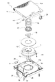
- FIG. 1 is an exploded perspective view of a tape cartridge according to an embodiment of the present technology
- FIG. FIG. 3 is a schematic diagram of the magnetic tape as viewed from the side
- 2 is a schematic diagram of the magnetic tape as viewed from above (magnetic layer side)
- FIG. 4 is an enlarged view showing recording tracks in the data band of the magnetic tape
- FIG. 4 is an enlarged view showing a part of the servo pattern written on the servo band of the magnetic tape
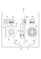
- FIG. 1 is a schematic diagram showing an example of the configuration of a tape drive device
- FIG. 3 is a schematic view of the drive head in the tape drive device viewed from below (tape running surface);
- FIG. 3 is a diagram showing a state when a first drive head section in the drive head is recording/reproducing data signals;
- (A) is a schematic plan view showing an example of arrangement of servo patterns, and
- (B) is a diagram showing the reproduced waveform.
- 4 is a schematic diagram showing a configuration example of a servo pattern (A) in which first servo band identification information is embedded and a servo pattern (B) in which second servo band identification information is embedded;
- FIG. 4A and 4B are diagrams showing a reproduced waveform (A) of a first servo pattern and a reproduced waveform (B) of a second servo pattern;
- FIG. 10 is an explanatory diagram of a drive head tracking a data band; It is a figure explaining the measuring method of a servo trace line.
- 1 is a schematic front view showing a servo pattern recording device according to an embodiment of the present technology; FIG. It is a partially enlarged view showing a part of the servo pattern recording device.
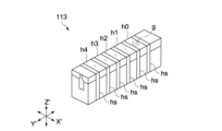
- 3 is a perspective view schematically showing the configuration of a servo write head in the servo pattern recording device;
- FIG. 4 is a schematic cross-sectional view of the main part of the servo write head;
- FIG. 4 is a schematic plan view of the main part of the servo write head;
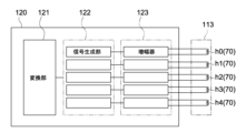
- FIG. It is a block diagram which shows the structure of the drive part in the said servo pattern recording device.
- FIG. 4 is a schematic diagram showing a recording signal waveform (A) of a first servo subframe in a first pulse signal and a recording signal waveform of a first servo subframe in a second pulse signal;
- FIG. 2 is a perspective view schematically showing a pair of guide rollers for guiding travel of the magnetic tape in the servo pattern recording device; It is one experimental result showing a comparison of the servo band pitches of the data bands measured for the same magnetic tape. It is an experimental result showing the relationship between the magnitude of the recording current of the servo pattern and the servo band pitch. This is an experimental result showing the relationship between the magnitude of the recording current, the temperature change of the servo write head, and the running time of the magnetic tape.
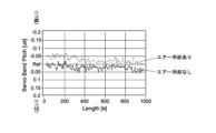
- FIG. 4 is a schematic perspective view showing the configuration of a servo write head provided with a blower unit; It is an experimental result showing how the servo pattern pitch changes depending on whether cooling gas (air) is introduced or not.
- 3 is a diagram showing the maximum value (max) and minimum value (min) of servo band pitch, which is the interval between two adjacent servo bands, and the difference between these maximum and minimum values (servo band pitch difference: SBD); FIG. This is the result of an experiment conducted without cooling the servo write head.
- FIG. 28 is similar to FIG.
- FIG. 28 is similar to FIG. 28 and shows the results of another experiment performed while cooling the servo write head.
- FIG. 4 is a schematic plan view of a servo write head having a plurality of grooves; It is an expansion perspective view which shows the detail of the said groove part.
- FIG. 32 is a schematic plan view showing a modification of the configuration of the servo write head shown in FIG. 31;
- FIG. 2 is an explanatory diagram of the particle shape of hexagonal ferrite, which is a magnetic powder;
- FIG. 1 is an exploded perspective view showing a tape cartridge 10 according to one embodiment of the present technology.
- the tape cartridge 10 a tape cartridge complying with the LTO standard will be described as an example.
- the tape cartridge 10 includes a cartridge case 11, a tape reel 13, and a magnetic tape 1.
- the cartridge case 11 is constructed by connecting an upper shell 11a and a lower shell 11b with a plurality of screw members.
- a single tape reel 13 around which the magnetic tape 1 is wound is rotatably accommodated inside the cartridge case 11 .
- a chucking gear (not shown) that engages with the spindle 31 (see FIG. 6) of the tape drive device 30 is annularly formed in the center of the bottom of the tape reel 13 .
- This chucking gear is exposed to the outside through an opening 14 formed in the center of the lower shell 11b.
- An annular metal plate 15 that is magnetically attracted to the spindle 31 is fixed to the inner peripheral side of the chucking gear.
- a reel spring 16 Between the inner surface of the upper shell 11a and the tape reel 13, a reel spring 16, a reel lock member 17 and a spider 18 are arranged. These constitute a reel lock mechanism that prevents rotation of the tape reel 13 when the cartridge 10 is not in use.
- One side wall of the cartridge case 11 is provided with a tape pull-out port 19 for pulling out one end of the magnetic tape 1 to the outside.
- a slide door 20 for opening and closing the tape outlet 19 is arranged inside the side wall.
- the slide door 20 is configured to slide in the direction of opening the tape outlet 19 against the urging force of the torsion spring 21 by engagement with a tape loading mechanism (not shown) of the tape drive device 30 .
- a leader pin 22 is fixed to one end of the magnetic tape 1 .
- the leader pin 22 is detachably attached to a pin holding portion 23 provided inside the tape outlet 19 .
- the pin holding portion 23 elastically holds the upper end portion and the lower end portion of the leader pin 22 on the inner surface of the upper wall (the inner surface of the upper shell 11a) and the inner surface of the bottom wall (the inner surface of the lower shell 11b) of the cartridge case 11, respectively.
- a retainer 24 is provided.
- a safety tab 25 for preventing erroneous erasure of information recorded on the magnetic tape 1 is provided inside the other side wall of the cartridge case 11.
- a cartridge memory 9 capable of reading and writing without contact is arranged inside the other side wall of the cartridge case 11.
- FIG. 2 is a schematic diagram of the magnetic tape 1 viewed from the side
- FIG. 3 is a schematic diagram of the magnetic tape 1 viewed from above (magnetic layer 43 side).
- the magnetic tape 1 is long in the longitudinal direction (X-axis direction), short in the width direction (Y-axis direction), and thin in the thickness direction (Z-axis direction). ing.
- the magnetic tape 1 includes a tape-shaped substrate 41 elongated in the longitudinal direction (X-axis direction), an underlayer (non-magnetic layer) 42 provided on one main surface of the substrate 41, and a It includes a magnetic layer 43 provided and a back layer 44 provided on the other main surface of the substrate 41 .
- the back layer 44 may be provided as required, and the back layer 44 may be omitted.
- the magnetic tape 1 may be a perpendicular recording magnetic recording medium or a longitudinal recording magnetic recording medium.
- the magnetic layer 43 may be a coated film of a magnetic material, or may be a deposited film or a sputtered film of a magnetic material. Details of each layer constituting the magnetic tape 1 will be described later.
- the magnetic layer 43 includes a plurality of data bands d (data bands d0 to d3) elongated in the longitudinal direction (X-axis direction) in which data is written, and a plurality of longitudinally elongated bands d0 to d3 in which the servo pattern 6 is written. of servo bands s (servo bands s0 to s4).
- the servo bands s are arranged at positions sandwiching the data bands d in the width direction (Y-axis direction).
- the ratio of the area of the servo band s to the area of the entire surface of the magnetic layer 43 is typically 4.0% or less.
- the width of the servo band s is 1/2 inch tape width, for example, 96 ⁇ m or less.
- the ratio of the area of the servo band s to the area of the entire surface of the magnetic layer 43 can be obtained, for example, by developing the magnetic tape 1 using a developer such as a ferricolloid developer, and then observing the developed magnetic tape 1 with an optical microscope. It can be measured by observation.
- the number of data bands d is four and the number of servo bands s is five.
- the number of data bands d and the number of servo bands s can be changed as appropriate.
- the data band d includes a plurality of recording tracks 5 that are long in the longitudinal direction and aligned in the width direction.
- the number of recording tracks 5 included in one data band d is, for example, approximately 1,000 to 2,500. Data is recorded within the recording track 5 along this recording track 5 .
- One bit length in the longitudinal direction of the data recorded in the data band d is, for example, 48 nm or less.
- the servo band s includes a servo pattern 6 having a predetermined shape recorded by a servo pattern recording device (see FIG. 14), which will be described later.
- the number of recording tracks 5 increases with each generation, and the recording capacity is dramatically improved.
- the number of recording tracks 5 in the original LTO-1 was 384, but the number of recording tracks 5 in LTO-2 to LTO-8 was 512, 704, 896, and 896, respectively. 1280, 2176, 3584 and 6656.
- the data recording capacity was 100 GB (gigabytes) for LTO-1, but 200 GB, 400 GB, 800 GB, 1.5 TB (terabytes), and 2.5 TB for LTO-2 to LTO-8 respectively. , 6.0 TB and 12 TB.
- the number of recording tracks 5 and the recording capacity are not particularly limited, and can be changed as appropriate.
- a magnetic tape 1 that has a large number of recording tracks 5 and a large recording capacity (e.g., 6656 or more, 12 TB or more: LTO8 or later) and is susceptible to fluctuations in the width of the magnetic tape 1.
- a magnetic tape having a Young's modulus of the entire tape (Young's modulus in the longitudinal direction of the tape) of 8 GPa or less is applied as the magnetic tape 1.
- FIG. 4 is an enlarged view showing the recording track 5 in the data band d.
- the recording tracks 5 are long in the longitudinal direction, aligned in the width direction, and have a predetermined recording track width (track pitch) Wd for each track in the width direction.
- This recording track width Wd is set to 2.0 ⁇ m or less in LTO-8. Note that such a recording track width Wd can be obtained, for example, by developing the magnetic layer 43 of the magnetic tape 1 using a developer such as a ferricoloid developer, and then observing the developed magnetic layer 43 of the magnetic tape 1 with an optical microscope.
- Width Wd can be measured.
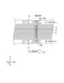
- FIG. 5 is an enlarged view showing a part of the servo pattern 6 written in the servo band s.
- the servo pattern 6 includes a plurality of stripes inclined at a predetermined azimuth angle ⁇ with respect to the width direction (Y-axis direction), details of which will be described later.
- the plurality of stripes are classified into a first stripe group 61 inclined clockwise with respect to the width direction (Y-axis direction) and a second stripe group 62 inclined counterclockwise with respect to the width direction. be.
- First stripe group 61 and second stripe group 62 typically include four or five stripes.
- the shape of the servo pattern 6 can be determined, for example, by developing the magnetic layer 43 of the magnetic tape 1 using a developer such as a ferricolloid developer, and then observing the developed magnetic layer 43 of the magnetic tape 1 with an optical microscope. It can be measured by observation.
- a developer such as a ferricolloid developer
- a servo trace line T which is a line traced on the servo pattern 6 by a servo read head 132 (see FIG. 7), which will be described later, is indicated by a dashed line.
- the servo trace lines T are set along the longitudinal direction (X-axis direction) and are set at predetermined intervals Ps in the width direction.
- the number of servo trace lines T per one servo band s is, for example, about 30 to 60.
- the interval Ps between two adjacent servo trace lines T is the same as the recording track width Wd, for example, 2.0 ⁇ m or less.
- the interval Ps between two adjacent servo trace lines T is a value that determines the recording track width Wd. That is, when the interval Ps between the servo trace lines T is narrowed, the recording track width Wd is reduced and the number of recording tracks 5 included in one data band d is increased. As a result, the data recording capacity increases.
- FIG. 6 is a diagram showing the tape drive device 30. As shown in FIG.
- the tape drive device 30 is a data recording/reproducing device capable of recording data on the magnetic tape 1 or reproducing data recorded on the magnetic tape 1 .
- the tape drive device 30 is configured so that the cartridge 10 can be loaded.
- the tape drive device 30 is configured to be able to load one cartridge 10, but may be configured to be capable of loading a plurality of cartridges 10 at the same time.
- the tape drive device 30 includes a spindle 31, a take-up reel 32, a spindle drive device 33, a reel drive device 34, a plurality of guide rollers 35, a drive head 36, a reader/writer 37, and a control device 38. Prepare.
- the tape drive device 30 may further include a thermometer 39, a hygrometer 40, and the like.
- the spindle 31 has a head portion that engages the chucking gear of the tape reel 13 through the opening 14 formed in the lower shell 11b of the cartridge 10.
- the spindle 31 raises the tape reel 13 by a predetermined distance against the urging force of the reel spring 16 to release the reel lock function of the reel lock member 17 .
- the tape reel 13 is rotatably supported inside the cartridge case 11 by the spindle 31 .
- the spindle driving device 33 rotates the spindle 31 according to a command from the control device 38.
- the take-up reel 32 is configured to be capable of fixing the leading end (leader pin 22) of the magnetic tape 1 pulled out from the cartridge 10 via a tape loading mechanism (not shown).
- a plurality of guide rollers 35 guide the running of the magnetic tape 1 so that the tape path formed between the cartridge 10 and the take-up reel 32 has a predetermined relative positional relationship with respect to the drive head 36 .
- the reel driving device 34 rotates the take-up reel 32 according to a command from the control device 38 .
- the running direction of the magnetic tape 1 is the forward direction indicated by arrow A1 in FIG. rewinding direction toward the reel 13 side).
- the rotation of the spindle 31 by the spindle drive device 33 and the rotation of the take-up reel 32 by the reel drive device 34 are controlled to control the longitudinal direction (X-axis direction) of the magnetic tape 1 during data recording/reproducing.
- the tension at is adjustable.
- the tension of the magnetic tape 1 is adjusted by controlling the movement of the guide roller 35, a tension control unit including a dancer roller, etc. instead of controlling the rotation of the spindle 31 and the take-up reel 32 (or in addition to this control). may be done.
- the tension during running of the magnetic tape 1 is typically set to the same value as the tension when the servo pattern 6 is recorded on the magnetic tape 1 by the servo pattern recording device 100 (hereinafter also referred to as the reference tension). be.
- the tape drive device 30 by configuring the tape drive device 30 so that the tension can be adjusted, it is possible to cope with changes in the width dimension of the magnetic tape 1 caused by internal distortion of the magnetic tape 1 and changes over time. Specifically, when the width dimension of the magnetic tape 1 changes in the widening direction, the tension is adjusted higher than the reference tension, and when the servo band pitch changes in the narrowing direction, the tension is adjusted lower than the reference tension. do.
- the cartridge memory 9 stores information about the reference tension during servo pattern recording and the width dimension of the magnetic tape 1 at the reference tension.
- the reader/writer 37 is configured to be able to record management information in the cartridge memory 9 according to commands from the control device 38 . Also, the reader/writer 37 is configured to be able to read the management information from the cartridge memory 9 according to a command from the control device 38 .
- the management information includes product information of the tape cartridge 10 and the magnetic tape 1, usage history information, an outline of information recorded on the magnetic tape 1, and the like.
- the product information includes manufacturing information, the number of recording tracks 5 on the magnetic tape 1, unique information such as an ID.
- the usage history information includes access date and time, address information, communication history with the reader/writer 37, presence/absence of abnormality during loading/unloading of the tape drive device 30, and the like.
- the ISO14443 method is adopted as a communication method between the reader/writer 37 and the cartridge memory 9.
- the control device 38 includes, for example, a control section, a storage section, a communication section, and the like.
- the control unit is composed of, for example, a CPU (Central Processing Unit) or the like, and comprehensively controls each unit of the tape drive device 30 according to a program stored in the storage unit.
- CPU Central Processing Unit
- the storage unit includes a non-volatile memory in which various data and various programs are recorded, and a volatile memory used as a work area for the control unit.
- the various programs described above may be read from a portable recording medium such as an optical disk or a semiconductor memory, or may be downloaded from a server device on a network.
- the storage unit temporarily or non-temporarily stores the information read from the reader/writer 37 in the cartridge memory 9, the outputs of the thermometer 39 and the hygrometer 40, and the like.
- the communication unit is configured to be able to communicate with other devices such as a PC (Personal Computer) and a server device.
- the drive head 36 is configured to be able to record data on the magnetic tape 1 according to commands from the control device 38 . Further, the drive head 36 is configured to be able to reproduce data written on the magnetic tape 1 according to commands from the control device 38 .
- the drive head 36 is composed of a head unit having, for example, two servo read heads, a plurality of data write/read heads, and the like.
- FIG. 7 is a schematic view of the drive head 36 viewed from below (tape running surface).
- the drive head 36 includes a first drive head portion 36a and a second drive head portion 36b.
- the first drive head portion 36a and the second drive head portion 36b are configured symmetrically in the X'-axis direction (running direction of the magnetic tape 1 (the X-axis direction in FIG. 3)).
- the first drive head portion 36a and the second drive head portion 36b are configured to be movable in the Y'-axis direction (the width direction of the magnetic tape 1 (the Y-axis direction in FIG. 3)).
- the first drive head portion 36a is a drive head used when the magnetic tape 1 is running in the forward direction (the A1 direction in FIG. 6).
- the second drive head portion 36b is a drive head that is used when the magnetic tape 1 is running in the opposite direction (direction A2 in FIG. 6). Since the first drive head portion 36a and the second drive head portion 36b have basically the same configuration, the first drive head portion 36a will be described as a representative.
- the first drive head section 36 a has a head body 131 , two servo read heads 132 and a plurality of data write/read heads 133 .
- the servo read head 132 is configured to read the magnetic flux generated from the magnetic information recorded in the servo band s of the magnetic tape 1 by means of an MR element (MR: Magneto Resistive effect) or the like, thereby reproducing the servo signal. . That is, the servo signal is reproduced by reading the servo pattern 6 recorded on the servo band s by the servo read head 132 .
- MR Magneto Resistive effect
- the servo read heads 132 are provided on each side of the head body 131 in the width direction (the Y'-axis direction in FIG. 7).
- MR elements include anisotropic magneto resistive effect (AMR), giant magneto resistive effect (GMR), and tunnel magneto resistive effect (TMR).
- AMR anisotropic magneto resistive effect
- GMR giant magneto resistive effect
- TMR tunnel magneto resistive effect
- the servo read head pitch P1 which is the interval in the width direction (Y′-axis direction) between the two servo read heads 132, is the center of the standard value of the distance (servo band pitch) between two adjacent servo bands s on the magnetic tape 1. value (2858.8 ⁇ m).
- the data write/read heads 133 are arranged at equal intervals along the width direction (Y'-axis direction). Also, the data write/read head 133 is arranged at a position sandwiched between the two servo read heads 132 .
- the number of data write/read heads 133 is, for example, about 20 to 40, but the number is not particularly limited, and is 32 (32 channels) in this embodiment.
- the data write/read head 133 includes a data write head 134 and a data read head 135 .
- the data write head 134 is configured to be able to record data signals on the data band d of the magnetic tape 1 by the magnetic field generated from the magnetic gap.
- the data read head 135 is configured to read a magnetic field generated from the magnetic information recorded on the data band d of the magnetic tape 1 by means of an MR element or the like, thereby reproducing data signals.
- MR elements include anisotropic magnetoresistive elements (AMR), giant magnetoresistive elements (GMR), tunnel magnetoresistive elements (TMR), and the like.
- the data write head 134 is arranged on the left side of the data read head 135 (on the upstream side when the magnetic tape 1 flows in the forward direction).
- the data write head 134 is arranged on the right side of the data read head 135 (on the upstream side when the magnetic tape 1 flows in the opposite direction).
- the data read head 135 can reproduce the data signal immediately after the data write head 134 writes the data signal on the magnetic tape 1 .
- the data signal written by the data write head 134 of the first drive head section 36a may be reproduced by the data read head 135 of the second drive head section 36b.
- FIG. 8 is a diagram showing a state when the first drive head section 36a is recording/reproducing data signals.
- the example shown in FIG. 8 shows the magnetic tape 1 running in the forward direction (direction A1).
- one of the two servo read heads 132 is one of the two servo bands s. Positioned on one servo band s, the servo pattern 6 on this servo band s is read. The other servo read head 132 of the two servo read heads 132 is positioned on the other servo band s of the two adjacent servo bands s and reads the servo pattern 6 on this servo band s.
- the control device 38 determines whether the servo read head 132 is accurately tracing the target servo trace line T (see FIG. 5).
- the first stripe group 61 and the second stripe group 62 in the servo pattern 6 are inclined in opposite directions with respect to the width direction (Y-axis direction). Therefore, in the upper servo trace line T, the distance in the longitudinal direction (X-axis direction) between the first stripe group 61 and the second stripe group 62 is relatively narrow. On the other hand, on the lower servo trace line T, the distance in the longitudinal direction (X-axis direction) between the first stripe group 61 and the second stripe group 62 is relatively wide.
- the servo read head 132 can detect the magnetic tape 1. It is possible to know the current position in the width direction (Y-axis direction).
- the control device 38 can determine whether the servo read head 132 is accurately tracing the intended servo trace line T based on the reproduced waveform of the servo pattern 6 . If the servo read head 132 does not accurately trace the target servo trace line T, the control device 38 moves the drive head 36 in the width direction (Y'-axis direction) to 36 position or tracking adjustment. A method of measuring the servo trace line T traced by the servo read head 132 will be described later (see FIGS. 12 and 13).
- the data write/read head 133 adjusts its position along the servo trace line T to produce a data signal in the recording track 5. record.
- the magnetic tape 1 When the magnetic tape 1 is completely pulled out from the tape cartridge 10, the magnetic tape 1 is now run in the opposite direction (direction A2).
- the second drive head portion 36b As the servo trace line T, the servo trace line T adjacent to the previous servo trace line T is used.
- the data signal is recorded by the data write head 134 of the second drive head section 36b on the recording track 5 adjacent to the recording track 5 on which the data signal was previously recorded.
- data signals are recorded on the recording tracks 5 while the magnetic tape 1 is reciprocated many times by changing the running direction between the forward and reverse directions.
- the number of servo trace lines T is 100 and the number of data write/read heads 133 included in the first drive head section 36a (or the second drive head section 36b) is 32.
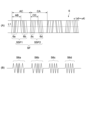
- FIG. 9(A) is a schematic plan view showing an arrangement example of the servo pattern 6, and FIG. 9(B) is a diagram showing its reproduced waveform.
- the servo pattern includes a plurality of azimuthal slope patterns of two or more different shapes.
- the position of the servo read head 132 is recognized based on the time interval between reading two tilt patterns with different shapes and the time interval between reading two tilt patterns with the same shape. Based on the position of the servo read head 132 thus recognized, the position of the drive head 36 in the width direction (Y-axis direction) of the magnetic tape 1 is controlled (see FIGS. 7 and 8).
- the servo pattern 6 forms a servo frame SF having a first servo subframe SSF1 and a second servo subframe SSF2.
- the servo frames SF are arranged in the longitudinal direction of the magnetic tape 1 at predetermined intervals along the longitudinal direction of the tape.
- Each servo frame SF encodes one bit of '1' or '0'. That is, one servo frame SF corresponds to one bit.
- the first servo subframe SSF1 is composed of an A burst 6a and a B burst 6b.
- the A burst 6a is composed of five linear patterns (corresponding to the first stripe group 61 in FIG. 5) inclined in the first direction with respect to the longitudinal direction of the tape
- the B burst 6b is composed of the above-mentioned first stripes in the longitudinal direction of the tape. It consists of five linear patterns (corresponding to the second stripe group 62 in FIG. 5) inclined in the second direction opposite to the first direction.
- the second servo subframe SSF2 is composed of a C burst 6c and a D burst 6d.
- the C burst 6c is composed of four linear patterns (corresponding to the first stripe group 61 in FIG. 5) inclined in the first direction
- the D burst 6d is composed of four linear patterns inclined in the second direction. It consists of a linear pattern (corresponding to the second stripe group 62 in FIG. 5).
- the length of the servo frame SF and the servo subframes SSF1 and SSF2, the arrangement interval of the inclined portions that incline the bursts 6a to 6d, etc. can be arbitrarily set according to the type and specifications of the magnetic tape.
- the reproduction waveform of the servo pattern 6 typically exhibits a burst waveform as shown in FIG.
- Signal S6d corresponds to D burst 6d.
- a position error signal is generated by reading servo patterns 6 on two servo bands adjacent to one data band, and Properly position the read/write head relative to the recording track.
- the servo pattern 6 is read from the magnetic tape 1 running at a predetermined speed, and the distance (time interval) AC between the A burst 6a and the C burst 6c, which are arrays of inclined patterns of the same type, and The ratio of the distance (time interval) AB between the A burst 6a and the B burst 6b, which are arrays of different-shaped gradient patterns (or the distance CA between the C burst 6c and the A burst 6a, and the C burst 6c and the distance CD to the D burst 6d) is calculated, and the drive head 36 is moved in the tape width direction (Y'-axis direction) so that the value becomes the set value determined for each recording track (Fig. 8).
- Servo band identification information Different combinations of servo band identification information are written for each data band in each servo band s (s0 to s4).
- a combination of servo band identification information obtained from two servo bands s2 and s3 adjacent to data band d0 is a combination of servo band identification information obtained from servo bands s1 and s2 adjacent to data band d1 and data band
- the combination of servo band identification information obtained from servo bands s3 and s4 adjacent to data band d2 is different from the combination of servo band identification information obtained from two servo bands s0 and s1 adjacent to data band d3.
- the servo band identification information is embedded in the servo band.
- the servo band identification information is multi-bit information, typically 4 bits, but may be 8 bits or other multi-bits other than 4 bits and 8 bits.
- the two types of servo bands include a first servo band in which first servo band identification information is recorded and a second servo band in which second servo band identification information is recorded.
- the first servo band identification information is 4-bit information (eg, "1001")
- the second servo band identification information is 4-bit information (eg, "0111") different from the first servo band identification information. ).
- a combination of codes "0" and “1" forming the first and second servo band identification information is identified from the reproduced waveform of the servo pattern 6. That is, the reproduced waveform of the servo pattern 6 corresponds to modulated waves of codes "0" and "1". Information is read.
- the first and second servo band identification information will be described below with reference to FIGS. 10 and 11. FIG.
- both the first servo pattern 601 and the second servo pattern 602 represent a servo frame SF1 representing one code (for example, "1") and the other code (for example, "0"). It consists of a combination of two types of servo frames SF including the servo frame SF0 shown.
- Each of the servo frames SF1 and SF0 is common in that the servo frame SF consisting of the first servo sub-frame SSF1 and the second servo sub-frame SSF2 is a constituent unit, but the first servo sub-frame SSF1 (the A burst 6a and the B burst 6b) are different from each other.
- the five slope patterns forming the A burst 6a and the B burst 6b are arranged in order from the left side of the drawing, the first slope portion, the second slope portion, and the When the second inclined portion, the third inclined portion, the fourth inclined portion, and the fifth inclined portion are provided, the second and fourth inclined portions are arranged at positions biased toward the first and fifth inclined portions, respectively.
- FIG. 10B in the servo frame SF0 representing the code "0", part of the tilt patterns forming the A burst 6a and the B burst 6b are arranged at the same interval as the servo frame SF1. different.
- the five slanted patterns forming the A burst 6a and the B burst 6b are arranged such that the second and fourth slanted portions are biased toward the third slanted portion. Therefore, for the A burst 6a and the B burst 6b in the servo frame SF0, the distances between the second and third slopes and between the third and fourth slopes are the smallest, and the distances between the first and fourth slopes are the smallest. The distance between the second inclined portion and the fourth and fifth inclined portions is the largest.
- the reproduced waveforms of the servo frames SF1 and SF0 are composed of burst signals having peaks at positions corresponding to the slopes of the burst portions 6a to 6d.
- the configurations of the A burst 6a and the B burst 6b are different from those of the servo frame SF1.
- a shift occurs in the peak position of S6b. Therefore, the information written in the servo frame SF can be read by detecting the portion where the peak position is shifted, the amount of the shift, and the direction of the shift.
- the servo frame SF1 shown in FIG. 11A represents one bit "1”
- the servo frame SF0 shown in FIG. 11B represents another one bit "0”.
- the servo band pitch is an index indicating the distance between two servo bands (servo bands s2 and s3) adjacent to one data band (for example, data band d0). More specifically, the servo band pitch is the distance between the center of the servo pattern recorded in one of the two servo bands and the center of the servo pattern recorded in the other servo band. . Also, in the following description, the servo band pitch may be used to mean the difference from the servo read head pitch P1 (see FIG. 7).
- the servo band pitch is measured by the tape drive device 30.
- the drive head 36 tracks the data band d0 sandwiched between the servo band s2 and the servo band s3 will be described.
- the method of measuring the servo band pitch using the tape drive device 30 consists of running the magnetic tape 1 by the tape drive device 30 and measuring the servo trace lines T on each servo band of the two servo read heads 132 as described above.
- the servo band pitch is measured from the relative position of each measured servo trace line T with respect to the servo pattern 6 .
- the interval between the servo trace lines T indicated by solid lines in FIG. 12 is the servo band pitch when the width of the magnetic tape 1 does not change (servo read head pitch P1, which is the arrangement interval between the two servo read heads 132 of the drive head 36). ). 12 corresponds to the servo band pitch (P2) when the width of the magnetic tape 1 is widened.
- FIG. 13A and 13B are diagrams for explaining a method for measuring the servo trace line T.
- FIG. The tape drive device 30 outputs a servo reproduction signal having a waveform corresponding to the position of the servo trace line T with respect to the servo pattern 6 (see FIG. 11).
- a distance AC between A bursts and C bursts, which are arrays of gradient patterns of the same shape, and a distance AB between A bursts and B bursts, which are arrays of gradient patterns of different shapes are calculated.
- the position of the servo trace line T of each servo read head 132 is measured by the following formula (1).
- .theta. is the azimuth angle of each tilt pattern corresponding to the angle .alpha. in FIG. 5, and is 12.degree. in this example.
- the distance AC may be the distance AC1 between the first slopes of the A burst and the C burst, the distance AC2 between their second slopes, or the distance AC2 between their second slopes. may be the distance AC3 between them, or the distance AC4 between the fourth inclined portions.
- These distances AC (AC1 to AC4) refer to the distances between the positions (upper peak positions) showing the maximum positive amplitude values in the servo reproduction waveform.
- the distance AB may be the distance AB1 between the first sloped portions of the A burst and the B burst, the distance AB2 between the second sloped portions thereof, or the third sloped portions thereof. may be the distance AB3 between them, or the distance AB4 between the fourth inclined portions.
- distance AB1 is adopted when distance AC1 is adopted
- distance AB2 is adopted when distance AC2 is adopted
- distance AB3 is adopted when distance AC3 is adopted
- distance AC4 is adopted. If adopted, the distance AB4 is adopted.
- the servo band pitch is obtained from the difference between the numerical values representing the positions of the servo trace lines T on the servo pattern obtained from the ratio of the distance AB and the distance AC calculated using the formula [Equation 1].
- the difference in the measured value of the tape center side servo band (servo band s2) from the measured value of the tape edge side servo band (servo band s3) is taken.
- the positive or negative of the value means the direction of change in the tape width.
- a positive value corresponds to narrowing of the servo band pitch, and a negative value corresponds to widening of the servo band pitch. If the difference is zero, it means that there is no change in tape width.
- the servo band pitch is preferably obtained from the differences of a large number of servo frames, and may be the average value of the measured values calculated from the differences of 100 to 100000 servo frames, for example.
- the tape tension at the time of measurement is the tension at the time of recording the servo pattern 6 (reference tension, eg, 0.55 N), and the entire length of the magnetic tape 1 is measured with a constant tension.
- the method of measuring the servo trace line T is not limited to the above example.
- the distance CA between the C burst and the A burst and the distance CD between the C burst and the D burst are calculated, , the position of the servo trace line T may be measured.
- the distance CA may be the distance CA1 between the first sloped portions of the C burst and the A burst, the distance CA2 between the second sloped portions thereof, or the third sloped portions thereof. may be the distance CA3 between them, or the distance CA4 between the fourth inclined portions.
- These distances CA (CA1 to CA4) refer to the distances between positions showing the maximum positive amplitude values in the servo reproduction waveform.
- the distance CD may be the distance CD1 between the first sloped portions of the C burst and the D burst, the distance CD2 between the second sloped portions thereof, or the third sloped portions thereof. may be the distance CD3 between them, or the distance CD4 between the fourth inclined portions.
- the distance CD1 is adopted when the distance CA1 is adopted
- the distance CD2 is adopted when the distance CA2 is adopted
- the distance CD3 is adopted when the distance CA3 is adopted
- the distance CA4 is adopted. If adopted, the distance CD4 is adopted.
- the average value of the measured value using the formula [Formula 1] and the measured value using the formula [Formula 2] may be used.
- the distances between the positions (lower peak positions) indicating the maximum negative amplitude values in the servo reproduction waveform are employed as the distances AC and AB in the formula [Formula 1] and the distances CA and CD in the formula [Formula 2]. good too.
- the distance between the positions (upper peak positions) indicating the maximum positive value of the amplitude in the servo reproduction waveform and the maximum negative value An average value of distances between positions (lower peak positions) indicating values may be adopted.
- the distance AB is 38.5 ⁇ m and the distance AC is 76 ⁇ m in the servo band s2, and the distance AB is 37.5 ⁇ m and the distance AC is 37.5 ⁇ m in the servo band s3.
- In servo band s2, (38.5/76) ⁇ (76/2tan12°) 90.5641 [ ⁇ m]
- In servo band s3, (37.5/76) ⁇ (76/2tan12°) 88.2118 [ ⁇ m] becomes.
- the distance AB is 38 ⁇ m and the distance AC is 76 ⁇ m for both the servo band s2 and the servo band s3.
- both the servo band s2 and the servo band s3 are 89.3880 [ ⁇ m], and the difference between them is 0 [ ⁇ m]. That is, the servo band pitch in this case means the same as the servo read head pitch P1.
- the tape drive device 30 controls the tension of the magnetic tape 1 so that the measured servo pattern pitch is the same as the servo read head pitch P1.
- servo signals are read from two servo bands sandwiching one data band for recording or reproducing data. From each servo signal it is determined whether these two servo band pitches are wider or narrower than the servo readhead pitch P1. If the serve band pitch is wider than the servo read head pitch P1, the tension is increased, and if the servo band pitch is narrower than the servo read head pitch P1, the tension is decreased. By adjusting the magnitude of the tension according to the magnitude of the servo band pitch in this way, it is possible to stably perform the desired tracking control for the data band.
- the tape drive device 30 acquires the relationship between the servo band pitch and the tension for one data band by running the tape one round trip, and records the acquired data in the cartridge memory 9 .
- the tape drive device 30 similarly applies the relationship between the servo band pitch and the tension measured for one data band to the recording and reproduction of data for other data bands.
- FIG. 14 is a schematic front view showing a servo pattern recording device 100 according to one embodiment of the present technology.
- FIG. 15 is a partially enlarged view showing a part of the servo pattern recording device 100. As shown in FIG.
- the servo pattern recording device 100 includes a feed roller 111, a preprocessing section 112, a servo write head 113, a read head section 114, and a take-up roller 115 in order from the upstream side in the transport direction of the magnetic tape 1.
- the servo pattern recording apparatus 100 further includes a driving section 120 and a controller 130.
- FIG. The controller 130 includes a control unit that generally controls each unit of the servo pattern recording apparatus 100, a storage unit that stores various programs and data necessary for the processing of the control unit, a display unit that displays data, and a data input unit. It has an input part etc.
- the delivery roller 111 can rotatably support the roll-shaped magnetic tape 1 (before the servo pattern 6 is recorded).
- the delivery roller 111 is rotated by a driving source such as a motor, and delivers the magnetic tape 1 downstream according to the rotation.
- the take-up roller 115 can rotatably support the roll-shaped magnetic tape 1 (after recording the servo pattern 6).
- the take-up roller 115 rotates in synchronization with the feed roller 111 when driven by a drive source such as a motor, and winds the magnetic tape 1 on which the servo patterns 6 are recorded according to the rotation.
- the delivery roller 111 and the take-up roller 115 are capable of moving the magnetic tape 1 at a constant speed on the transport path.
- the servo write head 113 is arranged, for example, above the magnetic tape 1 (on the side of the magnetic layer 43).
- the servo write head 113 may be arranged below the magnetic tape 1 (on the substrate 41 side).
- the servo write head 113 generates a magnetic field at a predetermined timing in response to the square wave pulse signal, and applies the magnetic field to a portion of the magnetic layer 43 (after pretreatment) of the magnetic tape 1 .
- the servo write head 113 magnetizes part of the magnetic layer 43 in the first direction to record the servo pattern 6 on the magnetic layer 43 (see the black arrow in FIG. 15 for the magnetization direction).
- the servo write head 113 is capable of recording servo patterns 6 on each of the five servo bands s0 to s4 when the magnetic layer 43 passes under the servo write head 113.
- the first direction which is the magnetization direction of the servo pattern 6 , includes a vertical component perpendicular to the upper surface of the magnetic layer 43 . That is, in the present embodiment, the magnetic layer 43 contains perpendicularly oriented or non-oriented magnetic powder, so the servo pattern 6 recorded on the magnetic layer 43 includes a perpendicular magnetization component.
- the preprocessing unit 112 is arranged, for example, on the upstream side of the servo write head 113 and below the magnetic tape 1 (on the substrate 41 side).
- the preprocessing section 112 may be arranged above the magnetic tape 1 (on the magnetic layer 43 side).
- the preprocessing section 112 includes a permanent magnet 112a rotatable around the Y'-axis direction (the width direction of the tape 1) in FIG.
- the shape of the permanent magnet 112a is, for example, cylindrical or polygonal, but not limited thereto.
- the permanent magnet 112a Before the servo pattern 6 is recorded by the servo write head 113, the permanent magnet 112a applies a magnetic field to the entire magnetic layer 43 with a DC magnetic field to demagnetize the entire magnetic layer 43. Thereby, the permanent magnet 112a can previously magnetize the magnetic layer 43 in the second direction opposite to the magnetization direction of the servo pattern 6 (see the white arrow in FIG. 15). Thus, by making the two magnetization directions opposite to each other, the reproduced waveform of the servo signal obtained by reading the servo pattern 6 can be made symmetrical in the vertical direction ( ⁇ ).
- the rotation angle of the permanent magnet 112a is arbitrary, the entire magnetic layer 43 is demagnetized, the servo pattern 6 is recorded on the magnetic layer 43, and the gradient of the reproduced waveform is Based on this, the rotation angle of the permanent magnet 112a about the width direction of the magnetic tape 1 may be adjusted.
- the reproducing head unit 114 is arranged downstream of the servo write head 113 and above the magnetic tape 1 (magnetic layer 43 side).
- the reproducing head unit 114 reads the servo pattern 6 from the magnetic layer 43 of the magnetic tape 1 which has been preprocessed by the preprocessing unit 112 and recorded with the servo pattern 6 by the servo write head 113 .
- a reproduced waveform of the servo pattern 6 read by the reproducing head unit 114 is displayed on the screen of the display unit.
- the read head section 114 detects magnetic flux generated from the surface of the servo band s when the magnetic layer 43 passes under the read head section 114 . The magnetic flux detected at this time becomes a reproduction waveform of the servo pattern 6 as a servo signal.
- FIG. 16 is a perspective view schematically showing the configuration of the servo write head 113
- FIG. 17 is a schematic cross-sectional view of the main part of the servo write head 113
- FIG. 18 is a schematic plan view of the main part of the servo write head 113. be.
- the servo write head 113 includes a plurality of magnetic cores h0 to h4 for recording the servo pattern 6 on each servo band s0 to s4 of the magnetic tape 1, and each magnetic core h0 to h4. and an adhesive layer hs for bonding between.
- Each of the magnetic cores h0 to h4 has a head block 40 made of a soft magnetic material such as sendust, permalloy or ferrite, and a coil 70 wound around the head block 40.
- Each of the magnetic cores h0 to h4 constitutes a recording section 401 arranged corresponding to each servo band s0 to s4 of the magnetic tape 1, and has a magnetic gap g for recording the servo pattern 6 on each servo band s. .
- the magnetic gap g consists of a pair of straight portions ("/" and “ ⁇ ") inclined in opposite directions, one straight portion "/" for A burst 6a and C burst 6c, ⁇ ” records B burst 6b and D burst 6d respectively.
- the magnetic gaps g of the head blocks h1 to h5 are aligned on an axis parallel to the longitudinal direction (Y' direction) of the servo write head 113.
- the arrangement interval of the magnetic gaps g is the distance between the centers of the pattern width Pw in the longitudinal direction of the servo write head 113, and its size is the servo read head pitch P1.
- Each of the magnetic cores h0 to h4 is magnetically separated from each other, and is configured to be able to record different types of servo patterns 6 on two or more servo bands at the same time.
- FIG. 19 is a block diagram showing the configuration of the driving section 120.
- the drive unit 120 includes a converter 121 that converts servo information into pulse information based on the output from the controller 130 (see FIG. 14), and a pulse signal based on the output of the converter 121. and an amplifier 123 for amplifying the generated pulse signal.
- a plurality of signal generators 122 and amplifiers 123 are provided corresponding to each of the magnetic cores h0 to h4, and each can output a unique pulse signal to the coil 70 wound around each of the magnetic cores h0 to h4. configured as possible.
- the controller 130 determines the positions of the servo bands (servo bands s0, s1, s4 in this example) where the first servo band identification information should be recorded and the positions of the servo bands where the second servo band identification information should be recorded (
- a memory storing data relating to the servo bands s2, s3) is provided. Controller 130 controls drive unit 120 based on the data stored in the memory.
- the converter 121 individually outputs information corresponding to the servo band identification information to be recorded in each of the servo bands s0 to s4 to the signal generators 122 corresponding to each of the magnetic cores h0 to h4.
- a first servo pattern 601 (FIG. 10A) including first servo band identification information is recorded on magnetic cores h0, h1 and h4 corresponding to servo bands s0, s1 and s4.
- FIGS. 20A and 20B schematically show recording signal waveforms of the first servo sub-frame SSF1 in the first pulse signal PS1 and the second pulse signal PS2, respectively.
- the first and second pulse signals PS1 and PS2 include a first pulse group SPF1 consisting of five pulse groups and a second pulse group SPF2 consisting of four pulse groups.
- the first pulse group SPF1 is a signal for recording each slope of the A burst 6a
- the second pulse group SPF2 is a signal for recording each slope of the B burst 6b.
- the rising times of the second and fourth pulses in the first pulse group SPF1 are between the first pulse signal PS1 and the second pulse signal PS2.
- the pulse signal PS2 is different in that the rising time of the second pulse is later than the pulse signal PS1, and the rising time of the fourth pulse is earlier.
- the first servo subframes SSF1 are formed in which the arrangement intervals of the inclined portions of the A bursts 6a are partially different as shown in FIGS. 10A and 10B.
- the first pulse signal PS1 and the second pulse signal PS2 are transmitted to the magnetic cores h0 to h4 with the same phase (same timing).
- the servo bands s0, s1 and s4 have the first servo pattern 601 (first servo band identification information), and the servo bands s2 and s3 have the second servo pattern 602 ( second servo band identification information) is recorded in phase.
- the tape drive device 30 is configured to be able to change the tension applied when the magnetic tape 1 is running in order to cope with changes in the width dimension of the magnetic tape 1 . Specifically, the tension is increased when the width dimension of the magnetic tape 1 is increased, and the tension is decreased when the width dimension of the magnetic tape 1 is decreased. By adjusting the magnitude of the tension according to the change in the width dimension of the magnetic tape 1 in this way, it is possible to stably perform the desired tracking control.
- the width dimension of the magnetic tape 1 varies uniformly with respect to the servo band pitch of each data band.
- the relationship between the tension and the servo band pitch of one data band out of a plurality of data bands is obtained by one reciprocating tape running and stored in the cartridge memory 9. It is advantageous to apply the obtained servo band pitch and tension to the servo band pitches of other data bands in the same way.
- the first cause of the difference in the servo band pitch of each data band is the positional deviation of the magnetic gaps g formed in the magnetic cores h0 to h4 of the servo write head 113.
- FIG. 21 shows a pair of guide rollers 141 and 142 for guiding the travel of the magnetic tape 1 in the servo pattern recording apparatus 100.
- Axial centers of the guide rollers 141 and 142 are set parallel to each other, whereby a uniform tension acts on the magnetic tape 1 in the width direction.
- the magnitude of the angle ⁇ is Even if it is 1 degree or less, the tension distribution may occur in the width direction of the magnetic tape 1 .
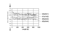
- FIG. 22 shows a comparison of servo band pitches of data bands measured on the same magnetic tape.
- the horizontal axis is the tape length
- the vertical axis is the servo band pitch.
- the servo band pitch on the vertical axis is indicated by the difference with the servo read head pitch P1 (2858.8 ⁇ m) as the reference value (Ref).
- the measurement of the servo band pitch can be performed using the tape drive device 30 as described with reference to FIGS. 12 and 13.
- FIG. 12 and 13 shows a comparison of servo band pitches of data bands measured on the same magnetic tape.
- the horizontal axis is the tape length
- the vertical axis is the servo band pitch.
- the servo band pitch on the vertical axis is indicated by the difference with the servo read head pitch P1 (2858.8 ⁇ m) as the reference value (Ref).
- the measurement of the servo band pitch can be performed using the tape drive device 30 as described with reference to FIGS. 12
- d0 means the interval (servo band pitch s2/s3) between two servo bands s2 and s3 adjacent to data band d0
- d1 means data band d1.
- d2(s3/s4) means the interval between two servo bands s3 and s4 adjacent to data band d2 (servo band pitch s3/s4)
- d3(s0/s1) means It means the interval between two adjacent servo bands s0 and s1 (servo band pitch s0/s1).
- the servo band pitch spreads from data band d3 to d2. is the minimum value
- the maximum amount of change in the servo band pitch represented by the width (absolute value) between the maximum value and the minimum value for the same tape length was approximately 0.13 ⁇ m on average.
- variations in the servo band pitch in each data band may be related to the tension distribution in the width direction of the magnetic tape. For example, due to the deviation in parallelism between the guide rollers 141 and 142 shown in FIG. 21, the tension during servo pattern recording is lower near the data band d3 than the tension during reproduction (the width is narrowed because the tension is applied during reproduction). ), and in the vicinity of the data band d2, it is assumed to have been in a high state (because the tension is loosened during reproduction, the width is widened).
- the tension distribution in the width direction of the magnetic tape is related to the non-uniformity of the strain stress of the magnetic tape and the slight deviation in the parallelism of the guide rollers located upstream and downstream of the servo write head. be done.
- it is difficult to directly measure or grasp the tension distribution in the magnetic tape it is possible to reduce variations in the servo band pitch by grasping and adjusting the parameters that cause changes in the servo band pitch by methods other than tension. It is more preferable to be able to
- the positioning accuracy of the recording/reproducing head for each data band decreases, making it difficult to achieve stable tracking control for each data band.
- the track pitch Wd in which the total number of recording tracks exceeds 6500, not only is the track pitch Wd (see FIG. 4) as small as 1.56 ⁇ m, but the pitch is expected to become narrower in the future. is assumed. Then, it becomes necessary to further improve the positioning accuracy of the recording/reproducing head with respect to the recording track.
- the servo pattern recording apparatus 100 of this embodiment further includes a temperature adjustment section 80 as shown in FIG.
- the temperature adjustment unit 80 is configured to be able to individually raise the temperature of each of the magnetic cores h0 to h4 forming the recording unit 401 of the servo write head 113.
- the temperature adjustment unit 80 is configured as part of the drive unit 120, and based on commands from the controller 130, adjusts the temperature of each recording unit 401 (magnetic cores h0 to h4) of the servo write head 113 within a predetermined temperature range. to adjust individually.
- the temperature adjustment unit 80 can individually adjust the temperature of each recording unit 401 so that the average value of the difference in servo band pitch over the entire length of the tape is equal to or less than a predetermined value (for example, 100 nm or less). configured as possible.
- the temperature adjustment unit 80 has a heating mechanism.
- the heating mechanism includes a power adjuster that can individually adjust the power supplied to the coils 70 of the magnetic cores h0 to h4.
- An amplifier 123 (FIG. 19) for amplifying a pulse signal, which is servo information, to each coil 70 corresponds to this power adjustment section.
- the present inventor focused on the recording current of the servo pattern 6 supplied to the coils 70 of the magnetic cores h0 to h4 of the servo write head 113 (power supplied to the coils 70). It was confirmed that the servo band pitch changed by a little less than 100 nm due to the change in the current value.
- FIG. 23 shows the results of an experiment showing the relationship between the recording current value and the servo band pitch. Similar to FIG. 22, the horizontal axis is the tape length and the vertical axis is the servo band pitch. As shown in the figure, the servo band pitch changes depending on the current value (recording current value) during servo pattern recording.
- the recording current value is the reference value (Ref (1.8 A)) for the tape length of 0 to 200 m, and the recording current value is 20% smaller than the reference value (-20%) for the tape length of 200 m to 400 m. Then, when the tape length is 400 m to 600 m, the recording current value is set to a value 20% larger than the reference value (+20%). was recorded.
- the servo band pitch is narrowed by about 0.05 ⁇ m, and when the recording current value is 20% larger than the reference value, the servo band pitch is 0.05 ⁇ m. confirmed to spread.
- the maximum amount of change in the servo band pitch which is the difference between these maximum and minimum values, was about 100 nm.
- a factor of the change in the servo band pitch is the thermal expansion of the head block 40 of each of the magnetic cores h0 to h4 constituting the servo write head 113 due to Joule heat of the coil 70 . Due to the thermal expansion of the head block 40, the arrangement intervals of the magnetic gaps g between adjacent head blocks 40 change. Therefore, by adjusting the amount of thermal expansion of the head block 40, it is possible to adjust the arrangement interval between the adjacent magnetic gaps g, that is, the servo band pitch, on the order of submicrons.
- the magnetic cores h0 to h4 are made of ferrite material.
- the linear expansion coefficient is 11.7 ⁇ 10 ⁇ 6 [1/° C.], for example, it is calculated that a temperature change of 3° C. results in a dimensional change of 100 nm (11.7 ⁇ 10 ⁇ 6 x 3°C x 2.8588 mm).
- the reference value (Ref) of the recording current was 1.8 A, a temperature change of 7° C. or more was confirmed in the head block 40 of each of the magnetic cores h0 to h4.
- the difference from the result of FIG. 23, in which the maximum amount of change in the servo band pitch is about 100 nm, is presumed to be due to the cooling of the head block 40 due to contact with the running magnetic tape 1 .
- FIG. 24 shows experimental results of the relationship between the magnitude of the recording current, the temperature change of the head block 40, and the running time of the magnetic tape. As shown in FIG. 24, for the same tape running time, the larger the recording current value, the higher the head block temperature rise. Also, the temperature of the head block tends to rise slightly as the tape running time increases.
- the recording current value is a parameter for changes in the servo band pitch.
- data bands d2 and d3 when the servo patterns 6 are recorded in the servo bands s0 and s1 and the servo bands s3 and s4 by varying the magnitude of the recording current were measured.
- the measurement results are shown in FIG.
- the recording current of the servo pattern 6 is alternately set to a value smaller than the reference current value (-20%) and a value higher than the recording current value (+20%) in the tape length range of 200 m, as in the experiment of FIG. Figure 2 shows the change in servo band pitch for data bands d2 and d3 when varied.
- the difference from the experiment in FIG. 23 is that when the recording current values in the servo bands s0 and s1 are -20% of the reference current value, the recording current values in the servo bands s3 and s4 are set to +20% of the reference current value.
- the recording current values in data bands d1 and d4 other than data bands d2 and d3 may be used as reference current values.
- the servo band pitch having the values shown in FIG. 22 is obtained, so that the variation in the servo band pitch between the data bands d2 and d3 can be reduced.
- the magnitude of the recording current may also be optimized for the data bands d1 and d4 in order to further reduce variations in the servo band pitch between the data bands.
- the recording current supplied to the coil 70 of at least one of the magnetic cores h0 to h4 is made larger than the recording current supplied to the coils 70 of the other magnetic cores. For example.
- the tension distribution is such that the tension on the data band d3 side is lower than that on the data band d2 side when the servo pattern 6 is recorded.
- the recording current value of the set of servo bands s3 and s4 sandwiching the data band d2 is made larger than the set of servo bands s0 and s1 sandwiching the data band d3, as shown in FIG.
- the variation in the servo band pitch between the data bands d3 and d2 can be reduced.
- each servo band s is servoed with a constant recording current value (for example, a reference current value) over a predetermined tape length (for example, 200 m or more).
- Pattern 6 is recorded, after which the tape drive apparatus 30 measures the servo band pitch for each recorded data band.
- the recording current value supplied to the coil 70 is optimized.
- the recording current value is set by adjusting the amplification factor of the amplifier 123 of the driving section 120 in the servo pattern recording apparatus 100 . After that, the servo pattern 6 is recorded on each servo band s of the magnetic tape 1 with the adjusted recording current value.
- the temperature adjustment unit 80 may have a cooling mechanism capable of individually cooling the magnetic cores h0 to h4 constituting the recording unit 401 of the servo write head 113 instead of the heating mechanism.
- a cooling mechanism there is a fan unit 90 configured to cool the coils 70 of the magnetic cores h0 to h4 or the head block 40 individually.
- FIG. 26 is a schematic perspective view showing the configuration of the servo write head 110 provided with the blower unit 90.
- FIG. 26 is a schematic perspective view showing the configuration of the servo write head 110 provided with the blower unit 90.
- the blower unit 90 supports both ends of the servo write head 113 in the longitudinal direction (Y′ direction) and the blower block 91 arranged on the side opposite to the recording surface where the magnetic gap g of the servo write head 110 is formed, It has a pair of positioning blocks 92L and 92R for positioning the blower block 91 with respect to the servo write head 113. As shown in FIG.
- the air blowing block 91 is provided with a plurality of gas ejection ports 91a that face the coils 70 of the magnetic cores h0 to h4 in the Z'-axis direction.
- One positioning block 92L of the pair of positioning blocks 92L and 92R is provided with a gas introduction port 92a through which cooling gas can be introduced.
- the gas introduction port 92a communicates with the plurality of gas ejection ports 91a through the interior of the positioning block 92L and the interior of the blower block 92. As shown in FIG. As a result, the coils 70 of the magnetic cores h0 to h4 are cooled by the cooling gas ejected from the gas ejection port 92a.
- the cooling gas is typically air, but gas such as nitrogen may also be used.
- the temperature of the cooling gas is typically room temperature, but it may be a gas cooled below room temperature.
- a nozzle having directivity in the direction of gas ejection may be added to the gas ejection port 92a so that each gas ejection port 92a and each coil 70 correspond to each other.
- the head block 40 A shield plate 93 for shielding from the wind may be arranged around the .
- the blower unit 90 may be configured to uniformly cool the coils 70 of each of the magnetic cores h0 to h4, but the amount of gas ejected to each coil 70 is adjusted so that each of the magnetic cores h0 to h4 has a temperature gradient.
- the blower unit 90 further has a valve mechanism 94 capable of individually adjusting the amount of cooling gas ejected from each gas ejection port 91a.
- the valve mechanism 94 is configured such that the cooling gas introduced from the gas introduction port 92a is individually split and jetted from each gas jetting port 92a, and the jetting amount of the cooling gas can be adjusted for each gas jetting port 91a. be done.
- the adjustment of the cooling gas ejection amount by the valve mechanism 94 is performed by the controller 130 of the servo pattern recording apparatus 100 .
- FIG. 27 shows the result of an experiment showing how the servo pattern pitch changes depending on whether or not cooling gas (air) is introduced. ).
- the servo band pitch between two servo bands s3 and s4 adjacent to data band d2 was measured.
- each magnetic core h0 to h4 has a temperature gradient, thereby controlling the servo for each data band. It is possible to reduce variations in band pitch.
- the flow rate of the cooling gas supplied to the coil 70 of at least one of the magnetic cores h0 to h4 is set higher than the flow rate of the cooling gas supplied to the coils 70 of the other magnetic cores. This includes increasing the
- FIGS. 28 to 30 show the magnetic tape 1 on which the servo pattern 6 is recorded in each servo band by supplying a constant recording current to the coils 70 of the magnetic cores h0 to h4. It is an experimental result showing the maximum value (max) and minimum value (min) of the servo band pitch, which is an interval, and the difference between these maximum and minimum values (servo band pitch difference: SBD).
- FIG. 28 shows experimental results when a servo pattern was recorded without cooling the servo write head 113 with cooling gas
- FIG. 4 shows experimental results when a servo pattern was recorded while
- FIG. 30 shows experimental results when a servo pattern was recorded while cooling the servo write head 113 with cooling gas at a flow rate of 10 L/min.
- the horizontal axis indicates the tape length
- the left vertical axis indicates the amount of change from the reference value (P1: 2858.8 ⁇ m) of the maximum and minimum values of the servo pattern pitch.
- the vertical axis on the right side indicates the difference between the servo pattern pitch and the servo band pitch.
- the thermal expansion of the head block 40 caused by the Joule heat of the coils 70 is suppressed, and the difference in servo band pitch is reduced to 0.1 ⁇ m ( 100 nm) or less.
- the cooling gas flow rate can be optimized in consideration of the difference in the servo band pitch before cooling.
- a servo pattern 6 is recorded on each servo band s over a predetermined tape length (for example, 200 m or more) with a constant recording current value (for example, a reference current value), Thereafter, the tape drive device 30 measures the servo band pitch for each recorded data band. As a result, after confirming the variation in the servo pattern pitch for each data band as shown in FIG. Optimizing the flow rate of the cooling gas supplied to the coil 70 .
- the servo pattern 6 is recorded on each servo band s of the magnetic tape 1 in a state in which the valve mechanism 94 adjusts the ejection amount of the cooling gas from each gas ejection port 92a so as to achieve the set flow rate of the cooling gas. .
- FIG. 31 is a schematic plan view of the servo write head 113A having the plurality of grooves.
- the servo write head 113A has a recording surface 401 for recording servo patterns on the magnetic tape 1 by the magnetic gaps g of the magnetic cores h0 to h4.
- the recording surface 401 has a first region 411 corresponding to the position where the magnetic gap g is provided in the length direction (Y' direction, the width direction of the magnetic tape 1), and the magnetic gap g is provided in the length direction. and a second region 412 corresponding to a position where there is no contact.
- the second region 412 is provided with a plurality of grooves 95 crossing from one end of the width direction (X' direction, the length direction of the magnetic tape 1) perpendicular to the length direction to the other end of the width direction.
- FIG. 32 is an enlarged perspective view showing details of the groove portion 95.
- the plurality of grooves 95 are arranged at intervals in the length direction (Y′-axis direction) of the recording surface 401 and linearly parallel to the width direction (X′-axis direction) of the recording surface 401 .
- the groove portion 95 is formed with a square groove G1 having a flat bottom.
- a flat top T1 is formed between two adjacent square grooves G1.
- the depth of the square groove G1 is about 1 ⁇ m
- the width of the bottom of the square groove G1 is about 5 ⁇ m
- the width (top) of the top T1 is about 5 ⁇ m
- the pitch of the square grooves G1 is about 10 ⁇ m. be done.
- the size of each part is not limited to the above example.
- the width of the bottom of the square grooves G1 can be set between 5 ⁇ m and 20 ⁇ m
- the arrangement pitch of the square grooves G1 can be set between 10 ⁇ m and 25 ⁇ m.
- the servo write head 113A is provided with a plurality of grooves 95 in the second region 412, when the magnetic tape 1 is running, the amount of air flowing through the second region 412 is increased to make the magnetic tape 1 more flexible. It can be levitated from region 412 . As a result, the magnetic tape 1 can be stably brought into contact with the first region 411 having the magnetic gap g, and the magnetic tape 1 can be run almost without contact with the second region 412. The friction with the magnetic tape 1 can be reduced, and the recording accuracy of the servo pattern 7 can be improved.
- the magnetic tape 1 can be floated from the second area 412, temperature rise of the servo write head 113A due to contact frictional heat with the magnetic tape 1 can be suppressed. Furthermore, since the air flowing between the plurality of grooves 95 has a cooling effect on the second region 412, a heat radiation effect from the first region 411 having the magnetic gap g can be obtained. As a result, variations in servo band pitch can be reduced.
- FIG. 33 is a schematic plan view of a servo write head 113B showing a modification of FIG. 31.
- FIG. This servo write head 113B is different from the servo write head 113A in FIG. 31 in that two cutouts 96 are provided in the second region 412 so as to face each other in the width direction (X'-axis direction).
- Each cutout portion 96 is formed by cutting out an end portion in the width direction (X'-axis direction) of the second region 412 in an arc shape.
- the shape of the notch 96 is not limited to an arc shape, and may be rectangular or triangular.
- a plurality of grooves 95 are formed on the surface of the second region 412 so as to be sandwiched between the cutouts 96 in the width direction.
- the second region 412 is narrowed in the width direction by the notch portion 96 .
- the second region 412 is constricted at the center in its length direction (Y'-axis direction). This makes it easier for the air to flow into the second region 412 from the notch portion 96 located upstream in the tape running direction, so that the air can easily pass between the second region 412 and the magnetic tape 1 . Therefore, the magnetic tape 1 can be easily floated from the second area 412, and the cooling effect of the servo write head 113B can be further enhanced.
- the magnetic tape 1 has a long tape shape, and is run in the longitudinal direction during recording and reproduction.
- the surface of the magnetic layer 43 is the surface on which the magnetic head of the recording/reproducing device (not shown) runs.
- the magnetic tape 1 is preferably used in a recording/reproducing apparatus having a ring head as a recording head.
- the magnetic tape 1 is preferably used in a recording/reproducing apparatus capable of recording data with a data track width of 1500 nm or less or 1000 nm or less.
- the substrate 41 is a non-magnetic support that supports the underlying layer 42 and the magnetic layer 43 .
- the base material 41 has a long film shape.
- the upper limit of the average thickness of the base material 41 is preferably 4.2 ⁇ m or less, more preferably 4.0 ⁇ m or less, still more preferably 3.8 ⁇ m or less, and most preferably 3.4 ⁇ m or less.
- the lower limit of the average thickness of the base material 41 is preferably 3 ⁇ m or more, more preferably 3.2 ⁇ m or more. When the lower limit of the average thickness of the base material 41 is 3 ⁇ m or more, a decrease in the strength of the base material 41 can be suppressed.
- the average thickness of the base material 41 is obtained as follows. First, a magnetic tape 1 having a width of 1/2 inch is prepared and cut into a length of 250 mm to prepare a sample. Subsequently, layers other than the base material 41 of the sample (that is, the underlayer 42, the magnetic layer 43 and the back layer 44) are removed with a solvent such as MEK (methyl ethyl ketone) or dilute hydrochloric acid. Next, using a Mitutoyo laser hologram (LGH-110C) as a measuring device, the thickness of the sample (substrate 41) is measured at five or more points, and the measured values are simply averaged (arithmetic average ) to calculate the average thickness of the base material 41 . It is assumed that the measurement position is randomly selected from the sample.
- a Mitutoyo laser hologram LGH-110C
- the base material 41 preferably contains polyester. Since the base material 41 contains polyester, the Young's modulus of the base material 41 in the longitudinal direction can be reduced. Therefore, the width of the magnetic tape 1 can be kept constant or substantially constant by adjusting the tension in the longitudinal direction of the magnetic tape 1 during running with the recording/reproducing device.
- the Young's modulus of the substrate 41 in the longitudinal direction is, for example, 5 GPa or more and 10 GPa or less, preferably 2.5 GPa or more and 7.8 GPa or less, more preferably 3.0 GPa or more and 7.0 GPa or less.
- Polyesters are, for example, polyethylene terephthalate (PET), polyethylene naphthalate (PEN), polybutylene terephthalate (PBT), polybutylene naphthalate (PBN), polycyclohexylene dimethylene terephthalate (PCT), polyethylene-p-oxybenzoate ( PEB) and at least one of polyethylene bisphenoxycarboxylate.
- PET polyethylene terephthalate
- PEN polyethylene naphthalate
- PBT polybutylene terephthalate
- PBN polybutylene naphthalate
- PCT polycyclohexylene dimethylene terephthalate
- PEB polyethylene-p-oxybenzoate
- at least one of the terminal and the side chain of the polyester may be modified.
- polyester in the base material 41 can be confirmed, for example, as follows. First, similar to the method for measuring the average thickness of the base material 41, the magnetic tape 1 is prepared and cut into a length of 250 mm to prepare a sample. Next, an IR spectrum of the sample (base material 41) is obtained by infrared absorption spectrometry (IR). Based on this IR spectrum, it can be confirmed that the base material 41 contains polyester.
- IR infrared absorption spectrometry
- the base material 41 may contain at least one of polyamide, polyetheretherketone, polyimide, polyamideimide, and polyetheretherketone (PEEK), in addition to polyester, and may include polyamide, polyimide, and polyamideimide. , polyolefins, cellulose derivatives, vinyl resins, and other polymeric resins.
- the polyamide may be an aromatic polyamide (aramid).
- the polyimide may be an aromatic polyimide.
- the polyamideimide may be an aromatic polyamideimide.
- the base material 41 when the base material 41 contains polymer resin other than polyester, the base material 41 preferably contains polyester as the main component.
- the main component means the component with the highest content (mass ratio) among the polymer resins contained in the base material 41 .
- the polyester and the polymer resin other than polyester may be mixed or copolymerized.
- the base material 41 may be biaxially stretched in the longitudinal direction and the width direction.
- the polymer resin contained in the base material 41 is preferably oriented obliquely with respect to the width direction of the base material 41 .
- the magnetic layer 43 is a recording layer for recording signals by magnetization patterns.
- the magnetic layer 43 may be a perpendicular recording type recording layer or a longitudinal recording type recording layer.
- the magnetic layer 43 contains, for example, magnetic powder, binder and lubricant.
- the magnetic layer 43 may further contain at least one additive selected from antistatic agents, abrasives, hardeners, rust preventives, non-magnetic reinforcing particles, and the like, if necessary.
- the magnetic layer 43 is not limited to being composed of a coated film of a magnetic material, and may be composed of a sputtered film or vapor-deposited film of a magnetic material.
- the arithmetic mean roughness Ra of the surface of the magnetic layer 43 is 2.0 nm or less, preferably 1.8 nm or less, more preferably 1.6 nm or less. When the arithmetic mean roughness Ra is 2.0 nm or less, it is possible to suppress the decrease in output due to the spacing loss, so excellent electromagnetic conversion characteristics can be obtained.
- the lower limit of the arithmetic mean roughness Ra of the surface of the magnetic layer 43 is preferably 1.0 nm or more, more preferably 1.2 nm or more. When the lower limit of the arithmetic mean roughness Ra of the surface of the magnetic layer 43 is 1.0 nm or more, it is possible to suppress deterioration in running performance due to an increase in friction.
- the arithmetic mean roughness Ra is obtained as follows. First, the surface of the magnetic layer 43 is observed with an AFM (Atomic Force Microscope) to obtain an AFM image of 40 ⁇ m ⁇ 40 ⁇ m.
- the AFM is Nano Scope IIIa D3100 manufactured by Digital Instruments, the cantilever is made of silicon single crystal (Note 1), and the tapping frequency is tuned at 200 to 400 Hz.
- the average height (average surface) Zave ( (Z (1) + Z (2) + ... + Z ( 262, 144))/262, 144).
- the upper limit of the average thickness t m of the magnetic layer 43 is 80 nm or less, preferably 70 nm or less, more preferably 50 nm or less. If the upper limit of the average thickness t m of the magnetic layer 43 is 80 nm or less, the influence of the demagnetizing field can be reduced when a ring-type head is used as the recording head, so that even better electromagnetic conversion characteristics can be obtained. can.
- the lower limit of the average thickness t m of the magnetic layer 43 is preferably 35 nm or more. If the lower limit of the average thickness t m of the magnetic layer 43 is 35 nm or more, the output can be ensured when an MR head is used as the reproducing head, so that even better electromagnetic conversion characteristics can be obtained.
- the average thickness t m of the magnetic layer 43 is obtained as follows. First, the magnetic tape 1 accommodated in the cartridge 10 is unwound, and three samples are prepared by cutting the magnetic tape 1 at three positions of 10 m, 30 m, and 50 m from one end on the outermost circumference side. Subsequently, each sample (the magnetic tape 1 to be measured) is processed by the FIB method or the like to be thinned. When the FIB method is used, a carbon layer and a tungsten layer are formed as protective films as a pretreatment for observing a cross-sectional TEM image, which will be described later.
- the carbon layer is formed on the magnetic layer 43 side surface and the back layer 44 side surface of the magnetic tape 1 by vapor deposition, and the tungsten layer is further formed on the magnetic layer 43 side surface by vapor deposition or sputtering.
- the thinning is performed along the length direction (longitudinal direction) of the magnetic tape 1 . That is, by the thinning, a cross section parallel to both the longitudinal direction and the thickness direction of the magnetic tape 1 is formed.
- TEM transmission electron microscope
- the thickness of the magnetic layer 43 is measured at ten or more positions of each sliced sample.
- the ten measurement positions of each thinned sample are different positions in the longitudinal direction of the magnetic tape 1. randomly selected from.
- the average value obtained by simply averaging (arithmetic mean) the measured values of the obtained thinned samples (the thickness of the magnetic layer 43 at 30 points in total) is defined as the average thickness t m [nm] of the magnetic layer 43. do.
- Magnetic powder includes a plurality of magnetic particles.
- the magnetic particles are, for example, particles containing hexagonal ferrite (hereinafter referred to as “hexagonal ferrite particles”), particles containing epsilon-type iron oxide ( ⁇ iron oxide) (hereinafter referred to as “ ⁇ iron oxide particles”), or Co-containing particles. It is a particle containing spinel ferrite (hereinafter referred to as “cobalt ferrite particle”).
- the magnetic powder is preferably crystal-oriented preferentially in the thickness direction (perpendicular direction) of the magnetic tape 1 .
- the hexagonal ferrite particles have, for example, a plate shape such as a hexagonal plate shape or a columnar shape such as a hexagonal columnar shape (where the thickness or height is smaller than the major axis of the plate surface or bottom surface).
- the hexagonal slope shape includes a substantially hexagonal slope shape.
- the hexagonal ferrite preferably contains at least one of Ba, Sr, Pb and Ca, more preferably at least one of Ba and Sr.
- the hexagonal ferrite may in particular be, for example, barium ferrite or strontium ferrite. Barium ferrite may further contain at least one of Sr, Pb and Ca in addition to Ba.
- the strontium ferrite may further contain at least one of Ba, Pb and Ca in addition to Sr.
- hexagonal ferrite has an average composition represented by the general formula MFe 12 O 19 .
- M is, for example, at least one metal selected from Ba, Sr, Pb and Ca, preferably at least one metal selected from Ba and Sr.
- M may be a combination of Ba and one or more metals selected from the group consisting of Sr, Pb and Ca.
- M may be a combination of Sr and one or more metals selected from the group consisting of Ba, Pb and Ca.
- Part of Fe in the above general formula may be substituted with another metal element.
- the average particle size of the magnetic powder is preferably 13 nm or more and 22 nm or less, more preferably 13 nm or more and 19 nm or less, even more preferably 13 nm or more and 18 nm or less, and particularly preferably 14 nm or more and 17 nm. Below, it is most preferably 14 nm or more and 16 nm or less.
- the average particle size of the magnetic powder is 22 nm or less, even better electromagnetic conversion characteristics (for example, SNR) can be obtained in the high recording density magnetic tape 1 .
- the average particle size of the magnetic powder is 13 nm or more, the dispersibility of the magnetic powder is further improved, and even better electromagnetic conversion characteristics (for example, SNR) can be obtained.
- the average aspect ratio of the magnetic powder is preferably 1.0 or more and 3.0 or less, more preferably 1.5 or more and 2.8 or less, and even more preferably 1.8. 2.7 or less. If the average aspect ratio of the magnetic powder is within the range of 1.0 or more and 3.0 or less, the aggregation of the magnetic powder can be suppressed. In addition, when the magnetic powder is vertically oriented in the process of forming the magnetic layer 43, the resistance applied to the magnetic powder can be suppressed. Therefore, the perpendicular orientation of the magnetic powder can be improved.
- the average particle size and average aspect ratio of the magnetic powder are obtained as follows.
- the magnetic tape 1 to be measured is processed by the FIB method or the like to be thinned.
- a carbon layer and a tungsten layer are formed as protective films as a pretreatment for observing a cross-sectional TEM image, which will be described later.
- the carbon layer is formed on the magnetic layer 43 side surface and the back layer 44 side surface of the magnetic tape 1 by vapor deposition, and the tungsten layer is further formed on the magnetic layer 43 side surface by vapor deposition or sputtering. be.
- the thinning is performed along the length direction (longitudinal direction) of the magnetic tape 1 . That is, by the thinning, a cross section parallel to both the longitudinal direction and the thickness direction of the magnetic tape 1 is formed.
- the cross section of the obtained thin sample was examined with an acceleration voltage of 200 kV and a total magnification of 500,000 times. A cross-sectional observation is performed so that the entirety of 43 is included, and a TEM photograph is taken. The number of TEM photographs is prepared so that 50 particles can be extracted from which the plate diameter DB and plate thickness DA (see FIG. 34) shown below can be measured.
- the particle size of the hexagonal ferrite (hereinafter referred to as "particle size") is defined as the shape of the particles observed in the above TEM photograph, as shown in FIG. , the thickness or height is smaller than the major axis of the plate surface or bottom surface.), the major axis of the plate surface or bottom surface is taken as the value of the plate diameter DB. The thickness or height of the particles observed in the above TEM photograph is taken as the plate thickness DA value.
- the major axis means the longest diagonal distance.
- the thickness or height of the largest grain is defined as the plate thickness DA.
- 50 particles to be extracted from the TEM photograph taken are selected based on the following criteria. Particles partly protruding outside the field of view of the TEM photograph are not measured, but particles with clear contours and present in isolation are measured. When particles overlap, if the boundary between the two particles is clear and the overall shape of the particle can be determined, each particle is measured as a single particle, but the boundary is not clear and the overall shape of the particle cannot be determined Particles that do not have a shape are not measured as the shape of the particles cannot be determined.
- the plate thickness DA of each of the 50 selected particles is measured.
- the average plate thickness DA ave is obtained by simply averaging (arithmetic mean) the plate thicknesses DA thus obtained.
- the average thickness DA ave is the average grain thickness.
- the plate diameter DB of each magnetic powder is measured.
- 50 particles whose tabular diameter DB of the particles can be clearly confirmed are selected from the photographed TEM photographs.
- the plate diameter DB of each of the 50 selected particles is measured.
- a simple average (arithmetic mean) of the plate diameters DB obtained in this way is obtained to obtain an average plate diameter DB ave .
- the average platelet diameter DB ave is the average particle size.
- the average aspect ratio (DB ave /DA ave ) of the particles is obtained from the average plate thickness DA ave and the average plate diameter DB ave .
- the average particle volume of the magnetic powder is preferably 500 nm 3 or more and 2500 nm 3 or less, more preferably 500 nm 3 or more and 1600 nm 3 or less, still more preferably 500 nm 3 or more and 1500 nm 3 or less, especially It is preferably 600 nm 3 or more and 1200 nm 3 or less, and most preferably 600 nm 3 or more and 1000 nm 3 or less.
- the average particle volume of the magnetic powder is 2500 nm 3 or less, the same effects as when the average particle size of the magnetic powder is 22 nm or less can be obtained.
- the average particle volume of the magnetic powder is 500 nm 3 or more, the same effect as when the average particle size of the magnetic powder is 13 nm or more can be obtained.
- the average particle volume of magnetic powder is determined as follows. First, the average major axis length DA ave and the average tabular diameter DB ave are determined as described above for the method of calculating the average particle size of the magnetic powder. Next, the average volume V of the magnetic powder is obtained by the following formula.
- ⁇ iron oxide particles are hard magnetic particles capable of obtaining a high coercive force even when they are fine particles.
- the ⁇ -iron oxide particles have a spherical shape or have a cubic shape.
- the spherical shape shall include substantially spherical shape.
- the cubic shape includes a substantially cubic shape. Since the ⁇ -iron oxide particles have the above-described shape, when the ⁇ -iron oxide particles are used as the magnetic particles, compared to the case where the hexagonal barium ferrite particles are used as the magnetic particles, the magnetic tape 1 It is possible to reduce the contact area between the particles in the thickness direction and suppress the aggregation of the particles. Therefore, it is possible to improve the dispersibility of the magnetic powder and obtain even better electromagnetic conversion characteristics (for example, SNR).
- SNR electromagnetic conversion characteristics
- ⁇ -iron oxide particles have a core-shell structure.
- the ⁇ -iron oxide particles are provided with a core portion and a two-layered shell portion provided around the core portion.
- the shell portion having a two-layer structure may include a first shell portion provided on the core portion and a second shell portion provided on the first shell portion.
- the core portion contains ⁇ -iron oxide.
- the ⁇ -iron oxide contained in the core portion preferably has an ⁇ -Fe 2 O 3 crystal as a main phase, more preferably a single-phase ⁇ -Fe 2 O 3 .
- the first shell part covers at least part of the periphery of the core part.
- the first shell portion may partially cover the periphery of the core portion, or may cover the entire periphery of the core portion. From the viewpoint of ensuring sufficient exchange coupling between the core portion and the first shell portion and improving the magnetic properties, it is preferable that the entire surface of the core portion is covered.
- the first shell part is a so-called soft magnetic layer, and includes a soft magnetic material such as ⁇ -Fe, Ni-Fe alloy or Fe-Si-Al alloy.
- ⁇ -Fe may be obtained by reducing ⁇ -iron oxide contained in the core.
- the second shell portion is an oxide film as an antioxidant layer.
- the second shell portion comprises alpha iron oxide, aluminum oxide or silicon oxide.
- ⁇ -iron oxide includes, for example, at least one iron oxide selected from Fe 3 O 4 , Fe 2 O 3 and FeO.
- the ⁇ -iron oxide may be obtained by oxidizing the ⁇ -Fe contained in the first shell.
- the ⁇ -iron oxide particles have the first shell portion as described above, the coercive force Hc of the core portion alone is maintained at a large value in order to ensure thermal stability, and the ⁇ -iron oxide particles (core-shell particles) as a whole can be adjusted to a coercive force Hc suitable for recording.
- the ⁇ -iron oxide particles have the second shell portion as described above, the ⁇ -iron oxide particles are exposed to the air during and before the manufacturing process of the magnetic tape 1, and the particle surface is rusted. can be suppressed from deteriorating the properties of the ⁇ -iron oxide particles. Therefore, deterioration of the characteristics of the magnetic tape 1 can be suppressed.
- the ⁇ -iron oxide particles may have a shell portion with a single-layer structure.
- the shell portion has the same configuration as the first shell portion.
- the ⁇ -iron oxide particles may contain an additive instead of the core-shell structure, or may have a core-shell structure and contain an additive. In this case, part of the Fe in the ⁇ -iron oxide particles is replaced with the additive.
- the coercive force Hc of the ⁇ -iron oxide particles as a whole can also be adjusted to a coercive force Hc suitable for recording, so that the easiness of recording can be improved.
- the additive is a metal element other than iron, preferably a trivalent metal element, more preferably at least one of Al, Ga and In, still more preferably at least one of Al and Ga.
- the ⁇ -iron oxide containing additives is ⁇ -Fe 2-x M x O 3 crystals.
- the additive is a metal element other than iron, more preferably Al (aluminum), Ga (gallium), In (indium), Co (cobalt), Mn (manganese), Zr (zirconium), Hf (hafnium), Cs ( cesium) and at least one of Ti (titanium), Sm (samarium), Nd (neodymium), Pr (praseodymium) and Tb (terbium).
- the average particle size of the magnetic powder is preferably 10 nm or more and 20 nm or less, more preferably 10 nm or more and 18 nm or less, even more preferably 10 nm or more and 16 nm or less, and particularly preferably 10 nm or more and 15 nm or less. , most preferably 10 nm or more and 14 nm or less.
- a region having a size of 1/2 of the recording wavelength is the actual magnetized region. Therefore, by setting the average particle size of the magnetic powder to half or less of the shortest recording wavelength, even better electromagnetic conversion characteristics (for example, SNR) can be obtained.
- the magnetic tape 1 having a high recording density (for example, the magnetic tape 1 configured to record a signal at the shortest recording wavelength of 40 nm or less) exhibits even better electromagnetic conversion.
- a characteristic eg, SNR
- the average particle size of the magnetic powder is 10 nm or more, the dispersibility of the magnetic powder is further improved, and even better electromagnetic conversion characteristics (for example, SNR) can be obtained.
- the average aspect ratio of the magnetic powder is preferably 1.0 or more and 3.0 or less, more preferably 1.0 or more and 2.5 or less, and even more preferably 1.0 or more. 2.1 or less, particularly preferably 1.0 or more and 1.8 or less. If the average aspect ratio of the magnetic powder is within the range of 1.0 or more and 3.0 or less, the aggregation of the magnetic powder can be suppressed. In addition, when the magnetic powder is vertically oriented in the process of forming the magnetic layer 43, the resistance applied to the magnetic powder can be suppressed. Therefore, the perpendicular orientation of the magnetic powder can be improved.
- the average particle size and average aspect ratio of the magnetic powder are obtained as follows.
- the magnetic tape 1 to be measured is processed by the FIB (Focused Ion Beam) method or the like to be thinned.
- FIB Flucused Ion Beam
- a carbon layer and a tungsten layer are formed as protective layers as a pretreatment for observing a cross-sectional TEM image, which will be described later.
- the carbon layer is formed on the magnetic layer 43 side surface and the back layer 44 side surface of the magnetic tape 1 by vapor deposition, and the tungsten layer is further formed on the magnetic layer 43 side surface by vapor deposition or sputtering. be.
- Thinning is performed along the length direction (longitudinal direction) of the magnetic tape 1 . That is, by the thinning, a cross section parallel to both the longitudinal direction and the thickness direction of the magnetic tape 1 is formed.
- the cross section of the obtained thin sample was examined with an acceleration voltage of 200 kV and a total magnification of 500,000 times. A cross-sectional observation is performed so that the entirety of 43 is included, and a TEM photograph is taken. Next, 50 particles whose shape can be clearly confirmed are selected from the TEM photograph taken, and the major axis length DL and the minor axis length DS of each particle are measured.
- the major axis length DL means the maximum distance (so-called maximum Feret diameter) between two parallel lines drawn from all angles so as to touch the outline of each particle.
- the minor axis length DS means the maximum particle length in the direction orthogonal to the major axis (DL) of the particle.
- the average major axis length DL ave is obtained by simply averaging (arithmetic mean) the major axis lengths DL of the measured 50 particles.
- the average major axis length DL ave obtained in this manner is taken as the average particle size of the magnetic powder.
- the short axis length DS of the measured 50 particles is simply averaged (arithmetic mean) to obtain the average short axis length DS ave .
- the average aspect ratio (DL ave /DS ave ) of the particles is obtained from the average long axis length DL ave and the average short axis length DS ave .
- the average particle volume of the magnetic powder is preferably 500 nm 3 or more and 4000 nm 3 or less, more preferably 500 nm 3 or more and 3000 nm 3 or less, even more preferably 500 nm 3 or more and 2000 nm 3 or less, especially It is preferably 600 nm 3 or more and 1600 nm 3 or less, and most preferably 600 nm 3 or more and 1300 nm 3 or less. Since the noise of the magnetic tape 1 is generally inversely proportional to the square root of the number of particles (i.e., proportional to the square root of the particle volume), a smaller particle volume can provide better electromagnetic conversion characteristics (for example, SNR). can.
- the average particle volume of the magnetic powder is 4000 nm 3 or less, it is possible to obtain even better electromagnetic conversion characteristics (for example, SNR) as in the case where the average particle size of the magnetic powder is 20 nm or less.
- the average particle volume of the magnetic powder is 500 nm 3 or more, the same effect as when the average particle size of the magnetic powder is 10 nm or more can be obtained.
- the average volume of the magnetic powder is obtained as follows.
- the magnetic tape 1 is processed by FIB (Focused Ion Beam) method or the like to be thinned.
- FIB Flucused Ion Beam
- a carbon film and a tungsten thin film are formed as protective films as a pretreatment for observing a cross-sectional TEM image, which will be described later.
- the carbon film is formed on the magnetic layer 43 side surface and the back layer 44 side surface of the magnetic tape 1 by vapor deposition, and the tungsten thin film is further formed on the magnetic layer 43 side surface by vapor deposition or sputtering.
- the thinning is performed along the length direction (longitudinal direction) of the magnetic tape 1 . That is, by the thinning, a cross section parallel to both the longitudinal direction and the thickness direction of the magnetic tape 1 is formed.
- the thin sample thus obtained was examined at an acceleration voltage of 200 kV and a total magnification of 500,000 times. A cross-sectional observation is performed so that it can be seen, and a TEM photograph is obtained. Note that the magnification and the acceleration voltage may be appropriately adjusted according to the type of apparatus.
- 50 particles with a clear particle shape are selected from the TEM photograph taken, and the side length DC of each particle is measured.
- the average side length DC ave is obtained by simply averaging (arithmetic mean) the side lengths DC of the 50 particles measured.
- the cobalt ferrite particles preferably have uniaxial crystal anisotropy. Since the cobalt ferrite particles have uniaxial crystal anisotropy, the magnetic powder can be preferentially crystalline in the thickness direction (perpendicular direction) of the magnetic tape 1 .
- Cobalt ferrite particles have, for example, a cubic shape. In this specification, the cubic shape includes a substantially cubic shape.
- the Co-containing spinel ferrite may further contain at least one of Ni, Mn, Al, Cu and Zn in addition to Co.
- a Co-containing spinel ferrite has, for example, an average composition represented by the following formula.
- CoxMyFe2Oz _ _ _ _ (Wherein, M is, for example, at least one of Ni, Mn, Al, Cu and Zn.
- x is a value within the range of 0.4 ⁇ x ⁇ 1.0
- y is a value within the range of 0 ⁇ y ⁇ 0.3, provided that x and y satisfy the relationship of (x+y) ⁇ 1.0
- z is a value within the range of 3 ⁇ z ⁇ 4.
- a part of Fe may be substituted with another metal element.
- the average particle size of the magnetic powder is preferably 8 nm or more and 16 nm or less, more preferably 8 nm or more and 13 nm or less, and even more preferably 8 nm or more and 10 nm or less.
- the average particle size of the magnetic powder is 16 nm or less, even better electromagnetic conversion characteristics (for example, SNR) can be obtained in the high recording density magnetic tape 1 .
- the average particle size of the magnetic powder is 8 nm or more, the dispersibility of the magnetic powder is further improved, and even better electromagnetic conversion characteristics (for example, SNR) can be obtained.
- the method for calculating the average particle size of the magnetic powder is the same as the method for calculating the average particle size of the magnetic powder when the magnetic powder contains ⁇ -iron oxide particles.
- the average aspect ratio of the magnetic powder is preferably 1.0 or more and 3.0 or less, more preferably 1.0 or more and 2.5 or less, and even more preferably 1.0 or more. 2.1 or less, particularly preferably 1.0 or more and 1.8 or less. If the average aspect ratio of the magnetic powder is within the range of 1.0 or more and 3.0 or less, the aggregation of the magnetic powder can be suppressed. In addition, when the magnetic powder is vertically oriented in the process of forming the magnetic layer 43, the resistance applied to the magnetic powder can be suppressed. Therefore, the perpendicular orientation of the magnetic powder can be improved.
- the method for calculating the average aspect ratio of the magnetic powder is the same as the method for calculating the average aspect ratio of the magnetic powder when the magnetic powder contains ⁇ -iron oxide particles.
- the average particle volume of the magnetic powder is preferably 500 nm 3 or more and 4000 nm 3 or less, more preferably 600 nm 3 or more and 2000 nm 3 or less, and even more preferably 600 nm 3 or more and 1000 nm 3 or less.
- the average particle volume of the magnetic powder is 4000 nm 3 or less, the same effect as when the average particle size of the magnetic powder is 16 nm or less can be obtained.
- the average particle volume of the magnetic powder is 500 nm 3 or more, the same effect as when the average particle size of the magnetic powder is 8 nm or more can be obtained.
- the method for calculating the average particle volume of the magnetic component is the same as the method for calculating the average particle volume when the ⁇ -iron oxide particles have a cubic shape.
- binders include thermoplastic resins, thermosetting resins, and reactive resins.
- thermoplastic resins include vinyl chloride, vinyl acetate, vinyl chloride-vinyl acetate copolymer, vinyl chloride-vinylidene chloride copolymer, vinyl chloride-acrylonitrile copolymer, acrylate-acrylonitrile copolymer, acrylic Acid ester-vinyl chloride-vinylidene chloride copolymer, acrylic acid ester-acrylonitrile copolymer, acrylic acid ester-vinylidene chloride copolymer, methacrylic acid ester-vinylidene chloride copolymer, methacrylic acid ester-vinylidene chloride copolymer , methacrylate ester-ethylene copolymer, polyvinyl fluoride, vinylidene chloride-acrylonitrile copolymer, acrylonitrile-butadiene copolymer, polyamide resin, polyvinyl but
- thermosetting resins examples include phenol resins, epoxy resins, polyurethane curing resins, urea resins, melamine resins, alkyd resins, silicone resins, polyamine resins, and urea-formaldehyde resins.
- R1, R2, and R3 represent a hydrogen atom or a hydrocarbon group
- X- represents a halogen element ion such as fluorine, chlorine, bromine, or iodine, an inorganic ion, or an organic ion.
- -OH, - Polar functional groups such as SH, —CN, and epoxy groups may be introduced.
- the amount of these polar functional groups introduced into the binder is preferably 10 -1 to 10 -8 mol/g, more preferably 10 -2 to 10 -6 mol/g.
- the lubricant contains, for example, at least one selected from fatty acids and fatty acid esters, preferably both fatty acids and fatty acid esters. Containing a lubricant in the magnetic layer 43 , particularly containing both a fatty acid and a fatty acid ester, contributes to improving the running stability of the magnetic tape 1 . More particularly, good running stability is achieved by the magnetic layer 43 containing a lubricant and having pores. The improvement in running stability is considered to be due to the fact that the dynamic friction coefficient of the magnetic layer 43 side surface of the magnetic tape 1 is adjusted to a value suitable for the running of the magnetic tape 1 by the lubricant.
- the fatty acid may preferably be a compound represented by the following general formula (1) or (2).
- the fatty acid may contain one or both of a compound represented by the following general formula (1) and a compound represented by general formula (2).
- the fatty acid ester may preferably be a compound represented by the following general formula (3) or (4).
- a compound represented by the following general formula (3) and a compound represented by general formula (4) may be included as the fatty acid ester.
- the lubricant is one or both of the compound represented by the general formula (1) and the compound represented by the general formula (2), and the compound represented by the general formula (3) and the compound represented by the general formula (4). By including either one or both of, it is possible to suppress an increase in the dynamic friction coefficient due to repeated recording or reproduction of the magnetic tape 1 .
- CH3 ( CH2 ) kCOOH (1) (However, in the general formula (1), k is an integer selected from the range of 14 or more and 22 or less, more preferably 14 or more and 18 or less.)
- Antistatic agents include, for example, carbon black, natural surfactants, nonionic surfactants, cationic surfactants and the like.
- Abrasives include, for example, ⁇ -alumina, ⁇ -alumina, ⁇ -alumina, silicon carbide, chromium oxide, cerium oxide, ⁇ -iron oxide, corundum, silicon nitride, titanium carbide, and oxides with an ⁇ conversion rate of 90% or more. Titanium, silicon dioxide, tin oxide, magnesium oxide, tungsten oxide, zirconium oxide, boron nitride, zinc oxide, calcium carbonate, calcium sulfate, barium sulfate, molybdenum disulfide, and magnetic iron oxide. iron oxides, and those surface-treated with aluminum and/or silica, if necessary, and the like.
- curing agents examples include polyisocyanate and the like.
- polyisocyanates include aromatic polyisocyanates such as adducts of tolylene diisocyanate (TDI) and active hydrogen compounds, and aliphatic polyisocyanates such as adducts of hexamethylene diisocyanate (HMDI) and active hydrogen compounds. mentioned.
- the weight average molecular weight of these polyisocyanates is desirably in the range of 100-3000.
- anti-rust examples include phenols, naphthols, quinones, nitrogen atom-containing heterocyclic compounds, oxygen atom-containing heterocyclic compounds, and sulfur atom-containing heterocyclic compounds.
- Non-magnetic reinforcing particles examples include aluminum oxide ( ⁇ , ⁇ or ⁇ alumina), chromium oxide, silicon oxide, diamond, garnet, emery, boron nitride, titanium carbide, silicon carbide, titanium carbide, titanium oxide (rutile or anatase type titanium oxide) and the like.
- the underlayer 42 is for reducing unevenness on the surface of the base material 41 and adjusting unevenness on the surface of the magnetic layer 43 .
- the underlayer 42 is a non-magnetic layer containing non-magnetic powder, a binder and a lubricant.
- the underlayer 42 supplies lubricant to the surface of the magnetic layer 43 .
- the base layer 42 may further contain at least one additive selected from among an antistatic agent, a curing agent, an antirust agent, and the like, if necessary.
- the average thickness t2 of the underlayer 42 is preferably 0.3 ⁇ m or more and 1.2 ⁇ m or less, more preferably 0.3 ⁇ m or more and 0.9 ⁇ m or less, and 0.3 ⁇ m or more and 0.6 ⁇ m or less.
- the average thickness t 2 of the underlayer 42 is obtained in the same manner as the average thickness t 1 of the magnetic layer 43 .
- the magnification of the TEM image is appropriately adjusted according to the thickness of the underlying layer 42 .
- the average thickness t2 of the underlayer 42 is 1.2 ⁇ m or less, the stretchability of the magnetic tape 1 due to an external force is further increased, so that it is easier to adjust the width of the magnetic tape 1 by adjusting the tension.
- the non-magnetic powder includes, for example, at least one of inorganic powder and organic powder. Also, the non-magnetic powder may contain carbon powder such as carbon black. One type of non-magnetic powder may be used alone, or two or more types of non-magnetic powder may be used in combination.
- Inorganic particles include, for example, metals, metal oxides, metal carbonates, metal sulfates, metal nitrides, metal carbides, metal sulfides, and the like. Examples of the shape of the non-magnetic powder include various shapes such as acicular, spherical, cubic, and plate-like, but are not limited to these shapes.
- binder (binder, lubricant)
- lubricant The binder and lubricant are the same as those for the magnetic layer 43 described above.
- the antistatic agent, curing agent, and antirust agent are the same as those of the magnetic layer 43 described above.
- the back layer 44 contains a binder and non-magnetic powder.
- the back layer 44 may further contain at least one additive such as a lubricant, a curing agent and an antistatic agent, if necessary.
- the binder and non-magnetic powder are the same as those for the underlayer 42 described above.
- the average particle size of the non-magnetic powder is preferably 10 nm or more and 150 nm or less, more preferably 15 nm or more and 110 nm or less.
- the average particle size of the non-magnetic powder is determined in the same manner as the average particle size of the magnetic powder.
- the non-magnetic powder may contain non-magnetic powder having two or more particle size distributions.
- the upper limit of the average thickness of the back layer 44 is preferably 0.6 ⁇ m or less. If the upper limit of the average thickness of the back layer 44 is 0.6 ⁇ m or less, the thickness of the underlayer 42 and the substrate 41 can be kept thick even when the average thickness of the magnetic tape 1 is 5.6 ⁇ m or less. , the running stability of the magnetic tape 1 in the recording/reproducing apparatus can be maintained. Although the lower limit of the average thickness of the back layer 44 is not particularly limited, it is, for example, 0.2 ⁇ m or more.
- the back layer 44 has a surface provided with a large number of protrusions.
- a large number of protrusions are for forming a large number of holes in the surface of the magnetic layer 43 when the magnetic tape 1 is wound into a roll.
- a large number of holes are composed of, for example, a large number of non-magnetic particles protruding from the surface of the back layer 44 .
- the upper limit of the average thickness (average total thickness) t T of the magnetic tape 1 is 5.6 ⁇ m or less, preferably 5.0 ⁇ m or less, more preferably 4.6 ⁇ m or less, and even more preferably 4.4 ⁇ m or less.
- the recording capacity that can be recorded in one data cartridge can be increased as compared with general magnetic tapes.
- the lower limit of the average thickness t T of the magnetic tape 1 is not particularly limited, it is, for example, 3.5 ⁇ m or more.
- the average thickness t T of the magnetic tape 1 is obtained as follows. First, a magnetic tape 1 having a width of 1/2 inch is prepared and cut into a length of 250 mm to prepare a sample. Next, using a Mitutoyo laser hologram (LGH-110C) as a measuring device, the thickness of the sample is measured at 5 or more points, and the measured values are simply averaged (arithmetic average) to obtain an average Calculate the value t T [ ⁇ m]. It is assumed that the measurement position is randomly selected from the sample.
- LGH-110C Mitutoyo laser hologram
- the upper limit of the coercive force Hc2 of the magnetic layer 43 in the longitudinal direction of the magnetic tape 1 is preferably 2000 Oe or less, more preferably 1900 Oe or less, and even more preferably 1800 Oe or less. If the coercive force Hc2 of the magnetic layer 43 in the longitudinal direction is 2000 Oe or less, sufficient electromagnetic conversion characteristics can be obtained even with a high recording density.
- the lower limit of the coercive force Hc2 of the magnetic layer 43 measured in the longitudinal direction of the magnetic tape 1 is preferably 1000 Oe or more.
- the coercive force Hc2 of the magnetic layer 43 measured in the longitudinal direction is 1000 Oe or more, demagnetization due to leakage flux from the recording head can be suppressed.
- the above coercive force Hc2 is obtained as follows. First, unwind the magnetic tape 1 contained in the cartridge, cut the magnetic tape 1 at a position of 30 m from one end of the outermost periphery, and cut the magnetic tape 1 into three pieces with double-sided tape so that the longitudinal direction of the magnetic tape 1 is the same. After being superimposed, they are punched out with a punch of ⁇ 6.39 mm to produce a measurement sample. At this time, marking is performed with any non-magnetic ink so that the longitudinal direction (running direction) of the magnetic tape 1 can be recognized. Then, the MH loop of the measurement sample (entire magnetic tape 1) corresponding to the longitudinal direction (running direction) of the magnetic tape 1 is measured using a vibrating sample magnetometer (VSM).
- VSM vibrating sample magnetometer
- the coating films (underlying layer 42, magnetic layer 43, backing layer 44, etc.) of the magnetic tape 1 cut out above are wiped off with acetone, ethanol, or the like, leaving only the base material 41.
- three sheets of the obtained base material 41 are superimposed with double-sided tape, and then punched out with a punch of ⁇ 6.39 mm to prepare a sample for background correction (hereinafter simply referred to as "correction sample").
- the VSM is used to measure the MH loop of the correction sample (substrate 41) corresponding to the vertical direction of the substrate 41 (perpendicular direction of the magnetic tape 1).
- a high-sensitivity vibrating sample magnetometer manufactured by Toei Kogyo Co., Ltd. -15 type” is used. Measurement conditions are measurement mode: full loop, maximum magnetic field: 15 kOe, magnetic field step: 40 bits, Time constant of locking amp: 0.3 sec, Waiting time: 1 sec, MH average number: 20.
- the MH loop of the measurement sample is corrected.
- the MH loop after background correction is obtained.
- the measurement/analysis program attached to the "VSM-P7-15 type" is used for the calculation of this background correction.
- the coercive force Hc2 is obtained from the obtained MH loop after background correction.
- the measurement/analysis program attached to the "VSM-P7-15 model” is used. It should be noted that the above MH loop measurements are all performed at 25° C. ⁇ 2° C. and 50% RH ⁇ 5% RH. Also, when measuring the MH loop in the longitudinal direction of the magnetic tape 1, "demagnetizing field correction" is not performed.
- the squareness ratio S1 of the magnetic layer 43 in the perpendicular direction (thickness direction) of the magnetic tape 1 is preferably 65% or more, more preferably 70% or more, still more preferably 75% or more, particularly preferably 80% or more, and most preferably. is 85% or more.
- the squareness ratio S1 is 65% or more, the perpendicular orientation of the magnetic powder is sufficiently high, so that even better electromagnetic conversion characteristics (for example, SNR) can be obtained.
- the squareness ratio S1 in the vertical direction is obtained as follows. First, unwind the magnetic tape 1 contained in the cartridge, cut the magnetic tape 1 at a position of 30 m from one end of the outermost periphery, and cut the magnetic tape 1 into three pieces with double-sided tape so that the longitudinal direction of the magnetic tape 1 is the same. After being superimposed, a measurement sample is produced by punching with a punch of ⁇ 6.39 mm. At this time, marking is performed with any non-magnetic ink so that the longitudinal direction (running direction) of the magnetic tape 1 can be recognized. Then, the MH loop of the measurement sample (entire magnetic tape 1) corresponding to the longitudinal direction (running direction) of the magnetic tape 1 is measured using a vibrating sample magnetometer (VSM).
- VSM vibrating sample magnetometer
- the coating films (underlying layer 42, magnetic layer 43, backing layer 44, etc.) of the magnetic tape 1 cut out above are wiped off with acetone, ethanol, or the like, leaving only the base material 41.
- three sheets of the obtained base material 41 are superimposed with double-sided tape, and then punched out with a punch of ⁇ 6.39 mm to prepare a sample for background correction (hereinafter simply referred to as "correction sample").
- the VSM is used to measure the MH loop of the correction sample (substrate 41) corresponding to the vertical direction of the substrate 41 (perpendicular direction of the magnetic tape 1).
- a high-sensitivity vibrating sample magnetometer manufactured by Toei Kogyo Co., Ltd. -15 type” is used. Measurement conditions are measurement mode: full loop, maximum magnetic field: 15 kOe, magnetic field step: 40 bits, Time constant of locking amp: 0.3 sec, Waiting time: 1 sec, MH average number: 20.
- the MH loop of the measurement sample (entire magnetic tape 1) and the MH loop of the correction sample (substrate 41)
- the MH loop of the measurement sample (entire magnetic tape 1) is corrected.
- the MH loop after background correction is obtained.
- the measurement/analysis program attached to the "VSM-P7-15 type" is used for the calculation of this background correction.
- the squareness ratio S2 of the magnetic layer 43 in the longitudinal direction (running direction) of the magnetic tape 1 is preferably 35% or less, more preferably 30% or less, even more preferably 25% or less, particularly preferably 20% or less, most preferably 20% or less. is 15% or less.
- the squareness ratio S2 is 35% or less, the perpendicular orientation of the magnetic powder is sufficiently high, so that even better electromagnetic conversion characteristics (for example, SNR) can be obtained.
- the squareness ratio S2 in the longitudinal direction is obtained in the same manner as the squareness ratio S1, except that the MH loop is measured in the longitudinal direction (running direction) of the magnetic tape 1 and the base material 41.
- the surface roughness of the back surface (the surface roughness of the back layer 44) R b is preferably R b ⁇ 6.0 [nm].
- R b of the back surface is within the above range, even better electromagnetic conversion characteristics can be obtained.
- the azimuth angle inclination (azimuth angle) of the servo frames SF forming the servo pattern 6 is set to 12°. ° or less. Further, although the azimuth angle tilts are of two types, "/" and " ⁇ ", the servo pattern may further include azimuth angle tilts having different tilt angles.
- the blower unit 90 is used as the cooling mechanism, but in addition to this, a thermoelectric element such as a Peltier element may be used.
- a thermoelectric element such as a Peltier element may be used.
- the magnetic tape conforming to the LTO standard has been described as an example of the tape-shaped magnetic recording medium, the present invention is similarly applicable to magnetic tapes of other standards.
- a servo pattern recording apparatus comprising: a temperature adjustment unit configured to be able to individually adjust temperatures of the plurality of recording units.
- the temperature adjusting section individually adjusts the temperatures of the plurality of recording sections so that an average value of differences over the entire length of the tape between two adjacent servo band pitches in the plurality of servo bands is equal to or less than a predetermined value.
- Pattern recorder (3) The servo pattern recording apparatus according to (2) above, The predetermined value is 100 nm.
- Servo pattern recording device The servo pattern recording apparatus according to any one of (1) to (3) above, The servo pattern recording apparatus, wherein the temperature adjustment section has a heating mechanism capable of individually raising the temperature of the plurality of recording sections.
- the servo pattern recording apparatus includes a plurality of magnetic cores having magnetic gaps and a plurality of coils wound around the plurality of magnetic cores,
- the temperature adjustment section has a cooling mechanism capable of individually cooling the plurality of recording sections.
- the servo pattern recording apparatus includes a plurality of magnetic cores having magnetic gaps and a plurality of coils wound around the plurality of magnetic cores, The servo pattern recording apparatus, wherein the cooling mechanism includes a blower unit capable of individually supplying cooling gas to the plurality of coils.
- the servo pattern recording apparatus has a first area corresponding to a position where the magnetic gap is provided in the length direction and a width perpendicular to the length direction corresponding to the position where the magnetic gap is not provided in the length direction. and a recording surface for recording the servo pattern on the magnetic tape by the magnetic gap.
- Device is a first area corresponding to a position where the magnetic gap is provided in the length direction and a width perpendicular to the length direction corresponding to the position where the magnetic gap is not provided in the length direction.
- a method for recording a plurality of servo patterns adjacent in the tape width direction on a magnetic layer of a magnetic tape comprising: running the magnetic tape; Individually adjust the temperature of multiple recording sections of the servo write head, A servo pattern recording method, wherein the plurality of servo patterns are recorded on the magnetic layer by the plurality of recording units.
- the servo pattern recording method according to (9) above The temperature of the plurality of recording portions so that the average value of the difference over the entire length of the tape between the pitches of two adjacent servo bands in the plurality of servo bands of the magnetic layer in which the plurality of servo patterns are recorded is equal to or less than a predetermined value. servo pattern recording method.
- the servo pattern recording method according to (9) or (10) above The plurality of recording units include a plurality of magnetic cores having magnetic gaps and a plurality of coils wound around the plurality of magnetic cores, The servo pattern recording method according to claim 1, wherein the step of adjusting the temperatures of the plurality of recording units makes power supplied to at least one of the plurality of coils greater than power supplied to other coils.
- the servo pattern recording method according to (9) or (10) above,
- the plurality of recording units include a plurality of magnetic cores having magnetic gaps and a plurality of coils wound around the plurality of magnetic cores,
- the servo pattern recording method wherein the step of adjusting the temperatures of the plurality of recording sections supplies cooling gas to at least one of the plurality of coils at a flow rate greater than that of other coils.
- a method for manufacturing a magnetic tape in which a plurality of servo patterns adjacent to each other in the tape width direction are recorded on a magnetic layer of the magnetic tape comprising: running the magnetic tape; Individually adjust the temperature of multiple recording sections of the servo write head, A method of manufacturing a magnetic tape, wherein the plurality of servo patterns are recorded on the magnetic layer by the plurality of recording units.
Landscapes
- Engineering & Computer Science (AREA)
- Manufacturing & Machinery (AREA)
- Adjustment Of The Magnetic Head Position Track Following On Tapes (AREA)
Priority Applications (2)
| Application Number | Priority Date | Filing Date | Title |
|---|---|---|---|
| JP2023546741A JP7790440B2 (ja) | 2021-09-09 | 2022-03-01 | サーボパターン記録装置、サーボパターン記録方法、磁気テープの製造方法、磁気テープ |
| US18/689,358 US12340827B2 (en) | 2021-09-09 | 2022-03-01 | Servo pattern recording apparatus, method of producing a servo pattern recording method, and magnetic tape |
Applications Claiming Priority (2)
| Application Number | Priority Date | Filing Date | Title |
|---|---|---|---|
| JP2021-147168 | 2021-09-09 | ||
| JP2021147168 | 2021-09-09 |
Publications (1)
| Publication Number | Publication Date |
|---|---|
| WO2023037585A1 true WO2023037585A1 (ja) | 2023-03-16 |
Family
ID=85507286
Family Applications (1)
| Application Number | Title | Priority Date | Filing Date |
|---|---|---|---|
| PCT/JP2022/008608 Ceased WO2023037585A1 (ja) | 2021-09-09 | 2022-03-01 | サーボパターン記録装置、サーボパターン記録方法、磁気テープの製造方法、磁気テープ |
Country Status (3)
| Country | Link |
|---|---|
| US (1) | US12340827B2 (https=) |
| JP (1) | JP7790440B2 (https=) |
| WO (1) | WO2023037585A1 (https=) |
Cited By (4)
| Publication number | Priority date | Publication date | Assignee | Title |
|---|---|---|---|---|
| WO2024070554A1 (ja) * | 2022-09-29 | 2024-04-04 | ソニーグループ株式会社 | 磁気記録媒体 |
| US20240185883A1 (en) * | 2021-03-31 | 2024-06-06 | Sony Group Corporation | Magnetic head, servo pattern recording apparatus, tape drive device, method of producing a magnetic tape, and recording method |
| WO2024202790A1 (ja) * | 2023-03-29 | 2024-10-03 | 富士フイルム株式会社 | 磁気テープ、磁気テープカートリッジ、磁気テープシステム、検査方法、及び磁気テープの製造方法 |
| WO2025243789A1 (ja) * | 2024-05-23 | 2025-11-27 | ソニーグループ株式会社 | サーボライトヘッド、サーボパターン記録装置、磁気テープの製造方法及びサーボパターンの記録方法 |
Citations (6)
| Publication number | Priority date | Publication date | Assignee | Title |
|---|---|---|---|---|
| JPS4944727A (https=) * | 1972-08-31 | 1974-04-27 | ||
| JP2003338011A (ja) * | 2002-05-17 | 2003-11-28 | Quantum Corp | 薄膜磁気ヘッド、温度監視およびフィードバックシステム、ならびにテープヘッド |
| JP2009223963A (ja) * | 2008-03-17 | 2009-10-01 | Hitachi Maxell Ltd | 磁気テープ装置 |
| JP2019212354A (ja) * | 2018-06-07 | 2019-12-12 | マクセルホールディングス株式会社 | 熱アシスト記録用塗布型磁気記録媒体及びそれを用いたサーボ信号記録装置 |
| JP2021034078A (ja) * | 2019-08-21 | 2021-03-01 | ソニー株式会社 | 磁気記録媒体、カートリッジおよび記録再生装置 |
| JP2021125271A (ja) * | 2020-01-31 | 2021-08-30 | 富士フイルム株式会社 | 磁気テープカートリッジおよび磁気テープ装置 |
Family Cites Families (19)
| Publication number | Priority date | Publication date | Assignee | Title |
|---|---|---|---|---|
| JPH0726429B2 (ja) | 1990-06-09 | 1995-03-22 | 清友 金武 | 浴槽等の止水装置 |
| US6490117B1 (en) * | 1999-03-26 | 2002-12-03 | Seagate Technology Llc | Method of thermally printing servo patterns on magnetic media |
| JP2005085361A (ja) * | 2003-09-09 | 2005-03-31 | Fuji Photo Film Co Ltd | サーボライタ |
| JP2005285268A (ja) | 2004-03-30 | 2005-10-13 | Sony Corp | リニアテープドライブ装置 |
| US7869154B2 (en) | 2008-03-17 | 2011-01-11 | Hitachi Maxell, Ltd. | Magnetic tape driving apparatus |
| US8000056B2 (en) * | 2009-06-10 | 2011-08-16 | International Business Machines Corporation | Apparatus and method to rotate a read/write head |
| US8270108B2 (en) * | 2009-08-28 | 2012-09-18 | International Business Machines Corporation | Method to minimize the effects of tape skew and tape dimensional stability |
| US9019653B2 (en) * | 2013-08-12 | 2015-04-28 | International Business Machines Corporation | High density timing based servo format for use with tilted transducer arrays |
| JP6694844B2 (ja) * | 2017-03-29 | 2020-05-20 | 富士フイルム株式会社 | 磁気テープ装置、磁気再生方法およびヘッドトラッキングサーボ方法 |
| WO2018199105A1 (ja) * | 2017-04-28 | 2018-11-01 | ソニー株式会社 | 磁気記録媒体 |
| US10332554B1 (en) * | 2018-02-27 | 2019-06-25 | International Business Machines Corporation | Tape drive temperature control for media dimensional stability |
| JP6820881B2 (ja) | 2018-05-28 | 2021-01-27 | 富士フイルム株式会社 | 磁気テープカートリッジ、磁気テープカートリッジの製造方法、磁気テープカートリッジの製造装置、記録再生装置、及び制御方法 |
| US10643647B2 (en) * | 2018-06-29 | 2020-05-05 | Fujifilm Corporation | Magnetic tape apparatus |
| US10460757B1 (en) * | 2018-11-05 | 2019-10-29 | International Business Machines Corporation | Management of head and media dimensional stability |
| JP6610824B1 (ja) * | 2019-04-05 | 2019-11-27 | ソニー株式会社 | カートリッジおよびカートリッジメモリ |
| JP6590105B1 (ja) * | 2019-05-08 | 2019-10-16 | ソニー株式会社 | 磁気記録媒体およびカートリッジ |
| JP7439702B2 (ja) | 2020-02-07 | 2024-02-28 | ソニーグループ株式会社 | カートリッジ |
| JP2023095587A (ja) * | 2021-12-24 | 2023-07-06 | 富士フイルム株式会社 | 磁気テープカートリッジ、磁気テープドライブ、メモリ、磁気テープ、磁気テープシステム、及び磁気テープドライブの動作方法 |
| JP2023147011A (ja) * | 2022-03-29 | 2023-10-12 | 富士フイルム株式会社 | 信号処理装置、磁気テープドライブ、磁気テープ、磁気テープカートリッジ、プログラム、信号処理方法、及び磁気テープ製造方法 |
-
2022
- 2022-03-01 US US18/689,358 patent/US12340827B2/en active Active
- 2022-03-01 JP JP2023546741A patent/JP7790440B2/ja active Active
- 2022-03-01 WO PCT/JP2022/008608 patent/WO2023037585A1/ja not_active Ceased
Patent Citations (6)
| Publication number | Priority date | Publication date | Assignee | Title |
|---|---|---|---|---|
| JPS4944727A (https=) * | 1972-08-31 | 1974-04-27 | ||
| JP2003338011A (ja) * | 2002-05-17 | 2003-11-28 | Quantum Corp | 薄膜磁気ヘッド、温度監視およびフィードバックシステム、ならびにテープヘッド |
| JP2009223963A (ja) * | 2008-03-17 | 2009-10-01 | Hitachi Maxell Ltd | 磁気テープ装置 |
| JP2019212354A (ja) * | 2018-06-07 | 2019-12-12 | マクセルホールディングス株式会社 | 熱アシスト記録用塗布型磁気記録媒体及びそれを用いたサーボ信号記録装置 |
| JP2021034078A (ja) * | 2019-08-21 | 2021-03-01 | ソニー株式会社 | 磁気記録媒体、カートリッジおよび記録再生装置 |
| JP2021125271A (ja) * | 2020-01-31 | 2021-08-30 | 富士フイルム株式会社 | 磁気テープカートリッジおよび磁気テープ装置 |
Cited By (5)
| Publication number | Priority date | Publication date | Assignee | Title |
|---|---|---|---|---|
| US20240185883A1 (en) * | 2021-03-31 | 2024-06-06 | Sony Group Corporation | Magnetic head, servo pattern recording apparatus, tape drive device, method of producing a magnetic tape, and recording method |
| US12406691B2 (en) * | 2021-03-31 | 2025-09-02 | Sony Group Corporation | Magnetic head, servo pattern recording apparatus, tape drive device, method of producing a magnetic tape, and recording method |
| WO2024070554A1 (ja) * | 2022-09-29 | 2024-04-04 | ソニーグループ株式会社 | 磁気記録媒体 |
| WO2024202790A1 (ja) * | 2023-03-29 | 2024-10-03 | 富士フイルム株式会社 | 磁気テープ、磁気テープカートリッジ、磁気テープシステム、検査方法、及び磁気テープの製造方法 |
| WO2025243789A1 (ja) * | 2024-05-23 | 2025-11-27 | ソニーグループ株式会社 | サーボライトヘッド、サーボパターン記録装置、磁気テープの製造方法及びサーボパターンの記録方法 |
Also Published As
| Publication number | Publication date |
|---|---|
| JPWO2023037585A1 (https=) | 2023-03-16 |
| JP7790440B2 (ja) | 2025-12-23 |
| US20240404553A1 (en) | 2024-12-05 |
| US12340827B2 (en) | 2025-06-24 |
Similar Documents
| Publication | Publication Date | Title |
|---|---|---|
| JP7380214B2 (ja) | テープ状磁気記録媒体 | |
| JP6717443B2 (ja) | 磁気記録媒体及びカートリッジ | |
| JP7790440B2 (ja) | サーボパターン記録装置、サーボパターン記録方法、磁気テープの製造方法、磁気テープ | |
| JP2025038207A (ja) | カートリッジ | |
| JP7586266B2 (ja) | 磁気記録媒体 | |
| JP7513145B2 (ja) | データ再生装置 | |
| US20250095678A1 (en) | Servo recording apparatus, servo write head, method of producing a magnetic tape, and magnetic tape | |
| JP7810170B2 (ja) | サーボパターン記録方法、サーボパターン記録装置、磁気テープの製造方法、磁気テープ及びテープカートリッジ | |
| WO2024070554A1 (ja) | 磁気記録媒体 | |
| US12406691B2 (en) | Magnetic head, servo pattern recording apparatus, tape drive device, method of producing a magnetic tape, and recording method | |
| US12136437B2 (en) | Servo pattern recording method, servo pattern recording apparatus, method of producing tape-like magnetic recording medium, tape-like magnetic recording medium, and servo write head | |
| JP6863511B2 (ja) | 磁気記録媒体、カートリッジおよび記録再生装置 | |
| WO2024057947A1 (en) | Magnetic recording medium | |
| JP7327561B2 (ja) | 磁気記録媒体およびカートリッジ | |
| JP6743991B1 (ja) | カートリッジおよび記録再生装置 | |
| WO2024070719A1 (ja) | 磁気記録媒体およびカートリッジ | |
| WO2024090258A1 (ja) | 磁気記録カートリッジ |
Legal Events
| Date | Code | Title | Description |
|---|---|---|---|
| 121 | Ep: the epo has been informed by wipo that ep was designated in this application |
Ref document number: 22866920 Country of ref document: EP Kind code of ref document: A1 |
|
| WWE | Wipo information: entry into national phase |
Ref document number: 2023546741 Country of ref document: JP |
|
| NENP | Non-entry into the national phase |
Ref country code: DE |
|
| 122 | Ep: pct application non-entry in european phase |
Ref document number: 22866920 Country of ref document: EP Kind code of ref document: A1 |
|
| WWG | Wipo information: grant in national office |
Ref document number: 18689358 Country of ref document: US |