WO2022250162A1 - 方向性電磁鋼板の製造方法 - Google Patents
方向性電磁鋼板の製造方法 Download PDFInfo
- Publication number
- WO2022250162A1 WO2022250162A1 PCT/JP2022/021835 JP2022021835W WO2022250162A1 WO 2022250162 A1 WO2022250162 A1 WO 2022250162A1 JP 2022021835 W JP2022021835 W JP 2022021835W WO 2022250162 A1 WO2022250162 A1 WO 2022250162A1
- Authority
- WO
- WIPO (PCT)
- Prior art keywords
- less
- annealing
- grain
- rolling
- steel sheet
- Prior art date
- Legal status (The legal status is an assumption and is not a legal conclusion. Google has not performed a legal analysis and makes no representation as to the accuracy of the status listed.)
- Ceased
Links
Images


Classifications
-
- H—ELECTRICITY
- H01—ELECTRIC ELEMENTS
- H01F—MAGNETS; INDUCTANCES; TRANSFORMERS; SELECTION OF MATERIALS FOR THEIR MAGNETIC PROPERTIES
- H01F1/00—Magnets or magnetic bodies characterised by the magnetic materials therefor; Selection of materials for their magnetic properties
- H01F1/01—Magnets or magnetic bodies characterised by the magnetic materials therefor; Selection of materials for their magnetic properties of inorganic materials
- H01F1/03—Magnets or magnetic bodies characterised by the magnetic materials therefor; Selection of materials for their magnetic properties of inorganic materials characterised by their coercivity
- H01F1/12—Magnets or magnetic bodies characterised by the magnetic materials therefor; Selection of materials for their magnetic properties of inorganic materials characterised by their coercivity of soft-magnetic materials
- H01F1/14—Magnets or magnetic bodies characterised by the magnetic materials therefor; Selection of materials for their magnetic properties of inorganic materials characterised by their coercivity of soft-magnetic materials metals or alloys
- H01F1/147—Alloys characterised by their composition
- H01F1/14766—Fe-Si based alloys
- H01F1/14791—Fe-Si-Al based alloys, e.g. Sendust
-
- C—CHEMISTRY; METALLURGY
- C21—METALLURGY OF IRON
- C21D—MODIFYING THE PHYSICAL STRUCTURE OF FERROUS METALS; GENERAL DEVICES FOR HEAT TREATMENT OF FERROUS OR NON-FERROUS METALS OR ALLOYS; MAKING METAL MALLEABLE, e.g. BY DECARBURISATION OR TEMPERING
- C21D1/00—General methods or devices for heat treatment, e.g. annealing, hardening, quenching or tempering
- C21D1/74—Methods of treatment in inert gas, controlled atmosphere, vacuum or pulverulent material
-
- C—CHEMISTRY; METALLURGY
- C21—METALLURGY OF IRON
- C21D—MODIFYING THE PHYSICAL STRUCTURE OF FERROUS METALS; GENERAL DEVICES FOR HEAT TREATMENT OF FERROUS OR NON-FERROUS METALS OR ALLOYS; MAKING METAL MALLEABLE, e.g. BY DECARBURISATION OR TEMPERING
- C21D1/00—General methods or devices for heat treatment, e.g. annealing, hardening, quenching or tempering
- C21D1/74—Methods of treatment in inert gas, controlled atmosphere, vacuum or pulverulent material
- C21D1/76—Adjusting the composition of the atmosphere
-
- C—CHEMISTRY; METALLURGY
- C21—METALLURGY OF IRON
- C21D—MODIFYING THE PHYSICAL STRUCTURE OF FERROUS METALS; GENERAL DEVICES FOR HEAT TREATMENT OF FERROUS OR NON-FERROUS METALS OR ALLOYS; MAKING METAL MALLEABLE, e.g. BY DECARBURISATION OR TEMPERING
- C21D6/00—Heat treatment of ferrous alloys
- C21D6/001—Heat treatment of ferrous alloys containing Ni
-
- C—CHEMISTRY; METALLURGY
- C21—METALLURGY OF IRON
- C21D—MODIFYING THE PHYSICAL STRUCTURE OF FERROUS METALS; GENERAL DEVICES FOR HEAT TREATMENT OF FERROUS OR NON-FERROUS METALS OR ALLOYS; MAKING METAL MALLEABLE, e.g. BY DECARBURISATION OR TEMPERING
- C21D6/00—Heat treatment of ferrous alloys
- C21D6/002—Heat treatment of ferrous alloys containing Cr
-
- C—CHEMISTRY; METALLURGY
- C21—METALLURGY OF IRON
- C21D—MODIFYING THE PHYSICAL STRUCTURE OF FERROUS METALS; GENERAL DEVICES FOR HEAT TREATMENT OF FERROUS OR NON-FERROUS METALS OR ALLOYS; MAKING METAL MALLEABLE, e.g. BY DECARBURISATION OR TEMPERING
- C21D6/00—Heat treatment of ferrous alloys
- C21D6/005—Heat treatment of ferrous alloys containing Mn
-
- C—CHEMISTRY; METALLURGY
- C21—METALLURGY OF IRON
- C21D—MODIFYING THE PHYSICAL STRUCTURE OF FERROUS METALS; GENERAL DEVICES FOR HEAT TREATMENT OF FERROUS OR NON-FERROUS METALS OR ALLOYS; MAKING METAL MALLEABLE, e.g. BY DECARBURISATION OR TEMPERING
- C21D6/00—Heat treatment of ferrous alloys
- C21D6/007—Heat treatment of ferrous alloys containing Co
-
- C—CHEMISTRY; METALLURGY
- C21—METALLURGY OF IRON
- C21D—MODIFYING THE PHYSICAL STRUCTURE OF FERROUS METALS; GENERAL DEVICES FOR HEAT TREATMENT OF FERROUS OR NON-FERROUS METALS OR ALLOYS; MAKING METAL MALLEABLE, e.g. BY DECARBURISATION OR TEMPERING
- C21D6/00—Heat treatment of ferrous alloys
- C21D6/008—Heat treatment of ferrous alloys containing Si
-
- C—CHEMISTRY; METALLURGY
- C21—METALLURGY OF IRON
- C21D—MODIFYING THE PHYSICAL STRUCTURE OF FERROUS METALS; GENERAL DEVICES FOR HEAT TREATMENT OF FERROUS OR NON-FERROUS METALS OR ALLOYS; MAKING METAL MALLEABLE, e.g. BY DECARBURISATION OR TEMPERING
- C21D8/00—Modifying the physical properties of ferrous metals or ferrous alloys by deformation combined with, or followed by, heat treatment
- C21D8/12—Modifying the physical properties of ferrous metals or ferrous alloys by deformation combined with, or followed by, heat treatment during manufacturing of articles with special electromagnetic properties
- C21D8/1216—Modifying the physical properties of ferrous metals or ferrous alloys by deformation combined with, or followed by, heat treatment during manufacturing of articles with special electromagnetic properties characterised by the working steps
- C21D8/1222—Hot rolling
-
- C—CHEMISTRY; METALLURGY
- C21—METALLURGY OF IRON
- C21D—MODIFYING THE PHYSICAL STRUCTURE OF FERROUS METALS; GENERAL DEVICES FOR HEAT TREATMENT OF FERROUS OR NON-FERROUS METALS OR ALLOYS; MAKING METAL MALLEABLE, e.g. BY DECARBURISATION OR TEMPERING
- C21D8/00—Modifying the physical properties of ferrous metals or ferrous alloys by deformation combined with, or followed by, heat treatment
- C21D8/12—Modifying the physical properties of ferrous metals or ferrous alloys by deformation combined with, or followed by, heat treatment during manufacturing of articles with special electromagnetic properties
- C21D8/1216—Modifying the physical properties of ferrous metals or ferrous alloys by deformation combined with, or followed by, heat treatment during manufacturing of articles with special electromagnetic properties characterised by the working steps
- C21D8/1233—Cold rolling
-
- C—CHEMISTRY; METALLURGY
- C21—METALLURGY OF IRON
- C21D—MODIFYING THE PHYSICAL STRUCTURE OF FERROUS METALS; GENERAL DEVICES FOR HEAT TREATMENT OF FERROUS OR NON-FERROUS METALS OR ALLOYS; MAKING METAL MALLEABLE, e.g. BY DECARBURISATION OR TEMPERING
- C21D8/00—Modifying the physical properties of ferrous metals or ferrous alloys by deformation combined with, or followed by, heat treatment
- C21D8/12—Modifying the physical properties of ferrous metals or ferrous alloys by deformation combined with, or followed by, heat treatment during manufacturing of articles with special electromagnetic properties
- C21D8/1244—Modifying the physical properties of ferrous metals or ferrous alloys by deformation combined with, or followed by, heat treatment during manufacturing of articles with special electromagnetic properties characterised by the heat treatment
- C21D8/1255—Modifying the physical properties of ferrous metals or ferrous alloys by deformation combined with, or followed by, heat treatment during manufacturing of articles with special electromagnetic properties characterised by the heat treatment with diffusion of elements, e.g. decarburising, nitriding
-
- C—CHEMISTRY; METALLURGY
- C21—METALLURGY OF IRON
- C21D—MODIFYING THE PHYSICAL STRUCTURE OF FERROUS METALS; GENERAL DEVICES FOR HEAT TREATMENT OF FERROUS OR NON-FERROUS METALS OR ALLOYS; MAKING METAL MALLEABLE, e.g. BY DECARBURISATION OR TEMPERING
- C21D8/00—Modifying the physical properties of ferrous metals or ferrous alloys by deformation combined with, or followed by, heat treatment
- C21D8/12—Modifying the physical properties of ferrous metals or ferrous alloys by deformation combined with, or followed by, heat treatment during manufacturing of articles with special electromagnetic properties
- C21D8/1244—Modifying the physical properties of ferrous metals or ferrous alloys by deformation combined with, or followed by, heat treatment during manufacturing of articles with special electromagnetic properties characterised by the heat treatment
- C21D8/1261—Modifying the physical properties of ferrous metals or ferrous alloys by deformation combined with, or followed by, heat treatment during manufacturing of articles with special electromagnetic properties characterised by the heat treatment following hot rolling
-
- C—CHEMISTRY; METALLURGY
- C21—METALLURGY OF IRON
- C21D—MODIFYING THE PHYSICAL STRUCTURE OF FERROUS METALS; GENERAL DEVICES FOR HEAT TREATMENT OF FERROUS OR NON-FERROUS METALS OR ALLOYS; MAKING METAL MALLEABLE, e.g. BY DECARBURISATION OR TEMPERING
- C21D8/00—Modifying the physical properties of ferrous metals or ferrous alloys by deformation combined with, or followed by, heat treatment
- C21D8/12—Modifying the physical properties of ferrous metals or ferrous alloys by deformation combined with, or followed by, heat treatment during manufacturing of articles with special electromagnetic properties
- C21D8/1244—Modifying the physical properties of ferrous metals or ferrous alloys by deformation combined with, or followed by, heat treatment during manufacturing of articles with special electromagnetic properties characterised by the heat treatment
- C21D8/1266—Modifying the physical properties of ferrous metals or ferrous alloys by deformation combined with, or followed by, heat treatment during manufacturing of articles with special electromagnetic properties characterised by the heat treatment between cold rolling steps
-
- C—CHEMISTRY; METALLURGY
- C21—METALLURGY OF IRON
- C21D—MODIFYING THE PHYSICAL STRUCTURE OF FERROUS METALS; GENERAL DEVICES FOR HEAT TREATMENT OF FERROUS OR NON-FERROUS METALS OR ALLOYS; MAKING METAL MALLEABLE, e.g. BY DECARBURISATION OR TEMPERING
- C21D8/00—Modifying the physical properties of ferrous metals or ferrous alloys by deformation combined with, or followed by, heat treatment
- C21D8/12—Modifying the physical properties of ferrous metals or ferrous alloys by deformation combined with, or followed by, heat treatment during manufacturing of articles with special electromagnetic properties
- C21D8/1244—Modifying the physical properties of ferrous metals or ferrous alloys by deformation combined with, or followed by, heat treatment during manufacturing of articles with special electromagnetic properties characterised by the heat treatment
- C21D8/1272—Final recrystallisation annealing
-
- C—CHEMISTRY; METALLURGY
- C21—METALLURGY OF IRON
- C21D—MODIFYING THE PHYSICAL STRUCTURE OF FERROUS METALS; GENERAL DEVICES FOR HEAT TREATMENT OF FERROUS OR NON-FERROUS METALS OR ALLOYS; MAKING METAL MALLEABLE, e.g. BY DECARBURISATION OR TEMPERING
- C21D8/00—Modifying the physical properties of ferrous metals or ferrous alloys by deformation combined with, or followed by, heat treatment
- C21D8/12—Modifying the physical properties of ferrous metals or ferrous alloys by deformation combined with, or followed by, heat treatment during manufacturing of articles with special electromagnetic properties
- C21D8/1277—Modifying the physical properties of ferrous metals or ferrous alloys by deformation combined with, or followed by, heat treatment during manufacturing of articles with special electromagnetic properties involving a particular surface treatment
- C21D8/1283—Application of a separating or insulating coating
-
- C—CHEMISTRY; METALLURGY
- C21—METALLURGY OF IRON
- C21D—MODIFYING THE PHYSICAL STRUCTURE OF FERROUS METALS; GENERAL DEVICES FOR HEAT TREATMENT OF FERROUS OR NON-FERROUS METALS OR ALLOYS; MAKING METAL MALLEABLE, e.g. BY DECARBURISATION OR TEMPERING
- C21D9/00—Heat treatment, e.g. annealing, hardening, quenching or tempering, adapted for particular articles; Furnaces therefor
- C21D9/46—Heat treatment, e.g. annealing, hardening, quenching or tempering, adapted for particular articles; Furnaces therefor for sheet metals
-
- C—CHEMISTRY; METALLURGY
- C22—METALLURGY; FERROUS OR NON-FERROUS ALLOYS; TREATMENT OF ALLOYS OR NON-FERROUS METALS
- C22C—ALLOYS
- C22C38/00—Ferrous alloys, e.g. steel alloys
- C22C38/001—Ferrous alloys, e.g. steel alloys containing N
-
- C—CHEMISTRY; METALLURGY
- C22—METALLURGY; FERROUS OR NON-FERROUS ALLOYS; TREATMENT OF ALLOYS OR NON-FERROUS METALS
- C22C—ALLOYS
- C22C38/00—Ferrous alloys, e.g. steel alloys
- C22C38/002—Ferrous alloys, e.g. steel alloys containing In, Mg, or other elements not provided for in one single group C22C38/001 - C22C38/60
-
- C—CHEMISTRY; METALLURGY
- C22—METALLURGY; FERROUS OR NON-FERROUS ALLOYS; TREATMENT OF ALLOYS OR NON-FERROUS METALS
- C22C—ALLOYS
- C22C38/00—Ferrous alloys, e.g. steel alloys
- C22C38/008—Ferrous alloys, e.g. steel alloys containing tin
-
- C—CHEMISTRY; METALLURGY
- C22—METALLURGY; FERROUS OR NON-FERROUS ALLOYS; TREATMENT OF ALLOYS OR NON-FERROUS METALS
- C22C—ALLOYS
- C22C38/00—Ferrous alloys, e.g. steel alloys
- C22C38/02—Ferrous alloys, e.g. steel alloys containing silicon
-
- C—CHEMISTRY; METALLURGY
- C22—METALLURGY; FERROUS OR NON-FERROUS ALLOYS; TREATMENT OF ALLOYS OR NON-FERROUS METALS
- C22C—ALLOYS
- C22C38/00—Ferrous alloys, e.g. steel alloys
- C22C38/04—Ferrous alloys, e.g. steel alloys containing manganese
-
- C—CHEMISTRY; METALLURGY
- C22—METALLURGY; FERROUS OR NON-FERROUS ALLOYS; TREATMENT OF ALLOYS OR NON-FERROUS METALS
- C22C—ALLOYS
- C22C38/00—Ferrous alloys, e.g. steel alloys
- C22C38/06—Ferrous alloys, e.g. steel alloys containing aluminium
-
- C—CHEMISTRY; METALLURGY
- C22—METALLURGY; FERROUS OR NON-FERROUS ALLOYS; TREATMENT OF ALLOYS OR NON-FERROUS METALS
- C22C—ALLOYS
- C22C38/00—Ferrous alloys, e.g. steel alloys
- C22C38/08—Ferrous alloys, e.g. steel alloys containing nickel
-
- C—CHEMISTRY; METALLURGY
- C22—METALLURGY; FERROUS OR NON-FERROUS ALLOYS; TREATMENT OF ALLOYS OR NON-FERROUS METALS
- C22C—ALLOYS
- C22C38/00—Ferrous alloys, e.g. steel alloys
- C22C38/10—Ferrous alloys, e.g. steel alloys containing cobalt
-
- C—CHEMISTRY; METALLURGY
- C22—METALLURGY; FERROUS OR NON-FERROUS ALLOYS; TREATMENT OF ALLOYS OR NON-FERROUS METALS
- C22C—ALLOYS
- C22C38/00—Ferrous alloys, e.g. steel alloys
- C22C38/12—Ferrous alloys, e.g. steel alloys containing tungsten, tantalum, molybdenum, vanadium, or niobium
-
- C—CHEMISTRY; METALLURGY
- C22—METALLURGY; FERROUS OR NON-FERROUS ALLOYS; TREATMENT OF ALLOYS OR NON-FERROUS METALS
- C22C—ALLOYS
- C22C38/00—Ferrous alloys, e.g. steel alloys
- C22C38/14—Ferrous alloys, e.g. steel alloys containing titanium or zirconium
-
- C—CHEMISTRY; METALLURGY
- C22—METALLURGY; FERROUS OR NON-FERROUS ALLOYS; TREATMENT OF ALLOYS OR NON-FERROUS METALS
- C22C—ALLOYS
- C22C38/00—Ferrous alloys, e.g. steel alloys
- C22C38/16—Ferrous alloys, e.g. steel alloys containing copper
-
- C—CHEMISTRY; METALLURGY
- C22—METALLURGY; FERROUS OR NON-FERROUS ALLOYS; TREATMENT OF ALLOYS OR NON-FERROUS METALS
- C22C—ALLOYS
- C22C38/00—Ferrous alloys, e.g. steel alloys
- C22C38/18—Ferrous alloys, e.g. steel alloys containing chromium
- C22C38/20—Ferrous alloys, e.g. steel alloys containing chromium with copper
-
- C—CHEMISTRY; METALLURGY
- C22—METALLURGY; FERROUS OR NON-FERROUS ALLOYS; TREATMENT OF ALLOYS OR NON-FERROUS METALS
- C22C—ALLOYS
- C22C38/00—Ferrous alloys, e.g. steel alloys
- C22C38/18—Ferrous alloys, e.g. steel alloys containing chromium
- C22C38/24—Ferrous alloys, e.g. steel alloys containing chromium with vanadium
-
- C—CHEMISTRY; METALLURGY
- C22—METALLURGY; FERROUS OR NON-FERROUS ALLOYS; TREATMENT OF ALLOYS OR NON-FERROUS METALS
- C22C—ALLOYS
- C22C38/00—Ferrous alloys, e.g. steel alloys
- C22C38/18—Ferrous alloys, e.g. steel alloys containing chromium
- C22C38/26—Ferrous alloys, e.g. steel alloys containing chromium with niobium or tantalum
-
- C—CHEMISTRY; METALLURGY
- C22—METALLURGY; FERROUS OR NON-FERROUS ALLOYS; TREATMENT OF ALLOYS OR NON-FERROUS METALS
- C22C—ALLOYS
- C22C38/00—Ferrous alloys, e.g. steel alloys
- C22C38/18—Ferrous alloys, e.g. steel alloys containing chromium
- C22C38/28—Ferrous alloys, e.g. steel alloys containing chromium with titanium or zirconium
-
- C—CHEMISTRY; METALLURGY
- C22—METALLURGY; FERROUS OR NON-FERROUS ALLOYS; TREATMENT OF ALLOYS OR NON-FERROUS METALS
- C22C—ALLOYS
- C22C38/00—Ferrous alloys, e.g. steel alloys
- C22C38/18—Ferrous alloys, e.g. steel alloys containing chromium
- C22C38/34—Ferrous alloys, e.g. steel alloys containing chromium with more than 1.5% by weight of silicon
-
- C—CHEMISTRY; METALLURGY
- C22—METALLURGY; FERROUS OR NON-FERROUS ALLOYS; TREATMENT OF ALLOYS OR NON-FERROUS METALS
- C22C—ALLOYS
- C22C38/00—Ferrous alloys, e.g. steel alloys
- C22C38/60—Ferrous alloys, e.g. steel alloys containing lead, selenium, tellurium, or antimony, or more than 0.04% by weight of sulfur
-
- H—ELECTRICITY
- H01—ELECTRIC ELEMENTS
- H01F—MAGNETS; INDUCTANCES; TRANSFORMERS; SELECTION OF MATERIALS FOR THEIR MAGNETIC PROPERTIES
- H01F1/00—Magnets or magnetic bodies characterised by the magnetic materials therefor; Selection of materials for their magnetic properties
- H01F1/01—Magnets or magnetic bodies characterised by the magnetic materials therefor; Selection of materials for their magnetic properties of inorganic materials
- H01F1/03—Magnets or magnetic bodies characterised by the magnetic materials therefor; Selection of materials for their magnetic properties of inorganic materials characterised by their coercivity
- H01F1/12—Magnets or magnetic bodies characterised by the magnetic materials therefor; Selection of materials for their magnetic properties of inorganic materials characterised by their coercivity of soft-magnetic materials
- H01F1/14—Magnets or magnetic bodies characterised by the magnetic materials therefor; Selection of materials for their magnetic properties of inorganic materials characterised by their coercivity of soft-magnetic materials metals or alloys
- H01F1/147—Alloys characterised by their composition
-
- H—ELECTRICITY
- H01—ELECTRIC ELEMENTS
- H01F—MAGNETS; INDUCTANCES; TRANSFORMERS; SELECTION OF MATERIALS FOR THEIR MAGNETIC PROPERTIES
- H01F1/00—Magnets or magnetic bodies characterised by the magnetic materials therefor; Selection of materials for their magnetic properties
- H01F1/01—Magnets or magnetic bodies characterised by the magnetic materials therefor; Selection of materials for their magnetic properties of inorganic materials
- H01F1/03—Magnets or magnetic bodies characterised by the magnetic materials therefor; Selection of materials for their magnetic properties of inorganic materials characterised by their coercivity
- H01F1/12—Magnets or magnetic bodies characterised by the magnetic materials therefor; Selection of materials for their magnetic properties of inorganic materials characterised by their coercivity of soft-magnetic materials
- H01F1/14—Magnets or magnetic bodies characterised by the magnetic materials therefor; Selection of materials for their magnetic properties of inorganic materials characterised by their coercivity of soft-magnetic materials metals or alloys
- H01F1/16—Magnets or magnetic bodies characterised by the magnetic materials therefor; Selection of materials for their magnetic properties of inorganic materials characterised by their coercivity of soft-magnetic materials metals or alloys in the form of sheets
-
- C—CHEMISTRY; METALLURGY
- C21—METALLURGY OF IRON
- C21D—MODIFYING THE PHYSICAL STRUCTURE OF FERROUS METALS; GENERAL DEVICES FOR HEAT TREATMENT OF FERROUS OR NON-FERROUS METALS OR ALLOYS; MAKING METAL MALLEABLE, e.g. BY DECARBURISATION OR TEMPERING
- C21D2201/00—Treatment for obtaining particular effects
- C21D2201/05—Grain orientation
-
- C—CHEMISTRY; METALLURGY
- C22—METALLURGY; FERROUS OR NON-FERROUS ALLOYS; TREATMENT OF ALLOYS OR NON-FERROUS METALS
- C22C—ALLOYS
- C22C2202/00—Physical properties
- C22C2202/02—Magnetic
-
- Y—GENERAL TAGGING OF NEW TECHNOLOGICAL DEVELOPMENTS; GENERAL TAGGING OF CROSS-SECTIONAL TECHNOLOGIES SPANNING OVER SEVERAL SECTIONS OF THE IPC; TECHNICAL SUBJECTS COVERED BY FORMER USPC CROSS-REFERENCE ART COLLECTIONS [XRACs] AND DIGESTS
- Y02—TECHNOLOGIES OR APPLICATIONS FOR MITIGATION OR ADAPTATION AGAINST CLIMATE CHANGE
- Y02P—CLIMATE CHANGE MITIGATION TECHNOLOGIES IN THE PRODUCTION OR PROCESSING OF GOODS
- Y02P10/00—Technologies related to metal processing
- Y02P10/20—Recycling
Definitions
- the present invention relates to a method of manufacturing a grain-oriented electrical steel sheet suitable for the iron core material of small transformers that are subjected to rounding.
- Electrical steel sheet is a material widely used as iron cores for transformers and motors. Electrical steel sheets are broadly classified into grain-oriented electrical steel sheets and non-oriented electrical steel sheets.
- the ⁇ 001> orientation which is the axis of easy magnetization of iron, has a texture that is highly aligned in the rolling direction of the steel sheet. It is characteristic that Such a texture is formed by causing secondary recrystallization in the final annealing.
- the secondary recrystallization refers to a phenomenon in which crystal grains of ⁇ 110 ⁇ 001> orientation, so-called Goss orientation, preferentially grow into large grains by utilizing grain boundary energy.
- inhibitors As a representative technique for causing the above secondary recrystallization, there is a technique that utilizes precipitates called inhibitors. For example, a method using AlN and MnS described in Patent Document 1, a method using MnS and MnSe described in Patent Document 2, and the like are known and have been industrially put into practical use. Methods using these inhibitors are useful for stably developing secondary recrystallized grains. In these methods, in order to finely disperse the inhibitor in the steel, it is necessary to heat the slab at a high temperature of 1300° C. or higher to dissolve the inhibitor component once.
- Patent Document 3 and the like disclose a technique for developing Goss-oriented crystal grains by secondary recrystallization in a material that does not contain an inhibitor component. By eliminating impurities such as inhibitor components as much as possible, the dependence of the grain boundary energy on the grain boundary during the primary recrystallization on the grain boundary misorientation angle is revealed, and the Goss orientation can be obtained without using an inhibitor. It is a technique for secondary recrystallization of grains with grains, and its effect is called texture inhibition effect. Since this method does not require fine dispersion of the inhibitor in the steel, it does not require high-temperature slab heating, which was essential, and thus has advantages over the method using the inhibitor in terms of production.
- the present invention has been made in view of such circumstances, and aims to provide a grain-oriented electrical steel sheet that maintains excellent magnetic properties and has good processing accuracy in rounding, and a method for manufacturing the same.
- the inventors of the present invention have extensively studied the conditions of secondary recrystallization in order to solve the above problems, and as a result, succeeded in improving the processing accuracy after rounding by making the secondary recrystallized grains finer. .
- the experiments that have led to the success of the present invention are described below.
- the sheet was cold-rolled to a sheet thickness of 1.7 mm, and at that time, the sheet temperature was controlled by changing the rolling speed and coolant flow rate, and the maximum temperature during cold rolling was variously changed. Further, intermediate annealing was performed at 1050° C. for 100 seconds. After that, the second cold rolling was performed to finish the plate to a thickness of 0.23 mm. At that time, the strip temperature was controlled by changing the rolling speed and coolant flow rate, and the maximum temperature during rolling was variously changed. Further, decarburization annealing is performed at 820°C for 120 seconds, 55% H 2 +45% N 2 , and a dew point of 65°C. It was subjected to final annealing for holding time.
- the atmosphere of the final annealing is an N2 atmosphere during the temperature rise up to 900°C, an H2 atmosphere from 900°C or higher to 1230°C, and an H2 atmosphere until the temperature reaches 1000°C during cooling, and an Ar atmosphere in the subsequent cooling. and
- the average heating rate is 20°C/h from 50°C to 1000°C, the average heating rate is 15°C/h from 1000°C to 1150°C, and the average heating rate is from 1150°C to 1200°C.
- the temperature increase rate was 10°C/h.
- Magnetic flux density B 8 (magnetic flux density at a magnetizing force of 800 A/m) was measured from the obtained steel sheet by the method described in JIS C2550-1 (2011). Also, a 60 mm square sample was cut out from the obtained steel plate and rounded using a twin roll processing machine formed with an iron roll with a diameter of 20 mm and a urethane roll with a diameter of 300 mm. The direction of rolling was the direction perpendicular to the rolling direction (the width direction of the steel sheet). That is, the sample was rounded so that the direction perpendicular to the rolling of the sample drew an arc. The machining accuracy of the sample after rounding thus obtained was evaluated by two parameters H and ⁇ shown in FIG. As shown in FIG.
- H is the distance between the butted sample angles a and b, and .theta. is the angle between the two butted sides A and B.
- the respective parameters are H: 2.0 mm and ⁇ : 0°. The greater the deviation from this value, the poorer the machining accuracy. If each parameter is within the ranges of H: 1.8 to 3.0 mm and ⁇ : 0 to 2.5°, the sample is judged as acceptable. As the evaluation of the machining accuracy in the rounding process, ⁇ was given when both parameters were accepted, ⁇ was given when only one of the parameters was accepted, and x was given when both parameters were rejected.
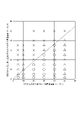
- FIG. 4 shows the relationship between the highest temperatures T1 and T2 of the first and second cold rollings. As shown in FIG. 4, if the highest temperatures T1 and T2 of the first and second cold rolling are in a specific range, that is, a range satisfying 0 ⁇ T1 ⁇ 150, 50 ⁇ T2 ⁇ 400 and T1 ⁇ T2 It was found that both the shape of the rounding process and the magnetic flux density were good.
- the strip temperature was controlled at 70° C. by changing the rolling speed and coolant flow rate.
- intermediate annealing was performed at 1050° C. for 150 seconds, and then cold rolling was performed for the second time to finish the plate to a thickness of 0.23 mm.
- the strip temperature was controlled at 220° C. by changing the rolling speed and coolant flow rate.
- decarburization annealing is performed at 850°C for 120 seconds, 55% H 2 +45% N 2 , and a dew point of 63°C. It was subjected to a final annealing holding under H2 atmosphere for hours.
- the average heating rate was 25°C/h from 50°C to 1000°C, the average heating rate was 16°C/h from 1000°C to 1150°C, and the average heating rate from 1150°C to 1200°C was 16°C/h.
- the temperature increase rate was 10°C/h.
- Magnetic flux density B 8 (magnetic flux density at a magnetizing force of 800 A/m) was measured from the obtained steel sheet by the method described in JIS C2550-1 (2011). Also, a 60 mm square sample was cut out from the obtained steel plate and rounded using a twin roll processing machine formed with an iron roll with a diameter of 20 mm and a urethane roll with a diameter of 300 mm. The direction of rolling was the direction perpendicular to the rolling direction (the width direction of the steel sheet). That is, the sample was rounded so that the direction perpendicular to the rolling of the sample drew an arc. The machining accuracy of the sample after rounding thus obtained was evaluated by two parameters H and ⁇ shown in FIG. As shown in FIG.
- H is the distance between the butted sample angles a and b, and .theta. is the angle between the two butted sides A and B.
- the respective parameters are H: 2.0 mm and ⁇ : 0°. The greater the deviation from this value, the poorer the machining accuracy. If each parameter is within the ranges of H: 1.8 to 3.0 mm and ⁇ : 0 to 2.5°, the sample is judged as acceptable. As the evaluation of the machining accuracy in the rounding process, ⁇ was given when both parameters were accepted, ⁇ was given when only one of the parameters was accepted, and x was given when both parameters were rejected.
- FIG. 5 shows the relationship between the total rolling reduction of the first and second cold rolling. As shown in FIG. 5, when the total rolling reduction R1 of the first cold rolling is 50% or less and the total rolling reduction R2 of the second cold rolling is 50% or more, the shape of rounding and the magnetic flux density was found to be good.
- the strip temperature was controlled at 300° C. by changing the rolling speed and coolant flow rate.
- decarburization annealing is performed at 840° C. ⁇ 80 seconds, 50% H 2 +50% N 2 , dew point 60° C., and after applying an annealing separator containing 90% by mass or more of MgO to the surface of the steel sheet, it is heated at 1200° C. for 10 hours. , was subjected to a final annealing holding under H2 atmosphere.
- the average heating rate H1 from 50°C to 1000°C and the average heating rate H2 from 1000°C to 1150°C were variously changed. From 1150° C. to 1200° C. (maximum temperature reached), the average heating rate was 5° C./h.
- Magnetic flux density B 8 (magnetic flux density at a magnetizing force of 800 A/m) was measured from the obtained steel sheet by the method described in JIS C2550-1 (2011). Also, a 60 mm square sample was cut out from the obtained steel plate and rounded using a twin roll processing machine formed with an iron roll with a diameter of 20 mm and a urethane roll with a diameter of 300 mm. The direction of rolling was the direction perpendicular to the rolling direction (the width direction of the steel sheet). That is, the sample was rounded so that the direction perpendicular to the rolling of the sample drew an arc. The processing accuracy of the rounding samples thus obtained was evaluated in the same manner as in Experiment 1 described above. FIG.
- the average temperature increase rate H1 from 50° C. to 1000° C. is greater than 1.1 times the average temperature increase rate H2 from 1000° C. to 1150° C., and 5° C./h or more to 40° C. /h or less, it was found that the shape of the rounding process is good.
- rounding is a type of plastic working, and is considered to be dependent on crystal orientation. That is, when rounding is performed in one direction, there is a slight misalignment in the orientation of each crystal grain, so the degree of processing of each crystal grain may differ slightly. It is thought that the grain boundaries that allow the accumulation of some strain are what absorb this difference in workability. In other words, when the grain boundaries are few, the grain boundaries cannot absorb the difference in the working degree of each crystal grain, and the steel sheet is distorted, resulting in poor working accuracy. However, when there are many grain boundaries, the difference can be absorbed, so it is considered that the processing accuracy is improved. There are roughly two techniques for reducing the size of secondary grains and increasing grain boundaries.
- the gist and configuration of the present invention are as follows. [1] % by mass, C: 0.010% or more and 0.100% or less, Si: 2.00% or more and 5.00% or less, Mn: 0.01% or more and 0.50% or less, Al: 0.010% or more and 0.040% or less, N: 0.0030% or more and 0.0120% or less and a total of 0.005% or more and 0.100% or less of any one or two of S and Se, the balance being Fe and unavoidable impurities
- a steel material having a chemical composition is heated to a temperature of 1300° C.
- the grain-oriented electrical steel sheet is obtained by applying an annealing separator to the surface of the decarburized annealed sheet and then performing finish annealing to obtain the grain-oriented electrical steel sheet.
- the maximum temperature T1 (°C) in the first cold rolling and the maximum temperature T2 (°C) in the second cold rolling satisfy the following formulas (1) to (3)
- the total rolling reduction R1 (%) in the first cold rolling and the total rolling reduction R2 (%) in the second cold rolling satisfy the following formula (4)
- the average temperature increase rate H1 (° C./h) from 50° C. to 1000° C. and the average temperature increase rate H2 (° C./h) from 1000° C. (maximum attainment temperature ⁇ 50° C.) a method for producing a grain-oriented electrical steel sheet, which satisfies the following formulas (5) and (6).
- the hot rolling after heating the steel material, one pass or more of rough rolling is performed at 1100° C. or more and 1300° C. or less, followed by two passes or more of finish rolling at 800° C. or more and 1100° C. or less,
- the winding temperature is 400° C. or higher and 750° C. or lower
- the hot-rolled sheet annealing the hot-rolled sheet is held at 800° C. or higher and 1250° C. or lower for 5 seconds or longer, and then cooled from 800° C. to 350° C. at an average cooling rate of 5° C./s or higher and 100° C./s or lower. death,
- the intermediate annealing the cold-rolled sheet after the first cold rolling is held at 800° C.
- the cold-rolled sheet is heated to 750° C. or more and 950° C. in an atmosphere containing H 2 and N 2 and in a wet atmosphere having a dew point of 20° C. or more and 80° C. or less in at least a part of the decarburization annealing.
- the annealing separator containing MgO is applied to the surface of the decarburized annealed sheet in an amount of 2.5 g/m 2 or more per side,
- the decarburization-annealed sheet is held at 1050° C. or higher and 1300° C. or lower for 3 hours or more under conditions in which the atmosphere in at least a part of the temperature range of 1050° C. or higher contains H 2 .
- the method for producing a grain-oriented electrical steel sheet according to 1.
- the component composition is further mass % or mass ppm, Ni: 0% or more and 1.50% or less, Cr: 0% or more and 0.50% or less, Cu: 0% or more and 0.50% or less, P: 0% or more and 0.50% or less, Sb: 0% or more and 0.50% or less, Sn: 0% or more and 0.50% or less, Bi: 0% or more and 0.50% or less, Mo: 0% or more and 0.50% or less, B: 0 ppm or more and 25 ppm or less, Nb: 0% or more and 0.020% or less, Manufacture of the grain-oriented electrical steel sheet according to [1] or [2] above, containing at least one selected from V: 0% or more and 0.010% or less and Zr: 0% or more and 0.10% or less Method.
- the component composition further contains, in % by mass, one or two selected from Co: Co: 0% or more and 0.050% or less and Pb: 0% or more and 0.0100% or less.
- the method for producing a grain-oriented electrical steel sheet according to any one of [1] to [3].
- the component composition is further mass %, As: 0% or more and 0.0200% or less, Zn: 0% or more and 0.020% or less, W: 0% or more and 0.0100% or less, Ge: 0%
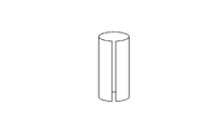
- FIG. 10 is a diagram showing an ideal shape after rounding; It is a figure which shows the shape when processing precision is bad after a rounding process. It is a figure showing the parameter which shows the processing accuracy by rounding processing.
- FIG. 4 is a diagram showing the relationship between the maximum temperature reached during cold rolling and the processing accuracy of rounding.
- FIG. 4 is a diagram showing the relationship between the total rolling reduction of cold rolling and the processing accuracy of rounding.
- FIG. 4 is a diagram showing the relationship between the average heating rate of finish annealing and the processing accuracy of rounding.
- C 0.010% or more and 0.100% or less If C exceeds 0.100%, it becomes difficult to reduce it to 0.005% or less at which magnetic aging does not occur after decarburization annealing. % or less. On the other hand, if the content is less than 0.010%, the grain boundary strengthening effect of C is lost, causing defects such as cracks in the slab that hinder the workability. Therefore, C is limited to 0.010% or more and 0.100% or less. It is preferably 0.025% or more, more preferably 0.035% or more. It is also preferably 0.085% or less, more preferably 0.060% or less.
- Si 2.00% or more and 5.00% or less
- Si is an element necessary for increasing the specific resistance of steel and improving iron loss, but if it is less than 2.00%, there is no effect. On the other hand, if it exceeds 5.00%, the workability of the steel deteriorates and rolling becomes difficult. Therefore, Si is limited to 2.00% or more and 5.00% or less. It is preferably 2.90% or more, more preferably 3.10% or more. It is also preferably 3.70% or less, more preferably 3.55% or less.
- Mn 0.01% or more and 0.50% or less Mn is an element necessary for improving hot workability, but if it is less than 0.01%, there is no effect. On the other hand, if it exceeds 0.50%, the magnetic flux density of the product sheet is lowered. Therefore, Mn should be 0.01% or more and 0.50% or less. It is preferably 0.03% or more, more preferably 0.06% or more. Further, it is preferably 0.25% or less, more preferably 0.15% or less.
- N preferably 0.0039% or more, more preferably N: 0.0050% or more, more preferably N: 0.0113% or less, more preferably N: 0.0100% or less.
- the total content of either one or two of S and Se should be in the range of 0.005% or more and 0.100% or less.
- the total content is preferably 0.010% or more, more preferably 0.020% or more, and preferably 0.055% or less, more preferably 0.040% or less.
- Ni 0% to 1.50%
- Cr 0% to 0.50%
- Cu 0% to 0.50%
- P 0% to 0.50%
- Sb 0% or more and 0.50% or less
- Sn 0% or more and 0.50% or less
- Bi 0% or more and 0.50% or less
- Mo 0% or more and 0.50% or less
- B 0 ppm or more 25 ppm or less
- Nb 0% or more and 0.020% or less
- V 0% or more and 0.010% or less
- Zr 0% or more and 0.10% or less, one selected from alone or two or more Can be added in combination.
- the lower limit amounts are Ni: 0.01% or more, Sb: 0.005% or more, Sn: 0.005% or more, Cu: 0.01% or more, Cr: 0 .01% or more, P: 0.005% or more, Mo: 0.005% or more, Nb: 0.001% or more, V: 0.001% or more, B: 0.0002% or more, Bi: 0.005 % or more and Zr: 0.001% or more.
- One type selected from Co: 0% or more and 0.050% or less and Pb: 0% or more and 0.0100% or less for the purpose of reducing the angle formed by the two butted sides A and B among the rounding workability Or 2 types can be added. If it is less than the above lower limit, the effect of reduction is not exhibited, and if it exceeds the upper limit, there is a concern that the magnetic properties may deteriorate. It is preferable to add at least one selected from Co: 0.002% or more and Pb: 0.0001% or more as the lower limit amount.
- Molten steel having the above components may be produced into slabs by a normal ingot casting method or continuous casting method, or may be produced by direct casting into thin flakes having a thickness of 100 mm or less. These slabs and thin cast pieces as steel materials are hot rolled after being heated by an ordinary method, but hot rolling may be performed immediately after casting without heating.
- As for the above heating temperature in the case of a component system using an inhibitor, it is desirable to heat at 1300° C. or higher to solid-dissolve the inhibitor component.
- one pass or more of rough rolling is performed at 900° C. or more and 1200° C. or less, and then two or more passes of finish rolling are performed at 700° C. or more and 1000° C. or less from the viewpoint of structure control of the hot rolled sheet.
- the temperature conditions and coiling temperature in hot rolling are based on the steel sheet surface temperature immediately before coiling.
- hot-rolled sheet annealing After hot rolling, hot-rolled sheet annealing can be applied as needed.
- the hot-rolled sheet annealing conditions are preferably maintained at 800° C. or higher and 1250° C. or lower for 5 seconds or longer.
- the temperature is maintained at 900° C. or higher and 1150° C. or lower for 10 seconds or longer and 180 seconds or shorter.
- Cooling after holding is preferably at an average cooling rate of 5° C./s or more and 100° C./s or less in the temperature range from 800° C. to 350° C. from the viewpoint of morphology control of the second phase and precipitates. More preferably, it is 15°C/s or more and 45°C/s or less.
- a known method such as a method using heated acid or mechanical scale removal may be used.
- cold rolling is performed two or more times with intermediate annealing to obtain the final plate thickness, and then decarburization annealing is performed.
- the highest temperature T1 (°C) in the first cold rolling and the highest temperature T2 (°C) in the second cold rolling satisfy 0 ⁇ T1 ⁇ 150, 50 ⁇ T2 ⁇ 400, and T1 ⁇ T2.
- the total reduction ratio R1 (%) in the first cold rolling and the total reduction ratio R2 (%) in the second cold rolling satisfy R2 ⁇ 50 ⁇ R1 is essential.
- the highest temperature T1 and the highest temperature T2 are 20°C ⁇ T1 ⁇ 120°C and 100°C ⁇ T2 ⁇ 250°C.
- the total rolling reduction R1 and the total rolling reduction R2 are preferably 20% ⁇ R1 ⁇ 35% and 60% ⁇ R2 ⁇ 92%.
- the maximum temperatures T1 and T2 in cold rolling can be controlled by a method of using heat generated during rolling, a method of heating before rolling, or a method of cooling using a coolant or lubricant. be.
- the temperature conditions and average cooling rate in cold rolling and intermediate annealing are based on the steel sheet surface temperature.
- the temperature In intermediate annealing in cold rolling, it is preferable to hold the temperature in the temperature range of 800°C or higher and 1250°C or lower for 5 seconds or more. That is, if the temperature is lower than 900° C., the recrystallized grains become finer, the number of Goss nuclei in the primary recrystallized structure decreases, and the magnetism may deteriorate. On the other hand, if the temperature exceeds 1250° C., the inhibitor will rapidly grow and decompose, possibly deteriorating the magnetic properties.
- the average cooling rate from 800° C. to 350° C. is preferably 5° C./s or more and 100° C./s or less from the viewpoint of controlling the morphology of the second phase and precipitates.
- the average cooling rate is 15° C./s or more and 45° C./s.
- the steel sheet is preferably degreased to remove the rolling oil from the preceding process. Moreover, after the intermediate annealing, it is preferable to remove the scale on the surface.
- a known method such as a method using a heated acid or mechanical scale removal may be used.
- the steel sheet is subjected to decarburization annealing, but before that, it is preferable to clean the surface of the steel sheet by degreasing and pickling.
- Decarburization annealing is carried out in a temperature range of 750° C. or higher and 950° C. or lower for 10 seconds or more, the atmospheric gas contains H 2 and N 2 , and the dew point is 20° C. or higher in part or all of the decarburization annealing. A wet atmosphere of 80° C. or less is preferable. More preferably, the decarburization annealing conditions are a temperature range of 800°C or higher and 900°C or lower and a dew point of 40°C or higher and 70°C or lower. In addition, the temperature condition in decarburization annealing is based on the steel plate surface temperature.
- the first half of decarburization annealing is performed in a moist atmosphere with the above-mentioned temperature range and dew point conditions
- the second half of decarburization annealing is performed in a temperature range of 800 ° C. or higher and 900 ° C. or lower with a dew point of -50 ° C. or higher and 30 ° C. or lower. It is preferable to perform the annealing in a dry atmosphere because the subscales of the extreme surface layer are reduced and the formation of the forsterite film in the final annealing is advantageous.
- a known annealing separator can be used as the annealing separator.
- "mainly composed of MgO” means that the content of MgO in the annealing separator is 60% or more in terms of solid content.
- the content of MgO in the annealing separator is preferably 80% or more in terms of solid content.
- the method of applying the annealing separator to the surface of the decarburized annealed sheet is not particularly limited, and any known method may be used.
- the annealing separator may be applied in the form of a slurry to the surface of the decarburized annealed plate, or dry applied by electrostatic coating.
- the slurry-like annealing separator is preferably kept at a constant temperature of 5° C. or higher and 30° C. or lower in order to suppress an increase in viscosity.
- the coil is annealed in the up-end condition because the finish anneal takes a long time. Therefore, it is preferable to prevent the outer winding of the up-end coil from unwinding by winding a band or the like around the coil before the finish annealing.
- the average temperature increase rate H1 (° C./h) from 50° C. to 1000° C. and the average temperature from 1000° C. It is essential that the heating rate H2 (°C/h) satisfy H1 ⁇ 1.1 ⁇ H2 and 5 ⁇ H1 ⁇ 40. Preferably, H1 ⁇ 1.2 ⁇ H2 and 10 ⁇ H1 ⁇ 30.
- the temperature conditions and average heating rate in the final annealing are based on the steel sheet temperature at the intermediate position between the inner and outer turns of the surface where the up-end steel sheet coil contacts the floor of the annealing furnace.
- the temperature is held at a temperature of 1100° C. or more and 1300° C. or less for 3 hours or more, and the temperature is within the temperature range of 1000° C. or more. It is preferable to introduce an atmosphere containing H 2 in part or all of the . It is preferable that the final annealing reaches a maximum temperature of 1150° C. or more and 1300° C. or less. After finish annealing, it is useful to wash with water, brush, or pickle in order to remove the attached annealing separator. After that, performing flattening annealing to correct the shape is effective for reducing iron loss.
- the coating is preferably a coating capable of imparting tension to the steel sheet to reduce iron loss.
- a coating liquid may be applied before flattening annealing, and baking may be performed by flattening annealing.
- a tension coating application method using a binder or a coating method in which inorganic substances are vapor-deposited on the steel sheet surface layer by physical vapor deposition or chemical vapor deposition is adopted, coating adhesion is excellent and iron loss is significantly reduced. preferable.
- a steel slab having a chemical composition containing 0055% and the balance being Fe and unavoidable impurities is reheated at a temperature of 1430 ° C., subjected to 6 passes of rough rolling from 1200 ° C., and 9 passes of finish rolling from 1100 ° C.
- Hot-rolled sheets with various thicknesses from 0.85 mm to 2.70 mm were produced by hot rolling performed at . The winding temperature was 575°C.
- the hot-rolled sheet was annealed at 1000° C.
- Table 1 shows the rolling reduction R1 in the first cold rolling.
- the strip temperature was controlled by changing the rolling speed and the coolant flow rate, and the maximum temperature T1 was variously changed as shown in Table 1.
- intermediate annealing was performed at 1050° C. for 100 seconds.
- the average cooling rate in the intermediate annealing temperature range from 800°C to 350°C was 25°C/s.
- the second cold rolling was performed to finish the sheet to a thickness of 0.23 mm.
- Table 1 shows the reduction ratio R2 at this time. At that time, the strip temperature was controlled by changing the rolling speed and the coolant flow rate, and the maximum temperature T2 was variously changed as shown in Table 1.
- the cold-rolled sheet is decarburized and annealed at 820° C. for 120 seconds in 55% H 2 +45% N 2 with a dew point of 65° C., and after coating the surface of the steel sheet with an annealing separator containing 90% by mass or more of MgO. , was subjected to final annealing at 1200° C. for 5 hours.
- the atmosphere of the final annealing is an N2 atmosphere during the temperature rise up to 900°C, an H2 atmosphere from 900°C or higher to 1200°C, and an H2 atmosphere until the cooling temperature reaches 1000°C, and an Ar atmosphere in the subsequent cooling. did.
- the average heating rate H1 from 50°C to 1000°C and the average heating rate H2 from 1000°C to 1150°C were variously changed as shown in Table 1, and the temperature was changed from 1150°C to 1200°C.
- the average heating rate was 10° C./h up to.
- the magnetic flux density B8 of the thus obtained grain-oriented electrical steel sheet was evaluated according to JIS C2550-1 (2011). The results are also shown in Table 1. Magnetic flux density of 1.900 T or more was judged to be excellent in magnetic properties. Also, a 60 mm square sample was cut out from the obtained steel plate and rounded using a twin roll processing machine formed with an iron roll with a diameter of 20 mm and a urethane roll with a diameter of 300 mm. The direction of rolling was the direction perpendicular to the rolling direction (the width direction of the steel sheet). That is, the sample was rounded so that the direction perpendicular to the rolling of the sample drew an arc. The machining accuracy of the sample after rounding thus obtained was evaluated using the two parameters H and ⁇ shown in FIG.
- the sheet thickness was reduced to 1.6 mm by the first cold rolling (reduction rate R1: 33.3%), and the coolant flow rate was controlled so that the highest rolling temperature T1 was 50°C.
- intermediate annealing was performed at 1050° C. for 100 seconds, and the average cooling rate in the intermediate annealing temperature range from 800° C. to 350° C. was 40° C./s.
- it was finished to a thickness of 0.23 mm by cold rolling for the second time (reduction rate R2: 85.6%).
- the rolling speed and the coolant flow rate were controlled, and the highest temperature T2 of rolling was set to 220°C.
- T1, T2, R1 and R2 satisfy formulas (1) to (4).
- the cold-rolled sheet was further subjected to the former stage at 820°C for 120 seconds, 55% H 2 +45% N 2 , dew point of 65°C, and the latter stage at 840°C for 30 seconds, 55% H 2 + 45% N 2 , dew point.
- Decarburization annealing was performed at 15°C.
- the surface of the steel sheet was coated with an annealing separator containing 85% by mass or more of MgO, and then subjected to final annealing at 1200° C. for 12 hours.
- the atmosphere of the final annealing was N2 atmosphere during temperature rise up to 900°C, H2 atmosphere from 900°C to 1200°C, and Ar atmosphere for subsequent cooling.
- the average heating rate H1 from 50°C to 1000°C was 28°C/h, from 1000°C to 1150°C was 18°C/h, from 1150°C to 1200°C was The average heating rate was 8°C/h.
- H1 and H2 satisfy equations (5)-(6).
- the magnetic flux density B8 of the thus obtained grain-oriented electrical steel sheet was evaluated according to JIS C2550-1 (2011). The results are also shown in Table 2. Magnetic flux density of 1.900 T or more was judged to be excellent in magnetic properties. Also, a 60 mm square sample was cut out from the obtained steel plate and rounded using a twin roll processing machine formed with an iron roll with a diameter of 20 mm and a urethane roll with a diameter of 300 mm. The direction of rolling was the direction perpendicular to the rolling direction (the width direction of the steel sheet). That is, the sample was rounded so that the direction perpendicular to the rolling of the sample drew an arc. The machining accuracy of the sample after rounding thus obtained was evaluated using the two parameters H and ⁇ shown in FIG.
Landscapes
- Chemical & Material Sciences (AREA)
- Engineering & Computer Science (AREA)
- Materials Engineering (AREA)
- Mechanical Engineering (AREA)
- Metallurgy (AREA)
- Organic Chemistry (AREA)
- Physics & Mathematics (AREA)
- Thermal Sciences (AREA)
- Crystallography & Structural Chemistry (AREA)
- Electromagnetism (AREA)
- Manufacturing & Machinery (AREA)
- Dispersion Chemistry (AREA)
- Power Engineering (AREA)
- Manufacturing Of Steel Electrode Plates (AREA)
- Soft Magnetic Materials (AREA)
Priority Applications (5)
| Application Number | Priority Date | Filing Date | Title |
|---|---|---|---|
| KR1020237042449A KR20240006635A (ko) | 2021-05-28 | 2022-05-27 | 방향성 전기 강판의 제조 방법 |
| CN202280038074.7A CN117396618A (zh) | 2021-05-28 | 2022-05-27 | 取向性电磁钢板的制造方法 |
| US18/561,412 US20240249863A1 (en) | 2021-05-28 | 2022-05-27 | Method of producing grain-oriented electrical steel sheet |
| JP2022572796A JP7517472B2 (ja) | 2021-05-28 | 2022-05-27 | 方向性電磁鋼板の製造方法 |
| EP22811430.2A EP4335938A4 (en) | 2021-05-28 | 2022-05-27 | PROCESS FOR PRODUCING GRAIN-ORIENTED ELECTROMAGNETIC STEEL SHEET |
Applications Claiming Priority (2)
| Application Number | Priority Date | Filing Date | Title |
|---|---|---|---|
| JP2021090686 | 2021-05-28 | ||
| JP2021-090686 | 2021-05-28 |
Publications (1)
| Publication Number | Publication Date |
|---|---|
| WO2022250162A1 true WO2022250162A1 (ja) | 2022-12-01 |
Family
ID=84228386
Family Applications (1)
| Application Number | Title | Priority Date | Filing Date |
|---|---|---|---|
| PCT/JP2022/021835 Ceased WO2022250162A1 (ja) | 2021-05-28 | 2022-05-27 | 方向性電磁鋼板の製造方法 |
Country Status (6)
| Country | Link |
|---|---|
| US (1) | US20240249863A1 (https=) |
| EP (1) | EP4335938A4 (https=) |
| JP (1) | JP7517472B2 (https=) |
| KR (1) | KR20240006635A (https=) |
| CN (1) | CN117396618A (https=) |
| WO (1) | WO2022250162A1 (https=) |
Cited By (3)
| Publication number | Priority date | Publication date | Assignee | Title |
|---|---|---|---|---|
| JP7772288B1 (ja) * | 2024-05-14 | 2025-11-18 | Jfeスチール株式会社 | 方向性電磁鋼板の製造方法 |
| WO2025239047A1 (ja) * | 2024-05-14 | 2025-11-20 | Jfeスチール株式会社 | 方向性電磁鋼板の製造方法 |
| EP4621080A4 (en) * | 2023-02-01 | 2026-03-04 | Jfe Steel Corp | METHOD FOR PRODUCING A CORN-ORIENTED ELECTRIC STEEL SHEET |
Citations (11)
| Publication number | Priority date | Publication date | Assignee | Title |
|---|---|---|---|---|
| JPS4015644B1 (https=) | 1963-04-05 | 1965-07-21 | ||
| JPS5113469B2 (https=) | 1972-10-13 | 1976-04-28 | ||
| JPH08277421A (ja) * | 1995-04-07 | 1996-10-22 | Nippon Steel Corp | 磁気特性と被膜性状の優れた一方向性電磁鋼板の製造方法 |
| JP2000129356A (ja) | 1998-10-28 | 2000-05-09 | Kawasaki Steel Corp | 方向性電磁鋼板の製造方法 |
| JP2001049351A (ja) * | 1999-08-11 | 2001-02-20 | Nippon Steel Corp | 磁束密度の高い一方向性電磁鋼板の製造方法 |
| JP2006274405A (ja) * | 2005-03-30 | 2006-10-12 | Jfe Steel Kk | 高磁束密度方向性電磁鋼板の製造方法 |
| JP2007262436A (ja) * | 2006-03-27 | 2007-10-11 | Jfe Steel Kk | 方向性電磁鋼板の製造方法 |
| JP2008156693A (ja) * | 2006-12-22 | 2008-07-10 | Nippon Steel Corp | 良好な皮膜を有する磁気特性の優れた方向性電磁鋼板の製造方法 |
| JP2013139629A (ja) * | 2011-12-06 | 2013-07-18 | Jfe Steel Corp | 低鉄損方向性電磁鋼板の製造方法 |
| WO2019146694A1 (ja) * | 2018-01-25 | 2019-08-01 | 日本製鉄株式会社 | 方向性電磁鋼板 |
| WO2020149347A1 (ja) * | 2019-01-16 | 2020-07-23 | 日本製鉄株式会社 | 方向性電磁鋼板の製造方法 |
Family Cites Families (4)
| Publication number | Priority date | Publication date | Assignee | Title |
|---|---|---|---|---|
| JPH05113469A (ja) | 1991-10-22 | 1993-05-07 | Seiko Epson Corp | 半導体装置 |
| US5885371A (en) * | 1996-10-11 | 1999-03-23 | Kawasaki Steel Corporation | Method of producing grain-oriented magnetic steel sheet |
| KR100440994B1 (ko) * | 1996-10-21 | 2004-10-21 | 제이에프이 스틸 가부시키가이샤 | 방향성전자강판및그제조방법 |
| JP4015644B2 (ja) | 2004-05-31 | 2007-11-28 | 株式会社ソニー・コンピュータエンタテインメント | 画像処理装置及び画像処理方法 |
-
2022
- 2022-05-27 CN CN202280038074.7A patent/CN117396618A/zh active Pending
- 2022-05-27 US US18/561,412 patent/US20240249863A1/en active Pending
- 2022-05-27 JP JP2022572796A patent/JP7517472B2/ja active Active
- 2022-05-27 WO PCT/JP2022/021835 patent/WO2022250162A1/ja not_active Ceased
- 2022-05-27 EP EP22811430.2A patent/EP4335938A4/en active Pending
- 2022-05-27 KR KR1020237042449A patent/KR20240006635A/ko active Pending
Patent Citations (11)
| Publication number | Priority date | Publication date | Assignee | Title |
|---|---|---|---|---|
| JPS4015644B1 (https=) | 1963-04-05 | 1965-07-21 | ||
| JPS5113469B2 (https=) | 1972-10-13 | 1976-04-28 | ||
| JPH08277421A (ja) * | 1995-04-07 | 1996-10-22 | Nippon Steel Corp | 磁気特性と被膜性状の優れた一方向性電磁鋼板の製造方法 |
| JP2000129356A (ja) | 1998-10-28 | 2000-05-09 | Kawasaki Steel Corp | 方向性電磁鋼板の製造方法 |
| JP2001049351A (ja) * | 1999-08-11 | 2001-02-20 | Nippon Steel Corp | 磁束密度の高い一方向性電磁鋼板の製造方法 |
| JP2006274405A (ja) * | 2005-03-30 | 2006-10-12 | Jfe Steel Kk | 高磁束密度方向性電磁鋼板の製造方法 |
| JP2007262436A (ja) * | 2006-03-27 | 2007-10-11 | Jfe Steel Kk | 方向性電磁鋼板の製造方法 |
| JP2008156693A (ja) * | 2006-12-22 | 2008-07-10 | Nippon Steel Corp | 良好な皮膜を有する磁気特性の優れた方向性電磁鋼板の製造方法 |
| JP2013139629A (ja) * | 2011-12-06 | 2013-07-18 | Jfe Steel Corp | 低鉄損方向性電磁鋼板の製造方法 |
| WO2019146694A1 (ja) * | 2018-01-25 | 2019-08-01 | 日本製鉄株式会社 | 方向性電磁鋼板 |
| WO2020149347A1 (ja) * | 2019-01-16 | 2020-07-23 | 日本製鉄株式会社 | 方向性電磁鋼板の製造方法 |
Cited By (3)
| Publication number | Priority date | Publication date | Assignee | Title |
|---|---|---|---|---|
| EP4621080A4 (en) * | 2023-02-01 | 2026-03-04 | Jfe Steel Corp | METHOD FOR PRODUCING A CORN-ORIENTED ELECTRIC STEEL SHEET |
| JP7772288B1 (ja) * | 2024-05-14 | 2025-11-18 | Jfeスチール株式会社 | 方向性電磁鋼板の製造方法 |
| WO2025239047A1 (ja) * | 2024-05-14 | 2025-11-20 | Jfeスチール株式会社 | 方向性電磁鋼板の製造方法 |
Also Published As
| Publication number | Publication date |
|---|---|
| JPWO2022250162A1 (https=) | 2022-12-01 |
| US20240249863A1 (en) | 2024-07-25 |
| KR20240006635A (ko) | 2024-01-15 |
| CN117396618A (zh) | 2024-01-12 |
| EP4335938A1 (en) | 2024-03-13 |
| EP4335938A4 (en) | 2024-10-30 |
| JP7517472B2 (ja) | 2024-07-17 |
Similar Documents
| Publication | Publication Date | Title |
|---|---|---|
| JP5988026B2 (ja) | 方向性電磁鋼板の製造方法 | |
| JP7517472B2 (ja) | 方向性電磁鋼板の製造方法 | |
| US20170240988A1 (en) | Method of manufacturing grain-oriented electrical steel sheet | |
| WO2014132354A1 (ja) | 方向性電磁鋼板の製造方法 | |
| JP7338812B1 (ja) | 方向性電磁鋼板の製造方法 | |
| CN102197149A (zh) | 方向性电磁钢板的制造方法 | |
| JP7197068B1 (ja) | 方向性電磁鋼板の製造方法 | |
| JP4962516B2 (ja) | 方向性電磁鋼板の製造方法 | |
| JP7226678B1 (ja) | 方向性電磁鋼板の製造方法 | |
| JP7439943B2 (ja) | 方向性電磁鋼板の製造方法 | |
| JP4811390B2 (ja) | 二方向性電磁鋼板 | |
| EP2243865B1 (en) | Grain-oriented electromagnetic steel sheet excellent in magnetic characteristics | |
| JP6866901B2 (ja) | 方向性電磁鋼板の製造方法 | |
| JP7287584B2 (ja) | 方向性電磁鋼板の製造方法 | |
| JP5712626B2 (ja) | 方向性電磁鋼板の製造方法 | |
| KR20230159874A (ko) | 방향성 전자 강판의 제조 방법 | |
| JP7255761B1 (ja) | 方向性電磁鋼板の製造方法 | |
| JP7264322B1 (ja) | 方向性電磁鋼板の製造方法 | |
| JP7800777B2 (ja) | 方向性電磁鋼板 | |
| JP7226677B1 (ja) | 方向性電磁鋼板の製造方法 | |
| JP7537505B2 (ja) | 方向性電磁鋼板の製造方法 | |
| JP2011111653A (ja) | 方向性電磁鋼板の製造方法 | |
| WO2022250160A1 (ja) | 方向性電磁鋼板の製造方法 |
Legal Events
| Date | Code | Title | Description |
|---|---|---|---|
| ENP | Entry into the national phase |
Ref document number: 2022572796 Country of ref document: JP Kind code of ref document: A |
|
| 121 | Ep: the epo has been informed by wipo that ep was designated in this application |
Ref document number: 22811430 Country of ref document: EP Kind code of ref document: A1 |
|
| WWE | Wipo information: entry into national phase |
Ref document number: 202317077899 Country of ref document: IN Ref document number: 18561412 Country of ref document: US |
|
| WWE | Wipo information: entry into national phase |
Ref document number: 202280038074.7 Country of ref document: CN |
|
| ENP | Entry into the national phase |
Ref document number: 20237042449 Country of ref document: KR Kind code of ref document: A |
|
| WWE | Wipo information: entry into national phase |
Ref document number: 1020237042449 Country of ref document: KR Ref document number: 2022811430 Country of ref document: EP |
|
| ENP | Entry into the national phase |
Ref document number: 2022811430 Country of ref document: EP Effective date: 20231207 |
|
| NENP | Non-entry into the national phase |
Ref country code: DE |