WO2019146694A1 - 方向性電磁鋼板 - Google Patents
方向性電磁鋼板 Download PDFInfo
- Publication number
- WO2019146694A1 WO2019146694A1 PCT/JP2019/002258 JP2019002258W WO2019146694A1 WO 2019146694 A1 WO2019146694 A1 WO 2019146694A1 JP 2019002258 W JP2019002258 W JP 2019002258W WO 2019146694 A1 WO2019146694 A1 WO 2019146694A1
- Authority
- WO
- WIPO (PCT)
- Prior art keywords
- steel sheet
- less
- steel plate
- intermediate layer
- annealing
- Prior art date
Links
Images


Classifications
-
- C—CHEMISTRY; METALLURGY
- C21—METALLURGY OF IRON
- C21D—MODIFYING THE PHYSICAL STRUCTURE OF FERROUS METALS; GENERAL DEVICES FOR HEAT TREATMENT OF FERROUS OR NON-FERROUS METALS OR ALLOYS; MAKING METAL MALLEABLE, e.g. BY DECARBURISATION OR TEMPERING
- C21D1/00—General methods or devices for heat treatment, e.g. annealing, hardening, quenching or tempering
- C21D1/74—Methods of treatment in inert gas, controlled atmosphere, vacuum or pulverulent material
-
- H—ELECTRICITY
- H01—ELECTRIC ELEMENTS
- H01F—MAGNETS; INDUCTANCES; TRANSFORMERS; SELECTION OF MATERIALS FOR THEIR MAGNETIC PROPERTIES
- H01F1/00—Magnets or magnetic bodies characterised by the magnetic materials therefor; Selection of materials for their magnetic properties
- H01F1/01—Magnets or magnetic bodies characterised by the magnetic materials therefor; Selection of materials for their magnetic properties of inorganic materials
- H01F1/03—Magnets or magnetic bodies characterised by the magnetic materials therefor; Selection of materials for their magnetic properties of inorganic materials characterised by their coercivity
- H01F1/12—Magnets or magnetic bodies characterised by the magnetic materials therefor; Selection of materials for their magnetic properties of inorganic materials characterised by their coercivity of soft-magnetic materials
- H01F1/14—Magnets or magnetic bodies characterised by the magnetic materials therefor; Selection of materials for their magnetic properties of inorganic materials characterised by their coercivity of soft-magnetic materials metals or alloys
- H01F1/147—Alloys characterised by their composition
-
- C—CHEMISTRY; METALLURGY
- C21—METALLURGY OF IRON
- C21D—MODIFYING THE PHYSICAL STRUCTURE OF FERROUS METALS; GENERAL DEVICES FOR HEAT TREATMENT OF FERROUS OR NON-FERROUS METALS OR ALLOYS; MAKING METAL MALLEABLE, e.g. BY DECARBURISATION OR TEMPERING
- C21D8/00—Modifying the physical properties by deformation combined with, or followed by, heat treatment
- C21D8/12—Modifying the physical properties by deformation combined with, or followed by, heat treatment during manufacturing of articles with special electromagnetic properties
- C21D8/1216—Modifying the physical properties by deformation combined with, or followed by, heat treatment during manufacturing of articles with special electromagnetic properties the working step(s) being of interest
- C21D8/1222—Hot rolling
-
- C—CHEMISTRY; METALLURGY
- C21—METALLURGY OF IRON
- C21D—MODIFYING THE PHYSICAL STRUCTURE OF FERROUS METALS; GENERAL DEVICES FOR HEAT TREATMENT OF FERROUS OR NON-FERROUS METALS OR ALLOYS; MAKING METAL MALLEABLE, e.g. BY DECARBURISATION OR TEMPERING
- C21D8/00—Modifying the physical properties by deformation combined with, or followed by, heat treatment
- C21D8/12—Modifying the physical properties by deformation combined with, or followed by, heat treatment during manufacturing of articles with special electromagnetic properties
- C21D8/1216—Modifying the physical properties by deformation combined with, or followed by, heat treatment during manufacturing of articles with special electromagnetic properties the working step(s) being of interest
- C21D8/1233—Cold rolling
-
- C—CHEMISTRY; METALLURGY
- C21—METALLURGY OF IRON
- C21D—MODIFYING THE PHYSICAL STRUCTURE OF FERROUS METALS; GENERAL DEVICES FOR HEAT TREATMENT OF FERROUS OR NON-FERROUS METALS OR ALLOYS; MAKING METAL MALLEABLE, e.g. BY DECARBURISATION OR TEMPERING
- C21D8/00—Modifying the physical properties by deformation combined with, or followed by, heat treatment
- C21D8/12—Modifying the physical properties by deformation combined with, or followed by, heat treatment during manufacturing of articles with special electromagnetic properties
- C21D8/1244—Modifying the physical properties by deformation combined with, or followed by, heat treatment during manufacturing of articles with special electromagnetic properties the heat treatment(s) being of interest
- C21D8/1255—Modifying the physical properties by deformation combined with, or followed by, heat treatment during manufacturing of articles with special electromagnetic properties the heat treatment(s) being of interest with diffusion of elements, e.g. decarburising, nitriding
-
- C—CHEMISTRY; METALLURGY
- C21—METALLURGY OF IRON
- C21D—MODIFYING THE PHYSICAL STRUCTURE OF FERROUS METALS; GENERAL DEVICES FOR HEAT TREATMENT OF FERROUS OR NON-FERROUS METALS OR ALLOYS; MAKING METAL MALLEABLE, e.g. BY DECARBURISATION OR TEMPERING
- C21D8/00—Modifying the physical properties by deformation combined with, or followed by, heat treatment
- C21D8/12—Modifying the physical properties by deformation combined with, or followed by, heat treatment during manufacturing of articles with special electromagnetic properties
- C21D8/1244—Modifying the physical properties by deformation combined with, or followed by, heat treatment during manufacturing of articles with special electromagnetic properties the heat treatment(s) being of interest
- C21D8/1261—Modifying the physical properties by deformation combined with, or followed by, heat treatment during manufacturing of articles with special electromagnetic properties the heat treatment(s) being of interest following hot rolling
-
- C—CHEMISTRY; METALLURGY
- C21—METALLURGY OF IRON
- C21D—MODIFYING THE PHYSICAL STRUCTURE OF FERROUS METALS; GENERAL DEVICES FOR HEAT TREATMENT OF FERROUS OR NON-FERROUS METALS OR ALLOYS; MAKING METAL MALLEABLE, e.g. BY DECARBURISATION OR TEMPERING
- C21D8/00—Modifying the physical properties by deformation combined with, or followed by, heat treatment
- C21D8/12—Modifying the physical properties by deformation combined with, or followed by, heat treatment during manufacturing of articles with special electromagnetic properties
- C21D8/1244—Modifying the physical properties by deformation combined with, or followed by, heat treatment during manufacturing of articles with special electromagnetic properties the heat treatment(s) being of interest
- C21D8/1272—Final recrystallisation annealing
-
- C—CHEMISTRY; METALLURGY
- C21—METALLURGY OF IRON
- C21D—MODIFYING THE PHYSICAL STRUCTURE OF FERROUS METALS; GENERAL DEVICES FOR HEAT TREATMENT OF FERROUS OR NON-FERROUS METALS OR ALLOYS; MAKING METAL MALLEABLE, e.g. BY DECARBURISATION OR TEMPERING
- C21D8/00—Modifying the physical properties by deformation combined with, or followed by, heat treatment
- C21D8/12—Modifying the physical properties by deformation combined with, or followed by, heat treatment during manufacturing of articles with special electromagnetic properties
- C21D8/1277—Modifying the physical properties by deformation combined with, or followed by, heat treatment during manufacturing of articles with special electromagnetic properties involving a particular surface treatment
- C21D8/1283—Application of a separating or insulating coating
-
- C—CHEMISTRY; METALLURGY
- C21—METALLURGY OF IRON
- C21D—MODIFYING THE PHYSICAL STRUCTURE OF FERROUS METALS; GENERAL DEVICES FOR HEAT TREATMENT OF FERROUS OR NON-FERROUS METALS OR ALLOYS; MAKING METAL MALLEABLE, e.g. BY DECARBURISATION OR TEMPERING
- C21D9/00—Heat treatment, e.g. annealing, hardening, quenching or tempering, adapted for particular articles; Furnaces therefor
- C21D9/46—Heat treatment, e.g. annealing, hardening, quenching or tempering, adapted for particular articles; Furnaces therefor for sheet metals
-
- C—CHEMISTRY; METALLURGY
- C22—METALLURGY; FERROUS OR NON-FERROUS ALLOYS; TREATMENT OF ALLOYS OR NON-FERROUS METALS
- C22C—ALLOYS
- C22C38/00—Ferrous alloys, e.g. steel alloys
- C22C38/001—Ferrous alloys, e.g. steel alloys containing N
-
- C—CHEMISTRY; METALLURGY
- C22—METALLURGY; FERROUS OR NON-FERROUS ALLOYS; TREATMENT OF ALLOYS OR NON-FERROUS METALS
- C22C—ALLOYS
- C22C38/00—Ferrous alloys, e.g. steel alloys
- C22C38/002—Ferrous alloys, e.g. steel alloys containing In, Mg, or other elements not provided for in one single group C22C38/001 - C22C38/60
-
- C—CHEMISTRY; METALLURGY
- C22—METALLURGY; FERROUS OR NON-FERROUS ALLOYS; TREATMENT OF ALLOYS OR NON-FERROUS METALS
- C22C—ALLOYS
- C22C38/00—Ferrous alloys, e.g. steel alloys
- C22C38/02—Ferrous alloys, e.g. steel alloys containing silicon
-
- C—CHEMISTRY; METALLURGY
- C22—METALLURGY; FERROUS OR NON-FERROUS ALLOYS; TREATMENT OF ALLOYS OR NON-FERROUS METALS
- C22C—ALLOYS
- C22C38/00—Ferrous alloys, e.g. steel alloys
- C22C38/04—Ferrous alloys, e.g. steel alloys containing manganese
-
- C—CHEMISTRY; METALLURGY
- C22—METALLURGY; FERROUS OR NON-FERROUS ALLOYS; TREATMENT OF ALLOYS OR NON-FERROUS METALS
- C22C—ALLOYS
- C22C38/00—Ferrous alloys, e.g. steel alloys
- C22C38/06—Ferrous alloys, e.g. steel alloys containing aluminium
-
- C—CHEMISTRY; METALLURGY
- C23—COATING METALLIC MATERIAL; COATING MATERIAL WITH METALLIC MATERIAL; CHEMICAL SURFACE TREATMENT; DIFFUSION TREATMENT OF METALLIC MATERIAL; COATING BY VACUUM EVAPORATION, BY SPUTTERING, BY ION IMPLANTATION OR BY CHEMICAL VAPOUR DEPOSITION, IN GENERAL; INHIBITING CORROSION OF METALLIC MATERIAL OR INCRUSTATION IN GENERAL
- C23C—COATING METALLIC MATERIAL; COATING MATERIAL WITH METALLIC MATERIAL; SURFACE TREATMENT OF METALLIC MATERIAL BY DIFFUSION INTO THE SURFACE, BY CHEMICAL CONVERSION OR SUBSTITUTION; COATING BY VACUUM EVAPORATION, BY SPUTTERING, BY ION IMPLANTATION OR BY CHEMICAL VAPOUR DEPOSITION, IN GENERAL
- C23C22/00—Chemical surface treatment of metallic material by reaction of the surface with a reactive liquid, leaving reaction products of surface material in the coating, e.g. conversion coatings, passivation of metals
-
- C—CHEMISTRY; METALLURGY
- C23—COATING METALLIC MATERIAL; COATING MATERIAL WITH METALLIC MATERIAL; CHEMICAL SURFACE TREATMENT; DIFFUSION TREATMENT OF METALLIC MATERIAL; COATING BY VACUUM EVAPORATION, BY SPUTTERING, BY ION IMPLANTATION OR BY CHEMICAL VAPOUR DEPOSITION, IN GENERAL; INHIBITING CORROSION OF METALLIC MATERIAL OR INCRUSTATION IN GENERAL
- C23C—COATING METALLIC MATERIAL; COATING MATERIAL WITH METALLIC MATERIAL; SURFACE TREATMENT OF METALLIC MATERIAL BY DIFFUSION INTO THE SURFACE, BY CHEMICAL CONVERSION OR SUBSTITUTION; COATING BY VACUUM EVAPORATION, BY SPUTTERING, BY ION IMPLANTATION OR BY CHEMICAL VAPOUR DEPOSITION, IN GENERAL
- C23C28/00—Coating for obtaining at least two superposed coatings either by methods not provided for in a single one of groups C23C2/00 - C23C26/00 or by combinations of methods provided for in subclasses C23C and C25C or C25D
- C23C28/04—Coating for obtaining at least two superposed coatings either by methods not provided for in a single one of groups C23C2/00 - C23C26/00 or by combinations of methods provided for in subclasses C23C and C25C or C25D only coatings of inorganic non-metallic material
-
- C—CHEMISTRY; METALLURGY
- C23—COATING METALLIC MATERIAL; COATING MATERIAL WITH METALLIC MATERIAL; CHEMICAL SURFACE TREATMENT; DIFFUSION TREATMENT OF METALLIC MATERIAL; COATING BY VACUUM EVAPORATION, BY SPUTTERING, BY ION IMPLANTATION OR BY CHEMICAL VAPOUR DEPOSITION, IN GENERAL; INHIBITING CORROSION OF METALLIC MATERIAL OR INCRUSTATION IN GENERAL
- C23C—COATING METALLIC MATERIAL; COATING MATERIAL WITH METALLIC MATERIAL; SURFACE TREATMENT OF METALLIC MATERIAL BY DIFFUSION INTO THE SURFACE, BY CHEMICAL CONVERSION OR SUBSTITUTION; COATING BY VACUUM EVAPORATION, BY SPUTTERING, BY ION IMPLANTATION OR BY CHEMICAL VAPOUR DEPOSITION, IN GENERAL
- C23C8/00—Solid state diffusion of only non-metal elements into metallic material surfaces; Chemical surface treatment of metallic material by reaction of the surface with a reactive gas, leaving reaction products of surface material in the coating, e.g. conversion coatings, passivation of metals
- C23C8/02—Pretreatment of the material to be coated
-
- C—CHEMISTRY; METALLURGY
- C23—COATING METALLIC MATERIAL; COATING MATERIAL WITH METALLIC MATERIAL; CHEMICAL SURFACE TREATMENT; DIFFUSION TREATMENT OF METALLIC MATERIAL; COATING BY VACUUM EVAPORATION, BY SPUTTERING, BY ION IMPLANTATION OR BY CHEMICAL VAPOUR DEPOSITION, IN GENERAL; INHIBITING CORROSION OF METALLIC MATERIAL OR INCRUSTATION IN GENERAL
- C23C—COATING METALLIC MATERIAL; COATING MATERIAL WITH METALLIC MATERIAL; SURFACE TREATMENT OF METALLIC MATERIAL BY DIFFUSION INTO THE SURFACE, BY CHEMICAL CONVERSION OR SUBSTITUTION; COATING BY VACUUM EVAPORATION, BY SPUTTERING, BY ION IMPLANTATION OR BY CHEMICAL VAPOUR DEPOSITION, IN GENERAL
- C23C8/00—Solid state diffusion of only non-metal elements into metallic material surfaces; Chemical surface treatment of metallic material by reaction of the surface with a reactive gas, leaving reaction products of surface material in the coating, e.g. conversion coatings, passivation of metals
- C23C8/06—Solid state diffusion of only non-metal elements into metallic material surfaces; Chemical surface treatment of metallic material by reaction of the surface with a reactive gas, leaving reaction products of surface material in the coating, e.g. conversion coatings, passivation of metals using gases
- C23C8/08—Solid state diffusion of only non-metal elements into metallic material surfaces; Chemical surface treatment of metallic material by reaction of the surface with a reactive gas, leaving reaction products of surface material in the coating, e.g. conversion coatings, passivation of metals using gases only one element being applied
- C23C8/24—Nitriding
- C23C8/26—Nitriding of ferrous surfaces
-
- C—CHEMISTRY; METALLURGY
- C23—COATING METALLIC MATERIAL; COATING MATERIAL WITH METALLIC MATERIAL; CHEMICAL SURFACE TREATMENT; DIFFUSION TREATMENT OF METALLIC MATERIAL; COATING BY VACUUM EVAPORATION, BY SPUTTERING, BY ION IMPLANTATION OR BY CHEMICAL VAPOUR DEPOSITION, IN GENERAL; INHIBITING CORROSION OF METALLIC MATERIAL OR INCRUSTATION IN GENERAL
- C23C—COATING METALLIC MATERIAL; COATING MATERIAL WITH METALLIC MATERIAL; SURFACE TREATMENT OF METALLIC MATERIAL BY DIFFUSION INTO THE SURFACE, BY CHEMICAL CONVERSION OR SUBSTITUTION; COATING BY VACUUM EVAPORATION, BY SPUTTERING, BY ION IMPLANTATION OR BY CHEMICAL VAPOUR DEPOSITION, IN GENERAL
- C23C8/00—Solid state diffusion of only non-metal elements into metallic material surfaces; Chemical surface treatment of metallic material by reaction of the surface with a reactive gas, leaving reaction products of surface material in the coating, e.g. conversion coatings, passivation of metals
- C23C8/80—After-treatment
-
- H—ELECTRICITY
- H01—ELECTRIC ELEMENTS
- H01F—MAGNETS; INDUCTANCES; TRANSFORMERS; SELECTION OF MATERIALS FOR THEIR MAGNETIC PROPERTIES
- H01F1/00—Magnets or magnetic bodies characterised by the magnetic materials therefor; Selection of materials for their magnetic properties
- H01F1/01—Magnets or magnetic bodies characterised by the magnetic materials therefor; Selection of materials for their magnetic properties of inorganic materials
- H01F1/03—Magnets or magnetic bodies characterised by the magnetic materials therefor; Selection of materials for their magnetic properties of inorganic materials characterised by their coercivity
- H01F1/12—Magnets or magnetic bodies characterised by the magnetic materials therefor; Selection of materials for their magnetic properties of inorganic materials characterised by their coercivity of soft-magnetic materials
- H01F1/14—Magnets or magnetic bodies characterised by the magnetic materials therefor; Selection of materials for their magnetic properties of inorganic materials characterised by their coercivity of soft-magnetic materials metals or alloys
- H01F1/16—Magnets or magnetic bodies characterised by the magnetic materials therefor; Selection of materials for their magnetic properties of inorganic materials characterised by their coercivity of soft-magnetic materials metals or alloys in the form of sheets
- H01F1/18—Magnets or magnetic bodies characterised by the magnetic materials therefor; Selection of materials for their magnetic properties of inorganic materials characterised by their coercivity of soft-magnetic materials metals or alloys in the form of sheets with insulating coating
-
- C—CHEMISTRY; METALLURGY
- C21—METALLURGY OF IRON
- C21D—MODIFYING THE PHYSICAL STRUCTURE OF FERROUS METALS; GENERAL DEVICES FOR HEAT TREATMENT OF FERROUS OR NON-FERROUS METALS OR ALLOYS; MAKING METAL MALLEABLE, e.g. BY DECARBURISATION OR TEMPERING
- C21D6/00—Heat treatment of ferrous alloys
- C21D6/008—Heat treatment of ferrous alloys containing Si
-
- C—CHEMISTRY; METALLURGY
- C22—METALLURGY; FERROUS OR NON-FERROUS ALLOYS; TREATMENT OF ALLOYS OR NON-FERROUS METALS
- C22C—ALLOYS
- C22C2202/00—Physical properties
- C22C2202/02—Magnetic
-
- C—CHEMISTRY; METALLURGY
- C22—METALLURGY; FERROUS OR NON-FERROUS ALLOYS; TREATMENT OF ALLOYS OR NON-FERROUS METALS
- C22C—ALLOYS
- C22C38/00—Ferrous alloys, e.g. steel alloys
-
- C—CHEMISTRY; METALLURGY
- C22—METALLURGY; FERROUS OR NON-FERROUS ALLOYS; TREATMENT OF ALLOYS OR NON-FERROUS METALS
- C22C—ALLOYS
- C22C38/00—Ferrous alloys, e.g. steel alloys
- C22C38/60—Ferrous alloys, e.g. steel alloys containing lead, selenium, tellurium, or antimony, or more than 0.04% by weight of sulfur
-
- C—CHEMISTRY; METALLURGY
- C23—COATING METALLIC MATERIAL; COATING MATERIAL WITH METALLIC MATERIAL; CHEMICAL SURFACE TREATMENT; DIFFUSION TREATMENT OF METALLIC MATERIAL; COATING BY VACUUM EVAPORATION, BY SPUTTERING, BY ION IMPLANTATION OR BY CHEMICAL VAPOUR DEPOSITION, IN GENERAL; INHIBITING CORROSION OF METALLIC MATERIAL OR INCRUSTATION IN GENERAL
- C23C—COATING METALLIC MATERIAL; COATING MATERIAL WITH METALLIC MATERIAL; SURFACE TREATMENT OF METALLIC MATERIAL BY DIFFUSION INTO THE SURFACE, BY CHEMICAL CONVERSION OR SUBSTITUTION; COATING BY VACUUM EVAPORATION, BY SPUTTERING, BY ION IMPLANTATION OR BY CHEMICAL VAPOUR DEPOSITION, IN GENERAL
- C23C22/00—Chemical surface treatment of metallic material by reaction of the surface with a reactive liquid, leaving reaction products of surface material in the coating, e.g. conversion coatings, passivation of metals
- C23C22/05—Chemical surface treatment of metallic material by reaction of the surface with a reactive liquid, leaving reaction products of surface material in the coating, e.g. conversion coatings, passivation of metals using aqueous solutions
- C23C22/06—Chemical surface treatment of metallic material by reaction of the surface with a reactive liquid, leaving reaction products of surface material in the coating, e.g. conversion coatings, passivation of metals using aqueous solutions using aqueous acidic solutions with pH less than 6
- C23C22/07—Chemical surface treatment of metallic material by reaction of the surface with a reactive liquid, leaving reaction products of surface material in the coating, e.g. conversion coatings, passivation of metals using aqueous solutions using aqueous acidic solutions with pH less than 6 containing phosphates
- C23C22/08—Orthophosphates
- C23C22/20—Orthophosphates containing aluminium cations
-
- H—ELECTRICITY
- H01—ELECTRIC ELEMENTS
- H01F—MAGNETS; INDUCTANCES; TRANSFORMERS; SELECTION OF MATERIALS FOR THEIR MAGNETIC PROPERTIES
- H01F1/00—Magnets or magnetic bodies characterised by the magnetic materials therefor; Selection of materials for their magnetic properties
- H01F1/01—Magnets or magnetic bodies characterised by the magnetic materials therefor; Selection of materials for their magnetic properties of inorganic materials
- H01F1/03—Magnets or magnetic bodies characterised by the magnetic materials therefor; Selection of materials for their magnetic properties of inorganic materials characterised by their coercivity
- H01F1/12—Magnets or magnetic bodies characterised by the magnetic materials therefor; Selection of materials for their magnetic properties of inorganic materials characterised by their coercivity of soft-magnetic materials
- H01F1/14—Magnets or magnetic bodies characterised by the magnetic materials therefor; Selection of materials for their magnetic properties of inorganic materials characterised by their coercivity of soft-magnetic materials metals or alloys
- H01F1/147—Alloys characterised by their composition
- H01F1/14766—Fe-Si based alloys
- H01F1/14775—Fe-Si based alloys in the form of sheets
Definitions
- the present invention relates to a high magnetic flux density and extremely low iron loss oriented magnetic steel sheet which is used as an iron core material of a transformer, a generator or the like.
- Priority is claimed on Japanese Patent Application No. 2018-010203, filed January 25, 2018, the content of which is incorporated herein by reference.
- a directional magnetic steel sheet is a soft magnetic material and is used as an iron core or the like of an electric device such as a transformer.
- the grain-oriented electrical steel sheet contains about 7% by mass or less of Si, and is a steel sheet in which crystal grains are highly accumulated in the ⁇ 110 ⁇ ⁇ 001> orientation in Miller index. In the production of a grain oriented electrical steel sheet, controlling the orientation of crystal grains is an important process, and is controlled using the abnormal grain growth phenomenon of secondary recrystallization.
- the inhibitor suppresses the growth of grains other than ⁇ 110 ⁇ ⁇ 001> orientation in the primary recrystallized structure in secondary recrystallization, and has the function of preferentially growing ⁇ 110 ⁇ ⁇ 001> orientation grains. As it has, adjustment of the type and amount of inhibitor is particularly important.
- Patent Documents 1 and 2 and Non-Patent Document 1 disclose that solid solution B functioning as an inhibitor is effective for the development of the ⁇ 110 ⁇ ⁇ 001> orientation.
- the fine BN is formed by nitriding the material to which B is added in the subsequent steps after cold rolling, and the formed fine BN functions as an inhibitor. , Contributing to the development of the ⁇ 110 ⁇ ⁇ 001> orientation.
- Patent Document 5 while extremely suppressing precipitation of BN by hot rolling as much as possible, precipitation of extremely fine BN in the temperature rising process of the subsequent annealing, and fine BN precipitated in such a manner as an inhibitor Functioning is disclosed.
- Patent Documents 6 and 7 disclose a method of functioning as an inhibitor by controlling the precipitation form of B in the hot rolling step.
- the present invention provides a directional electromagnetic steel sheet which solves the problem by increasing the magnetic flux density and extremely reducing the iron loss in a grain oriented electrical steel sheet utilizing compound B as an inhibitor based on the current state of the prior art.
- the purpose is
- the present inventors diligently studied methods for solving the above problems. As a result, if the precipitation form of B after finish annealing is Fe 3 B and / or Fe 2 B, the influence on the hysteresis loss can be minimized, so both high magnetic flux density and extremely low core loss can be achieved. It has been found that a grain oriented electrical steel sheet can be obtained.
- a grain-oriented electrical steel sheet according to one aspect of the present invention is formed on a base steel sheet, a lower layer coating formed on the base metal sheet, and the lower layer coating, and phosphate and colloid And an insulating coating mainly composed of
- the base steel plate contains a B compound having a major axis length of 1 ⁇ m to 20 ⁇ m at a number density of 1 ⁇ 10 to 1 ⁇ 10 6 / mm 3
- the lower layer coating is a glass coating mainly composed of forsterite or an intermediate layer mainly composed of silicon oxide.
- the lower layer film is the glass film, and the insulating film and the glass film are removed to measure the base steel plate by glow discharge emission analysis.
- the glass coating side of the base steel plate is divided into two parts, the surface area on the glass coating side and the central area between the surface area and the thickness center, and the central area is reached the sputtering time to the t (center), when the sputtering time to reach the surface layer region was t (surface), and the time t luminous intensity I B_t of B in (center) (center), the The light emission intensity IB_t (surface) of B at time t (surface) may satisfy the following formula (1).
- the lower layer film is the intermediate layer, and the total thickness of the base steel sheet and the intermediate layer is d, glow discharge optical emission analysis (GDS) And the emission intensity IB (d / 2) of B at a depth position of d / 2 from the surface of the intermediate layer when the emission intensity of B from the surface of the intermediate layer is measured, and the surface of the intermediate layer
- the light emission intensity IB (d / 10) of B at a depth position of from d / 10 to d / 10 may satisfy the following formula (2).
- the B compound may be at least one of Fe 2 B and Fe 3 B.
- hysteresis loss can be reduced by appropriately controlling the precipitation form of compound B, so high magnetic flux density and extremely low iron loss are compatible.
- a directional electromagnetic steel sheet can be provided industrially stably.
- the grain-oriented electrical steel sheet of the present invention (hereinafter sometimes referred to as "the present invention magnetic steel sheet”) comprises a base steel sheet, a lower coating formed on the base steel and a lower coating on the lower coating.
- the base steel plate contains a B compound having an average major axis length of 1 ⁇ m or more and 20 ⁇ m or less at a number density of 1 ⁇ 10 to 1 ⁇ 10 6 / mm 3 ,
- the lower layer coating is a glass coating mainly composed of forsterite
- the lower layer film is the glass film
- the emission intensity IB of B obtained by measuring the steel plate excluding the glass film by glow discharge emission analysis (GDS) the sputtering time to reach the center thickness and t (center), when the sputtering time of the steel sheet surface except the glass film was t (surface), the emission intensity I B_t of B in the time t (center) (center), The light emission intensity IB_t (surface) of B at the time t (surface) may satisfy the following formula (1).
- the total thickness of the base steel sheet and the intermediate layer is d, and the glow discharge optical emission analysis (GDS) of the intermediate layer
- the emission intensity IB (d / 10) of B at the depth position may satisfy the following formula (2).
- the B compound may be Fe 2 B and / or Fe 3 B.
- the grain-oriented electrical steel sheet according to the first embodiment is formed on a base steel plate, a glass coating formed in contact with the base steel plate and mainly made of forsterite, and formed on a glass coating, and phosphate And an insulating coating based on colloidal silica.
- the base steel plate contains a B compound having a major axis length of 1 ⁇ m or more and 20 ⁇ m or less at a number density of 1 ⁇ 10 1 to 1 ⁇ 10 6 / mm 3 .
- t (center) and the sputtering time to reach the surface region are t (surface)
- the light emission intensity IB_t (surface) of B in may satisfy the following formula (3).
- C is an element effective for controlling the primary recrystallized structure, but has an adverse effect on the magnetic properties, and thus is an element to be removed by decarburization annealing before finish annealing. When it exceeds 0.085%, decarburization annealing time becomes long, and productivity decreases, which is not preferable.
- the amount of C is preferably 0.070% or less, more preferably 0.050% or less.
- the lower limit includes 0%, when C is reduced to less than 0.0001%, the manufacturing cost is significantly increased, so the practical lower limit is 0.0001% on the practical steel sheet.
- Si 0.80 to 7.00% Si is an element that enhances the electrical resistance of the steel sheet and improves the iron loss characteristics. If it is less than 0.80%, ⁇ transformation occurs at the time of finish annealing, and the crystal orientation of the steel sheet is impaired.
- the amount of Si is preferably 1.50% or more, more preferably 2.50% or more.
- the amount of Si is preferably 5.50% or less, more preferably 4.50% or less.
- Mn 0.05 to 1.00% Mn is an element that prevents cracking during hot rolling and combines with S and / or Se to form MnS and / or MnSe that functions as an inhibitor. If the amount of Mn is less than 0.05%, the addition effect is not sufficiently exhibited, which is not preferable.
- the amount of Mn is preferably 0.07% or more, more preferably 0.09% or more.
- the amount of Mn is preferably 0.80% or less, more preferably 0.60% or less.
- Acid-soluble Al is an element that combines with N to form (Al, Si) N that functions as an inhibitor.
- the amount of acid-soluble Al is preferably 0.015% or more, more preferably 0.020% or more.
- the amount of acid-soluble Al is preferably 0.050% or less, more preferably 0.040% or less.
- N 0.012% or less Since there is a concern of iron loss deterioration due to the formation of nitride, the content is made 0.012% or less.
- N in the slab component is an element that combines with Al to form AlN functioning as an inhibitor, while N forms blisters (voids) in the steel sheet during cold rolling. It is also an element to If the amount of N is less than 0.004%, the formation of AlN becomes insufficient, which is not preferable.
- the amount of N is preferably 0.006% or more, more preferably 0.007% or more.
- the amount of N is preferably 0.010% or less, more preferably 0.009% or less.
- Seq S + 0.406 ⁇ Se: 0.015% or less Since there is a concern of iron loss deterioration due to sulfide formation, the content is made 0.015% or less.
- S and Se are elements which combine with Mn to form MnS and / or MnSe functioning as an inhibitor.
- the Seq is preferably 0.005% or more, more preferably 0.007% or more.
- the Seq is preferably 0.013% or less, more preferably 0.011% or less.
- B 0.0005 to 0.0080% B is an element that binds to N and forms complex precipitates with MnS or MnSe to form BN functioning as an inhibitor.
- the B content is preferably 0.0010% or more, more preferably 0.0015% or more.
- the B content is preferably 0.0060% or less, more preferably 0.0040% or less.
- the balance excluding the above elements is Fe and impurities.
- the impurity is an element which is inevitably mixed in from the steel material and / or in the steel making process and is acceptable if it is included in the range not to impair the characteristics of the grain oriented electrical steel sheet of the present invention.
- the electromagnetic steel sheet of the present invention does not inhibit the magnetic characteristics and can enhance other characteristics such as Cr: 0.30% or less, Cu: 0.40% or less, P: 0.50% or less, Ni: One or more of 1.00% or less, Sn: 0.30% or less, Sb: 0.30% or less, and Bi: 0.01% or less may be contained.
- the type of the compound B is not limited, but the form has an average major axis length of 1 ⁇ m to 20 ⁇ m.
- the average major axis length is preferably 4 ⁇ m or more, more preferably 8 ⁇ m or more.
- the form of the B compound is preferably a coarse form in that the precipitation frequency is lowered, but in order to precipitate the B compound having a major axis length of 20 ⁇ m or more, the temperature lowering rate in the purification annealing needs to be extremely slow. It is not preferable because it is difficult in industrial production. Therefore, the average major axis length of the B compound is set to 20 ⁇ m or less. The average major axis length is preferably 17 ⁇ m or less, more preferably 10 ⁇ m or less.
- the number density of the B compound is 1 ⁇ 10 1 to 1 ⁇ 10 6 pieces / mm 3 . If the number density exceeds 1 ⁇ 10 6 pieces / mm 3 , the B compound becomes small, the precipitation frequency of the B compound having a major axis length of less than 1 ⁇ m becomes high, and the iron loss increases, which is not preferable.
- the number density is preferably 0.5 ⁇ 10 6 / mm 3 or less, more preferably 1 ⁇ 10 5 / mm 3 or less.
- the number density of the B compound is less than 1 ⁇ 10 3 / mm 3 , B is extremely nonuniformly precipitated, which is not preferable because it does not function as an inhibitor for controlling secondary recrystallization.
- the number density of the B compound is preferably 1 ⁇ 10 3 / mm 3 or more, more preferably 1 ⁇ 10 2 / mm 3 or more.
- the quantitative evaluation of the number density of the B compound is performed, for example, by performing B mapping by EPMA on the sample Z surface (surface perpendicular to the rolling direction) in a steel plate polished to the center of the plate thickness.
- Another example is a method in which the cross section of the sample is polished and B mapping is performed by EPMA.
- the B compound is preferably Fe 2 B or Fe 3 B.
- the B compound is a compound in which BN functioning as an inhibitor is decomposed by purification annealing and reprecipitated during temperature decrease.
- Fe 2 B and / or Fe 3 B can be performed using electron diffraction by transmission electron microscopy in addition to analysis by EPMA.
- FIG. 1 is a schematic view showing the layer configuration of the grain-oriented electrical steel sheet according to the present embodiment.
- the grain-oriented electrical steel sheet 100 according to the present embodiment includes a base steel sheet 10, a glass coating 20, and an insulating coating 30. Further, the area on the surface (the interface between the glass coating 20 and the base steel plate 10) side with respect to the thickness center C of the base steel plate 10 is divided into two, and the surface side is the surface region 12; The side is called central area 14.
- the steel sheet from which the insulating film and the glass film have been removed is measured by glow discharge optical emission spectrometry (GDS), and the sputtering time for reaching B to the central region 14 is t (center).
- GDS glow discharge optical emission spectrometry
- I B_t and (center) and I B_t (Surface) satisfies the following formula (4).
- I B_t (center) > I B_t (surface)
- I B_t (center) the emission intensity of B in t (center)
- I B_t (surface ) the emission intensity of B in t (Surface)
- the insulating film 30 is removed by alkaline aqueous solution, such as sodium hydroxide, and the glass film 20 is removed using hydrochloric acid, nitric acid, a sulfuric acid etc.
- the above-mentioned t (surface) means a position directly below the glass coating, and t (center) is defined as a position immediately below the glass coating to the thickness center.
- FIG. 2 is an example showing the measurement result of GDS in the present embodiment. Specifically, t (surface) is set to 300 seconds to 400 seconds from the start of measurement, and t (center) is defined as a time corresponding to a position of 400 seconds or more.
- I B — t (surface) is an average value of the light emission intensity of B for 300 to 400 seconds after the start of measurement.
- I B — t (center) is an average value of the emission intensity of B from 400 to 900 seconds after the start of measurement (up to the end of measurement).
- the time of t (surface) and t (center) can be arbitrarily changed according to the glass film thickness and GDS measurement conditions, and this is an example.
- the B concentration (strength) in the surface layer of the base steel plate is equal to or higher than the B concentration (strength) in the center of the base steel plate, and The presence of BN is not preferable because it increases iron loss.
- a glass coating is formed in contact with the base steel sheet.
- the glass coating contains a complex oxide such as forsterite (Mg 2 SiO 4 ).
- the glass coating is formed by the reaction of an oxide layer containing silica as a main component with an annealing separator containing magnesia as a main component in a finish annealing process described later.
- the insulating coating formed on the glass coating is formed mainly of the phosphate and the colloidal silica.
- C 0.085% or less
- C is an element effective for controlling the primary recrystallized structure, but has an adverse effect on the magnetic properties, and thus is an element to be removed by decarburization annealing before finish annealing. If it exceeds 0.085%, the decarburizing annealing time becomes long and the productivity is lowered, so C is made 0.085% or less. Preferably it is 0.070% or less, more preferably 0.050% or less.
- the lower limit includes 0%, when C is reduced to less than 0.0001%, the manufacturing cost is significantly increased, so the practical lower limit is 0.0001% on the practical steel sheet.
- decarburization annealing usually reduces it to about 0.001% or less.
- Si 0.80 to 7.00% Si is an element that enhances the electrical resistance of the steel sheet and improves the iron loss characteristics. If it is less than 0.80%, ⁇ transformation occurs at the time of finish annealing, and the crystal orientation of the steel sheet is lost, so Si is made 0.80% or more. Preferably, it is 1.50% or more, more preferably 2.50% or more.
- Si is made 7.00% or less.
- Si is 5.50% or less, more preferably 4.50% or less.
- Mn 0.05 to 1.00%
- Mn is an element that prevents cracking during hot rolling and combines with S and / or Se to form MnS that functions as an inhibitor. If it is less than 0.05%, the addition effect is not sufficiently expressed, so Mn is made 0.05% or more. Preferably it is 0.07% or more, more preferably 0.09% or more.
- Mn is made 1.00% or less.
- Mn is 0.80% or less, more preferably 0.06% or less.
- Acid soluble Al 0.010 to 0.065% Acid-soluble Al is an element that combines with N to form (Al, Si) N that functions as an inhibitor. If the addition amount is less than 0.010%, the addition effect is not sufficiently expressed, and the secondary recrystallization does not proceed sufficiently, so the acid-soluble Al is made 0.010% or more. Preferably it is 0.015% or more, more preferably 0.020% or more.
- the precipitation dispersion of (Al, Si) N becomes uneven, the desired secondary recrystallization structure can not be obtained, and the magnetic flux density decreases. 065% or less.
- it is 0.050% or less, More preferably, it is 0.040% or less.
- N 0.004 to 0.012% N is an element that combines with Al to form AlN that functions as an inhibitor, but is also an element that forms blisters (voids) in a steel sheet during cold rolling. If it is less than 0.004%, formation of AlN becomes insufficient, so N is made 0.004% or more. Preferably it is 0.006% or more, more preferably 0.007% or more.
- N is made 0.012% or less.
- N is 0.010% or less, more preferably 0.009% or less.
- Seq S + 0.406 ⁇ Se: 0.003 to 0.015%
- S and Se are elements which combine with Mn to form MnS and / or MnSe functioning as an inhibitor.
- the Seq is set to 0.003% or more. Preferably it is 0.005% or more, more preferably 0.007% or more.
- the Seq exceeds 0.015%, the precipitation dispersion of MnS and / or MnSe becomes uneven, the required secondary recrystallization structure can not be obtained, and the magnetic flux density decreases, so the Seq is 0.015 % Or less. Preferably it is 0.013% or less, More preferably, it is 0.011% or less.
- B 0.0005 to 0.0080% B is an element which binds to N and precipitates in complex with MnS to form BN which functions as an inhibitor.
- B is made 0.0005% or more.
- it is 0.0010% or more, more preferably 0.0015% or more.
- B is made 0.0080% or less.
- it is 0.0060% or less, more preferably 0.0040% or less.
- the remainder excluding the above elements is Fe and unavoidable impurities.
- Unavoidable impurities are elements which are inevitably mixed in from the steel raw material and / or in the steel making process, and are elements which are acceptable as long as the characteristics of the electromagnetic steel sheet of the present invention are not impaired.
- the silicon steel slab does not inhibit the magnetic properties of the magnetic steel sheet of the present invention and can enhance other properties such as Cr: 0.30% or less, Cu: 0.40% or less, P: 0.50%
- one or more of Ni: 1.00% or less, Sn: 0.30% or less, Sb: 0.30% or less, and Bi: 0.01% or less may be contained.
- ⁇ Silicon steel slab> A molten steel having a predetermined composition, melted by a converter or an electric furnace, etc. and subjected to vacuum degassing treatment if necessary, is continuously cast or formed into pieces and rolled into a slab of silicon steel of the present invention Silicon steel slab) is obtained.
- the silicon steel slab is usually a slab of 150 to 350 mm, preferably 220 to 280 mm thick, but may be a thin slab of 30 to 70 mm. In the case of a thin slab, there is an advantage that when manufacturing a hot-rolled sheet, it is not necessary to perform roughing to an intermediate thickness.
- Heating temperature of silicon steel slab The steel slab is heated to 1250 ° C. or less and subjected to hot rolling.
- the heating temperature exceeds 1250 ° C., the amount of melting scale increases, and MnS and / or MnSe form a solid solution completely and are finely precipitated in the subsequent steps to obtain the desired primary recrystallized grain size. Since it is necessary to make decarburization annealing temperature 900 degreeC or more, it is not preferable.
- the heating temperature is more preferably 1200 ° C. or less.
- the lower limit of the heating temperature is not particularly limited, but the heating temperature is preferably 1100 ° C. or higher in order to secure the workability of the silicon steel slab.
- Hot rolling, hot rolled sheet annealing The silicon steel slab heated to 1250 ° C. or less is subjected to hot rolling to form a hot-rolled sheet.
- the hot-rolled sheet is recrystallised by heating to 1000 to 1150 ° C. (first stage temperature), and subsequently, it is annealed by heating to 850 to 1100 ° C. (second stage temperature) lower than the first stage temperature. Homogenize the uneven structure generated during rolling.
- Hot-rolled sheet annealing is preferably performed once or more times in order to equalize the history in hot rolling before the hot-rolled sheet is subjected to final cold rolling.
- the first stage temperature greatly influences the precipitation of the inhibitor in the subsequent steps.
- the first stage temperature exceeds 1150 ° C.
- the inhibitor is finely precipitated in the subsequent step, which is not preferable because the decarburizing annealing temperature needs to be 900 ° C. or more to obtain a desired primary recrystallized grain size.
- the first stage temperature is more preferably 1120 ° C.
- the first stage temperature is less than 1000 ° C., recrystallization will be insufficient and homogenization of the hot rolled sheet structure will not be achieved, which is not preferable.
- the first stage temperature is more preferably 1030 ° C. or higher.
- the second stage temperature is more preferably 1070 ° C. or less.
- the second stage temperature is less than 850 ° C., the ⁇ phase is not generated and the hot rolled sheet structure is not uniformed, which is not preferable.
- the second stage temperature is more preferably 880 ° C. or higher.
- Cold rolling> The steel sheet subjected to the hot-rolled sheet annealing is subjected to two or more cold rollings sandwiching one cold rolling or intermediate annealing to obtain a steel sheet having a final thickness.
- the cold rolling may be performed at normal temperature, or may be warm rolling by heating the steel plate to a temperature higher than normal temperature, for example, about 200 ° C.
- a final thickness steel sheet is subjected to decarburization annealing in a wet atmosphere for the purpose of removing C in the steel sheet and controlling the primary recrystallized grain size to a desired grain size.
- the decarburization annealing temperature is preferably 770 ° C. or more. More preferably, it is 800 ° C. or higher.
- the decarburizing annealing temperature exceeds 950 ° C., the crystal grain size exceeds the desired crystal grain size, which is not preferable.
- the decarburizing annealing temperature is more preferably 920 ° C. or less.
- ⁇ Nitriding treatment> Before subjecting a steel sheet subjected to decarburizing annealing to finish annealing, it is subjected to a nitriding treatment so that the N content of the steel sheet is 40 to 1000 ppm. If the N content of the steel sheet after nitriding treatment is less than 40 ppm, AlN is not sufficiently precipitated, and AlN does not function as an inhibitor, which is not preferable.
- the N content of the steel plate after the nitriding treatment is more preferably 80 ppm or more.
- the N content of the steel plate is more preferably 970 ppm or less.
- an annealing separator is applied to the steel sheet which has been subjected to the nitriding treatment, and is subjected to finish annealing.
- the annealing separator uses a common annealing separator.
- the heating rate in the temperature range of 1000 to 1100 ° C. is preferably 15 ° C./hour or less. More preferably, it is 10 ° C./hour or less.
- the steel plate may be held in a temperature range of 1000 to 1100 ° C. for 10 hours or more.
- ⁇ Purification annealing> The steel sheet subjected to secondary recrystallization annealing is subjected to purification annealing subsequent to secondary recrystallization annealing.
- purification annealing is performed on the steel plate after completion of secondary recrystallization, the precipitate used as the inhibitor is harmlessized, and hysteresis loss in the final magnetic characteristics is reduced, which is preferable.
- the atmosphere of purification annealing is not particularly limited, for example, a hydrogen atmosphere can be mentioned.
- purification annealing is performed by holding at a temperature of about 1200 ° C. for 10 to 30 hours. Although the temperature of purification annealing is not limited, from the viewpoint of productivity, 1180 ° C.
- 1220 ° C. is preferable. If the temperature is 1180 ° C. or less, it takes a long time to diffuse the elements, which requires long-time annealing, which is not preferable. Moreover, since maintenance (durability) of an annealing furnace becomes difficult in 1220 degreeC or more, it is unpreferable.
- the steel plate After the purification annealing, the steel plate is cooled under a predetermined cooling condition (temperature lowering rate).
- temperature lowering rate in the temperature range of 1200 to 1000 ° C. is less than 50 ° C./hour.
- temperature drop rate in the temperature range of 1000 to 600 ° C. is less than 30 ° C./hour.
- BN becomes solid solution B and solid solution N in a high temperature range, and N which can not be solid solution during temperature decrease is released to the atmosphere.
- B which can not form a solid solution during temperature lowering is not released out of the system, and precipitates as a B compound, for example, BN, Fe 2 B, Fe 3 B, in the glass coating or in the base steel plate.
- BN does not precipitate, and Fe 2 B or Fe 3 B precipitates.
- the solid solution N is released out of the system, Fe 2 B or Fe 3 B precipitates inside the base steel plate, and the precipitated Fe 2 B or Fe further 3 B grows in Ostwald and coarsens.
- the temperature decrease rate is less than 10 ° C./hour, the productivity has a large impact, so the temperature decrease rate is preferably 10 ° C./hour or more. Therefore, the temperature drop rate in the temperature range of 1200 to 1000 ° C. is preferably 10 to 50 ° C./hour, and the temperature drop rate in the temperature range of 1000 to 600 ° C. is preferably 10 to 30 ° C./hour.
- the atmosphere for cooling is preferably H 2 100% in a temperature range of at least 1200 ° C. to 600 ° C., and 100% N 2 in a temperature range below 600 ° C.
- the atmosphere for cooling is 100% N 2
- the steel plate is nitrided during cooling, which is not preferable because it causes hysteresis loss deterioration due to formation of nitride.
- Ar instead of H 2 when cooling the temperature range of 1200 ° C. to 600 ° C., it is not preferable from the viewpoint of cost.
- a magnetic domain refinement process may be performed on the grain-oriented electrical steel sheet after finish annealing.
- the magnetic domain fragmentation treatment is preferable because a groove is formed on the surface of the steel sheet, the magnetic domain width is reduced, and as a result, iron loss can be reduced.
- the specific method of the magnetic domain fragmentation treatment is not particularly limited, for example, laser irradiation, electron beam irradiation, etching, groove forming method by a gear may be mentioned.
- the domain refining process is preferably performed after finish annealing, but may be performed before finish annealing or after formation of the insulating film.
- An insulating film forming solution is applied to the steel plate surface after secondary recrystallization or the steel plate surface after purification annealing, and is baked to form an insulating film.
- the type of insulating film is not particularly limited, and conventionally known insulating films are suitable.
- phosphates such as Ca, Al, Sr, etc. are preferable, and among them, aluminum phosphate is more preferable.
- the type of colloidal silica is not particularly limited, and the particle size (number average particle size) can also be selected as appropriate, but if it exceeds 200 nm, it may precipitate in the treatment liquid, so the particle size of colloidal silica (number The average particle size) is preferably 200 nm or less. More preferably, it is 170 nm.
- the particle size of the colloidal silica is less than 100 nm, there is no problem in dispersion, but the production cost increases, so from the viewpoint of economy, 100 nm or more is preferable. More preferably, it is 150 nm or more.
- the insulating film is formed by applying an insulating film forming solution to the surface of a steel plate by a wet coating method using, for example, a roll coater and baking it in air at 800 to 900 ° C. for 10 to 60 seconds.
- the grain-oriented electrical steel sheet according to the second embodiment includes a base steel plate, an intermediate layer formed in contact with the base steel plate and mainly made of silicon oxide, and formed in contact with the intermediate layer, and phosphate An insulating coating mainly composed of colloidal silica,
- the base steel plate contains a B compound having a major axis length of 1 ⁇ m or more and 20 ⁇ m or less at a number density of 1 ⁇ 10 1 to 1 ⁇ 10 6 / mm 3 .
- Emission intensity I B (d / 2) of B at a depth position of d / 2 from the surface of the intermediate layer and emission intensity I B of B at a depth position d / 10 of the surface of the intermediate layer (D / 10) may satisfy the following formula (5).
- the grain-oriented electrical steel sheet of the first embodiment has a glass coating between the base steel sheet and the insulating coating
- the grain-oriented electrical steel sheet of the second embodiment has an intermediate layer between the base steel sheet and the insulating coating. Equipped with
- the grain-oriented electrical steel sheet according to the present embodiment includes an intermediate layer formed on and in contact with a base steel sheet and mainly made of silicon oxide.
- the intermediate layer has a function of bringing the base steel plate and the insulating film into close contact with each other.
- the total thickness of the base steel plate and the intermediate layer is d, and the light emission intensity of B from the surface of the intermediate layer is measured by glow discharge optical emission spectrometry (GDS), the depth of d / 2 from the surface of the intermediate layer
- GDS glow discharge optical emission spectrometry
- the emission intensity I B (d / 2) of B at the position and the emission intensity I B (d / 10) of B at a depth position d / 10 from the surface of the intermediate layer satisfy the following formula (6) Is preferred.
- the total thickness d of the base material steel plate and the intermediate layer is measured as follows. First, with respect to a grain-oriented electrical steel sheet manufactured by a manufacturing method described later, the insulating coating is removed with an aqueous alkaline solution such as sodium hydroxide. As a result, only the intermediate layer is formed on the base steel plate, and the total thickness d of the base steel plate and the intermediate layer in this state is measured with a micrometer or a thickness gauge.
- ⁇ Manufacturing method> In the method of manufacturing a grain-oriented electrical steel sheet according to the first embodiment, an annealing separator containing magnesia as a main component is applied to the steel sheet subjected to nitriding treatment, and the surface is subjected to finish annealing. A glass coating consisting of stellite was formed.
- the glass coating formed by the above-described method is removed by means such as pickling and grinding. After removal, preferably, the steel sheet surface is finished smooth by chemical polishing or electropolishing.
- an annealing separator comprising alumina as a main component can be used, which is coated and dried, dried, wound into a coil, and finish annealing (secondary recrystallization) ) May be used.
- finish annealing the formation of a film of an inorganic mineral substance such as forsterite can be suppressed to produce a grain-oriented electrical steel sheet.
- the steel sheet surface is finished smooth by chemical polishing or electric field polishing.
- the intermediate layer forming heat treatment is performed after the finish annealing is performed by the method described above. Annealing is applied to a grain-oriented electrical steel sheet from which a film of an inorganic mineral substance such as forsterite has been removed, or a grain-oriented electrical steel sheet which suppresses the formation of a film to a mineral mineral substance such as forsterite.
- the annealing atmosphere is preferably a reducing atmosphere so that the inside of the steel sheet is not oxidized, and particularly preferably a nitrogen atmosphere in which hydrogen is mixed.
- a nitrogen atmosphere in which hydrogen is mixed for example, an atmosphere having a hydrogen: nitrogen ratio of 75%: 25% and a dew point of ⁇ 20 to 0 ° C. is preferable.
- the manufacturing method of the grain-oriented electrical steel sheet according to the second embodiment is the same as the manufacturing method of the grain-oriented magnetic steel sheet according to the first embodiment except for the points described above.
- the magnetic domain refining process is the same as that of the first embodiment, and the magnetic domain refining process may be performed before the finish annealing, after the finish annealing, or after the formation of the insulating film.
- Example 1 A steel slab of the composition shown in Table 1-1 is heated to 1150 ° C. and subjected to hot rolling to form a hot-rolled steel plate having a thickness of 2.6 mm, and the hot-rolled steel plate is annealed at 1100 ° C. After hot-rolled sheet annealing to be performed at ° C., cold-rolled steel sheet having a final thickness of 0.22 mm was obtained by performing a single cold rolling or a plurality of cold rollings sandwiching intermediate annealing.
- a cold-rolled steel plate with a final thickness of 0.22 mm is subjected to decarburizing annealing that performs soaking at 860 ° C. in a wet atmosphere, and then is subjected to nitriding treatment (annealing that increases the amount of nitrogen in the steel plate) to mainly use magnesia
- An annealing separator as a component was applied and held at 1200 ° C. for 20 hours in a hydrogen gas atmosphere. After the holding, the temperature range of 1200 to 1000 ° C. was cooled at 40 ° C./hour, and the temperature range of 1000 to 600 ° C. was cooled at 20 ° C./hour. The cooling was performed in a temperature range of 1200 ° C. to 600 ° C.
- Magnetic domain control was performed by irradiating a mechanical method, a laser, and an electron beam. Some of the steel plates were grooved by etching and laser irradiation to control magnetic domains.
- the precipitate was identified on the basis of an electron beam diffraction pattern obtained with a transmission electron microscope, in which a region containing the B compound observed in the C cross section of the steel plate was prepared by FIB as a planar sample. As a result, it was found that the precipitate was Fe 2 B or Fe 3 B described in the JCPDS card.
- the number density of the B compound was determined by mapping analysis of the B concentration at a pitch of 1 ⁇ m by EPMA in a region of 2 mm in the rolling direction and 2 mm in the sheet width direction in a plane parallel to the rolling direction of the steel plate.
- the number density of the B compound was determined by B concentration mapping analysis using EPMA, in a plane parallel to the rolling direction of the steel plate.
- the number frequency was calculated by analyzing at a pitch of 1 ⁇ m in a region of 2 mm in the rolling direction and 2 mm in the sheet width direction.
- ⁇ Long axis length of B compound> The compound B obtained by the mapping is raised by a factor of 1000 to 5000, for example, by SEM, and observed directly to observe 20 or more B compounds to obtain individual long axis lengths, and average long axis lengths It was
- I B — t (center) / I B — t (surface) which is the ratio of the two, was calculated.
- t (surface) is set to 300 to 400 seconds
- t (center) is set to 400 to 900 seconds.
- Magnetic flux density B 8 The magnetic flux density B 8 (the magnetic flux density when magnetized at 800 A / m) was measured by single plate magnetic measurement (SST) on the grain-oriented electrical steel sheet obtained by the above-mentioned manufacturing method.
- Test pieces for example, a test piece of 100 mm ⁇ 500 mm are prepared from the oriented magnetic steel sheets before and after domain control, and per unit weight measured under excitation conditions with a magnetic flux density of 1.7 T and a frequency of 50 Hz. The energy loss, iron loss W 17/50 (unit: W / kg) was measured.
- Example 2 A directional electromagnetic steel sheet (product) was produced in the same manner as in Example 1. Next, domain control was performed on the product using a mechanical method, a laser, and an electron beam. In D6, magnetic domain control was performed before finish annealing. In D7, domain control was performed after finish annealing and before formation of the insulating film. In D8, after holding at 1200 ° C. for 20 hours, the temperature range of 1200 to 1000 ° C. was cooled at 5 ° C./hour, and the temperature range of 1000 to 600 ° C. was cooled at 20 ° C./hour. In D9, after holding at 1200 ° C. for 20 hours, the temperature range of 1200 to 1000 ° C.
- D6 to D10 were manufactured by the same manufacturing method as D1 to D5 except for the points described above. Also, at d1, the slab was heated to 1270 ° C. and hot rolling was performed. Also, at d2, the slab was heated to 1300 ° C. and hot rolled. At d3, an annealing separator was applied and annealing was performed at 1200 ° C. for 3 hours in a hydrogen gas atmosphere. At d4, an annealing separator was applied and annealing was performed at 1200 ° C. for 5 hours in a hydrogen gas atmosphere. In d5, after holding at 1200 ° C. for 20 hours, the temperature range of 1200 to 1000 ° C.
- d1 to d6 were manufactured by the same manufacturing method as D1 to D5 except for the above-mentioned point.
- Example 3 A steel slab of the composition shown in Table 4-1 is heated to 1150 ° C. and subjected to hot rolling to form a hot-rolled steel plate having a thickness of 2.6 mm, and the hot-rolled steel plate is annealed at 1100 ° C. After hot-rolled sheet annealing to be performed at ° C., cold-rolled steel sheet having a final thickness of 0.22 mm was obtained by performing a single cold rolling or a plurality of cold rollings sandwiching intermediate annealing.
- a cold rolled steel sheet with a final thickness of 0.22 mm is decarburized and annealed at 860 ° C in a wet atmosphere, then nitrided (annealed to increase the nitrogen content of the steel sheet) and alumina mainly
- An annealing separator as a component was applied and held at 1200 ° C. for 20 hours in a hydrogen gas atmosphere. After the holding, the temperature range of 1200 to 100 ° C. was cooled at 40 ° C./hour, and the temperature range of 1000 to 600 ° C. was cooled at 20 ° C./hour. Cooling was performed in a temperature range of 1200 ° C. to 600 ° C.
- Magnetic domain control was performed by irradiating a mechanical method, a laser, and an electron beam. Some of the steel plates were grooved by etching and laser irradiation to control magnetic domains.
- the major axis length, number density, and type of the compound B of each of the invention examples and the comparative examples were measured by the same method as in Examples 1 and 2. Further, the magnetic properties of each of the invention examples and the comparative examples were also measured by the same method as that of the examples 1 and 2.
- the intermediate layer is first stabilized for 1 to 10 seconds in which Ar sputtering is stabilized.
- a depth position of d / 2 from the surface of the intermediate layer based on d determined by the above-mentioned method, “a depth position of d / 2 from the surface of the intermediate layer” and “a depth of d / 10 from the surface of the intermediate layer We decided the position.
- Example 4 A directional magnetic steel sheet (product) was produced in the same manner as in Example 3. Next, domain control was performed on the product using a mechanical method, a laser, and an electron beam. In H6, domain control was performed before finish annealing. In H7, magnetic domain control was performed after finish annealing and before formation of the insulating film. In H8, after holding at 1200 ° C. for 20 hours, the temperature range of 1200 to 1000 ° C. was cooled at 5 ° C./hour, and the temperature range of 1000 to 600 ° C. was cooled at 20 ° C./hour. In H9, after holding at 1200 ° C. for 20 hours, the temperature range of 1200 to 1000 ° C.
- H6 to H10 were manufactured by the same manufacturing method as H1 to H5 except for the points described above.
- the slab was heated to 1270 ° C. and hot rolled.
- the slab was heated to 1300 ° C. and hot rolled.
- an annealing separator was applied and annealing was performed at 1200 ° C. for 3 hours in a hydrogen gas atmosphere.
- an annealing separator was applied and annealing was performed at 1200 ° C. for 5 hours in a hydrogen gas atmosphere.
- the temperature range of 1200 to 1000 ° C. was cooled at 60 ° C./hour, and the temperature range of 1000 to 600 ° C.
- h1 to h6 were manufactured by the same manufacturing method as H1 to H5 except for the points described above.
- the precipitation form of the B compound is appropriately controlled to reduce hysteresis loss and reduce iron loss.
- a directional electromagnetic steel sheet can be provided industrially stably. Therefore, the present invention is highly applicable in the electromagnetic steel sheet manufacturing industry.
Landscapes
- Chemical & Material Sciences (AREA)
- Engineering & Computer Science (AREA)
- Materials Engineering (AREA)
- Mechanical Engineering (AREA)
- Metallurgy (AREA)
- Organic Chemistry (AREA)
- Physics & Mathematics (AREA)
- Crystallography & Structural Chemistry (AREA)
- Thermal Sciences (AREA)
- Electromagnetism (AREA)
- Manufacturing & Machinery (AREA)
- Chemical Kinetics & Catalysis (AREA)
- Dispersion Chemistry (AREA)
- Power Engineering (AREA)
- Inorganic Chemistry (AREA)
- General Chemical & Material Sciences (AREA)
- Manufacturing Of Steel Electrode Plates (AREA)
- Soft Magnetic Materials (AREA)
- Chemical Treatment Of Metals (AREA)
Abstract
Description
本願は、2018年1月25日に、日本に出願された特願2018-010203号に基づき優先権を主張し、その内容をここに援用する。
特許文献6及び7には、熱延工程でBの析出形態を制御することで、インヒビターとしての機能させる方法が開示されている。
前記母材鋼板は、化学成分として、質量%で、
C:0.085%以下;
Si:0.80~7.00%;
Mn:0.05~1.00%;
Al:0.010~0.065%;
N:0.0040%以下;
Seq=S+0.406・Se:0.015%以下;
B:0.0005~0.0080%;
を含有し、
残部Fe及び不純物からなり、
前記母材鋼板は、長軸長さが1μm以上20μm以下のB化合物を1×10~1×10⁶個/mm3の個数密度で含有し、
前記下層被膜は、フォルステライトが主体であるグラス被膜、又は、酸化珪素が主体である中間層である。
(2)上記(1)に係る方向性電磁鋼板は、前記下層被膜が前記グラス被膜であって、前記絶縁被膜及び前記グラス被膜を除去して前記母材鋼板をグロー放電発光分析で測定し、前記母材鋼板の板厚中心よりも前記グラス被膜側を、前記グラス被膜側の表層領域と前記表層領域と前記板厚中心との間の中心領域との二つに分け、前記中心領域に到達するまでのスパッタ時間をt(center)とし、前記表層領域に到達するまでのスパッタ時間をt(surface)としたとき、前記時間t(center)におけるBの発光強度IB_t(center)と、前記時間t(surface)におけるBの発光強度IB_t(surface)とが、下記式(1)を満たしてもよい。
IB_t(center)>IB_t(surface)・・・・・・・・・・・・・・・・(1)
(3)上記(1)に係る方向性電磁鋼板は、前記下層被膜が前記中間層であって、前記母材鋼板と前記中間層との合計厚さをdとし、グロー放電発光分析(GDS)で前記中間層の表面からBの発光強度を測定したときの前記中間層の前記表面からd/2の深さ位置におけるBの発光強度IB(d/2)と、前記中間層の前記表面からd/10の深さ位置におけるBの発光強度IB(d/10)とが、下記式(2)を満たしてもよい。
IB(d/2)>IB(d/10)・・・・・・・・・・・・・・・・・・・・・(2)
前記母材鋼板は、化学成分として、質量%で、
C:0.085%以下;
Si:0.80~7.00%;
Mn:0.05~1.00%;
Al:0.010~0.065%;
N:0.012%以下;
Seq=S+0.406・Se:0.015%以下;
B:0.0005~0.0080%;
を含有し、
残部Fe及び不可避的不純物からなり、
前記母材鋼板は、平均長軸長さが1μm以上20μm以下のB化合物を1×10~1×10⁶個/mm3の個数密度で含有し、
前記下層被膜は、フォルステライトが主体であるグラス被膜、又は、酸化珪素が主体である中間層である。
また、本発明電磁鋼板は、前記下層被膜が前記グラス被膜であって、前記方向性電磁鋼板において、グラス被膜を除く鋼板をグロー放電発光分析(GDS)で測定したBの発光強度IBが、板厚中心まで到達するスパッタ時間をt(center)とし、グラス被膜を除く鋼板表層のスパッタ時間をt(surface)としたとき、前記時間t(center)におけるBの発光強度IB_t(center)と、前記時間t(surface)におけるBの発光強度IB_t(surface)とが、下記式(1)を満たしてもよい。
IB_t(center)>IB_t(surface)・・・・・・・・・・・・・・・・(1)
また、本発明電磁鋼板は、前記下層被膜が前記中間層である場合には、前記母材鋼板と前記中間層との合計厚さをdとし、グロー放電発光分析(GDS)で前記中間層の表面からBの発光強度を測定したときの前記中間層の前記表面からd/2の深さ位置におけるBの発光強度IB(d/2)と、前記中間層の前記表面からd/10の深さ位置におけるBの発光強度IB(d/10)とが、下記式(2)を満たしてもよい。
IB(d/2)>IB(d/10) ・・・・・・・・・・・・・・・・・・(2)
第1実施形態に係る方向性電磁鋼板は、母材鋼板と、前記母材鋼板上に接して形成され、フォルステライトが主体であるグラス被膜と、前記グラス被膜上に接して形成され、燐酸塩とコロイド状シリカとを主体とする絶縁被膜と、を備える。前記母材鋼板は、化学成分として、質量%で、
C:0.085%以下;
Si:0.80~7.00%;
Mn:0.05~1.00%;
Al:0.010~0.065%;
N:0.012%以下;
Seq=S+0.406・Se:0.015%以下;
B:0.0005~0.0080%;
を含有し、
残部Fe及び不純物からなり、
前記母材鋼板は、長軸長さが1μm以上20μm以下のB化合物を1×10~1×10⁶個/mm3の個数密度で含有する。
また、本実施形態に係る方向性電磁鋼板は、前記母材鋼板の板厚中心よりもグラス被膜側を、前記グラス被膜側の表層領域と前記表層領域と前記板厚中心との間の中心領域との二つに分けたとき、前記絶縁被膜及び前記グラス被膜を除く母材鋼板をグロー放電発光分析(GDS)で測定したBの発光強度IBが、前記中心領域に到達するまでのスパッタ時間をt(center)とし、前記表層領域に到達するまでのスパッタ時間をt(surface)としたとき、前記時間t(center)におけるBの発光強度IB_t(center)と、前記時間t(surface)におけるBの発光強度IB_t(surface)とが、下記式(3)を満たしてもよい。
IB_t(center)>IB_t(surface)・・・・・・・・・・・・・・・・(3)
まず、本発明電磁鋼板の母材鋼板の成分組成の限定理由について説明する。以下、特に断りが無ければ、「%」は「質量%」を意味する。
C:0.085%以下
Cは、一次再結晶組織の制御に有効な元素であるが、磁気特性に悪影響を及ぼすので、仕上げ焼鈍前に脱炭焼鈍で除去する元素である。0.085%を超えると、脱炭焼鈍時間が長くなり、生産性が低下するので好ましくない。C量は、好ましくは0.070%以下、より好ましくは0.050%以下である。
Siは、鋼板の電気抵抗を高めて、鉄損特性を改善する元素である。0.80%未満では、仕上げ焼鈍時にγ変態が生じ、鋼板の結晶方位が損なわれるので、好ましくない。Si量は、好ましくは1.50%以上、より好ましくは2.50%以上である。
Mnは、熱間圧延時の割れを防止するとともに、S及び/又はSeと結合して、インヒビターとして機能するMnS及び/又はMnSeを形成する元素である。Mn量が0.05%未満では添加効果が十分に発現しないので、好ましくない。Mn量は、好ましくは0.07%以上、より好ましくは0.09%以上である。
酸可溶性Alは、Nと結合して、インヒビターとして機能する(Al、Si)Nを生成する元素である。酸可溶性Al量が0.010%未満では、添加効果が十分に発現せず、二次再結晶が十分に進行しないので、好ましくない。酸可溶性Al量は、好ましくは0.015%以上、より好ましくは0.020%以上である。
窒化物生成による鉄損劣化の懸念があるので、0.012%以下とする。後述するが、スラブ成分におけるNは、Alと結合して、インヒビターとして機能するAlNを形成する元素であるが、一方で、Nは、冷間圧延時、鋼板中にブリスター(空孔)を形成する元素でもある。N量が0.004%未満では、AlNの形成が不十分となるので、好ましくない。N量は、好ましくは0.006%以上、より好ましくは0.007%以上である。
硫化物生成による鉄損劣化の懸念があるので、0.015%以下とする。後述するが、スラブ成分においては、S及びSeは、Mnと結合して、インヒビターとして機能するMnS及び/又はMnSeを形成する元素である。添加量は、SとSeの原子量比を考慮して、Seq=S+0.406・Seで規定する。
Bは、Nと結合し、MnS又はMnSeと複合析出して、インヒビターとして機能するBNを形成する元素である。
B化合物について、種類は限定されないが、形態は、平均長軸長さを1μm以上20μm以下とする。
B化合物の個数密度は1×10~1×10⁶個/mm3とする。個数密度が1×106個/mm3を超えると、B化合物が小さくなり、長軸長さ1μm未満のB化合物の析出頻度が高くなり、鉄損が増大するので、好ましくない。個数密度は、好ましくは0.5×106個/mm3以下、より好ましくは1×105個/mm3以下である。
また、B化合物の個数密度が1×10個/mm3未満であると、Bが著しく不均一に析出しており、二次再結晶を制御するインヒビターとして機能しないため好ましくない。B化合物の個数密度は、好ましくは1×10個/mm3以上、より好ましくは1×102個/mm3以上である。
B化合物は、Fe2B又はFe3Bが好ましい。B化合物は、インヒビターとして機能したBNが、純化焼鈍で分解し、降温中に再析出した化合物である。
鋼板の深さ方向におけるBの分布において、母材鋼板表層部のB濃度(強度)が母材鋼板中心部のB濃度(強度)よりも高いことは、母材鋼板表層部に、微細なBNが存在することを表す。そのような場合には、鉄損が増大するため好ましくない。
絶縁被膜及びグラス被膜を除去した鋼板をグロー放電発光分析(GDS)で測定したBの発光強度IBが、中心領域14まで到達するスパッタ時間をt(center)とし、表層領域12まで到達するスパッタ時間をt(surface)としたとき、IB_t(center)とIB_t(surface)とが下記式(4)を満たすことが好ましい。
IB_t(center)>IB_t(surface) ・・・(4)
IB_t(center) :t(center)におけるBの発光強度
IB_t(surface):t(surface)におけるBの発光強度
また、上述のt(surface)はグラス被膜直下の位置を意味し、t(center)はグラス被膜直下から板厚センターまでの位置と定義する。
図2は、本実施形態におけるGDSの測定結果を示す一例である。具体的には、t(surface)は測定開始から300秒~400秒とし、t(center)は、400秒以上の位置に相当する時間と定義する。
また、IB_t(surface)は、測定開始から300~400秒のBの発光強度の平均値とする。IB_t(center)は、測定開始から400~900秒(測定終了まで)のBの発光強度の平均値とする。しかしながら、t(surface)、t(center)の時間はグラス被膜厚さやGDS測定条件で任意に変更することができるので、一例である。
本実施形態に係る方向性電磁鋼板では、母材鋼板上に接してグラス被膜が形成されている。グラス被膜は、フォルステライト(Mg2SiO4)等の複合酸化物を含んでいる。グラス被膜は、後述する仕上焼鈍処理において、シリカを主成分として含有する酸化物層が、マグネシアを主成分として含有する焼鈍分離剤と反応することで形成される。
本実施形態に係る方向性電磁鋼板では、グラス被膜上に接して形成され、燐酸塩とコロイド状シリカとを主体とする絶縁被膜が形成される。
本発明電磁鋼板の珪素鋼スラブ成分として、質量%で、C:0.085%以下、Si:0.80~7.00%、Mn:0.05~1.00%、酸可溶性Al:0.010~0.065%、N:0.004~0.012%、Seq=S+0.406・Se:0.003~0.015%、B:0.0005~0.0080%を含有する。
Cは、一次再結晶組織の制御に有効な元素であるが、磁気特性に悪影響を及ぼすので、仕上げ焼鈍前に脱炭焼鈍で除去する元素である。0.085%を超えると、脱炭焼鈍時間が長くなり、生産性が低下するので、Cは0.085%以下とする。好ましくは0.070%以下、より好ましくは0.050%以下である。
Siは、鋼板の電気抵抗を高めて、鉄損特性を改善する元素である。0.80%未満では、仕上げ焼鈍時にγ変態が生じ、鋼板の結晶方位が損なわれるので、Siは0.80%以上とする。好ましくは1.50%以上、より好ましくは2.50%以上である。
Mnは、熱間圧延時の割れを防止するとともに、S及び/又はSeと結合して、インヒビターとして機能するMnSを形成する元素である。0.05%未満では、添加効果が十分に発現しないので、Mnは0.05%以上とする。好ましくは0.07%以上、より好ましくは0.09%以上である。
酸可溶性Alは、Nと結合して、インヒビターとして機能する(Al、Si)Nを生成する元素である。0.010%未満では、添加効果が十分に発現せず、二次再結晶が十分に進行しないので、酸可溶性Alは0.010%以上とする。好ましくは0.015%以上、より好ましくは0.020%以上である。
Nは、Alと結合して、インヒビターとして機能するAlNを形成する元素であるが、一方で、冷間圧延時、鋼板中にブリスター(空孔)を形成する元素でもある。0.004%未満では、AlNの形成が不十分となるので、Nは0.004%以上とする。好ましくは0.006%以上、より好ましくは0.007%以上である。
S及びSeは、Mnと結合して、インヒビターとして機能するMnS及び/又はMnSeを形成する元素である。添加量は、SとSeの原子量比を考慮して、Seq=S+0.406・Seで規定する。
Bは、Nと結合し、MnSと複合析出して、インヒビターとして機能するBNを形成する元素である。
転炉又は電気炉等で溶製し、必要に応じ、真空脱ガス処理を施した、所定の成分組成を有する溶鋼を、連続鋳造又は造塊後分塊圧延して本発明珪素鋼のスラブ(珪素鋼スラブ)を得る。珪素鋼スラブは、通常、150~350mm、好ましくは220~280mmの厚さの鋳片であるが、30~70mmの薄スラブでもよい。薄スラブの場合、熱延板を製造する際、中間厚みに粗加工を行う必要がないという利点がある。
鋼スラブを1250℃以下に加熱して、熱間圧延に供する。加熱温度が1250℃を超えると、溶融スケール量が増大するとともに、MnS及び/又はMnSeが完全に固溶し、その後の工程で微細に析出して、所望の一次再結晶粒径を得るための脱炭焼鈍温度を900℃以上にする必要があるので、好ましくない。加熱温度は、より好ましくは1200℃以下である。
1250℃以下に加熱した珪素鋼スラブを熱間圧延に供して熱延板とする。熱延板を1000~1150℃(一段目温度)に加熱して再結晶させた後、続いて、一段目温度より低い850~1100℃(二段目温度)に加熱して焼鈍し、熱間圧延時に生じた不均一組織を均一化する。熱延板焼鈍は、熱延板を最終冷間圧延に供する前に熱間圧延での履歴を均一化するため、1回以上行うことが好ましい。
熱延板焼鈍を施した鋼板に、1回の冷間圧延又は中間焼鈍を挟む2回以上の冷間圧延を施して、最終板厚の鋼板とする。冷間圧延は、常温で行ってもよいし、常温より高い温度、例えば、200℃程度に鋼板を加熱して温間圧延してもよい。
最終板厚の鋼板に、鋼板中Cの除去と、一次再結晶粒径を所望の粒径に制御することを目的とし、湿潤雰囲気中で、脱炭焼鈍を施し。例えば、770~950℃の温度で、一次再結晶粒径が15μm以上となるような時間、脱炭焼鈍を行うことが好ましい。
脱炭焼鈍を施した鋼板、仕上げ焼鈍を施す前に、鋼板のN量が40~1000ppmとなるように、窒化処理を施す。窒化処理後の鋼板のN量が40ppm未満であると、AlNが十分に析出せず、AlNがインヒビターとして機能しないので、好ましくない。窒化処理後の鋼板のN量は、より好ましくは80ppm以上である。
続いて、窒化処理を施した鋼板に焼鈍分離剤を塗布して、仕上げ焼鈍に供する。焼鈍分離剤は、通常の焼鈍分離剤を用いる。
[二次再結晶焼鈍]
仕上げ焼鈍のうち、二次再結晶焼鈍では、BNによりインヒビターが強化されているので、1000~1100℃の温度域の加熱速度は15℃/時間以下が好ましい。より好ましくは10℃/時間以下である。加熱速度の制御に替えて、鋼板を1000~1100℃の温度域に10時間以上保持してもよい。
二次再結晶焼鈍を施した鋼板に、二次再結晶焼鈍に引き続いて、純化焼鈍を施す。二次再結晶完了後の鋼板に純化焼鈍を施すと、インヒビターとして利用した析出物が無害化されて、最終磁気特性におけるヒステリシス損が低減するため、好ましい。純化焼鈍の雰囲気は、特に限定されないが、例えば、水素雰囲気が挙げられる。また、純化焼鈍は、約1200℃の温度下で10~30時間保定して行う。純化焼鈍の温度は制限しないが、生産性の観点から、1180℃から1220℃が好ましい。1180℃以下では元素の拡散に要する時間がかかってしまい、長時間の焼鈍が必要となるため好ましくない。また、1220℃以上では焼鈍炉の保全(耐久性)が困難となるため好ましくない。
純化焼鈍後に所定の冷却条件(降温速度)で鋼板を冷却する。
B化合物の長軸長さを所望の範囲に制御するため、1200~1000℃の温度域の降温速度は50℃/時間未満とする。さらに、1000~600℃の温度域の降温速度は30℃/時間未満とする。
仕上焼鈍後の方向性電磁鋼板に、磁区細分化処理を行ってもよい。磁区細分化処理により、鋼板表面に溝が形成され、磁区幅が小さくなり、その結果鉄損を低減することができるため好ましい。磁区細分化処理の具体的な方法は特に限定されないが、例えば、レーザー照射、電子ビーム照射、エッチング、歯車による溝形成法が挙げられる。
なお、磁区細分化処理を行うのは仕上焼鈍後が好ましいが、仕上焼鈍前に行ってもよく、絶縁被膜形成後に行ってもよい。
二次再結晶後の鋼板表面、又は、純化焼鈍後の鋼板表面に、絶縁被膜形成液を塗布し、焼き付けて絶縁被膜を形成する。絶縁被膜の種類は、特に限定されず、従来公知の絶縁被膜が適合する。例えば、リン酸塩とコロイダルシリカを含む水系塗布溶液を塗布して形成する絶縁被膜がある。
次に、第2実施形態に係る方向性電磁鋼板及びその製造方法について説明する。なお、第1実施形態に係る方向性電磁鋼板と同様の構成については、詳細な説明を省略する。
第2実施形態に係る方向性電磁鋼板は、母材鋼板と、前記母材鋼板上に接して形成され酸化珪素が主体である中間層と、前記中間層上に接して形成され、燐酸塩とコロイド状シリカとを主体とする絶縁被膜と、を備え、
前記母材鋼板は、化学成分として、質量%で、
C:0.085%以下;
Si:0.80~7.00%;
Mn:0.05~1.00%;
Al:0.010~0.065%;
N:0.012%以下;
Seq=S+0.406・Se:0.015%以下
B:0.0005~0.0080%;
を含有し、
残部Fe及び不純物からなり、
前記母材鋼板は、長軸長さが1μm以上20μm以下のB化合物を1×10~1×10⁶個/mm3の個数密度で含有する。
本実施形態に係る方向性電磁鋼板は、前記母材鋼板と前記中間層との合計厚さをdとし、グロー放電発光分析(GDS)で前記中間層の表面からBの発光強度を測定したときの前記中間層の前記表面からd/2の深さ位置におけるBの発光強度IB(d/2)と、前記中間層の前記表面からd/10の深さ位置におけるBの発光強度IB(d/10)とが、下記式(5)を満たしてもよい。
IB(d/2)>IB(d/10)・・・・・・・・・・・(5)
本実施形態に係る方向性電磁鋼板は、母材鋼板上に接して形成され、酸化珪素が主体である中間層を備える。本実施形態において、中間層は母材鋼板と絶縁皮膜とを密着させる機能を有する。
鋼板の深さ方向におけるBの分布において、母材鋼板表層部のB濃度(強度)が母材鋼板中心部のB濃度(強度)よりも高いと、母材鋼板表層部に、微細なBNが存在することになり、鉄損が増大するため好ましくない。
IB(d/2)>IB(d/10) ・・・(6)
第1実施形態に係る方向性電磁鋼板の製造方法では、窒化処理を施した鋼板にマグネシアを主成分とする焼鈍分離剤を塗布して、仕上げ焼鈍に供することにより、母材鋼板表面にはフォルステライトからなるグラス被膜が形成されていた。一方、第2実施形態に係る方向性電磁鋼板の製造方法では、上述の方法で形成されたグラス被膜を酸洗、研削等の手段で除去する。除去後、好ましくは、鋼板表面を化学研磨又は電界研磨で平滑に仕上げる。
第2実施形態に係る方向性電磁鋼板の製造方法では、上述の方法で仕上げ焼鈍を行った後に、中間層形成熱処理を行う。
フォルステライト等の無機鉱物質の皮膜を除去した方向性電磁鋼板、又は、フォルステライト等の無機鉱物質の皮膜の生成を抑制した方向性電磁鋼板に焼鈍を施して、母材鋼板表面に酸化珪素を主体とする中間層を形成する。
表1-1に示す成分組成の鋼スラブを、1150℃に加熱して熱間圧延に供し、板厚2.6mmの熱延鋼板とし、該熱延鋼板に、1100℃で焼鈍し、引続き900℃で焼鈍する熱延板焼鈍を施した後、一回の冷間圧延又は中間焼鈍を挟む複数回の冷間圧延を施して、最終板厚0.22mmの冷延鋼板とした。

焼鈍後、鋼板から余剰のマグネシアを除去し、生成したフォルステライト被膜(グラス被膜)上にコロイダルシリカとリン酸塩を主体とする絶縁被膜を形成し、製品とした。
製品中の母材鋼板に含まれる化学成分を表1-2に記載した。

磁区制御は、機械的手法やレーザー、電子ビームを照射して行った。一部の鋼板には、エッチングとレーザー照射による溝加工を行い磁区制御を行った。
析出物は、鋼板のC断面にて観察されるB化合物を含む領域を、FIBにて、平面試料に作製し、透過型電子顕微鏡で得た電子線回折パターンに基づいて同定した。その結果、析出物は、JCPDSカードに記載のFe2B又はFe3Bであることが解かった。
B化合物の個数密度は、鋼板の圧延方向に平行な面の圧延方向2mm×板幅方向2mmの領域において、EPMAで、1μmピッチでB濃度をマッピング分析して求めた。
B化合物の個数密度は、鋼板の圧延方向に平行な面を、EPMAを用いたB濃度マッピング分析により求めた。一例として、圧延方向2mm×板幅方向2mmの領域において1μmピッチで分析して、その個数頻度を算出した。
マッピングで得られたB化合物をSEMにて例えば1000倍から5000倍まで倍率を上げ、直接観察を行い、20個以上のB化合物を観察し、個々の長軸長さを求め、平均長軸長さとした。
GDSの測定を行う際には、水酸化ナトリウム等のアルカリ水溶液で絶縁被膜を除去し、グラス被膜は塩酸、硝酸、硫酸等を用いて除去する。鋼板をグロー放電発光分析(GDS)に供した。測定したBの発光強度IBが、中心領域に到達するまでのスパッタ時間をt(center)とし、表層領域に到達するまでのスパッタ時間をt(surface)としたとき、時間t(center)におけるBの発光強度IB_t(center)と時間t(surface)におけるBの発光強度IB_t(surface)とを測定した。測定結果から、両者の比であるIB_t(center)/IB_t(surface)を算出した。なお、t(surface)は300~400秒、t(center)は400~900秒とした。
<磁束密度B8>
上述の製法で得られた方向性電磁鋼板に対して、単板磁気測定(SST)により磁束密度B8(800A/mで磁化した際の磁束密度)を測定した。
磁区制御前及び磁区制御後の方向性電磁鋼板から試験片(例えば、100mm×500mmの試験片)を作製し、磁束密度1.7T、周波数50Hzでの励磁条件下で測定された単位重量当たりのエネルギー損失である鉄損W17/50(単位はW/kg)を測定した。

実施例1と同じ方法で方向性電磁鋼板(製品)を作製した。次に、製品に対して、機械的手法やレーザー、電子ビームを用いて磁区制御を行った。
なお、D6では、仕上焼鈍前に磁区制御を行った。また、D7では、仕上焼鈍後かつ絶縁被膜形成前に磁区制御を行った。D8では、1200℃に20時間保定した後、1200~1000℃の温度域を5℃/時間で冷却し、1000~600℃の温度域を20℃/時間で冷却した。D9では、1200℃に20時間保定した後、1200~1000℃の温度域を40℃/時間で冷却し、1000~600℃の温度域を5℃/時間で冷却した。D10では、1200℃に20時間保定した後、1200~1000℃の温度域を40℃/時間で冷却し、1000~600℃の温度域を20℃/時間で冷却した。なお、D6~D9の冷却時の雰囲気はD1~D5と同様の条件を用いたが、D10では1200℃~600℃の温度域を冷却するときはAr100%雰囲気、600℃未満の温度域を冷却するときはN2100%雰囲気とした。D6~D10は、上述の点以外はD1~D5と同様の製造方法で製造した。
また、d1では、スラブを1270℃に加熱して熱間圧延を行った。また、d2ではスラブを1300℃に加熱して熱間圧延を行った。d3では、焼鈍分離剤を塗布して、1200℃で3時間、水素ガス雰囲気中で焼鈍を行った。d4では、焼鈍分離剤を塗布して、1200℃で5時間、水素ガス雰囲気中で焼鈍を行った。d5では、1200℃に20時間保定した後、1200~1000℃の温度域を60℃/時間で冷却し、1000~600℃の温度域を20℃/時間で冷却した。d6では、1200℃に20時間保定した後、1200~1000℃の温度域を40℃/時間で冷却し、1000~600℃の温度域を40℃/時間で冷却した。
d1~d6は、上述の点以外はD1~D5と同様の製造方法で製造した。

表4-1に示す成分組成の鋼スラブを、1150℃に加熱して熱間圧延に供し、板厚2.6mmの熱延鋼板とし、該熱延鋼板に、1100℃で焼鈍し、引続き900℃で焼鈍する熱延板焼鈍を施した後、一回の冷間圧延又は中間焼鈍を挟む複数回の冷間圧延を施して、最終板厚0.22mmの冷延鋼板とした。

焼鈍後、鋼板から余剰のアルミナを除去し、鋼板上にコロイダルシリカとリン酸塩を主体とする絶縁被膜を形成し、製品とした。
製品中の母材鋼板に含まれる化学成分を表4-2に記載した。

磁区制御は、機械的手法やレーザー、電子ビームを照射して行った。一部の鋼板には、エッチングとレーザー照射による溝加工を行い磁区制御を行った。
母材鋼板と中間層との合計厚さをdとし、グロー放電発光分析(GDS)で中間層の表面からBの発光強度を測定したときの中間層の表面からd/2の深さ位置におけるBの発光強度IB(d/2)と、中間層の表面からd/10の深さ位置におけるBの発光強度IB(d/10)とを測定した。測定結果から、(IB(d/2)/IB(d/10))を算出した。
母材鋼板と中間層との合計厚さdは、マイクロメータや板厚さ計で測定した。
「中間層の表面からd/2の深さ位置」及び「中間層の表面からd/10の深さ位置」を決めるに当たっては、まずArスパッタの安定する1秒から10秒の間を中間層の表面と定義した。そのように定義された中間層の表面から、上述の方法で求めたdに基づいて、「中間層の表面からd/2の深さ位置」及び「中間層の表面からd/10の深さ位置」を決めた。

実施例3と同じ方法で方向性電磁鋼板(製品)を作製した。次に、製品に対して、機械的手法やレーザー、電子ビームを用いて磁区制御を行った。
なお、H6では、仕上焼鈍前に磁区制御を行った。また、H7では、仕上焼鈍後かつ絶縁被膜形成前に磁区制御を行った。H8では、1200℃に20時間保定した後、1200~1000℃の温度域を5℃/時間で冷却し、1000~600℃の温度域を20℃/時間で冷却した。H9では、1200℃に20時間保定した後、1200~1000℃の温度域を40℃/時間で冷却し、1000~600℃の温度域を5℃/時間で冷却した。H10では、1200℃に20時間保定した後、1200~1000℃の温度域を40℃/時間で冷却し、1000~600℃の温度域を20℃/時間で冷却した。なお、H6~H9の冷却時の雰囲気はH1~H5と同様の条件を用いたが、H10では1200℃~600℃の温度域を冷却するときはAr100%雰囲気、600℃未満の温度域を冷却するときはN2100%雰囲気とした。H6~H10は、上述の点以外はH1~H5と同様の製造方法で製造した。
また、h1では、スラブを1270℃に加熱して熱間圧延を行った。また、h2ではスラブを1300℃に加熱して熱間圧延を行った。h3では、焼鈍分離剤を塗布して、1200℃で3時間、水素ガス雰囲気中で焼鈍を行った。h4では、焼鈍分離剤を塗布して、1200℃で5時間、水素ガス雰囲気中で焼鈍を行った。h5では、1200℃に20時間保定した後、1200~1000℃の温度域を60℃/時間で冷却し、1000~600℃の温度域を20℃/時間で冷却した。h6では、1200℃に20時間保定した後、1200~1000℃の温度域を40℃/時間で冷却し、1000~600℃の温度域を40℃/時間で冷却した。
h1~h6は、上述の点以外はH1~H5と同様の製造方法で製造した。
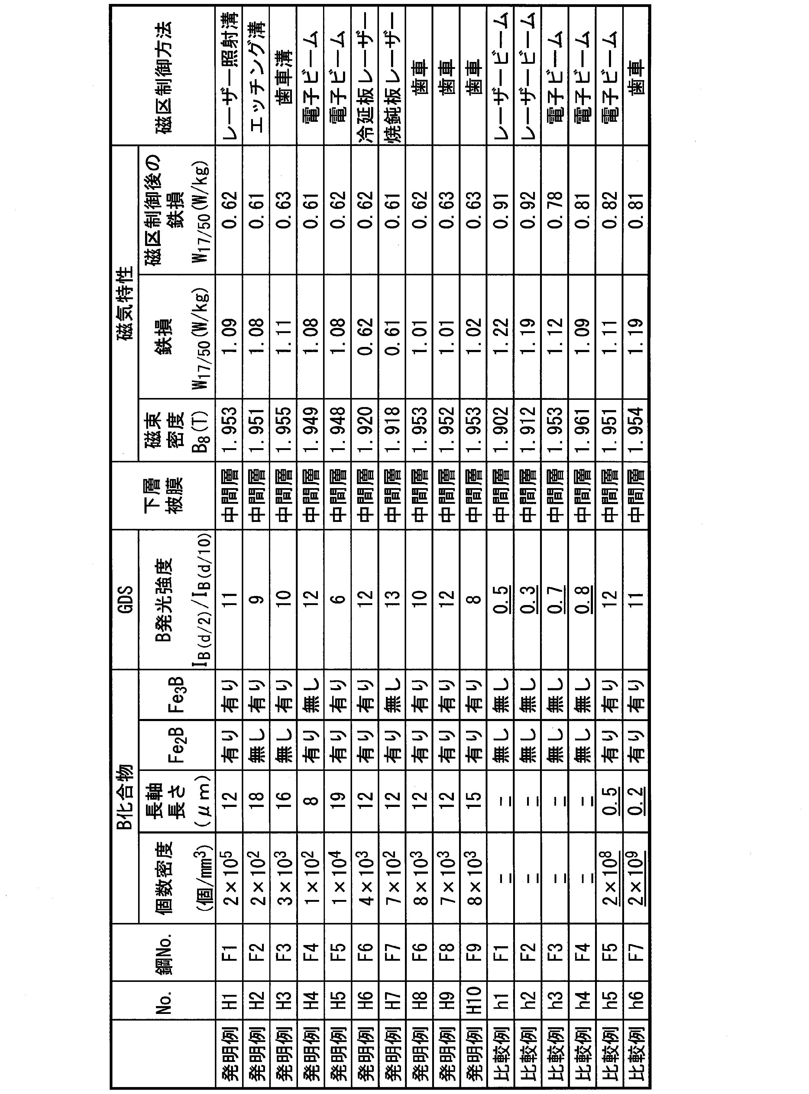
Claims (4)
- 母材鋼板と;
前記母材鋼板上に接して形成された下層被膜と;
前記下層被膜上に接して形成され、燐酸塩とコロイド状シリカとを主体とする絶縁被膜と;
を備え、
前記母材鋼板は、化学成分として、質量%で、
C:0.085%以下;
Si:0.80~7.00%;
Mn:0.05~1.00%;
Al:0.010~0.065%;
N:0.0040%以下;
Seq=S+0.406・Se:0.015%以下;
B:0.0005~0.0080%;
を含有し、
残部Fe及び不純物からなり、
前記母材鋼板は、長軸長さが1μm以上20μm以下のB化合物を1×10~1×10⁶個/mm3の個数密度で含有し、
前記下層被膜は、フォルステライトが主体であるグラス被膜、又は、酸化珪素が主体である中間層である
ことを特徴とする方向性電磁鋼板。 - 前記下層被膜が前記グラス被膜であって、
前記絶縁被膜及び前記グラス被膜を除去してグロー放電発光分析で測定し、前記母材鋼板の板厚中心よりも前記グラス被膜側を、前記グラス被膜側の表層領域と前記表層領域と前記板厚中心との間の中心領域との二つに分け、前記中心領域に到達するまでのスパッタ時間をt(center)とし、前記表層領域に到達するまでのスパッタ時間をt(surface)としたとき、前記t(center)におけるBの発光強度IB_t(center)と、前記t(surface)におけるBの発光強度IB_t(surface)とが、下記式(1)を満たす
ことを特徴とする請求項1に記載の方向性電磁鋼板。
IB_t(center)>IB_t(surface)・・・・・・・・・・・・・・・・(1) - 前記下層被膜が前記中間層であって、
前記母材鋼板と前記中間層との合計厚さをdとし、グロー放電発光分析で前記中間層の表面からBの発光強度を測定したときの前記中間層の前記表面からd/2の深さ位置におけるBの発光強度IB(d/2)と、前記中間層の前記表面からd/10の深さ位置におけるBの発光強度IB(d/10)とが、下記式(2)を満たす
ことを特徴とする請求項1に記載の方向性電磁鋼板。
IB(d/2)>IB(d/10) ・・・・・・・・・・・・・・(2) - 前記B化合物がFe2BとFe3Bとの少なくとも一方であることを特徴とする請求項1~3の何れか1項に記載の方向性電磁鋼板。
Priority Applications (8)
| Application Number | Priority Date | Filing Date | Title |
|---|---|---|---|
| US16/962,798 US11469017B2 (en) | 2018-01-25 | 2019-01-24 | Grain oriented electrical steel sheet |
| JP2019567147A JP7010305B2 (ja) | 2018-01-25 | 2019-01-24 | 方向性電磁鋼板 |
| PL19744050.6T PL3744870T3 (pl) | 2018-01-25 | 2019-01-24 | Blacha cienka ze stali elektrotechnicznej o ziarnach zorientowanych |
| KR1020207021397A KR102438155B1 (ko) | 2018-01-25 | 2019-01-24 | 방향성 전자 강판 |
| BR112020014283-2A BR112020014283B1 (pt) | 2018-01-25 | 2019-01-24 | Chapa de aço elétrico de grão orientado |
| EP19744050.6A EP3744870B1 (en) | 2018-01-25 | 2019-01-24 | Grain oriented electrical steel sheet |
| RU2020125130A RU2740749C1 (ru) | 2018-01-25 | 2019-01-24 | Лист из электротехнической стали с ориентированной зеренной структурой |
| CN201980009355.8A CN111655886B (zh) | 2018-01-25 | 2019-01-24 | 方向性电磁钢板 |
Applications Claiming Priority (2)
| Application Number | Priority Date | Filing Date | Title |
|---|---|---|---|
| JP2018-010203 | 2018-01-25 | ||
| JP2018010203 | 2018-01-25 |
Publications (1)
| Publication Number | Publication Date |
|---|---|
| WO2019146694A1 true WO2019146694A1 (ja) | 2019-08-01 |
Family
ID=67395410
Family Applications (1)
| Application Number | Title | Priority Date | Filing Date |
|---|---|---|---|
| PCT/JP2019/002258 WO2019146694A1 (ja) | 2018-01-25 | 2019-01-24 | 方向性電磁鋼板 |
Country Status (8)
| Country | Link |
|---|---|
| US (1) | US11469017B2 (ja) |
| EP (1) | EP3744870B1 (ja) |
| JP (1) | JP7010305B2 (ja) |
| KR (1) | KR102438155B1 (ja) |
| CN (1) | CN111655886B (ja) |
| PL (1) | PL3744870T3 (ja) |
| RU (1) | RU2740749C1 (ja) |
| WO (1) | WO2019146694A1 (ja) |
Cited By (4)
| Publication number | Priority date | Publication date | Assignee | Title |
|---|---|---|---|---|
| WO2020149344A1 (ja) * | 2019-01-16 | 2020-07-23 | 日本製鉄株式会社 | フォルステライト皮膜を有しない絶縁皮膜密着性に優れる方向性電磁鋼板 |
| CN114630918A (zh) * | 2019-12-09 | 2022-06-14 | 杰富意钢铁株式会社 | 无方向性电磁钢板和马达铁芯及其制造方法 |
| EP4032995A4 (en) * | 2019-09-19 | 2022-10-19 | Nippon Steel Corporation | ORIENTED ELECTROMAGNETIC STEEL SHEET |
| WO2022250162A1 (ja) * | 2021-05-28 | 2022-12-01 | Jfeスチール株式会社 | 方向性電磁鋼板の製造方法 |
Families Citing this family (1)
| Publication number | Priority date | Publication date | Assignee | Title |
|---|---|---|---|---|
| CN112646966B (zh) * | 2020-12-17 | 2023-01-10 | 首钢智新迁安电磁材料有限公司 | 一种无底层取向硅钢的制备方法及其产品 |
Citations (14)
| Publication number | Priority date | Publication date | Assignee | Title |
|---|---|---|---|---|
| US3905843A (en) | 1974-01-02 | 1975-09-16 | Gen Electric | Method of producing silicon-iron sheet material with boron addition and product |
| US3905842A (en) | 1974-01-07 | 1975-09-16 | Gen Electric | Method of producing silicon-iron sheet material with boron addition and product |
| JPH01230721A (ja) | 1987-11-20 | 1989-09-14 | Nippon Steel Corp | 磁束密度の高い一方向性珪素鋼板の製造方法 |
| JPH01283324A (ja) | 1988-05-11 | 1989-11-14 | Nippon Steel Corp | 磁束密度の高い一方向性電磁鋼板の製造方法 |
| JPH10140243A (ja) | 1996-11-13 | 1998-05-26 | Kawasaki Steel Corp | 極めて鉄損の低い高磁束密度方向性電磁鋼板の製造方法 |
| JPH11269544A (ja) * | 1998-03-20 | 1999-10-05 | Kawasaki Steel Corp | 高磁束密度低鉄損方向性電磁鋼板の製造方法 |
| JP2000129352A (ja) * | 1998-10-22 | 2000-05-09 | Nippon Steel Corp | 磁束密度の高い一方向性電磁鋼板の製造方法 |
| JP2004332071A (ja) * | 2003-05-09 | 2004-11-25 | Jfe Steel Kk | 高磁束密度方向性電磁鋼板の製造方法 |
| WO2011007771A1 (ja) | 2009-07-13 | 2011-01-20 | 新日本製鐵株式会社 | 方向性電磁鋼板の製造方法 |
| WO2011007817A1 (ja) | 2009-07-17 | 2011-01-20 | 新日本製鐵株式会社 | 方向性電磁鋼板の製造方法 |
| KR20120071825A (ko) * | 2010-12-23 | 2012-07-03 | 주식회사 포스코 | 자성이 우수한 방향성 전기강판 및 이의 제조방법 |
| WO2012096350A1 (ja) * | 2011-01-12 | 2012-07-19 | 新日本製鐵株式会社 | 方向性電磁鋼板及びその製造方法 |
| JP2012144777A (ja) * | 2011-01-12 | 2012-08-02 | Nippon Steel Corp | 電磁鋼板素材及び方向性電磁鋼板の製造方法 |
| JP2018010203A (ja) | 2016-07-14 | 2018-01-18 | 株式会社半導体エネルギー研究所 | 表示装置およびその駆動方法、表示モジュールならびに電子機器 |
Family Cites Families (10)
| Publication number | Priority date | Publication date | Assignee | Title |
|---|---|---|---|---|
| DE3882502T2 (de) | 1987-11-20 | 1993-11-11 | Nippon Steel Corp | Verfahren zur Herstellung von kornorientierten Elektrostahlblechen mit hoher Flussdichte. |
| US5643370A (en) | 1995-05-16 | 1997-07-01 | Armco Inc. | Grain oriented electrical steel having high volume resistivity and method for producing same |
| US5885371A (en) | 1996-10-11 | 1999-03-23 | Kawasaki Steel Corporation | Method of producing grain-oriented magnetic steel sheet |
| JP2002220642A (ja) * | 2001-01-29 | 2002-08-09 | Kawasaki Steel Corp | 鉄損の低い方向性電磁鋼板およびその製造方法 |
| PL2022874T3 (pl) * | 2006-05-19 | 2012-12-31 | Nippon Steel Corp | Teksturowana elektrotechniczna blacha stalowa mająca film izolacyjny o wysokiej wytrzymałości na rozciąganie i sposób obróbki filmu izolacyjnego |
| JP5332707B2 (ja) * | 2009-02-20 | 2013-11-06 | 新日鐵住金株式会社 | 磁気特性が極めて優れた方向性電磁鋼板の製造方法 |
| RU2503728C1 (ru) * | 2010-05-25 | 2014-01-10 | Ниппон Стил Энд Сумитомо Метал Корпорейшн | Способ изготовления листа электротехнической стали с ориентированной зеренной структурой |
| US20160108488A1 (en) * | 2014-10-15 | 2016-04-21 | Sms Siemag Ag | Process for producing grain-oriented electrical steel strip and grain-oriented electrical steel strip obtained according to said process |
| KR101633255B1 (ko) | 2014-12-18 | 2016-07-08 | 주식회사 포스코 | 방향성 전기강판 및 그 제조방법 |
| KR101693516B1 (ko) * | 2014-12-24 | 2017-01-06 | 주식회사 포스코 | 방향성 전기강판 및 그 제조방법 |
-
2019
- 2019-01-24 EP EP19744050.6A patent/EP3744870B1/en active Active
- 2019-01-24 JP JP2019567147A patent/JP7010305B2/ja active Active
- 2019-01-24 WO PCT/JP2019/002258 patent/WO2019146694A1/ja unknown
- 2019-01-24 US US16/962,798 patent/US11469017B2/en active Active
- 2019-01-24 KR KR1020207021397A patent/KR102438155B1/ko active IP Right Grant
- 2019-01-24 RU RU2020125130A patent/RU2740749C1/ru active
- 2019-01-24 PL PL19744050.6T patent/PL3744870T3/pl unknown
- 2019-01-24 CN CN201980009355.8A patent/CN111655886B/zh active Active
Patent Citations (14)
| Publication number | Priority date | Publication date | Assignee | Title |
|---|---|---|---|---|
| US3905843A (en) | 1974-01-02 | 1975-09-16 | Gen Electric | Method of producing silicon-iron sheet material with boron addition and product |
| US3905842A (en) | 1974-01-07 | 1975-09-16 | Gen Electric | Method of producing silicon-iron sheet material with boron addition and product |
| JPH01230721A (ja) | 1987-11-20 | 1989-09-14 | Nippon Steel Corp | 磁束密度の高い一方向性珪素鋼板の製造方法 |
| JPH01283324A (ja) | 1988-05-11 | 1989-11-14 | Nippon Steel Corp | 磁束密度の高い一方向性電磁鋼板の製造方法 |
| JPH10140243A (ja) | 1996-11-13 | 1998-05-26 | Kawasaki Steel Corp | 極めて鉄損の低い高磁束密度方向性電磁鋼板の製造方法 |
| JPH11269544A (ja) * | 1998-03-20 | 1999-10-05 | Kawasaki Steel Corp | 高磁束密度低鉄損方向性電磁鋼板の製造方法 |
| JP2000129352A (ja) * | 1998-10-22 | 2000-05-09 | Nippon Steel Corp | 磁束密度の高い一方向性電磁鋼板の製造方法 |
| JP2004332071A (ja) * | 2003-05-09 | 2004-11-25 | Jfe Steel Kk | 高磁束密度方向性電磁鋼板の製造方法 |
| WO2011007771A1 (ja) | 2009-07-13 | 2011-01-20 | 新日本製鐵株式会社 | 方向性電磁鋼板の製造方法 |
| WO2011007817A1 (ja) | 2009-07-17 | 2011-01-20 | 新日本製鐵株式会社 | 方向性電磁鋼板の製造方法 |
| KR20120071825A (ko) * | 2010-12-23 | 2012-07-03 | 주식회사 포스코 | 자성이 우수한 방향성 전기강판 및 이의 제조방법 |
| WO2012096350A1 (ja) * | 2011-01-12 | 2012-07-19 | 新日本製鐵株式会社 | 方向性電磁鋼板及びその製造方法 |
| JP2012144777A (ja) * | 2011-01-12 | 2012-08-02 | Nippon Steel Corp | 電磁鋼板素材及び方向性電磁鋼板の製造方法 |
| JP2018010203A (ja) | 2016-07-14 | 2018-01-18 | 株式会社半導体エネルギー研究所 | 表示装置およびその駆動方法、表示モジュールならびに電子機器 |
Non-Patent Citations (1)
| Title |
|---|
| See also references of EP3744870A4 |
Cited By (4)
| Publication number | Priority date | Publication date | Assignee | Title |
|---|---|---|---|---|
| WO2020149344A1 (ja) * | 2019-01-16 | 2020-07-23 | 日本製鉄株式会社 | フォルステライト皮膜を有しない絶縁皮膜密着性に優れる方向性電磁鋼板 |
| EP4032995A4 (en) * | 2019-09-19 | 2022-10-19 | Nippon Steel Corporation | ORIENTED ELECTROMAGNETIC STEEL SHEET |
| CN114630918A (zh) * | 2019-12-09 | 2022-06-14 | 杰富意钢铁株式会社 | 无方向性电磁钢板和马达铁芯及其制造方法 |
| WO2022250162A1 (ja) * | 2021-05-28 | 2022-12-01 | Jfeスチール株式会社 | 方向性電磁鋼板の製造方法 |
Also Published As
| Publication number | Publication date |
|---|---|
| US20210027922A1 (en) | 2021-01-28 |
| JPWO2019146694A1 (ja) | 2021-01-28 |
| EP3744870B1 (en) | 2023-05-10 |
| CN111655886A (zh) | 2020-09-11 |
| BR112020014283A2 (pt) | 2020-12-08 |
| PL3744870T3 (pl) | 2023-07-31 |
| EP3744870A1 (en) | 2020-12-02 |
| KR20200097346A (ko) | 2020-08-18 |
| EP3744870A4 (en) | 2021-06-02 |
| CN111655886B (zh) | 2022-08-30 |
| KR102438155B1 (ko) | 2022-08-31 |
| JP7010305B2 (ja) | 2022-02-10 |
| US11469017B2 (en) | 2022-10-11 |
| RU2740749C1 (ru) | 2021-01-20 |
Similar Documents
| Publication | Publication Date | Title |
|---|---|---|
| WO2019146694A1 (ja) | 方向性電磁鋼板 | |
| US20220112573A1 (en) | Method for producing grain oriented electrical steel sheet | |
| CN115485414B (zh) | 方向性电磁钢板及方向性电磁钢板的制造方法 | |
| US20220081747A1 (en) | Method for producing grain oriented electrical steel sheet | |
| WO2020149347A1 (ja) | 方向性電磁鋼板の製造方法 | |
| US20220081746A1 (en) | Method for producing grain oriented electrical steel sheet | |
| WO2019146697A1 (ja) | 方向性電磁鋼板 | |
| US20220119905A1 (en) | Method for producing grain oriented electrical steel sheet | |
| JP7339549B2 (ja) | フォルステライト皮膜を有しない絶縁皮膜密着性に優れる方向性電磁鋼板 | |
| RU2771130C1 (ru) | Способ производства листа электротехнической стали с ориентированной зеренной структурой | |
| US11946113B2 (en) | Method for producing grain oriented electrical steel sheet | |
| US20220098693A1 (en) | Method for producing grain oriented electrical steel sheet | |
| US20220106661A1 (en) | Method for producing grain oriented electrical steel sheet | |
| KR20220044836A (ko) | 방향성 전자 강판의 제조 방법 | |
| JP2005120452A (ja) | 磁気特性および被膜特性に優れた方向性電磁鋼板の製造方法 |
Legal Events
| Date | Code | Title | Description |
|---|---|---|---|
| 121 | Ep: the epo has been informed by wipo that ep was designated in this application |
Ref document number: 19744050 Country of ref document: EP Kind code of ref document: A1 |
|
| ENP | Entry into the national phase |
Ref document number: 2019567147 Country of ref document: JP Kind code of ref document: A |
|
| ENP | Entry into the national phase |
Ref document number: 20207021397 Country of ref document: KR Kind code of ref document: A |
|
| NENP | Non-entry into the national phase |
Ref country code: DE |
|
| ENP | Entry into the national phase |
Ref document number: 2019744050 Country of ref document: EP Effective date: 20200825 |
|
| REG | Reference to national code |
Ref country code: BR Ref legal event code: B01A Ref document number: 112020014283 Country of ref document: BR |
|
| ENP | Entry into the national phase |
Ref document number: 112020014283 Country of ref document: BR Kind code of ref document: A2 Effective date: 20200713 |