WO2022244613A1 - 超音波シール用多層フィルム、及び積層体 - Google Patents
超音波シール用多層フィルム、及び積層体 Download PDFInfo
- Publication number
- WO2022244613A1 WO2022244613A1 PCT/JP2022/019236 JP2022019236W WO2022244613A1 WO 2022244613 A1 WO2022244613 A1 WO 2022244613A1 JP 2022019236 W JP2022019236 W JP 2022019236W WO 2022244613 A1 WO2022244613 A1 WO 2022244613A1
- Authority
- WO
- WIPO (PCT)
- Prior art keywords
- ultrasonic
- multilayer film
- sealing
- ultrasonic sealing
- layer
- Prior art date
- Legal status (The legal status is an assumption and is not a legal conclusion. Google has not performed a legal analysis and makes no representation as to the accuracy of the status listed.)
- Ceased
Links
Images




Classifications
-
- B—PERFORMING OPERATIONS; TRANSPORTING
- B32—LAYERED PRODUCTS
- B32B—LAYERED PRODUCTS, i.e. PRODUCTS BUILT-UP OF STRATA OF FLAT OR NON-FLAT, e.g. CELLULAR OR HONEYCOMB, FORM
- B32B27/00—Layered products comprising a layer of synthetic resin
- B32B27/32—Layered products comprising a layer of synthetic resin comprising polyolefins
-
- Y—GENERAL TAGGING OF NEW TECHNOLOGICAL DEVELOPMENTS; GENERAL TAGGING OF CROSS-SECTIONAL TECHNOLOGIES SPANNING OVER SEVERAL SECTIONS OF THE IPC; TECHNICAL SUBJECTS COVERED BY FORMER USPC CROSS-REFERENCE ART COLLECTIONS [XRACs] AND DIGESTS
- Y02—TECHNOLOGIES OR APPLICATIONS FOR MITIGATION OR ADAPTATION AGAINST CLIMATE CHANGE
- Y02W—CLIMATE CHANGE MITIGATION TECHNOLOGIES RELATED TO WASTEWATER TREATMENT OR WASTE MANAGEMENT
- Y02W30/00—Technologies for solid waste management
- Y02W30/50—Reuse, recycling or recovery technologies
- Y02W30/80—Packaging reuse or recycling, e.g. of multilayer packaging
Definitions
- the present invention relates to a multilayer film for ultrasonic sealing and a laminate.
- Multilayer films such as oriented polypropylene OPP / non-oriented polypropylene CPP have been developed in order to respond to monomaterialization, as opposed to the conventional multi-layer laminate structure of different materials (e.g., oriented polyethylene terephthalate OPET / non-oriented polypropylene CPP multi-layer film). is required.
- the multilayer film made of OPP/CPP which is compatible with conventional mono-materialization, has a problem that heat resistance of the surface of the multilayer film decreases due to the difference in heat resistance between the materials, and there is concern that the packaging suitability may decrease. .
- a multilayer film that can be ultrasonically sealed using ultrasonic waves that can heat only the sealing surface is being studied.
- a central layer is an ethylene-polar monomer copolymer such as an ethylene-alkyl (meth)acrylate copolymer, and random
- a laminated film has been proposed in which a surface layer made of a mixed resin of polypropylene and an ⁇ -olefin elastomer is formed, and an amorphous polyolefin layer is interposed between the central layer and the surface layer (see, for example, Patent Document 1).
- the laminated film proposed above which is suitable for ultrasonic sealing, contains an ethylene-polar monomer copolymer and cannot be made into a monomaterial. Therefore, there is a demand for a multilayer film resin structure that can be used as a monomaterial and is suitable for ultrasonic sealing.
- the object of the present invention is to solve the above-mentioned conventional problems and to achieve the following objectives. That is, it is an object of the present invention to provide a multilayer film for ultrasonic sealing that can be applied to a monomaterial, can be ultrasonically welded, and has a narrow sealing width and uniform and stable ultrasonic sealing strength.
- the present invention is based on the above findings by the present inventors, and means for solving the above problems are as follows. Namely ⁇ 1> a thermoplastic resin layer containing a thermoplastic resin; At least a seal layer containing random polypropylene and an ⁇ -olefin resin, The ⁇ -olefin resin contains a butene-based ⁇ -olefin resin,
- the multilayer film for ultrasonic sealing is characterized in that it can be sealed by ultrasonic waves.
- ⁇ 3> The multilayer film for ultrasonic sealing according to any one of ⁇ 1> and ⁇ 2>, wherein the seal layer contains the butene-based ⁇ -olefin resin in an amount of 20% by mass or more and 50% by mass or less.
- ⁇ 4> The multilayer film for ultrasonic sealing according to any one of ⁇ 1> to ⁇ 3>, wherein the sealing layer has a thickness of 20% or more.
- ⁇ 5> The multilayer film for ultrasonic sealing according to any one of ⁇ 1> to ⁇ 4>, having a total thickness of 40 ⁇ m or more.
- ⁇ 6> The multilayer film for ultrasonic sealing according to any one of ⁇ 1> to ⁇ 5>, wherein the heat of fusion measured by differential scanning calorimetry is 65 mJ/mg or less.
- ⁇ 7> The multilayer film for ultrasonic sealing according to any one of ⁇ 1> to ⁇ 6>, wherein the thermoplastic resin contains at least one of polyethylene and polypropylene.
- ⁇ 8> A laminate obtained by ultrasonically sealing the multilayer film for ultrasonic sealing according to any one of ⁇ 1> to ⁇ 7> and a thermoplastic resin film.
- the above-mentioned problems in the conventional art can be solved, the above-mentioned objects can be achieved, it is possible to deal with monomaterialization, ultrasonic welding is possible, and a uniform and stable ultrasonic seal with a narrow seal width
- a multilayer film for ultrasonic sealing can be provided that can have strength.
- FIG. 1 is a schematic cross-sectional view showing an example of the multilayer film for ultrasonic sealing of the present invention.
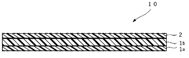
- FIG. 2 is a schematic cross-sectional view showing another example of the multilayer film for ultrasonic sealing of the present invention.
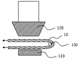
- FIG. 3A is a schematic cross-sectional view (No. 1) showing an example of an ultrasonic sealing device used for ultrasonic welding of the multilayer film for ultrasonic sealing of the present invention.
- FIG. 3B is a schematic cross-sectional view (No. 2) showing an example of an ultrasonic sealing device used for ultrasonic welding of the multilayer film for ultrasonic sealing of the present invention.
- FIG. 3C is a schematic cross-sectional view (No. 3) showing an example of an ultrasonic sealing device used for ultrasonic welding of the multilayer film for ultrasonic sealing of the present invention.
- FIG. 4 is a graph showing the results of measuring the sealing strength of the multilayer film for ultrasonic sealing in Examples.
- the ultrasonic sealing multilayer film of the present invention has at least a thermoplastic resin layer and a sealing layer, and is ultrasonically sealable.
- the thermoplastic resin layer contains a thermoplastic resin as a main resin component.
- the thermoplastic resin layer may be a single layer or multiple layers.
- Said thermoplastic layer may be a surface layer on which printing of the packaging film can be provided.
- thermoplastic resin is not particularly limited and can be appropriately selected from known thermoplastic resins depending on the intended purpose. Examples thereof include ⁇ -olefin resins, styrene resins, ester resins, and acrylic resins. Among these, the ⁇ -olefin resin is preferable because it can be made into a monomaterial.
- ⁇ -olefin resin examples include homopolymers of ⁇ -olefin monomers (polyethylene homopolymer, polypropylene homopolymer, etc.); copolymers mainly composed of ⁇ -olefin monomers (propylene-ethylene block copolymer polymer, propylene-ethylene random copolymer, ethylene-butene-1 copolymer, propylene-butene-1 copolymer, etc.). These may be used individually by 1 type, and may use 2 or more types together. Among these, ethylene homopolymers, propylene homopolymers, propylene-ethylene block copolymers, and propylene-ethylene random copolymers containing at least one of polyethylene and polypropylene are preferred.
- the content of the ⁇ -olefin monomer in the ⁇ -olefin resin is preferably 50 mol % to 100 mol %, more preferably 70 mol % to 100 mol %.
- the melt flow rate (MFR) of the thermoplastic resin is not particularly limited and can be appropriately selected according to the purpose. 50.0 g/10 minutes is preferred, 3.0 g/10 minutes to 45.0 g/10 minutes is more preferred, and 3.0 g/10 minutes to 12.0 g/10 minutes is even more preferred.
- the melt flow rate (MFR) is a value measured at 190° C. under a load of 2.16 kg (21.18 N) according to JISK7210.
- the density of the thermoplastic resin is not particularly limited and can be appropriately selected according to the purpose. 93 g/cm 3 is more preferred.
- the melting point of the thermoplastic resin is not particularly limited and can be appropriately selected according to the purpose.
- the melting point can be measured using a differential scanning calorimeter (DSC) (for example, DSC7020 manufactured by Hitachi High-Tech Science Co., Ltd.).
- DSC differential scanning calorimeter
- the sealing layer contains random polypropylene and ⁇ -olefin resin as main resin components.
- the random polypropylene is a random copolymer of 90% to 98% by mass of propylene and 10% to 2% by mass of ethylene and/or an ⁇ -olefin having 4 or more carbon atoms. Examples of the ⁇ -olefin having 4 or more carbon atoms include 1-butene.
- the random polypropylene may be used singly or in combination of two or more.
- the content of the random polypropylene is preferably 50% by mass or more and 95% by mass or less, more preferably 50% by mass or more and 70% by mass or less, relative to the total amount of the resin components contained in the seal layer.
- the melt flow rate (MFR) of the random polypropylene is not particularly limited and can be appropriately selected according to the purpose. 50.0 g/10 minutes is preferred, 3.0 g/10 minutes to 45.0 g/10 minutes is more preferred, and 3.0 g/10 minutes to 12.0 g/10 minutes is even more preferred.
- the density of the random polypropylene is not particularly limited and can be appropriately selected according to the purpose. /cm 3 is more preferred.
- the melting point of the random polypropylene is not particularly limited and can be appropriately selected according to the purpose, but is preferably 110°C to 160°C, more preferably 120°C to 140°C.
- the ⁇ -olefin resin contains at least a butene-based ⁇ -olefin resin and, if necessary, an ⁇ -olefin resin other than the butene-based ⁇ -olefin resin.
- the ⁇ -olefin resin is not particularly limited and can be appropriately selected depending on the intended purpose. -propylene copolymer, ethylene-butene-1 copolymer, propylene-butene-1 copolymer and the like. These may be used individually by 1 type, and may use 2 or more types together.
- the content of the ⁇ -olefin monomer in the ⁇ -olefin resin is preferably 50 mol % to 100 mol %, more preferably 70 mol % to 100 mol %.
- the melt flow rate (MFR) of the ⁇ -olefin resin other than the butene-based ⁇ -olefin resin is not particularly limited and can be appropriately selected according to the purpose. , preferably 1.0 g / 10 minutes to 50.0 g / 10 minutes, more preferably 2.0 g / 10 minutes to 45.0 g / 10 minutes, even more preferably 2.0 g / 10 minutes to 10.0 g / 10 minutes .
- the density of the ⁇ - olefin resin other than the butene - based ⁇ -olefin resin is not particularly limited and can be appropriately selected according to the purpose. 87 g/cm 3 to 0.90 g/cm 3 is more preferable.
- the melting point of the ⁇ -olefin resin other than the butene-based ⁇ -olefin resin is not particularly limited and can be appropriately selected according to the purpose.
- butene-based ⁇ -olefin resin-- The butene-based ⁇ -olefin resin is not particularly limited and can be appropriately selected according to the purpose. Examples include 1-butene copolymers and propylene-1-butene copolymers. Among these, a propylene-1-butene copolymer is preferred. These may be used individually by 1 type, and may use 2 or more types together.
- the content of the butene-1 monomer in the butene-based ⁇ -olefin resin is preferably 50 mol % to 100 mol %, more preferably 70 mol % to 100 mol %.
- the melt flow rate (MFR) of the butene-based ⁇ -olefin resin is not particularly limited and can be appropriately selected according to the purpose. 10 minutes to 50.0 g/10 minutes is preferred, 3.0 g/10 minutes to 45.0 g/10 minutes is more preferred, and 3.0 g/10 minutes to 12.0 g/10 minutes is even more preferred.
- the density of the butene - based ⁇ - olefin resin is not particularly limited and can be appropriately selected according to the purpose. 0.92 g/cm 3 is more preferred.
- the melting point of the butene-based ⁇ -olefin resin is not particularly limited and can be appropriately selected according to the purpose. More preferred.
- the content of the butene-based ⁇ -olefin resin is preferably 5% by mass or more and 50% by mass or less, more preferably 10% by mass or more and 50% by mass or less, based on the total amount of the resin components contained in the seal layer. It is more preferably 50% by mass or less, and particularly preferably 20% by mass or more and 50% by mass or less.
- the content is 5% by mass or more and 50% by mass or less, it is advantageous in terms of exhibiting ultrasonic sealing properties. Further, when the content is 20% by mass or more and 50% by mass or less, it is particularly advantageous in terms of ensuring uniform and stable ultrasonic sealing performance over the entire sealing length.
- the mass ratio (b2/b1) of the butene-based ⁇ -olefin resin (b2) to the random polypropylene (b1) in the seal layer is not particularly limited and can be appropriately selected depending on the purpose, but is 5/95. 50/50 is preferred, 10/90 to 50/50 is more preferred, 20/80 to 50/50 is even more preferred, and 30/70 to 50/50 is particularly preferred.
- the resin of the thermoplastic resin layer and the seal layer contains other components such as antioxidants, ultraviolet absorbers, antistatic agents, and lubricants (antiblocking agents, slip agents) commonly used in polyolefins. may be blended as appropriate.
- the thermoplastic resin layer in the multilayer film for ultrasonic sealing may be a single layer or a plurality of layers.
- the plurality of thermoplastic resin layers may have the same composition or different compositions.
- the thermoplastic resin layer is a single layer
- the multilayer film for ultrasonic sealing is a multilayer film laminated in the order of thermoplastic resin layer/seal layer.
- the thermoplastic resin layer is a plurality of layers
- the thermoplastic resin layer has a base layer that serves as a surface layer of the multilayer film for ultrasonic sealing and an intermediate layer (one to multiple layers).
- the multilayer film for ultrasonic sealing is a multilayer film laminated in the order of base layer (thermoplastic resin layer)/intermediate layer (thermoplastic resin layer)/seal layer.
- the multilayer film for ultrasonic sealing may be a coextrusion multilayer film in which each layer is extruded and laminated together, or may be a laminate film in which some layers are adhered and laminated.
- the adhesion method for laminating the additional base material layer is not particularly limited and can be appropriately selected according to the purpose. Examples thereof include dry lamination, wet lamination, non-solvent lamination and extrusion lamination.
- the multilayer film for ultrasonic sealing is basically transparent and has a smooth surface.
- the mixed resin layer on both sides or one side of the multilayer film for ultrasonic sealing may be subjected to a corona discharge treatment to impart printability.
- both sides or one side of the multilayer film for ultrasonic sealing may be embossed to give an aperture pattern such as a satin finish.
- the total thickness of the multilayer film for ultrasonic sealing is not particularly limited and can be appropriately selected according to the purpose. More preferably, the thickness is 90 ⁇ m or more.
- the average thickness of a single layer or each layer of the thermoplastic resin layer is not particularly limited and can be appropriately selected according to the purpose.
- the total average thickness of each layer is not particularly limited and can be appropriately selected according to the purpose.
- the thickness of the thermoplastic resin layer is not particularly limited and can be appropriately selected according to the purpose. (%) is preferably 90% or less, more preferably 20% to 90%, even more preferably 50% to 80%.
- the average thickness of the sealing layer is not particularly limited and can be appropriately selected according to the purpose, but is preferably 3 ⁇ m to 30 ⁇ m, more preferably 5 ⁇ m to 25 ⁇ m, and even more preferably 10 ⁇ m to 20 ⁇ m.
- the thickness of the seal layer is not particularly limited and can be appropriately selected according to the purpose. 10% or more is preferable, 20% or more is more preferable, and 30% or more is still more preferable. Also, it is preferably 10% or more and 50% or less, more preferably 20% or more and 50% or less, and even more preferably 30% or more and 50% or less. When the thickness is 10% or more, it is advantageous in terms of exhibiting ultrasonic sealability. Further, when the thickness is 20% or more, it is particularly advantageous in that uniform and stable ultrasonic sealing properties are ensured from 50% of the sealing length to the entire length.
- the heat of fusion measured by differential scanning calorimetry (DSC) in the multilayer film for ultrasonic sealing is preferably 65 mJ/mg or less from the viewpoint of uniform weldability by ultrasonic sealing.
- the amount of heat of fusion measured by differential scanning calorimetry (DSC) is the amount of heat of fusion in the first temperature rise, and is measured in the following procedure using, for example, a differential scanning calorimeter (manufactured by Hitachi High-Tech Science Co., Ltd., DSC7020). be able to.
- a multilayer film for ultrasonic sealing which is a target sample
- the sample container is placed on a holder unit, and set in an electric furnace.
- the sample is heated from 30° C. to 200° C. at a temperature increase rate of 10° C./min (first temperature increase), and the DSC curve is measured using a differential scanning calorimeter. From the obtained DSC curve, an analysis program for a differential scanning calorimeter is used to select the DSC curve at the time of the first temperature increase, and the heat of fusion [mJ/mg] of the target sample at the first temperature increase can be obtained. can.
- the method of sealing by ultrasonic waves is not particularly limited, and a known ultrasonic sealing method, a method using a known ultrasonic sealing device, or the like can be appropriately selected according to the purpose.
- the “ultrasonic seal” is a combination of an “ultrasonic horn” that transmits vibration energy by ultrasonic waves and a fixing jig “anvil” using ultrasonic vibration amplitude that converts electrical energy into mechanical energy. It is a technology in which a film to be joined is sandwiched in between, and frictional energy is generated uniformly at the interfaces of the film materials, resulting in instantaneous fusion and welding.
- the terms “ultrasonic sealing”, “ultrasonic welding”, “ultrasonic fusion welding”, and “ultrasonic fusion bonding” can be synonymous with each other.
- the ultrasonic horn may be arranged vertically above the object to be welded and the anvil, or horizontally with respect to the object to be welded and the anvil.
- Ultrasonic horns vibrate with ultrasonic waves, typically between 20 kHz and 40 kHz, to transfer energy under pressure, typically in the form of frictional heat, to the joints to be joined. Due to the frictional heat and pressure, a portion of at least one of the objects to be joined softens or melts, thereby joining the objects to be joined together.
- the "bonding object” is not particularly limited as long as it contains at least the multilayer film for ultrasonic sealing of the present invention, and can be appropriately selected according to the purpose.
- Two multilayer films may be arranged so that the seal layers are in contact with each other, and a series (one sheet) of the multilayer film for ultrasonic sealing may be folded so that the seal layers are in contact with each other.
- the ultrasonic sealing multilayer film and the thermoplastic resin film are arranged such that the sealing layer of the ultrasonic sealing multilayer film is in contact with the thermoplastic resin film.
- a laminate to be described later can be obtained by ultrasonically sealing the portions where the seal layers are in contact with each other and the portions where the seal layers are in contact with the thermoplastic resin film to form joints.
- the ultrasonic waves in the ultrasonic seal are not particularly limited, and elastic vibration waves (sound waves) having a high frequency that cannot be heard by human ears can be appropriately selected according to the purpose.
- the frequency of the ultrasonic waves is preferably 16 kHz or higher, more preferably 20 kHz or higher, and particularly preferably 20 kHz or higher and 40 kHz or lower.
- the conditions such as pressure, amplitude, welding time, and hold time in the ultrasonic sealing change according to the type of object to be joined, frequency, and combination of conditions, and cannot be univocally defined, but there are no particular restrictions. can be selected as appropriate depending on the purpose.
- the pressure means the pressing pressure of the ultrasonic horn against the object to be welded in the ultrasonic sealing device, and is expressed in units such as [Pa] (pascal), [MPa] (megapascal), and the like.
- the pressure is preferably 0.15 [MPa] to 0.3 [MPa], more preferably 0.25 [MPa] to 0.3 [MPa].
- the amplitude means the magnitude of ultrasonic vibration.
- the amplitude is preferably 20 ⁇ m or more and 50 ⁇ m or less, and more preferably 35 ⁇ m or more and 50 ⁇ m or less in order to have a uniform and stable seal strength.
- the welding time indicates the oscillation time of ultrasonic waves, and means the time during which the ultrasonic horn contacts and welds the object to be welded.
- the welding time is preferably 0.2 seconds or more and 1 second or less, more preferably 0.5 seconds or more and 1 second or less.
- the hold time means the holding time of the ultrasonic oscillator and the hardening time of the welded portion.
- the hold time is preferably 0.2 seconds or more and 1.0 seconds or less, more preferably 0.5 seconds or more and 1.0 seconds or less.
- Suitable examples of the ultrasonic sealing device include a continuous ultrasonic sealing type device, a device having a rotary ultrasonic horn, and the like.
- Such continuous ultrasonic sealing type devices are commonly known as "continuous ultrasonic fusion bonds".
- Continuous ultrasonic fusion bonding can generally be fed substantially continuously into an ultrasonic sealing device, and is used to substantially continuously seal objects to be bonded.
- the ultrasonic horn is usually fixed and the object to be welded moves underneath it.
- One type of continuous ultrasonic fusion bond uses a stationary horn and a rotating anvil face. During continuous ultrasonic fusion bonding, the object to be welded is pulled between the ultrasonic horn and the rotating anvil.
- the ultrasonic horn typically extends longitudinally toward the object to be joined, and vibrations are transmitted axially along the ultrasonic horn to the material.
- the ultrasonic horn In the device with a rotating ultrasonic horn, the ultrasonic horn is of rotary type, cylindrical and rotates about its longitudinal axis.
- the input vibration is in the axial direction of the ultrasonic horn and the output vibration is in the radial direction of the ultrasonic horn.
- the ultrasonic horn is placed in close proximity to the anvil, and the anvil is typically also rotatable such that the object to be welded passes between the cylindrical surfaces at a linear velocity substantially equal to the tangential velocity of the cylindrical surfaces. .
- ultrasonic seals examples include JP-A-2008-526552, JP-A-2010-195044, JP-A-2013-231249, JP-A-2015-16294, and US Pat. No. 5,976,316. and the disclosure of which is incorporated herein by reference.
- the laminate of the present invention includes at least the multilayer film for ultrasonic sealing of the present invention, and is a laminate obtained by arranging two sheets of the multilayer film for ultrasonic sealing so that the respective sealing layers are in contact with each other and sealing them by ultrasonic waves. It may be a laminate obtained by folding and arranging a series (one sheet) of the multilayer film for ultrasonic sealing so that the sealing layers are in contact with each other, and then sealing by ultrasonic waves, or A laminate obtained by arranging the multilayer film for ultrasonic sealing and a thermoplastic resin film so that the seal layer of the multilayer film for ultrasonic sealing is in contact with the thermoplastic resin film and sealing them by ultrasonic waves, good too.
- the laminate can be suitably used as a package.
- the package examples include packages for food such as western confectionery, snacks, bread, Japanese confectionery, and seasonings.
- the laminate can be made of a monomaterial and can be sealed by an ultrasonic seal capable of heating only the sealing surface, so that the width of the seal can be narrowed and the amount of material can be reduced.
- thermoplastic resin film The material of the thermoplastic resin film is not particularly limited and can be appropriately selected from known thermoplastic resins according to the purpose.
- ⁇ -olefin resin any of the ⁇ -olefin resins described for the thermoplastic resin layer can be appropriately employed.
- the ultrasonic sealing multilayer film 10 of the present invention is, for example, a multilayer film composed of a thermoplastic resin layer 1 and a sealing layer 2 and having two layers laminated, as shown in FIG. Further, as shown in FIG. 2, the multilayer film 10 for ultrasonic sealing of the present invention may have a plurality of thermoplastic resin layers, a thermoplastic resin layer (base layer) 1a, a thermoplastic resin layer ( It may be a multi-layer film consisting of an intermediate layer) 1b and a seal layer 2, which is laminated in the order of substrate layer/intermediate layer/seal layer.
- FIG. 3A to 3C are schematic cross-sectional views showing an example of an ultrasonic sealing device used for ultrasonic welding of the multilayer film for ultrasonic sealing of the present invention.
- the ultrasonic sealing device 100 has an anvil 110 and an ultrasonic horn 120 facing the outer peripheral surface of the anvil 110 . Seal projections are formed in a predetermined seal pattern on the outer peripheral surface of the anvil 110, and the ultrasonic horn 120 moves in the direction of the arrow in FIG. You can hold the joint target.
- the object to be joined passed between the anvil 110 and the ultrasonic horn 120 may be, for example, two layers of the ultrasonic sealing multilayer film 10 (FIG. 3A).
- It may be a plastic resin film in two layers (not shown), or a single ultrasonic sealing multilayer film 10 that is hooked on a metal rod 130 and folded into two layers.
- Good Fig. 3B
- a portion of the object to be joined sandwiched between the seal projection on the outer peripheral surface of the anvil 110 and the ultrasonic horn 120 is melt-sealed by frictional heat generated by ultrasonic vibration transmitted from the ultrasonic horn 120, thereby ultrasonically sealing.
- a laminate 50 containing at least the multi-layer film 10 is produced (see FIG. 3C).
- the ultrasonic sealing device transmits vibration energy to the object to be welded from the tip of an ultrasonic horn in contact with the object to be welded, and welds the object to be welded by frictional heat.
- the seal projections on the outer peripheral surface of the anvil 110 have a shape of 200 mm ⁇ 2 mm, thereby manufacturing the welded laminate 50 with a seal length of 200 mm ⁇ seal width of 2 mm. .
- Base layer (A) 70 parts of a propylene-ethylene block copolymer (density: 0.91 g/cm 3 , MFR: 7.0 g/10 min) (hereinafter referred to as COPP (1)), and a propylene-ethylene block copolymer A mixture with 30 parts of coalescence (density 0.91 g/cm 3 , MFR 4.0 g/10 min) (hereinafter referred to as COPP (2)).
- COPP (1) propylene-ethylene block copolymer
- COPP (2) propylene-ethylene block copolymer A mixture with 30 parts of coalescence
- Intermediate layer (C) 50 parts of a propylene-ethylene random copolymer (density of 0.90 g/cm 3 , MFR 6.0 g/10 min) (hereinafter referred to as COPP (3)) and 50 parts of COPP (1) a mixture of Seal layer (B): 76 parts of COPP (3), propylene-1-butene copolymer (density 0.90 g/cm 3 , MFR 4.0 g/10 min, melting point 100° C.) (hereinafter referred to as BP (1) .) 24 parts.
- a resin mixture forming each layer is supplied to each of three extruders, and the ratio of the average thickness of each layer of the laminated film formed by the base layer (A) / intermediate layer (C) / seal layer (B) is , 26%: 50%: 24%, co-extruded from a T die at an extrusion temperature of 250 ° C., cooled with a water-cooled metal cooling roll at 40 ° C., and a laminated film with a total thickness of 40 ⁇ m
- Example 1- A multilayer film for ultrasonic sealing of No. 1 was molded.
- Example 1-2 to 1-4 Examples 1-2 to 1-1 were carried out in the same manner as in Example 1-1, except that the thickness ratio of the seal layer (B) was changed as shown in Table 1 while the total thickness was 40 ⁇ m. A multi-layer film for ultrasonic sealing of No. -4 was produced and evaluated. Table 1 shows the results.
- Example 1-1 Example 1-1 except that, as shown in Table 1, the resin composition of the seal layer (B) was changed to a mixture of 68 parts of COPP (3) and 32 parts of BP (1).
- a multilayer film for ultrasonic sealing of Examples 1-5 was produced in the same manner as in and evaluated. Table 1 shows the results.
- Example 1-6 Example 1-1 except that, as shown in Table 1, the resin composition of the seal layer (B) was changed to a mixture of 60 parts of COPP (3) and 40 parts of BP (1). A multilayer film for ultrasonic sealing of Example 1-6 was produced in the same manner as in and evaluated. Table 1 shows the results.
- Example 1--7 the BP (1) of the sealing layer (B) was a propylene-1-butene copolymer (density 0.9 g/cm 3 , MFR 4.0 g/10 min, melting point 58°C) (hereinafter referred to as BP (A multilayer film for ultrasonic sealing of Example 1-7 was produced and evaluated in the same manner as in Example 1-1, except that it was changed to 2). Table 1 shows the results.
- Comparative Example 1 was prepared in the same manner as in Example 1-1, except that the resin composition of the sealing layer (B) was changed to 100 parts of COPP (3) (excluding BP (1)). A multilayer film for ultrasonic sealing was produced and evaluated. Table 1 shows the results.
- Example 2-1 A multilayer film for ultrasonic sealing of Example 2-1 was produced and evaluated in the same manner as in Example 1-1, except that the total thickness of 40 ⁇ m was changed to 30 ⁇ m. Table 2 shows the results.
- Examples 2-2 to 2--7 For ultrasonic sealing of Examples 2-2 to 2-7 in the same manner as in Examples 1-2 to 1-7, except that the total thickness of 40 ⁇ m was changed to 30 ⁇ m in Examples 1-2 to 1-7. A multilayer film was produced and evaluated. Table 2 shows the results.
- Comparative Example 2 Comparative Example 2 was prepared in the same manner as in Example 2-1, except that the resin composition of the sealing layer (B) was changed to 100 parts of COPP (3) (excluding BP (1)). A multilayer film for ultrasonic sealing was produced and evaluated. Table 2 shows the results.
- Example 3-1 A multilayer film for ultrasonic sealing of Example 3-1 was produced in the same manner as in Example 1-1, except that the total thickness of 40 ⁇ m was changed to 50 ⁇ m. Table 3 shows the results.
- Example 3-1 in addition to the evaluation of the ultrasonic sealing property performed in Example 1-1, additional evaluation was performed by changing the parameter conditions of the ultrasonic sealing device. Specifically, the pressure is reduced from 0.30 [MPa] to 0.25 [MPa], 0.20 [MPa], and 0.15 [MPa], and the amplitude is reduced from 50 [ ⁇ m] The conditions were changed to 35 [ ⁇ m] and 20 [ ⁇ m], respectively. It was evaluated according to the evaluation criteria for ultrasonic sealability in Example 1-1. Table 4 shows the results.
- the DSC curve at the time of the first heating was selected using a differential scanning calorimeter analysis program, and the heat of fusion [mJ/mg] of the target sample at the first heating was determined.
- Examples 3-2 to 3--7 For ultrasonic sealing of Examples 3-2 to 3-7 in the same manner as in Examples 1-2 to 1-7, except that the total thickness of 40 ⁇ m was changed to 50 ⁇ m in Examples 1-2 to 1-7. A multilayer film was produced and evaluated in the same manner as in Example 3-1. The results are shown in Tables 3-4 and FIG.
- Comparative Example 3 Comparative Example 3 was prepared in the same manner as in Example 3-1, except that the resin composition of the sealing layer (B) was changed to 100 parts of COPP (3) (excluding BP (1)). A multilayer film for ultrasonic sealing was produced and evaluated. The results are shown in Tables 3-4.
- Example 2-7 it was found that when the thickness of the seal layer is 24% or more of the total thickness, the ultrasonic sealability is ensured over the entire seal length. From the results in Tables 1 to 3, it was found that the ultrasonic sealing strength increased when the total thickness of the multilayer film for ultrasonic sealing was 40 ⁇ m or more, and the ultrasonic sealing property was secured from 50% or more of the sealing length to the entire length. Further, from the results in Tables 1, 3 and FIG. 4, when the total thickness of the multilayer film for ultrasonic sealing is 50 ⁇ m, the ultrasonic sealing strength is generally increased compared to when the total thickness is 40 ⁇ m, and the influence between the parameters can be seen. I found out I could't.
- the MFR, density, and melting point of each resin used in the examples are shown below.
Landscapes
- Laminated Bodies (AREA)
- Lining Or Joining Of Plastics Or The Like (AREA)
- Compositions Of Macromolecular Compounds (AREA)
Priority Applications (1)
| Application Number | Priority Date | Filing Date | Title |
|---|---|---|---|
| JP2022553641A JP7207622B1 (ja) | 2021-05-21 | 2022-04-28 | 超音波シール用多層フィルム、及び積層体 |
Applications Claiming Priority (2)
| Application Number | Priority Date | Filing Date | Title |
|---|---|---|---|
| JP2021-085934 | 2021-05-21 | ||
| JP2021085934 | 2021-05-21 |
Publications (1)
| Publication Number | Publication Date |
|---|---|
| WO2022244613A1 true WO2022244613A1 (ja) | 2022-11-24 |
Family
ID=84140590
Family Applications (1)
| Application Number | Title | Priority Date | Filing Date |
|---|---|---|---|
| PCT/JP2022/019236 Ceased WO2022244613A1 (ja) | 2021-05-21 | 2022-04-28 | 超音波シール用多層フィルム、及び積層体 |
Country Status (3)
| Country | Link |
|---|---|
| JP (1) | JP7207622B1 (https=) |
| TW (1) | TW202308855A (https=) |
| WO (1) | WO2022244613A1 (https=) |
Citations (4)
| Publication number | Priority date | Publication date | Assignee | Title |
|---|---|---|---|---|
| JP2002036469A (ja) * | 2000-07-27 | 2002-02-05 | Idemitsu Unitech Co Ltd | 軟質ポリオレフィン系着色シートおよびその製袋品 |
| JP2014141302A (ja) * | 2012-12-28 | 2014-08-07 | Dainippon Printing Co Ltd | レトルト食品用の包装材料 |
| JP2019098546A (ja) * | 2017-11-29 | 2019-06-24 | 王子ホールディングス株式会社 | 積層延伸フィルム |
| WO2020255643A1 (ja) * | 2019-06-20 | 2020-12-24 | 東洋紡株式会社 | ポリオレフィン系樹脂フィルム、及びそれを用いた積層体 |
Family Cites Families (1)
| Publication number | Priority date | Publication date | Assignee | Title |
|---|---|---|---|---|
| JP4085472B2 (ja) * | 1998-06-18 | 2008-05-14 | 住友化学株式会社 | オレフィン系樹脂製垂れ幕、幟、幕または旗、及びその製造方法 |
-
2022
- 2022-04-28 JP JP2022553641A patent/JP7207622B1/ja active Active
- 2022-04-28 WO PCT/JP2022/019236 patent/WO2022244613A1/ja not_active Ceased
- 2022-04-28 TW TW111116162A patent/TW202308855A/zh unknown
Patent Citations (4)
| Publication number | Priority date | Publication date | Assignee | Title |
|---|---|---|---|---|
| JP2002036469A (ja) * | 2000-07-27 | 2002-02-05 | Idemitsu Unitech Co Ltd | 軟質ポリオレフィン系着色シートおよびその製袋品 |
| JP2014141302A (ja) * | 2012-12-28 | 2014-08-07 | Dainippon Printing Co Ltd | レトルト食品用の包装材料 |
| JP2019098546A (ja) * | 2017-11-29 | 2019-06-24 | 王子ホールディングス株式会社 | 積層延伸フィルム |
| WO2020255643A1 (ja) * | 2019-06-20 | 2020-12-24 | 東洋紡株式会社 | ポリオレフィン系樹脂フィルム、及びそれを用いた積層体 |
Also Published As
| Publication number | Publication date |
|---|---|
| JPWO2022244613A1 (https=) | 2022-11-24 |
| JP7207622B1 (ja) | 2023-01-18 |
| TW202308855A (zh) | 2023-03-01 |
Similar Documents
| Publication | Publication Date | Title |
|---|---|---|
| RU2116202C1 (ru) | Бесфольговая упаковка, свариваемая высокочастотной сваркой | |
| EP0258527A1 (en) | Peelable film laminate | |
| JP5410291B2 (ja) | 咬合具、咬合具付き包装袋および咬合具付き包装袋の製造方法 | |
| TWI617489B (zh) | 用於製造超音波封口之方法以及具有該封口之薄膜結構及軟容器 | |
| CN101423135A (zh) | 具有金属化非取向薄膜的阻隔包装金属薄片 | |
| JPS63295641A (ja) | 包装用フイルムおよびシート | |
| JP2017177579A (ja) | 易剥離性シーラントフィルム | |
| JP6797353B2 (ja) | 多層フィルム及び包装材 | |
| JP6262071B2 (ja) | ヒートシール性フィルム及び積層体 | |
| JP7207622B1 (ja) | 超音波シール用多層フィルム、及び積層体 | |
| JP2510407B2 (ja) | 積層構造物 | |
| JP3934181B2 (ja) | ヒートシーラブル積層延伸ポリプロピレンフィルム及び包装体 | |
| JP6396221B2 (ja) | カバーテープ用シーラントフィルム及びカバーテープ | |
| JP6231919B2 (ja) | カバーテープ用シーラントフィルム及びカバーテープ | |
| JP7642105B2 (ja) | 無延伸フィルム、積層体、および包装体 | |
| WO2023166995A1 (ja) | 超音波シール用多層フィルム、及び包装体 | |
| JP3553474B2 (ja) | 製袋充填包装方法 | |
| JP2005104152A (ja) | ヒートシール性積層ポリプロピレン系樹脂フィルム及び包装体 | |
| RU2838988C2 (ru) | Автоклавируемая упаковочная пленка | |
| JP2005067176A (ja) | ヒートシール性積層ポリプロピレン系樹脂フイルム及び包装体 | |
| JP7096081B2 (ja) | 梱包用フィルム及び梱包用部材 | |
| JPS58388B2 (ja) | 低温ヒ−トシ−ル性のすぐれた複合フイルム | |
| JP7125852B2 (ja) | 梱包用フィルム及び梱包用部材 | |
| JP6590235B1 (ja) | 易開封性積層フィルム、易開封性ラミネートフィルム | |
| JP2979633B2 (ja) | 二軸延伸ポリプロピレンフイルム |
Legal Events
| Date | Code | Title | Description |
|---|---|---|---|
| ENP | Entry into the national phase |
Ref document number: 2022553641 Country of ref document: JP Kind code of ref document: A |
|
| 121 | Ep: the epo has been informed by wipo that ep was designated in this application |
Ref document number: 22804527 Country of ref document: EP Kind code of ref document: A1 |
|
| NENP | Non-entry into the national phase |
Ref country code: DE |
|
| 122 | Ep: pct application non-entry in european phase |
Ref document number: 22804527 Country of ref document: EP Kind code of ref document: A1 |