WO2022244613A1 - Multilayer film for ultrasonic sealing, and laminate - Google Patents
Multilayer film for ultrasonic sealing, and laminate Download PDFInfo
- Publication number
- WO2022244613A1 WO2022244613A1 PCT/JP2022/019236 JP2022019236W WO2022244613A1 WO 2022244613 A1 WO2022244613 A1 WO 2022244613A1 JP 2022019236 W JP2022019236 W JP 2022019236W WO 2022244613 A1 WO2022244613 A1 WO 2022244613A1
- Authority
- WO
- WIPO (PCT)
- Prior art keywords
- ultrasonic
- multilayer film
- sealing
- ultrasonic sealing
- layer
- Prior art date
Links
- 238000007789 sealing Methods 0.000 title claims abstract description 161
- 229920005992 thermoplastic resin Polymers 0.000 claims abstract description 49
- 239000004711 α-olefin Substances 0.000 claims abstract description 48
- 229920005672 polyolefin resin Polymers 0.000 claims abstract description 39
- -1 polypropylene Polymers 0.000 claims abstract description 30
- VXNZUUAINFGPBY-UHFFFAOYSA-N 1-Butene Chemical compound CCC=C VXNZUUAINFGPBY-UHFFFAOYSA-N 0.000 claims abstract description 23
- 239000004743 Polypropylene Substances 0.000 claims abstract description 19
- 229920001155 polypropylene Polymers 0.000 claims abstract description 19
- IAQRGUVFOMOMEM-UHFFFAOYSA-N butene Natural products CC=CC IAQRGUVFOMOMEM-UHFFFAOYSA-N 0.000 claims abstract description 18
- 230000004927 fusion Effects 0.000 claims description 19
- 238000000113 differential scanning calorimetry Methods 0.000 claims description 6
- 239000004698 Polyethylene Substances 0.000 claims description 3
- 229920000573 polyethylene Polymers 0.000 claims description 3
- 238000003466 welding Methods 0.000 abstract description 15
- 239000010410 layer Substances 0.000 description 114
- 229920005989 resin Polymers 0.000 description 16
- 239000011347 resin Substances 0.000 description 16
- 229920001577 copolymer Polymers 0.000 description 14
- VZSRBBMJRBPUNF-UHFFFAOYSA-N 2-(2,3-dihydro-1H-inden-2-ylamino)-N-[3-oxo-3-(2,4,6,7-tetrahydrotriazolo[4,5-c]pyridin-5-yl)propyl]pyrimidine-5-carboxamide Chemical compound C1C(CC2=CC=CC=C12)NC1=NC=C(C=N1)C(=O)NCCC(N1CC2=C(CC1)NN=N2)=O VZSRBBMJRBPUNF-UHFFFAOYSA-N 0.000 description 12
- 239000000463 material Substances 0.000 description 11
- 238000011156 evaluation Methods 0.000 description 8
- 238000002844 melting Methods 0.000 description 8
- 230000008018 melting Effects 0.000 description 8
- 239000000203 mixture Substances 0.000 description 8
- HMUNWXXNJPVALC-UHFFFAOYSA-N 1-[4-[2-(2,3-dihydro-1H-inden-2-ylamino)pyrimidin-5-yl]piperazin-1-yl]-2-(2,4,6,7-tetrahydrotriazolo[4,5-c]pyridin-5-yl)ethanone Chemical compound C1C(CC2=CC=CC=C12)NC1=NC=C(C=N1)N1CCN(CC1)C(CN1CC2=C(CC1)NN=N2)=O HMUNWXXNJPVALC-UHFFFAOYSA-N 0.000 description 7
- 239000000178 monomer Substances 0.000 description 7
- 230000000052 comparative effect Effects 0.000 description 6
- 238000001938 differential scanning calorimetry curve Methods 0.000 description 6
- 239000000155 melt Substances 0.000 description 6
- 238000000034 method Methods 0.000 description 6
- 239000005026 oriented polypropylene Substances 0.000 description 5
- 239000011342 resin composition Substances 0.000 description 5
- 229920001400 block copolymer Polymers 0.000 description 4
- 229910052751 metal Inorganic materials 0.000 description 4
- 239000002184 metal Substances 0.000 description 4
- 230000002093 peripheral effect Effects 0.000 description 4
- 229920005604 random copolymer Polymers 0.000 description 4
- 239000002356 single layer Substances 0.000 description 4
- 239000002344 surface layer Substances 0.000 description 4
- 235000009508 confectionery Nutrition 0.000 description 3
- 238000010438 heat treatment Methods 0.000 description 3
- 238000005259 measurement Methods 0.000 description 3
- 229920001169 thermoplastic Polymers 0.000 description 3
- 239000004416 thermosoftening plastic Substances 0.000 description 3
- VGGSQFUCUMXWEO-UHFFFAOYSA-N Ethene Chemical compound C=C VGGSQFUCUMXWEO-UHFFFAOYSA-N 0.000 description 2
- 239000005977 Ethylene Substances 0.000 description 2
- PPBRXRYQALVLMV-UHFFFAOYSA-N Styrene Chemical compound C=CC1=CC=CC=C1 PPBRXRYQALVLMV-UHFFFAOYSA-N 0.000 description 2
- 229910052782 aluminium Inorganic materials 0.000 description 2
- XAGFODPZIPBFFR-UHFFFAOYSA-N aluminium Chemical compound [Al] XAGFODPZIPBFFR-UHFFFAOYSA-N 0.000 description 2
- 125000004432 carbon atom Chemical group C* 0.000 description 2
- 230000007423 decrease Effects 0.000 description 2
- 230000001747 exhibiting effect Effects 0.000 description 2
- 238000001125 extrusion Methods 0.000 description 2
- 235000013305 food Nutrition 0.000 description 2
- 229920001519 homopolymer Polymers 0.000 description 2
- 238000003475 lamination Methods 0.000 description 2
- 238000004519 manufacturing process Methods 0.000 description 2
- 239000012299 nitrogen atmosphere Substances 0.000 description 2
- 239000012785 packaging film Substances 0.000 description 2
- 229920006280 packaging film Polymers 0.000 description 2
- 239000004033 plastic Substances 0.000 description 2
- 229920003023 plastic Polymers 0.000 description 2
- 229920000098 polyolefin Polymers 0.000 description 2
- 235000011888 snacks Nutrition 0.000 description 2
- 229920000178 Acrylic resin Polymers 0.000 description 1
- 239000004925 Acrylic resin Substances 0.000 description 1
- 239000004278 EU approved seasoning Substances 0.000 description 1
- 239000006096 absorbing agent Substances 0.000 description 1
- 239000003963 antioxidant agent Substances 0.000 description 1
- 239000002216 antistatic agent Substances 0.000 description 1
- 235000008429 bread Nutrition 0.000 description 1
- 239000003795 chemical substances by application Substances 0.000 description 1
- 238000004581 coalescence Methods 0.000 description 1
- 238000001816 cooling Methods 0.000 description 1
- 238000003851 corona treatment Methods 0.000 description 1
- 238000009820 dry lamination Methods 0.000 description 1
- 210000005069 ears Anatomy 0.000 description 1
- 229920001971 elastomer Polymers 0.000 description 1
- 239000000806 elastomer Substances 0.000 description 1
- 238000005516 engineering process Methods 0.000 description 1
- 230000007613 environmental effect Effects 0.000 description 1
- 150000002148 esters Chemical class 0.000 description 1
- 235000011194 food seasoning agent Nutrition 0.000 description 1
- 239000004615 ingredient Substances 0.000 description 1
- 238000005304 joining Methods 0.000 description 1
- 239000005001 laminate film Substances 0.000 description 1
- 238000010030 laminating Methods 0.000 description 1
- 239000000314 lubricant Substances 0.000 description 1
- 230000010355 oscillation Effects 0.000 description 1
- 238000004806 packaging method and process Methods 0.000 description 1
- 239000000088 plastic resin Substances 0.000 description 1
- 229920005638 polyethylene monopolymer Polymers 0.000 description 1
- 229920000139 polyethylene terephthalate Polymers 0.000 description 1
- 239000005020 polyethylene terephthalate Substances 0.000 description 1
- 229920000642 polymer Polymers 0.000 description 1
- 229920005629 polypropylene homopolymer Polymers 0.000 description 1
- 238000002360 preparation method Methods 0.000 description 1
- 238000003825 pressing Methods 0.000 description 1
- 238000007639 printing Methods 0.000 description 1
- 230000002250 progressing effect Effects 0.000 description 1
- QQONPFPTGQHPMA-UHFFFAOYSA-N propylene Natural products CC=C QQONPFPTGQHPMA-UHFFFAOYSA-N 0.000 description 1
- 125000004805 propylene group Chemical group [H]C([H])([H])C([H])([*:1])C([H])([H])[*:2] 0.000 description 1
- 229920001384 propylene homopolymer Polymers 0.000 description 1
- 238000004064 recycling Methods 0.000 description 1
- 239000012748 slip agent Substances 0.000 description 1
- 239000002904 solvent Substances 0.000 description 1
- 239000000758 substrate Substances 0.000 description 1
- 238000009816 wet lamination Methods 0.000 description 1
Images


Classifications
-
- B—PERFORMING OPERATIONS; TRANSPORTING
- B32—LAYERED PRODUCTS
- B32B—LAYERED PRODUCTS, i.e. PRODUCTS BUILT-UP OF STRATA OF FLAT OR NON-FLAT, e.g. CELLULAR OR HONEYCOMB, FORM
- B32B27/00—Layered products comprising a layer of synthetic resin
- B32B27/32—Layered products comprising a layer of synthetic resin comprising polyolefins
-
- Y—GENERAL TAGGING OF NEW TECHNOLOGICAL DEVELOPMENTS; GENERAL TAGGING OF CROSS-SECTIONAL TECHNOLOGIES SPANNING OVER SEVERAL SECTIONS OF THE IPC; TECHNICAL SUBJECTS COVERED BY FORMER USPC CROSS-REFERENCE ART COLLECTIONS [XRACs] AND DIGESTS
- Y02—TECHNOLOGIES OR APPLICATIONS FOR MITIGATION OR ADAPTATION AGAINST CLIMATE CHANGE
- Y02W—CLIMATE CHANGE MITIGATION TECHNOLOGIES RELATED TO WASTEWATER TREATMENT OR WASTE MANAGEMENT
- Y02W30/00—Technologies for solid waste management
- Y02W30/50—Reuse, recycling or recovery technologies
- Y02W30/80—Packaging reuse or recycling, e.g. of multilayer packaging
Definitions
- the present invention relates to a multilayer film for ultrasonic sealing and a laminate.
- Multilayer films such as oriented polypropylene OPP / non-oriented polypropylene CPP have been developed in order to respond to monomaterialization, as opposed to the conventional multi-layer laminate structure of different materials (e.g., oriented polyethylene terephthalate OPET / non-oriented polypropylene CPP multi-layer film). is required.
- the multilayer film made of OPP/CPP which is compatible with conventional mono-materialization, has a problem that heat resistance of the surface of the multilayer film decreases due to the difference in heat resistance between the materials, and there is concern that the packaging suitability may decrease. .
- a multilayer film that can be ultrasonically sealed using ultrasonic waves that can heat only the sealing surface is being studied.
- a central layer is an ethylene-polar monomer copolymer such as an ethylene-alkyl (meth)acrylate copolymer, and random
- a laminated film has been proposed in which a surface layer made of a mixed resin of polypropylene and an ⁇ -olefin elastomer is formed, and an amorphous polyolefin layer is interposed between the central layer and the surface layer (see, for example, Patent Document 1).
- the laminated film proposed above which is suitable for ultrasonic sealing, contains an ethylene-polar monomer copolymer and cannot be made into a monomaterial. Therefore, there is a demand for a multilayer film resin structure that can be used as a monomaterial and is suitable for ultrasonic sealing.
- the object of the present invention is to solve the above-mentioned conventional problems and to achieve the following objectives. That is, it is an object of the present invention to provide a multilayer film for ultrasonic sealing that can be applied to a monomaterial, can be ultrasonically welded, and has a narrow sealing width and uniform and stable ultrasonic sealing strength.
- the present invention is based on the above findings by the present inventors, and means for solving the above problems are as follows. Namely ⁇ 1> a thermoplastic resin layer containing a thermoplastic resin; At least a seal layer containing random polypropylene and an ⁇ -olefin resin, The ⁇ -olefin resin contains a butene-based ⁇ -olefin resin,
- the multilayer film for ultrasonic sealing is characterized in that it can be sealed by ultrasonic waves.
- ⁇ 3> The multilayer film for ultrasonic sealing according to any one of ⁇ 1> and ⁇ 2>, wherein the seal layer contains the butene-based ⁇ -olefin resin in an amount of 20% by mass or more and 50% by mass or less.
- ⁇ 4> The multilayer film for ultrasonic sealing according to any one of ⁇ 1> to ⁇ 3>, wherein the sealing layer has a thickness of 20% or more.
- ⁇ 5> The multilayer film for ultrasonic sealing according to any one of ⁇ 1> to ⁇ 4>, having a total thickness of 40 ⁇ m or more.
- ⁇ 6> The multilayer film for ultrasonic sealing according to any one of ⁇ 1> to ⁇ 5>, wherein the heat of fusion measured by differential scanning calorimetry is 65 mJ/mg or less.
- ⁇ 7> The multilayer film for ultrasonic sealing according to any one of ⁇ 1> to ⁇ 6>, wherein the thermoplastic resin contains at least one of polyethylene and polypropylene.
- ⁇ 8> A laminate obtained by ultrasonically sealing the multilayer film for ultrasonic sealing according to any one of ⁇ 1> to ⁇ 7> and a thermoplastic resin film.
- the above-mentioned problems in the conventional art can be solved, the above-mentioned objects can be achieved, it is possible to deal with monomaterialization, ultrasonic welding is possible, and a uniform and stable ultrasonic seal with a narrow seal width
- a multilayer film for ultrasonic sealing can be provided that can have strength.
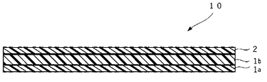
- FIG. 1 is a schematic cross-sectional view showing an example of the multilayer film for ultrasonic sealing of the present invention.
- FIG. 2 is a schematic cross-sectional view showing another example of the multilayer film for ultrasonic sealing of the present invention.
- FIG. 3A is a schematic cross-sectional view (No. 1) showing an example of an ultrasonic sealing device used for ultrasonic welding of the multilayer film for ultrasonic sealing of the present invention.
- FIG. 3B is a schematic cross-sectional view (No. 2) showing an example of an ultrasonic sealing device used for ultrasonic welding of the multilayer film for ultrasonic sealing of the present invention.
- FIG. 3C is a schematic cross-sectional view (No. 3) showing an example of an ultrasonic sealing device used for ultrasonic welding of the multilayer film for ultrasonic sealing of the present invention.
- FIG. 4 is a graph showing the results of measuring the sealing strength of the multilayer film for ultrasonic sealing in Examples.
- the ultrasonic sealing multilayer film of the present invention has at least a thermoplastic resin layer and a sealing layer, and is ultrasonically sealable.
- the thermoplastic resin layer contains a thermoplastic resin as a main resin component.
- the thermoplastic resin layer may be a single layer or multiple layers.
- Said thermoplastic layer may be a surface layer on which printing of the packaging film can be provided.
- thermoplastic resin is not particularly limited and can be appropriately selected from known thermoplastic resins depending on the intended purpose. Examples thereof include ⁇ -olefin resins, styrene resins, ester resins, and acrylic resins. Among these, the ⁇ -olefin resin is preferable because it can be made into a monomaterial.
- ⁇ -olefin resin examples include homopolymers of ⁇ -olefin monomers (polyethylene homopolymer, polypropylene homopolymer, etc.); copolymers mainly composed of ⁇ -olefin monomers (propylene-ethylene block copolymer polymer, propylene-ethylene random copolymer, ethylene-butene-1 copolymer, propylene-butene-1 copolymer, etc.). These may be used individually by 1 type, and may use 2 or more types together. Among these, ethylene homopolymers, propylene homopolymers, propylene-ethylene block copolymers, and propylene-ethylene random copolymers containing at least one of polyethylene and polypropylene are preferred.
- the content of the ⁇ -olefin monomer in the ⁇ -olefin resin is preferably 50 mol % to 100 mol %, more preferably 70 mol % to 100 mol %.
- the melt flow rate (MFR) of the thermoplastic resin is not particularly limited and can be appropriately selected according to the purpose. 50.0 g/10 minutes is preferred, 3.0 g/10 minutes to 45.0 g/10 minutes is more preferred, and 3.0 g/10 minutes to 12.0 g/10 minutes is even more preferred.
- the melt flow rate (MFR) is a value measured at 190° C. under a load of 2.16 kg (21.18 N) according to JISK7210.
- the density of the thermoplastic resin is not particularly limited and can be appropriately selected according to the purpose. 93 g/cm 3 is more preferred.
- the melting point of the thermoplastic resin is not particularly limited and can be appropriately selected according to the purpose.
- the melting point can be measured using a differential scanning calorimeter (DSC) (for example, DSC7020 manufactured by Hitachi High-Tech Science Co., Ltd.).
- DSC differential scanning calorimeter
- the sealing layer contains random polypropylene and ⁇ -olefin resin as main resin components.
- the random polypropylene is a random copolymer of 90% to 98% by mass of propylene and 10% to 2% by mass of ethylene and/or an ⁇ -olefin having 4 or more carbon atoms. Examples of the ⁇ -olefin having 4 or more carbon atoms include 1-butene.
- the random polypropylene may be used singly or in combination of two or more.
- the content of the random polypropylene is preferably 50% by mass or more and 95% by mass or less, more preferably 50% by mass or more and 70% by mass or less, relative to the total amount of the resin components contained in the seal layer.
- the melt flow rate (MFR) of the random polypropylene is not particularly limited and can be appropriately selected according to the purpose. 50.0 g/10 minutes is preferred, 3.0 g/10 minutes to 45.0 g/10 minutes is more preferred, and 3.0 g/10 minutes to 12.0 g/10 minutes is even more preferred.
- the density of the random polypropylene is not particularly limited and can be appropriately selected according to the purpose. /cm 3 is more preferred.
- the melting point of the random polypropylene is not particularly limited and can be appropriately selected according to the purpose, but is preferably 110°C to 160°C, more preferably 120°C to 140°C.
- the ⁇ -olefin resin contains at least a butene-based ⁇ -olefin resin and, if necessary, an ⁇ -olefin resin other than the butene-based ⁇ -olefin resin.
- the ⁇ -olefin resin is not particularly limited and can be appropriately selected depending on the intended purpose. -propylene copolymer, ethylene-butene-1 copolymer, propylene-butene-1 copolymer and the like. These may be used individually by 1 type, and may use 2 or more types together.
- the content of the ⁇ -olefin monomer in the ⁇ -olefin resin is preferably 50 mol % to 100 mol %, more preferably 70 mol % to 100 mol %.
- the melt flow rate (MFR) of the ⁇ -olefin resin other than the butene-based ⁇ -olefin resin is not particularly limited and can be appropriately selected according to the purpose. , preferably 1.0 g / 10 minutes to 50.0 g / 10 minutes, more preferably 2.0 g / 10 minutes to 45.0 g / 10 minutes, even more preferably 2.0 g / 10 minutes to 10.0 g / 10 minutes .
- the density of the ⁇ - olefin resin other than the butene - based ⁇ -olefin resin is not particularly limited and can be appropriately selected according to the purpose. 87 g/cm 3 to 0.90 g/cm 3 is more preferable.
- the melting point of the ⁇ -olefin resin other than the butene-based ⁇ -olefin resin is not particularly limited and can be appropriately selected according to the purpose.
- butene-based ⁇ -olefin resin-- The butene-based ⁇ -olefin resin is not particularly limited and can be appropriately selected according to the purpose. Examples include 1-butene copolymers and propylene-1-butene copolymers. Among these, a propylene-1-butene copolymer is preferred. These may be used individually by 1 type, and may use 2 or more types together.
- the content of the butene-1 monomer in the butene-based ⁇ -olefin resin is preferably 50 mol % to 100 mol %, more preferably 70 mol % to 100 mol %.
- the melt flow rate (MFR) of the butene-based ⁇ -olefin resin is not particularly limited and can be appropriately selected according to the purpose. 10 minutes to 50.0 g/10 minutes is preferred, 3.0 g/10 minutes to 45.0 g/10 minutes is more preferred, and 3.0 g/10 minutes to 12.0 g/10 minutes is even more preferred.
- the density of the butene - based ⁇ - olefin resin is not particularly limited and can be appropriately selected according to the purpose. 0.92 g/cm 3 is more preferred.
- the melting point of the butene-based ⁇ -olefin resin is not particularly limited and can be appropriately selected according to the purpose. More preferred.
- the content of the butene-based ⁇ -olefin resin is preferably 5% by mass or more and 50% by mass or less, more preferably 10% by mass or more and 50% by mass or less, based on the total amount of the resin components contained in the seal layer. It is more preferably 50% by mass or less, and particularly preferably 20% by mass or more and 50% by mass or less.
- the content is 5% by mass or more and 50% by mass or less, it is advantageous in terms of exhibiting ultrasonic sealing properties. Further, when the content is 20% by mass or more and 50% by mass or less, it is particularly advantageous in terms of ensuring uniform and stable ultrasonic sealing performance over the entire sealing length.
- the mass ratio (b2/b1) of the butene-based ⁇ -olefin resin (b2) to the random polypropylene (b1) in the seal layer is not particularly limited and can be appropriately selected depending on the purpose, but is 5/95. 50/50 is preferred, 10/90 to 50/50 is more preferred, 20/80 to 50/50 is even more preferred, and 30/70 to 50/50 is particularly preferred.
- the resin of the thermoplastic resin layer and the seal layer contains other components such as antioxidants, ultraviolet absorbers, antistatic agents, and lubricants (antiblocking agents, slip agents) commonly used in polyolefins. may be blended as appropriate.
- the thermoplastic resin layer in the multilayer film for ultrasonic sealing may be a single layer or a plurality of layers.
- the plurality of thermoplastic resin layers may have the same composition or different compositions.
- the thermoplastic resin layer is a single layer
- the multilayer film for ultrasonic sealing is a multilayer film laminated in the order of thermoplastic resin layer/seal layer.
- the thermoplastic resin layer is a plurality of layers
- the thermoplastic resin layer has a base layer that serves as a surface layer of the multilayer film for ultrasonic sealing and an intermediate layer (one to multiple layers).
- the multilayer film for ultrasonic sealing is a multilayer film laminated in the order of base layer (thermoplastic resin layer)/intermediate layer (thermoplastic resin layer)/seal layer.
- the multilayer film for ultrasonic sealing may be a coextrusion multilayer film in which each layer is extruded and laminated together, or may be a laminate film in which some layers are adhered and laminated.
- the adhesion method for laminating the additional base material layer is not particularly limited and can be appropriately selected according to the purpose. Examples thereof include dry lamination, wet lamination, non-solvent lamination and extrusion lamination.
- the multilayer film for ultrasonic sealing is basically transparent and has a smooth surface.
- the mixed resin layer on both sides or one side of the multilayer film for ultrasonic sealing may be subjected to a corona discharge treatment to impart printability.
- both sides or one side of the multilayer film for ultrasonic sealing may be embossed to give an aperture pattern such as a satin finish.
- the total thickness of the multilayer film for ultrasonic sealing is not particularly limited and can be appropriately selected according to the purpose. More preferably, the thickness is 90 ⁇ m or more.
- the average thickness of a single layer or each layer of the thermoplastic resin layer is not particularly limited and can be appropriately selected according to the purpose.
- the total average thickness of each layer is not particularly limited and can be appropriately selected according to the purpose.
- the thickness of the thermoplastic resin layer is not particularly limited and can be appropriately selected according to the purpose. (%) is preferably 90% or less, more preferably 20% to 90%, even more preferably 50% to 80%.
- the average thickness of the sealing layer is not particularly limited and can be appropriately selected according to the purpose, but is preferably 3 ⁇ m to 30 ⁇ m, more preferably 5 ⁇ m to 25 ⁇ m, and even more preferably 10 ⁇ m to 20 ⁇ m.
- the thickness of the seal layer is not particularly limited and can be appropriately selected according to the purpose. 10% or more is preferable, 20% or more is more preferable, and 30% or more is still more preferable. Also, it is preferably 10% or more and 50% or less, more preferably 20% or more and 50% or less, and even more preferably 30% or more and 50% or less. When the thickness is 10% or more, it is advantageous in terms of exhibiting ultrasonic sealability. Further, when the thickness is 20% or more, it is particularly advantageous in that uniform and stable ultrasonic sealing properties are ensured from 50% of the sealing length to the entire length.
- the heat of fusion measured by differential scanning calorimetry (DSC) in the multilayer film for ultrasonic sealing is preferably 65 mJ/mg or less from the viewpoint of uniform weldability by ultrasonic sealing.
- the amount of heat of fusion measured by differential scanning calorimetry (DSC) is the amount of heat of fusion in the first temperature rise, and is measured in the following procedure using, for example, a differential scanning calorimeter (manufactured by Hitachi High-Tech Science Co., Ltd., DSC7020). be able to.
- a multilayer film for ultrasonic sealing which is a target sample
- the sample container is placed on a holder unit, and set in an electric furnace.
- the sample is heated from 30° C. to 200° C. at a temperature increase rate of 10° C./min (first temperature increase), and the DSC curve is measured using a differential scanning calorimeter. From the obtained DSC curve, an analysis program for a differential scanning calorimeter is used to select the DSC curve at the time of the first temperature increase, and the heat of fusion [mJ/mg] of the target sample at the first temperature increase can be obtained. can.
- the method of sealing by ultrasonic waves is not particularly limited, and a known ultrasonic sealing method, a method using a known ultrasonic sealing device, or the like can be appropriately selected according to the purpose.
- the “ultrasonic seal” is a combination of an “ultrasonic horn” that transmits vibration energy by ultrasonic waves and a fixing jig “anvil” using ultrasonic vibration amplitude that converts electrical energy into mechanical energy. It is a technology in which a film to be joined is sandwiched in between, and frictional energy is generated uniformly at the interfaces of the film materials, resulting in instantaneous fusion and welding.
- the terms “ultrasonic sealing”, “ultrasonic welding”, “ultrasonic fusion welding”, and “ultrasonic fusion bonding” can be synonymous with each other.
- the ultrasonic horn may be arranged vertically above the object to be welded and the anvil, or horizontally with respect to the object to be welded and the anvil.
- Ultrasonic horns vibrate with ultrasonic waves, typically between 20 kHz and 40 kHz, to transfer energy under pressure, typically in the form of frictional heat, to the joints to be joined. Due to the frictional heat and pressure, a portion of at least one of the objects to be joined softens or melts, thereby joining the objects to be joined together.
- the "bonding object” is not particularly limited as long as it contains at least the multilayer film for ultrasonic sealing of the present invention, and can be appropriately selected according to the purpose.
- Two multilayer films may be arranged so that the seal layers are in contact with each other, and a series (one sheet) of the multilayer film for ultrasonic sealing may be folded so that the seal layers are in contact with each other.
- the ultrasonic sealing multilayer film and the thermoplastic resin film are arranged such that the sealing layer of the ultrasonic sealing multilayer film is in contact with the thermoplastic resin film.
- a laminate to be described later can be obtained by ultrasonically sealing the portions where the seal layers are in contact with each other and the portions where the seal layers are in contact with the thermoplastic resin film to form joints.
- the ultrasonic waves in the ultrasonic seal are not particularly limited, and elastic vibration waves (sound waves) having a high frequency that cannot be heard by human ears can be appropriately selected according to the purpose.
- the frequency of the ultrasonic waves is preferably 16 kHz or higher, more preferably 20 kHz or higher, and particularly preferably 20 kHz or higher and 40 kHz or lower.
- the conditions such as pressure, amplitude, welding time, and hold time in the ultrasonic sealing change according to the type of object to be joined, frequency, and combination of conditions, and cannot be univocally defined, but there are no particular restrictions. can be selected as appropriate depending on the purpose.
- the pressure means the pressing pressure of the ultrasonic horn against the object to be welded in the ultrasonic sealing device, and is expressed in units such as [Pa] (pascal), [MPa] (megapascal), and the like.
- the pressure is preferably 0.15 [MPa] to 0.3 [MPa], more preferably 0.25 [MPa] to 0.3 [MPa].
- the amplitude means the magnitude of ultrasonic vibration.
- the amplitude is preferably 20 ⁇ m or more and 50 ⁇ m or less, and more preferably 35 ⁇ m or more and 50 ⁇ m or less in order to have a uniform and stable seal strength.
- the welding time indicates the oscillation time of ultrasonic waves, and means the time during which the ultrasonic horn contacts and welds the object to be welded.
- the welding time is preferably 0.2 seconds or more and 1 second or less, more preferably 0.5 seconds or more and 1 second or less.
- the hold time means the holding time of the ultrasonic oscillator and the hardening time of the welded portion.
- the hold time is preferably 0.2 seconds or more and 1.0 seconds or less, more preferably 0.5 seconds or more and 1.0 seconds or less.
- Suitable examples of the ultrasonic sealing device include a continuous ultrasonic sealing type device, a device having a rotary ultrasonic horn, and the like.
- Such continuous ultrasonic sealing type devices are commonly known as "continuous ultrasonic fusion bonds".
- Continuous ultrasonic fusion bonding can generally be fed substantially continuously into an ultrasonic sealing device, and is used to substantially continuously seal objects to be bonded.
- the ultrasonic horn is usually fixed and the object to be welded moves underneath it.
- One type of continuous ultrasonic fusion bond uses a stationary horn and a rotating anvil face. During continuous ultrasonic fusion bonding, the object to be welded is pulled between the ultrasonic horn and the rotating anvil.
- the ultrasonic horn typically extends longitudinally toward the object to be joined, and vibrations are transmitted axially along the ultrasonic horn to the material.
- the ultrasonic horn In the device with a rotating ultrasonic horn, the ultrasonic horn is of rotary type, cylindrical and rotates about its longitudinal axis.
- the input vibration is in the axial direction of the ultrasonic horn and the output vibration is in the radial direction of the ultrasonic horn.
- the ultrasonic horn is placed in close proximity to the anvil, and the anvil is typically also rotatable such that the object to be welded passes between the cylindrical surfaces at a linear velocity substantially equal to the tangential velocity of the cylindrical surfaces. .
- ultrasonic seals examples include JP-A-2008-526552, JP-A-2010-195044, JP-A-2013-231249, JP-A-2015-16294, and US Pat. No. 5,976,316. and the disclosure of which is incorporated herein by reference.
- the laminate of the present invention includes at least the multilayer film for ultrasonic sealing of the present invention, and is a laminate obtained by arranging two sheets of the multilayer film for ultrasonic sealing so that the respective sealing layers are in contact with each other and sealing them by ultrasonic waves. It may be a laminate obtained by folding and arranging a series (one sheet) of the multilayer film for ultrasonic sealing so that the sealing layers are in contact with each other, and then sealing by ultrasonic waves, or A laminate obtained by arranging the multilayer film for ultrasonic sealing and a thermoplastic resin film so that the seal layer of the multilayer film for ultrasonic sealing is in contact with the thermoplastic resin film and sealing them by ultrasonic waves, good too.
- the laminate can be suitably used as a package.
- the package examples include packages for food such as western confectionery, snacks, bread, Japanese confectionery, and seasonings.
- the laminate can be made of a monomaterial and can be sealed by an ultrasonic seal capable of heating only the sealing surface, so that the width of the seal can be narrowed and the amount of material can be reduced.
- thermoplastic resin film The material of the thermoplastic resin film is not particularly limited and can be appropriately selected from known thermoplastic resins according to the purpose.
- ⁇ -olefin resin any of the ⁇ -olefin resins described for the thermoplastic resin layer can be appropriately employed.
- the ultrasonic sealing multilayer film 10 of the present invention is, for example, a multilayer film composed of a thermoplastic resin layer 1 and a sealing layer 2 and having two layers laminated, as shown in FIG. Further, as shown in FIG. 2, the multilayer film 10 for ultrasonic sealing of the present invention may have a plurality of thermoplastic resin layers, a thermoplastic resin layer (base layer) 1a, a thermoplastic resin layer ( It may be a multi-layer film consisting of an intermediate layer) 1b and a seal layer 2, which is laminated in the order of substrate layer/intermediate layer/seal layer.
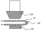
- FIG. 3A to 3C are schematic cross-sectional views showing an example of an ultrasonic sealing device used for ultrasonic welding of the multilayer film for ultrasonic sealing of the present invention.
- the ultrasonic sealing device 100 has an anvil 110 and an ultrasonic horn 120 facing the outer peripheral surface of the anvil 110 . Seal projections are formed in a predetermined seal pattern on the outer peripheral surface of the anvil 110, and the ultrasonic horn 120 moves in the direction of the arrow in FIG. You can hold the joint target.
- the object to be joined passed between the anvil 110 and the ultrasonic horn 120 may be, for example, two layers of the ultrasonic sealing multilayer film 10 (FIG. 3A).
- It may be a plastic resin film in two layers (not shown), or a single ultrasonic sealing multilayer film 10 that is hooked on a metal rod 130 and folded into two layers.
- Good Fig. 3B
- a portion of the object to be joined sandwiched between the seal projection on the outer peripheral surface of the anvil 110 and the ultrasonic horn 120 is melt-sealed by frictional heat generated by ultrasonic vibration transmitted from the ultrasonic horn 120, thereby ultrasonically sealing.
- a laminate 50 containing at least the multi-layer film 10 is produced (see FIG. 3C).
- the ultrasonic sealing device transmits vibration energy to the object to be welded from the tip of an ultrasonic horn in contact with the object to be welded, and welds the object to be welded by frictional heat.
- the seal projections on the outer peripheral surface of the anvil 110 have a shape of 200 mm ⁇ 2 mm, thereby manufacturing the welded laminate 50 with a seal length of 200 mm ⁇ seal width of 2 mm. .
- Base layer (A) 70 parts of a propylene-ethylene block copolymer (density: 0.91 g/cm 3 , MFR: 7.0 g/10 min) (hereinafter referred to as COPP (1)), and a propylene-ethylene block copolymer A mixture with 30 parts of coalescence (density 0.91 g/cm 3 , MFR 4.0 g/10 min) (hereinafter referred to as COPP (2)).
- COPP (1) propylene-ethylene block copolymer
- COPP (2) propylene-ethylene block copolymer A mixture with 30 parts of coalescence
- Intermediate layer (C) 50 parts of a propylene-ethylene random copolymer (density of 0.90 g/cm 3 , MFR 6.0 g/10 min) (hereinafter referred to as COPP (3)) and 50 parts of COPP (1) a mixture of Seal layer (B): 76 parts of COPP (3), propylene-1-butene copolymer (density 0.90 g/cm 3 , MFR 4.0 g/10 min, melting point 100° C.) (hereinafter referred to as BP (1) .) 24 parts.
- a resin mixture forming each layer is supplied to each of three extruders, and the ratio of the average thickness of each layer of the laminated film formed by the base layer (A) / intermediate layer (C) / seal layer (B) is , 26%: 50%: 24%, co-extruded from a T die at an extrusion temperature of 250 ° C., cooled with a water-cooled metal cooling roll at 40 ° C., and a laminated film with a total thickness of 40 ⁇ m
- Example 1- A multilayer film for ultrasonic sealing of No. 1 was molded.
- Example 1-2 to 1-4 Examples 1-2 to 1-1 were carried out in the same manner as in Example 1-1, except that the thickness ratio of the seal layer (B) was changed as shown in Table 1 while the total thickness was 40 ⁇ m. A multi-layer film for ultrasonic sealing of No. -4 was produced and evaluated. Table 1 shows the results.
- Example 1-1 Example 1-1 except that, as shown in Table 1, the resin composition of the seal layer (B) was changed to a mixture of 68 parts of COPP (3) and 32 parts of BP (1).
- a multilayer film for ultrasonic sealing of Examples 1-5 was produced in the same manner as in and evaluated. Table 1 shows the results.
- Example 1-6 Example 1-1 except that, as shown in Table 1, the resin composition of the seal layer (B) was changed to a mixture of 60 parts of COPP (3) and 40 parts of BP (1). A multilayer film for ultrasonic sealing of Example 1-6 was produced in the same manner as in and evaluated. Table 1 shows the results.
- Example 1--7 the BP (1) of the sealing layer (B) was a propylene-1-butene copolymer (density 0.9 g/cm 3 , MFR 4.0 g/10 min, melting point 58°C) (hereinafter referred to as BP (A multilayer film for ultrasonic sealing of Example 1-7 was produced and evaluated in the same manner as in Example 1-1, except that it was changed to 2). Table 1 shows the results.
- Comparative Example 1 was prepared in the same manner as in Example 1-1, except that the resin composition of the sealing layer (B) was changed to 100 parts of COPP (3) (excluding BP (1)). A multilayer film for ultrasonic sealing was produced and evaluated. Table 1 shows the results.
- Example 2-1 A multilayer film for ultrasonic sealing of Example 2-1 was produced and evaluated in the same manner as in Example 1-1, except that the total thickness of 40 ⁇ m was changed to 30 ⁇ m. Table 2 shows the results.
- Examples 2-2 to 2--7 For ultrasonic sealing of Examples 2-2 to 2-7 in the same manner as in Examples 1-2 to 1-7, except that the total thickness of 40 ⁇ m was changed to 30 ⁇ m in Examples 1-2 to 1-7. A multilayer film was produced and evaluated. Table 2 shows the results.
- Comparative Example 2 Comparative Example 2 was prepared in the same manner as in Example 2-1, except that the resin composition of the sealing layer (B) was changed to 100 parts of COPP (3) (excluding BP (1)). A multilayer film for ultrasonic sealing was produced and evaluated. Table 2 shows the results.
- Example 3-1 A multilayer film for ultrasonic sealing of Example 3-1 was produced in the same manner as in Example 1-1, except that the total thickness of 40 ⁇ m was changed to 50 ⁇ m. Table 3 shows the results.
- Example 3-1 in addition to the evaluation of the ultrasonic sealing property performed in Example 1-1, additional evaluation was performed by changing the parameter conditions of the ultrasonic sealing device. Specifically, the pressure is reduced from 0.30 [MPa] to 0.25 [MPa], 0.20 [MPa], and 0.15 [MPa], and the amplitude is reduced from 50 [ ⁇ m] The conditions were changed to 35 [ ⁇ m] and 20 [ ⁇ m], respectively. It was evaluated according to the evaluation criteria for ultrasonic sealability in Example 1-1. Table 4 shows the results.
- the DSC curve at the time of the first heating was selected using a differential scanning calorimeter analysis program, and the heat of fusion [mJ/mg] of the target sample at the first heating was determined.
- Examples 3-2 to 3--7 For ultrasonic sealing of Examples 3-2 to 3-7 in the same manner as in Examples 1-2 to 1-7, except that the total thickness of 40 ⁇ m was changed to 50 ⁇ m in Examples 1-2 to 1-7. A multilayer film was produced and evaluated in the same manner as in Example 3-1. The results are shown in Tables 3-4 and FIG.
- Comparative Example 3 Comparative Example 3 was prepared in the same manner as in Example 3-1, except that the resin composition of the sealing layer (B) was changed to 100 parts of COPP (3) (excluding BP (1)). A multilayer film for ultrasonic sealing was produced and evaluated. The results are shown in Tables 3-4.
- Example 2-7 it was found that when the thickness of the seal layer is 24% or more of the total thickness, the ultrasonic sealability is ensured over the entire seal length. From the results in Tables 1 to 3, it was found that the ultrasonic sealing strength increased when the total thickness of the multilayer film for ultrasonic sealing was 40 ⁇ m or more, and the ultrasonic sealing property was secured from 50% or more of the sealing length to the entire length. Further, from the results in Tables 1, 3 and FIG. 4, when the total thickness of the multilayer film for ultrasonic sealing is 50 ⁇ m, the ultrasonic sealing strength is generally increased compared to when the total thickness is 40 ⁇ m, and the influence between the parameters can be seen. I found out I could't.
- the MFR, density, and melting point of each resin used in the examples are shown below.
Landscapes
- Lining Or Joining Of Plastics Or The Like (AREA)
- Laminated Bodies (AREA)
Abstract
Provided is a multilayer film for ultrasonic sealing that is applicable to monomaterialization and whereby ultrasonic welding is possible, and that can have a narrow sealing width, and uniform and stable ultrasonic sealing strength, the multilayer film for ultrasonic sealing being characterized by having at least a thermoplastic resin layer containing a thermoplastic resin, and a sealing layer containing a random polypropylene and an α olefin resin, the α olefin resin containing a butene-based α olefin resin, and the multilayer film being capable of sealing by ultrasonic waves. Also provided is a laminate in which the multilayer film for ultrasonic sealing and a thermoplastic resin film are sealed by ultrasonic waves.
Description
本発明は、超音波シール用多層フィルム、及び積層体に関する。
The present invention relates to a multilayer film for ultrasonic sealing and a laminate.
洋菓子、スナック等の食品用包装フィルムにおいて、リサイクルを促進して環境負荷を低減するため、モノマテリアル(単一素材)化が進んでいる。従来の異素材の多層ラミネート構成(例えば、延伸ポリエチレンテレフタレートOPET/無延伸ポリプロピレンCPPの多層フィルム)に対し、モノマテリアル化に対応するためには、延伸ポリプロピレンOPP/無延伸ポリプロピレンCPPのような多層フィルムが求められている。
The use of mono-materials (single materials) is progressing in order to promote recycling and reduce the environmental impact of food packaging films such as Western confectionery and snacks. Multilayer films such as oriented polypropylene OPP / non-oriented polypropylene CPP have been developed in order to respond to monomaterialization, as opposed to the conventional multi-layer laminate structure of different materials (e.g., oriented polyethylene terephthalate OPET / non-oriented polypropylene CPP multi-layer film). is required.
しかしながら、従来のモノマテリアル化に対応したOPP/CPPからなる多層フィルムでは、素材間の耐熱性が異なるため、多層フィルムの表面が耐熱低下し、包装適性の低下が懸念されるという問題点がある。
However, the multilayer film made of OPP/CPP, which is compatible with conventional mono-materialization, has a problem that heat resistance of the surface of the multilayer film decreases due to the difference in heat resistance between the materials, and there is concern that the packaging suitability may decrease. .
一方、シール面のみ加熱可能な超音波を用い、超音波シール可能な多層フィルムが検討されている。これまでに、超音波溶接によっても強固に溶接することができる積層フィルムとして、エチレン-アルキル(メタ)アクリレート共重合体などのエチレン-極性単量体共重合体を中心層とし、その両面にランダムポリプロピレンとαオレフィン系エラストマーの混合樹脂からなる表面層を形成させ、中心層と表面層の間に非晶質ポリオレフィン層を介在させた積層フィルムが提案されている(例えば、特許文献1参照)。
On the other hand, a multilayer film that can be ultrasonically sealed using ultrasonic waves that can heat only the sealing surface is being studied. So far, as a laminated film that can be strongly welded even by ultrasonic welding, a central layer is an ethylene-polar monomer copolymer such as an ethylene-alkyl (meth)acrylate copolymer, and random A laminated film has been proposed in which a surface layer made of a mixed resin of polypropylene and an α-olefin elastomer is formed, and an amorphous polyolefin layer is interposed between the central layer and the surface layer (see, for example, Patent Document 1).
しかしながら、ポリプロピレンを用いてモノマテリアル化に対応した多層フィルムでは、素材間の耐熱性が異なるため、超音波シールした場合に均一かつ安定なシール強度を得ることが困難であった。また、超音波シールに適した前記提案の積層フィルムでは、エチレン-極性単量体共重合体を含み、モノマテリアル化に対応できていない。したがって、モノマテリアル化に対応でき、かつ超音波シールに適した多層フィルムの樹脂構成が求められている。
However, with multilayer films that use polypropylene to support monomaterialization, it is difficult to obtain uniform and stable sealing strength when ultrasonically sealed due to differences in heat resistance between materials. Moreover, the laminated film proposed above, which is suitable for ultrasonic sealing, contains an ethylene-polar monomer copolymer and cannot be made into a monomaterial. Therefore, there is a demand for a multilayer film resin structure that can be used as a monomaterial and is suitable for ultrasonic sealing.
本発明は、前記従来における諸問題を解決し、以下の目的を達成することを課題とする。即ち、本発明は、モノマテリアル化に対応でき、超音波溶接が可能であり、シール幅が狭く均一かつ安定な超音波シール強度を有することができる超音波シール用多層フィルムを提供することを目的とする。
The object of the present invention is to solve the above-mentioned conventional problems and to achieve the following objectives. That is, it is an object of the present invention to provide a multilayer film for ultrasonic sealing that can be applied to a monomaterial, can be ultrasonically welded, and has a narrow sealing width and uniform and stable ultrasonic sealing strength. and
本発明は、本発明者らによる前記知見に基づくものであり、前記課題を解決するための手段としては、以下の通りである。即ち、
<1> 熱可塑性樹脂を含有する熱可塑性樹脂層と、
ランダムポリプロピレン及びαオレフィン樹脂を含有するシール層と、を少なくとも有し、
前記αオレフィン樹脂が、ブテン系αオレフィン樹脂を含有し、
超音波によりシール可能であることを特徴とする超音波シール用多層フィルムである。
<2> 前記シール層における前記ランダムポリプロピレンの含有量が、50質量%以上95質量%以下である前記<1>に記載の超音波シール用多層フィルムである。
<3> 前記シール層における前記ブテン系αオレフィン樹脂の含有が、20質量%以上50質量%以下である前記<1>から<2>のいずれかに記載の超音波シール用多層フィルムである。
<4> 前記シール層の厚みが、20%以上である前記<1>から<3>のいずれかに記載の超音波シール用多層フィルムである。
<5> 総厚みが40μm以上である前記<1>から<4>のいずれかに記載の超音波シール用多層フィルムである。
<6> 示差走査熱量測定によって測定される融解熱量が65mJ/mg以下である前記<1>から<5>のいずれかに記載の超音波シール用多層フィルムである。
<7> 前記熱可塑性樹脂が、ポリエチレン、及びポリプロピレンの少なくともいずれかを含有する前記<1>から<6>のいずれかに記載の超音波シール用多層フィルムである。
<8> 前記<1>から<7>のいずれかに記載の超音波シール用多層フィルムと、熱可塑性樹脂フィルムとを超音波によりシールした積層体である。 The present invention is based on the above findings by the present inventors, and means for solving the above problems are as follows. Namely
<1> a thermoplastic resin layer containing a thermoplastic resin;
At least a seal layer containing random polypropylene and an α-olefin resin,
The α-olefin resin contains a butene-based α-olefin resin,
The multilayer film for ultrasonic sealing is characterized in that it can be sealed by ultrasonic waves.
<2> The multilayer film for ultrasonic sealing according to <1>, wherein the content of the random polypropylene in the seal layer is 50% by mass or more and 95% by mass or less.
<3> The multilayer film for ultrasonic sealing according to any one of <1> and <2>, wherein the seal layer contains the butene-based α-olefin resin in an amount of 20% by mass or more and 50% by mass or less.
<4> The multilayer film for ultrasonic sealing according to any one of <1> to <3>, wherein the sealing layer has a thickness of 20% or more.
<5> The multilayer film for ultrasonic sealing according to any one of <1> to <4>, having a total thickness of 40 μm or more.
<6> The multilayer film for ultrasonic sealing according to any one of <1> to <5>, wherein the heat of fusion measured by differential scanning calorimetry is 65 mJ/mg or less.
<7> The multilayer film for ultrasonic sealing according to any one of <1> to <6>, wherein the thermoplastic resin contains at least one of polyethylene and polypropylene.
<8> A laminate obtained by ultrasonically sealing the multilayer film for ultrasonic sealing according to any one of <1> to <7> and a thermoplastic resin film.
本発明によれば、従来における前記諸問題を解決し、前記目的を達成することができ、モノマテリアル化に対応でき、超音波溶接が可能であり、シール幅が狭く均一かつ安定な超音波シール強度を有することができる超音波シール用多層フィルムを提供することができる。
According to the present invention, the above-mentioned problems in the conventional art can be solved, the above-mentioned objects can be achieved, it is possible to deal with monomaterialization, ultrasonic welding is possible, and a uniform and stable ultrasonic seal with a narrow seal width A multilayer film for ultrasonic sealing can be provided that can have strength.
(超音波シール用多層フィルム)
本発明の超音波シール用多層フィルムは、熱可塑性樹脂層と、シール層とを少なくとも有し、超音波によりシール可能である超音波シール用多層フィルムである。 (multilayer film for ultrasonic sealing)
The ultrasonic sealing multilayer film of the present invention has at least a thermoplastic resin layer and a sealing layer, and is ultrasonically sealable.
本発明の超音波シール用多層フィルムは、熱可塑性樹脂層と、シール層とを少なくとも有し、超音波によりシール可能である超音波シール用多層フィルムである。 (multilayer film for ultrasonic sealing)
The ultrasonic sealing multilayer film of the present invention has at least a thermoplastic resin layer and a sealing layer, and is ultrasonically sealable.
<熱可塑性樹脂層>
前記熱可塑性樹脂層は、熱可塑性樹脂を主たる樹脂成分として含有する。
前記熱可塑性樹脂層は、単層であってもよく、複数の層であってもよい。
前記熱可塑性樹脂層は、包装用フィルムの印刷を設けることができる表面層であってもよい。 <Thermoplastic resin layer>
The thermoplastic resin layer contains a thermoplastic resin as a main resin component.
The thermoplastic resin layer may be a single layer or multiple layers.
Said thermoplastic layer may be a surface layer on which printing of the packaging film can be provided.
-熱可塑性樹脂-
前記熱可塑性樹脂としては、特に制限はなく目的に応じて公知の熱可塑性樹脂を適宜選択することができ、例えば、αオレフィン樹脂、スチレン樹脂、エステル樹脂、アクリル樹脂などが挙げられる。これらの中でも、モノマテリアル化できる点から、αオレフィン樹脂が好ましい。
前記αオレフィン樹脂としては、例えば、αオレフィン単量体の単重合体(ポリエチレン単重合体、ポリプロピレン単重合体等);αオレフィン単量体を主成分とした共重合体(プロピレン-エチレンブロック共重合体、プロピレン-エチレンランダム共重合体、エチレン-ブテン-1共重合体、プロピレン-ブテン-1共重合体等)などが挙げられる。これらは、1種単独で使用してもよく、2種類以上を併用してもよい。これらの中でも、ポリエチレン、及びポリプロピレンの少なくともいずれかを含有する、エチレン単重合体、プロピレン単重合体、プロピレン-エチレンブロック共重合体、プロピレン-エチレンランダム共重合体が好ましい。
前記αオレフィン樹脂中のαオレフィン単量体の含有量としては、50モル%~100モル%が好ましく、70モル%~100モル%がより好ましい。 -Thermoplastic resin-
The thermoplastic resin is not particularly limited and can be appropriately selected from known thermoplastic resins depending on the intended purpose. Examples thereof include α-olefin resins, styrene resins, ester resins, and acrylic resins. Among these, the α-olefin resin is preferable because it can be made into a monomaterial.
Examples of the α-olefin resin include homopolymers of α-olefin monomers (polyethylene homopolymer, polypropylene homopolymer, etc.); copolymers mainly composed of α-olefin monomers (propylene-ethylene block copolymer polymer, propylene-ethylene random copolymer, ethylene-butene-1 copolymer, propylene-butene-1 copolymer, etc.). These may be used individually by 1 type, and may use 2 or more types together. Among these, ethylene homopolymers, propylene homopolymers, propylene-ethylene block copolymers, and propylene-ethylene random copolymers containing at least one of polyethylene and polypropylene are preferred.
The content of the α-olefin monomer in the α-olefin resin is preferably 50 mol % to 100 mol %, more preferably 70 mol % to 100 mol %.
前記熱可塑性樹脂のメルトフローレート(MFR)としては、特に制限はなく目的に応じて適宜選択することができるが、温度190℃、及び荷重2.16kgの測定条件において、1.0g/10分間~50.0g/10分間が好ましく、3.0g/10分間~45.0g/10分間がより好ましく、3.0g/10分間~12.0g/10分間が更に好ましい。
ここで、前記メルトフローレート(MFR)は、JISK7210に準拠して、190℃、荷重2.16kg(21.18N)で測定した値である。 The melt flow rate (MFR) of the thermoplastic resin is not particularly limited and can be appropriately selected according to the purpose. 50.0 g/10 minutes is preferred, 3.0 g/10 minutes to 45.0 g/10 minutes is more preferred, and 3.0 g/10 minutes to 12.0 g/10 minutes is even more preferred.
Here, the melt flow rate (MFR) is a value measured at 190° C. under a load of 2.16 kg (21.18 N) according to JISK7210.
前記熱可塑性樹脂の密度としては、特に制限はなく目的に応じて適宜選択することができるが、0.89g/cm3~0.96g/cm3が好ましく、0.89g/cm3~0.93g/cm3がより好ましい。
The density of the thermoplastic resin is not particularly limited and can be appropriately selected according to the purpose. 93 g/cm 3 is more preferred.
前記熱可塑性樹脂の融点としては、特に制限はなく目的に応じて適宜選択することができるが、110℃~170℃が好ましく、120℃~160℃がより好ましい。前記融点は、示差走査熱量計(DSC)(例えば、株式会社日立ハイテクサイエンス製、DSC7020)を用いて測定することができる。
The melting point of the thermoplastic resin is not particularly limited and can be appropriately selected according to the purpose. The melting point can be measured using a differential scanning calorimeter (DSC) (for example, DSC7020 manufactured by Hitachi High-Tech Science Co., Ltd.).
<シール層>
前記シール層は、ランダムポリプロピレン及びαオレフィン樹脂を主たる樹脂成分として含有する。 <Seal layer>
The sealing layer contains random polypropylene and α-olefin resin as main resin components.
前記シール層は、ランダムポリプロピレン及びαオレフィン樹脂を主たる樹脂成分として含有する。 <Seal layer>
The sealing layer contains random polypropylene and α-olefin resin as main resin components.
-ランダムポリプロピレン-
前記ランダムポリプロピレンとは、プロピレン90質量%~98質量%とエチレン及び/又は炭素数4以上のα-オレフィン10質量%~2質量%とのランダム共重合体である。前記炭素数4以上のα-オレフィンとしては、例えば、1-ブテンなどが挙げられる。前記ランダムポリプロピレンは、1種単独で使用してもよく、2種類以上を併用してもよい。 - Random Polypropylene -
The random polypropylene is a random copolymer of 90% to 98% by mass of propylene and 10% to 2% by mass of ethylene and/or an α-olefin having 4 or more carbon atoms. Examples of the α-olefin having 4 or more carbon atoms include 1-butene. The random polypropylene may be used singly or in combination of two or more.
前記ランダムポリプロピレンの含有量としては、前記シール層に含まれる樹脂成分の総量に対して、50質量%以上95質量%以下が好ましく、50質量%以上70質量%以下がより好ましい。
The content of the random polypropylene is preferably 50% by mass or more and 95% by mass or less, more preferably 50% by mass or more and 70% by mass or less, relative to the total amount of the resin components contained in the seal layer.
前記ランダムポリプロピレンのメルトフローレート(MFR)としては、特に制限はなく目的に応じて適宜選択することができるが、温度190℃、及び荷重2.16kgの測定条件において、1.0g/10分間~50.0g/10分間が好ましく、3.0g/10分間~45.0g/10分間がより好ましく、3.0g/10分間~12.0g/10分間が更に好ましい。
The melt flow rate (MFR) of the random polypropylene is not particularly limited and can be appropriately selected according to the purpose. 50.0 g/10 minutes is preferred, 3.0 g/10 minutes to 45.0 g/10 minutes is more preferred, and 3.0 g/10 minutes to 12.0 g/10 minutes is even more preferred.
前記ランダムポリプロピレンの密度としては、特に制限はなく目的に応じて適宜選択することができるが、0.89g/cm3~0.93g/cm3が好ましく、0.90g/cm3~0.92g/cm3がより好ましい。
The density of the random polypropylene is not particularly limited and can be appropriately selected according to the purpose. /cm 3 is more preferred.
前記ランダムポリプロピレンの融点としては、特に制限はなく目的に応じて適宜選択することができるが、110℃~160℃が好ましく、120℃~140℃がより好ましい。
The melting point of the random polypropylene is not particularly limited and can be appropriately selected according to the purpose, but is preferably 110°C to 160°C, more preferably 120°C to 140°C.
-αオレフィン樹脂-
前記αオレフィン樹脂は、少なくともブテン系αオレフィン樹脂を含有し、更に必要に応じて、ブテン系αオレフィン樹脂以外のαオレフィン樹脂を含有する。
前記αオレフィン樹脂としては、特に制限はなく目的に応じて適宜選択することができ、例えば、エチレン、プロピレン等のαオレフィン単量体の単重合体、αオレフィン単量体を主成分としたエチレン-プロピレン共重合体、エチレン-ブテン-1共重合体又はプロピレン-ブテン-1共重合体などが挙げられる。これらは、1種単独で使用してもよく、2種類以上を併用してもよい。
前記αオレフィン樹脂中のαオレフィン単量体の含有量としては、50モル%~100モル%が好ましく、70モル%~100モル%がより好ましい。 -α olefin resin-
The α-olefin resin contains at least a butene-based α-olefin resin and, if necessary, an α-olefin resin other than the butene-based α-olefin resin.
The α-olefin resin is not particularly limited and can be appropriately selected depending on the intended purpose. -propylene copolymer, ethylene-butene-1 copolymer, propylene-butene-1 copolymer and the like. These may be used individually by 1 type, and may use 2 or more types together.
The content of the α-olefin monomer in the α-olefin resin is preferably 50 mol % to 100 mol %, more preferably 70 mol % to 100 mol %.
前記ブテン系αオレフィン樹脂以外のαオレフィン樹脂のメルトフローレート(MFR)としては、特に制限はなく目的に応じて適宜選択することができるが、温度190℃、及び荷重2.16kgの測定条件において、1.0g/10分間~50.0g/10分間が好ましく、2.0g/10分間~45.0g/10分間がより好ましく、2.0g/10分間~10.0g/10分間が更に好ましい。
The melt flow rate (MFR) of the α-olefin resin other than the butene-based α-olefin resin is not particularly limited and can be appropriately selected according to the purpose. , preferably 1.0 g / 10 minutes to 50.0 g / 10 minutes, more preferably 2.0 g / 10 minutes to 45.0 g / 10 minutes, even more preferably 2.0 g / 10 minutes to 10.0 g / 10 minutes .
前記ブテン系αオレフィン樹脂以外のαオレフィン樹脂の密度としては、特に制限はなく目的に応じて適宜選択することができるが、0.85g/cm3~0.96g/cm3が好ましく、0.87g/cm3~0.90g/cm3がより好ましい。
The density of the α - olefin resin other than the butene - based α-olefin resin is not particularly limited and can be appropriately selected according to the purpose. 87 g/cm 3 to 0.90 g/cm 3 is more preferable.
前記ブテン系αオレフィン樹脂以外のαオレフィン樹脂の融点としては、特に制限はなく目的に応じて適宜選択することができるが、40℃~120℃が好ましく、50℃~100℃がより好ましい。
The melting point of the α-olefin resin other than the butene-based α-olefin resin is not particularly limited and can be appropriately selected according to the purpose.
--ブテン系αオレフィン樹脂--
前記ブテン系αオレフィン樹脂としては、特に制限はなく目的に応じて適宜選択することができ、例えば、ブテン-1単量体の単重合体、ブテン-1単量体を主成分としたエチレン-1-ブテン共重合体又はプロピレン-1-ブテン共重合体などが挙げられる。これらの中でも、プロピレン-1-ブテン共重合体が好ましい。これらは、1種単独で使用してもよく、2種類以上を併用してもよい。
前記ブテン系αオレフィン樹脂中のブテン-1単量体の含有量としては、50モル%~100モル%が好ましく、70モル%~100モル%がより好ましい。 --butene-based α-olefin resin--
The butene-based α-olefin resin is not particularly limited and can be appropriately selected according to the purpose. Examples include 1-butene copolymers and propylene-1-butene copolymers. Among these, a propylene-1-butene copolymer is preferred. These may be used individually by 1 type, and may use 2 or more types together.
The content of the butene-1 monomer in the butene-based α-olefin resin is preferably 50 mol % to 100 mol %, more preferably 70 mol % to 100 mol %.
前記ブテン系αオレフィン樹脂のメルトフローレート(MFR)としては、特に制限はなく目的に応じて適宜選択することができるが、温度190℃、及び荷重2.16kgの測定条件において、1.0g/10分間~50.0g/10分間が好ましく、3.0g/10分間~45.0g/10分間がより好ましく、3.0g/10分間~12.0g/10分間が更に好ましい。
The melt flow rate (MFR) of the butene-based α-olefin resin is not particularly limited and can be appropriately selected according to the purpose. 10 minutes to 50.0 g/10 minutes is preferred, 3.0 g/10 minutes to 45.0 g/10 minutes is more preferred, and 3.0 g/10 minutes to 12.0 g/10 minutes is even more preferred.
前記ブテン系αオレフィン樹脂の密度としては、特に制限はなく目的に応じて適宜選択することができるが、0.89g/cm3~0.96g/cm3が好ましく、0.89g/cm3~0.92g/cm3がより好ましい。
The density of the butene - based α - olefin resin is not particularly limited and can be appropriately selected according to the purpose. 0.92 g/cm 3 is more preferred.
前記ブテン系αオレフィン樹脂の融点としては、特に制限はなく目的に応じて適宜選択することができるが、50℃~120℃が好ましく、50℃~110℃がより好ましく、50℃~80℃が更に好ましい。
The melting point of the butene-based α-olefin resin is not particularly limited and can be appropriately selected according to the purpose. More preferred.
前記ブテン系αオレフィン樹脂の含有量としては、前記シール層に含まれる樹脂成分の総量に対して、5質量%以上50質量%以下が好ましく、10質量%以上50質量%以下がより好ましく、15質量%以上50質量%以下が更に好ましく、20質量%以上50質量%以下が特に好ましい。
前記含有量が5質量%以上50質量%以下であると、超音波シール性が発現する点で有利である。また、前記含有量が20質量%以上50質量%以下であると、シール長の全長で均一かつ安定な超音波シール性が担保される点で特に有利である。 The content of the butene-based α-olefin resin is preferably 5% by mass or more and 50% by mass or less, more preferably 10% by mass or more and 50% by mass or less, based on the total amount of the resin components contained in the seal layer. It is more preferably 50% by mass or less, and particularly preferably 20% by mass or more and 50% by mass or less.
When the content is 5% by mass or more and 50% by mass or less, it is advantageous in terms of exhibiting ultrasonic sealing properties. Further, when the content is 20% by mass or more and 50% by mass or less, it is particularly advantageous in terms of ensuring uniform and stable ultrasonic sealing performance over the entire sealing length.
前記シール層における前記ランダムポリプロピレン(b1)に対する前記ブテン系αオレフィン樹脂(b2)の質量比(b2/b1)としては、特に制限はなく目的に応じて適宜選択することができるが、5/95~50/50が好ましく、10/90~50/50がより好ましく、20/80~50/50が更に好ましく、30/70~50/50が特に好ましい。
The mass ratio (b2/b1) of the butene-based α-olefin resin (b2) to the random polypropylene (b1) in the seal layer is not particularly limited and can be appropriately selected depending on the purpose, but is 5/95. 50/50 is preferred, 10/90 to 50/50 is more preferred, 20/80 to 50/50 is even more preferred, and 30/70 to 50/50 is particularly preferred.
<その他の成分>
前記熱可塑性樹脂層、及び前記シール層の樹脂には、その他の成分として、ポリオレフィンに汎用される酸化防止剤、紫外線吸収剤、帯電防止剤、滑剤(ブロッキング防止剤、スリップ剤)などの配合剤を適宜配合してもよい。 <Other ingredients>
The resin of the thermoplastic resin layer and the seal layer contains other components such as antioxidants, ultraviolet absorbers, antistatic agents, and lubricants (antiblocking agents, slip agents) commonly used in polyolefins. may be blended as appropriate.
[超音波シール用多層フィルムの層構成]
前記超音波シール用多層フィルムにおける前記熱可塑性樹脂層は、単層であってもよく、複数の層であってもよい。複数の前記熱可塑性樹脂層は、互いに同じ組成であってもよく、異なる組成であってもよい。
前記熱可塑性樹脂層が単層である場合、前記超音波シール用多層フィルムは、熱可塑性樹脂層/シール層の順で積層される多層フィルムである。
前記熱可塑性樹脂層が複数の層である場合、前記熱可塑性樹脂層は、前記超音波シール用多層フィルムの表面層となる基材層と、(1層~複数層の)中間層とを有し、前記超音波シール用多層フィルムは、基材層(熱可塑性樹脂層)/中間層(熱可塑性樹脂層)/シール層の順で積層される多層フィルムである。
前記超音波シール用多層フィルムは、各層が共に押し出されて積層される共押出多層フィルムであってもよく、一部の層を接着して積層されるラミネートフィルムであってもよい。
前記追加基材層をラミネートする際の接着方法としては、特に制限はなく目的に応じて適宜選択することができ、例えば、ドライラミネーション、ウエットラミネーション、ノンソルベントラミネーション、押出ラミネーションなどが挙げられる。 [Layer structure of multilayer film for ultrasonic sealing]
The thermoplastic resin layer in the multilayer film for ultrasonic sealing may be a single layer or a plurality of layers. The plurality of thermoplastic resin layers may have the same composition or different compositions.
When the thermoplastic resin layer is a single layer, the multilayer film for ultrasonic sealing is a multilayer film laminated in the order of thermoplastic resin layer/seal layer.
When the thermoplastic resin layer is a plurality of layers, the thermoplastic resin layer has a base layer that serves as a surface layer of the multilayer film for ultrasonic sealing and an intermediate layer (one to multiple layers). The multilayer film for ultrasonic sealing is a multilayer film laminated in the order of base layer (thermoplastic resin layer)/intermediate layer (thermoplastic resin layer)/seal layer.
The multilayer film for ultrasonic sealing may be a coextrusion multilayer film in which each layer is extruded and laminated together, or may be a laminate film in which some layers are adhered and laminated.
The adhesion method for laminating the additional base material layer is not particularly limited and can be appropriately selected according to the purpose. Examples thereof include dry lamination, wet lamination, non-solvent lamination and extrusion lamination.
前記超音波シール用多層フィルムは、基本的には透明で、表面平滑である。前記超音波シール用多層フィルムの両面又は片面の混合樹脂層にコロナ放電処理して印刷特性を持たせてもよい。また、前記超音波シール用多層フィルムの両面又は片面にエンボス処理して梨地などの絞模様を付与してもよい。
The multilayer film for ultrasonic sealing is basically transparent and has a smooth surface. The mixed resin layer on both sides or one side of the multilayer film for ultrasonic sealing may be subjected to a corona discharge treatment to impart printability. In addition, both sides or one side of the multilayer film for ultrasonic sealing may be embossed to give an aperture pattern such as a satin finish.
前記超音波シール用多層フィルムの総厚みとしては、特に制限はなく目的に応じて適宜選択することができるが、均一かつ安定な超音波シール強度が担保される点で、40μm以上が好ましく、40μm以上90μm以下がより好ましい。
The total thickness of the multilayer film for ultrasonic sealing is not particularly limited and can be appropriately selected according to the purpose. More preferably, the thickness is 90 μm or more.
前記熱可塑性樹脂層の単層又は各層の平均厚みとしては、特に制限はなく目的に応じて適宜選択することができるが、5μm~30μmが好ましく、10μm~20μmがより好ましい。
前記熱可塑性樹脂層が複数の層である場合の各層の平均厚みの合計としては、特に制限はなく目的に応じて適宜選択することができるが、15μm~60μmが好ましく、30μm~50μmがより好ましい。
前記熱可塑性樹脂層の層みは、特に制限はなく目的に応じて適宜選択することができるが、前記熱可塑性樹脂層、及び前記シール層の合計厚みに対する前記熱可塑性樹脂層の平均厚みの比率(%)として、90%以下が好ましく、20%~90%がより好ましく、50%~80%が更に好ましい。 The average thickness of a single layer or each layer of the thermoplastic resin layer is not particularly limited and can be appropriately selected according to the purpose.
When the thermoplastic resin layer is a plurality of layers, the total average thickness of each layer is not particularly limited and can be appropriately selected according to the purpose. .
The thickness of the thermoplastic resin layer is not particularly limited and can be appropriately selected according to the purpose. (%) is preferably 90% or less, more preferably 20% to 90%, even more preferably 50% to 80%.
前記シール層の平均厚みとしては、特に制限はなく目的に応じて適宜選択することができるが、3μm~30μmが好ましく、5μm~25μmがより好ましく、10μm~20μmが更に好ましい。
前記シール層の層みは、特に制限はなく目的に応じて適宜選択することができるが、前記熱可塑性樹脂層及び前記シール層の合計厚みに対する前記シール層の平均厚みの比率(%)として、10%以上が好ましく、20%以上がより好ましく、30%以上が更に好ましい。また、10%以上50%以下が好ましく、20%以上50%以下がより好ましく、30%以上50%以下が更に好ましい。
前記厚みが10%以上であると、超音波シール性が発現する点で有利である。また、前記厚みが20%以上であると、シール長の50%から全長で均一かつ安定な超音波シール性が担保される点で特に有利である。 The average thickness of the sealing layer is not particularly limited and can be appropriately selected according to the purpose, but is preferably 3 μm to 30 μm, more preferably 5 μm to 25 μm, and even more preferably 10 μm to 20 μm.
The thickness of the seal layer is not particularly limited and can be appropriately selected according to the purpose. 10% or more is preferable, 20% or more is more preferable, and 30% or more is still more preferable. Also, it is preferably 10% or more and 50% or less, more preferably 20% or more and 50% or less, and even more preferably 30% or more and 50% or less.
When the thickness is 10% or more, it is advantageous in terms of exhibiting ultrasonic sealability. Further, when the thickness is 20% or more, it is particularly advantageous in that uniform and stable ultrasonic sealing properties are ensured from 50% of the sealing length to the entire length.
[融解熱量]
前記超音波シール用多層フィルムにおける示差走査熱量測定(DSC)によって測定される融解熱量としては、超音波シールによる均一な溶着性の点で、65mJ/mg以下が好ましい。
示差走査熱量測定(DSC)によって測定される融解熱量は、昇温1回目の融解熱量であり、例えば、示差走査熱量計(株式会社日立ハイテクサイエンス製、DSC7020)を用いて以下の手順で測定することができる。
まず、対象試料である超音波シール用多層フィルムの約5.0mgをアルミニウム製の試料容器に入れ、試料容器をホルダーユニットに載せ、電気炉中にセットする。次いで、窒素雰囲気下、30℃から昇温速度10℃/minにて200℃まで加熱(昇温1回目)し、示差走査熱量計を用いてDSC曲線を計測する。
得られたDSC曲線から、示差走査熱量計の解析プログラムを用いて、1回目の昇温時におけるDSC曲線を選択し、対象試料の昇温1回目における融解熱量[mJ/mg]を求めることができる。 [Heat of fusion]
The heat of fusion measured by differential scanning calorimetry (DSC) in the multilayer film for ultrasonic sealing is preferably 65 mJ/mg or less from the viewpoint of uniform weldability by ultrasonic sealing.
The amount of heat of fusion measured by differential scanning calorimetry (DSC) is the amount of heat of fusion in the first temperature rise, and is measured in the following procedure using, for example, a differential scanning calorimeter (manufactured by Hitachi High-Tech Science Co., Ltd., DSC7020). be able to.
First, about 5.0 mg of a multilayer film for ultrasonic sealing, which is a target sample, is placed in an aluminum sample container, the sample container is placed on a holder unit, and set in an electric furnace. Next, in a nitrogen atmosphere, the sample is heated from 30° C. to 200° C. at a temperature increase rate of 10° C./min (first temperature increase), and the DSC curve is measured using a differential scanning calorimeter.
From the obtained DSC curve, an analysis program for a differential scanning calorimeter is used to select the DSC curve at the time of the first temperature increase, and the heat of fusion [mJ/mg] of the target sample at the first temperature increase can be obtained. can.
[超音波シール]
前記超音波によりシールする方法としては、特に制限はなく目的に応じて、公知の超音波シール方法や、公知の超音波シール装置を用いた方法などを適宜選択することができる。
ここで、「超音波シール」とは、電気エネルギーを機械的エネルギーに変換した超音波振動振幅を利用して、超音波によって振動エネルギーを送り出す「超音波ホーン」と固定治具「アンビル」との間に接合対象となるフィルムを挟み、フィルム材料の界面に均一に摩擦エネルギーを発生させ、瞬時に溶融溶着する技術である。用語「超音波シール」、「超音波溶接」、「超音波溶融溶着」、及び「超音波融着接合」は、互いに同義であり得る。 [Ultrasonic seal]
The method of sealing by ultrasonic waves is not particularly limited, and a known ultrasonic sealing method, a method using a known ultrasonic sealing device, or the like can be appropriately selected according to the purpose.
Here, the "ultrasonic seal" is a combination of an "ultrasonic horn" that transmits vibration energy by ultrasonic waves and a fixing jig "anvil" using ultrasonic vibration amplitude that converts electrical energy into mechanical energy. It is a technology in which a film to be joined is sandwiched in between, and frictional energy is generated uniformly at the interfaces of the film materials, resulting in instantaneous fusion and welding. The terms "ultrasonic sealing", "ultrasonic welding", "ultrasonic fusion welding", and "ultrasonic fusion bonding" can be synonymous with each other.
超音波ホーンは、接合対象及びアンビルの上方に垂直に配置されてもよく、接合対象及びアンビルに対して水平方向に配置されてもよい。超音波ホーンは、通常20kHz~40kHzの超音波で振動して、圧力下、通常摩擦熱の形態でエネルギーを、接合対象の接合部に伝達する。摩擦熱及び圧力のために、接合対象のうちの少なくとも1つの一部が軟化するか又は融解し、それにより接合対象が互いに接合される。
The ultrasonic horn may be arranged vertically above the object to be welded and the anvil, or horizontally with respect to the object to be welded and the anvil. Ultrasonic horns vibrate with ultrasonic waves, typically between 20 kHz and 40 kHz, to transfer energy under pressure, typically in the form of frictional heat, to the joints to be joined. Due to the frictional heat and pressure, a portion of at least one of the objects to be joined softens or melts, thereby joining the objects to be joined together.
ここで、前記「接合対象」としては、本発明においては、本発明の超音波シール用多層フィルムを少なくとも含む限り、特に制限はなく目的に応じて適宜選択することができ、前記超音波シール用多層フィルム2枚を各々の前記シール層が互いに接するように配置したものであってもよく、一続き(1枚)の前記超音波シール用多層フィルムを前記シール層が互いに接するように折畳んで配置したものであってもよく、或いは、前記超音波シール用多層フィルムと熱可塑性樹脂フィルムとを、前記超音波シール用多層フィルムの前記シール層が前記熱可塑性樹脂フィルムに接するように配置したものであってもよい。
シール層が互いに接した部分やシール層が熱可塑性樹脂フィルムに接した部分を超音波シールして接合部を形成することにより、後述する積層体が得られる。 Here, in the present invention, the "bonding object" is not particularly limited as long as it contains at least the multilayer film for ultrasonic sealing of the present invention, and can be appropriately selected according to the purpose. Two multilayer films may be arranged so that the seal layers are in contact with each other, and a series (one sheet) of the multilayer film for ultrasonic sealing may be folded so that the seal layers are in contact with each other. Alternatively, the ultrasonic sealing multilayer film and the thermoplastic resin film are arranged such that the sealing layer of the ultrasonic sealing multilayer film is in contact with the thermoplastic resin film. may be
A laminate to be described later can be obtained by ultrasonically sealing the portions where the seal layers are in contact with each other and the portions where the seal layers are in contact with the thermoplastic resin film to form joints.
前記超音波シールにおける超音波としては、特に制限はなく目的に応じて、人間の耳には聞こえない高い振動数をもつ弾性振動波(音波)を適宜選択することができる。前記超音波の周波数としては、16kHz以上が好ましく、20kHz以上がより好ましく、20kHz以上40kHz以下が特に好ましい。
The ultrasonic waves in the ultrasonic seal are not particularly limited, and elastic vibration waves (sound waves) having a high frequency that cannot be heard by human ears can be appropriately selected according to the purpose. The frequency of the ultrasonic waves is preferably 16 kHz or higher, more preferably 20 kHz or higher, and particularly preferably 20 kHz or higher and 40 kHz or lower.
前記超音波シールにおける圧力、振幅、溶着時間、ホールド時間などの条件としては、用いる接合対象の種類、及び周波数や条件の組合せに応じて変化し、一義的に規定できるものではないが、特に制限はなく目的に応じて、適宜選択することができる。
前記圧力は、超音波シール装置において、接合対象に対する超音波ホーンによる押しつけ圧力を意味し、単位[Pa](パスカル)、[MPa](メガパスカル)などで表される。前記圧力としては、0.15[MPa]~0.3[MPa]が好ましく、0.25[MPa]~0.3[MPa]がより好ましい。
前記振幅は、超音波振動の大きさを意味する。前記振幅としては、20μm以上50μm以下が好ましく、均一かつ安定なシール強度を有することにより、35μm以上50μm以下がより好ましい。
前記溶着時間は、超音波の発振時間を示し、超音波ホーンが接合対象に接触して溶着する時間を意味する。前記溶着時間としては、0.2秒間以上1秒間以下が好ましく、0.5秒間以上1秒間以下がより好ましい。
前記ホールド時間は、超音波発振機の保持時間かつ溶着部の硬化時間を意味する。前記ホールド時間としては、0.2秒間以上1.0秒間以下が好ましく、0.5秒間以上1.0秒間以下がより好ましい。 The conditions such as pressure, amplitude, welding time, and hold time in the ultrasonic sealing change according to the type of object to be joined, frequency, and combination of conditions, and cannot be univocally defined, but there are no particular restrictions. can be selected as appropriate depending on the purpose.
The pressure means the pressing pressure of the ultrasonic horn against the object to be welded in the ultrasonic sealing device, and is expressed in units such as [Pa] (pascal), [MPa] (megapascal), and the like. The pressure is preferably 0.15 [MPa] to 0.3 [MPa], more preferably 0.25 [MPa] to 0.3 [MPa].
The amplitude means the magnitude of ultrasonic vibration. The amplitude is preferably 20 μm or more and 50 μm or less, and more preferably 35 μm or more and 50 μm or less in order to have a uniform and stable seal strength.
The welding time indicates the oscillation time of ultrasonic waves, and means the time during which the ultrasonic horn contacts and welds the object to be welded. The welding time is preferably 0.2 seconds or more and 1 second or less, more preferably 0.5 seconds or more and 1 second or less.
The hold time means the holding time of the ultrasonic oscillator and the hardening time of the welded portion. The hold time is preferably 0.2 seconds or more and 1.0 seconds or less, more preferably 0.5 seconds or more and 1.0 seconds or less.
前記超音波シール装置としては、例えば、連続超音波シールタイプの装置、回転式超音波ホーンを有する装置などが好適に挙げられる。
前記連続超音波シールタイプの装置は、一般に「連続超音波融着接合」として知られている。連続超音波融着接合は、通常、略連続的に超音波シール装置内に供給することができ、略連続的に接合対象を封止するために使用される。連続超音波融着接合では、超音波ホーンは通常固定されており、接合対象がその真下を移動する。一種の連続超音波融着接合は、固定されたホーンと回転アンビル面とを使用する。連続超音波融着接合中、接合対象は、超音波ホーンと回転アンビルとの間に引っ張られる。超音波ホーンは、通常、接合対象に向かって長手方向に延在し、振動は超音波ホーンに沿って軸方向に材料まで伝達する。 Suitable examples of the ultrasonic sealing device include a continuous ultrasonic sealing type device, a device having a rotary ultrasonic horn, and the like.
Such continuous ultrasonic sealing type devices are commonly known as "continuous ultrasonic fusion bonds". Continuous ultrasonic fusion bonding can generally be fed substantially continuously into an ultrasonic sealing device, and is used to substantially continuously seal objects to be bonded. In continuous ultrasonic fusion bonding, the ultrasonic horn is usually fixed and the object to be welded moves underneath it. One type of continuous ultrasonic fusion bond uses a stationary horn and a rotating anvil face. During continuous ultrasonic fusion bonding, the object to be welded is pulled between the ultrasonic horn and the rotating anvil. The ultrasonic horn typically extends longitudinally toward the object to be joined, and vibrations are transmitted axially along the ultrasonic horn to the material.
前記回転式超音波ホーンを有する装置では、超音波ホーンは回転タイプであり、円柱状であって長手方向軸を中心に回転する。入力振動は、超音波ホーンの軸方向にあり、出力振動は超音波ホーンの放射方向にある。超音波ホーンはアンビルに近接して配置され、通常アンビルもまた、接合対象が円柱状面の間を、円柱状面の接線速度に実質的に等しい線速度で通過するように回転することができる。
In the device with a rotating ultrasonic horn, the ultrasonic horn is of rotary type, cylindrical and rotates about its longitudinal axis. The input vibration is in the axial direction of the ultrasonic horn and the output vibration is in the radial direction of the ultrasonic horn. The ultrasonic horn is placed in close proximity to the anvil, and the anvil is typically also rotatable such that the object to be welded passes between the cylindrical surfaces at a linear velocity substantially equal to the tangential velocity of the cylindrical surfaces. .
超音波シールとしては、例えば、特開2008-526552号公報、特開2010-195044号公報、特開2013-231249号公報、特開2015-16294号公報、米国特許第5976316号明細書などに記載されており、その開示内容は参照により本明細書に援用される。
Examples of ultrasonic seals include JP-A-2008-526552, JP-A-2010-195044, JP-A-2013-231249, JP-A-2015-16294, and US Pat. No. 5,976,316. and the disclosure of which is incorporated herein by reference.
(積層体)
本発明の積層体は、本発明の超音波シール用多層フィルムを少なくとも含み、前記超音波シール用多層フィルム2枚を各々の前記シール層が互いに接するように配置して超音波によりシールした積層体であってもよく、一続き(1枚)の前記超音波シール用多層フィルムを前記シール層が互いに接するように折畳んで配置して超音波によりシールした積層体であってもよく、或いは、前記超音波シール用多層フィルムと、熱可塑性樹脂フィルムとを、前記超音波シール用多層フィルムの前記シール層が前記熱可塑性樹脂フィルムに接するように配置して超音波によりシールした積層体であってもよい。
前記積層体は、包装体として好適に利用できる。前記包装体としては、例えば、洋菓子、スナック、パン、和菓子、調味料等の食品用包装体などが挙げられる。
前記積層体は、モノマテリアル化に対応でき、シール面のみ加熱可能な超音波シールによりシールできるためシール幅を狭くでき、材料の省量化を図ることができる。 (Laminate)
The laminate of the present invention includes at least the multilayer film for ultrasonic sealing of the present invention, and is a laminate obtained by arranging two sheets of the multilayer film for ultrasonic sealing so that the respective sealing layers are in contact with each other and sealing them by ultrasonic waves. It may be a laminate obtained by folding and arranging a series (one sheet) of the multilayer film for ultrasonic sealing so that the sealing layers are in contact with each other, and then sealing by ultrasonic waves, or A laminate obtained by arranging the multilayer film for ultrasonic sealing and a thermoplastic resin film so that the seal layer of the multilayer film for ultrasonic sealing is in contact with the thermoplastic resin film and sealing them by ultrasonic waves, good too.
The laminate can be suitably used as a package. Examples of the package include packages for food such as western confectionery, snacks, bread, Japanese confectionery, and seasonings.
The laminate can be made of a monomaterial and can be sealed by an ultrasonic seal capable of heating only the sealing surface, so that the width of the seal can be narrowed and the amount of material can be reduced.
<熱可塑性樹脂フィルム>
前記熱可塑性樹脂フィルムの材料としては、特に制限はなく目的に応じて、公知の熱可塑性樹脂を適宜選択することができるが、モノマテリアル化の観点から、αオレフィン樹脂が好ましい。
前記αオレフィン樹脂としては、前記熱可塑性樹脂層において説明したαオレフィン樹脂を適宜採用することができる。 <Thermoplastic resin film>
The material of the thermoplastic resin film is not particularly limited and can be appropriately selected from known thermoplastic resins according to the purpose.
As the α-olefin resin, any of the α-olefin resins described for the thermoplastic resin layer can be appropriately employed.
本発明の超音波シール用多層フィルム10は、例えば、図1に示すように、熱可塑性樹脂層1、及びシール層2からなり、2層が積層された多層フィルムである。
また、図2に示すように、本発明の超音波シール用多層フィルム10は、複数の熱可塑性樹脂層を有してもよく、熱可塑性樹脂層(基材層)1a、熱可塑性樹脂層(中間層)1b、及びシール層2からなり、基材層/中間層/シール層の順で積層される多層フィルムであってもよい。 The ultrasonicsealing multilayer film 10 of the present invention is, for example, a multilayer film composed of a thermoplastic resin layer 1 and a sealing layer 2 and having two layers laminated, as shown in FIG.
Further, as shown in FIG. 2, themultilayer film 10 for ultrasonic sealing of the present invention may have a plurality of thermoplastic resin layers, a thermoplastic resin layer (base layer) 1a, a thermoplastic resin layer ( It may be a multi-layer film consisting of an intermediate layer) 1b and a seal layer 2, which is laminated in the order of substrate layer/intermediate layer/seal layer.
また、図2に示すように、本発明の超音波シール用多層フィルム10は、複数の熱可塑性樹脂層を有してもよく、熱可塑性樹脂層(基材層)1a、熱可塑性樹脂層(中間層)1b、及びシール層2からなり、基材層/中間層/シール層の順で積層される多層フィルムであってもよい。 The ultrasonic
Further, as shown in FIG. 2, the
図3A~Cは、本発明の超音波シール用多層フィルムの超音波溶接に用いる超音波シール装置の一例を示す概略断面図である。超音波シール装置100は、アンビル110と、このアンビル110の外周面と対向する超音波ホーン120とを有する。アンビル110の外周面に所定のシールパターンでシール突起が形成されており、超音波ホーン120は、図3A中の矢印方向に可動して、超音波ホーン120とアンビル110のシール突起との間に接合対象をホールドすることができる。
アンビル110と超音波ホーン120との間に通される接合対象は、例えば、2枚重ねの超音波シール用多層フィルム10であってもよく(図3A)、超音波シール用多層フィルム10と熱可塑性樹脂フィルムとを2枚重ねにしたものであってもよく(不図示)、金属棒130に引っ掛けて2枚重ねになるように折り畳んだ1枚の超音波シール用多層フィルム10であってもよい(図3B)。接合対象のうち、アンビル110の外周面のシール突起と超音波ホーン120との間に挟まれる部分を、超音波ホーン120から伝達される超音波振動による摩擦熱で溶融シールして、超音波シール用多層フィルム10を少なくとも含む積層体50を製造する(図3C参照)。超音波シール装置は、接合対象に接する超音波ホーンの先端から接合対象に振動エネルギーを伝えて、接合対象を摩擦熱で溶着するものであり、溶着形状は、アンビル110の外周面のシール突起と超音波ホーン先端との接触面の形状とほぼ同じとなる。図3Aの超音波シール装置では、アンビル110の外周面のシール突起は、200mm×2mmの形状を有し、これにより、シール長200mm×シール幅2mmで溶着した積層体50を製造することができる。 3A to 3C are schematic cross-sectional views showing an example of an ultrasonic sealing device used for ultrasonic welding of the multilayer film for ultrasonic sealing of the present invention. The ultrasonic sealing device 100 has ananvil 110 and an ultrasonic horn 120 facing the outer peripheral surface of the anvil 110 . Seal projections are formed in a predetermined seal pattern on the outer peripheral surface of the anvil 110, and the ultrasonic horn 120 moves in the direction of the arrow in FIG. You can hold the joint target.
The object to be joined passed between theanvil 110 and the ultrasonic horn 120 may be, for example, two layers of the ultrasonic sealing multilayer film 10 (FIG. 3A). It may be a plastic resin film in two layers (not shown), or a single ultrasonic sealing multilayer film 10 that is hooked on a metal rod 130 and folded into two layers. Good (Fig. 3B). A portion of the object to be joined sandwiched between the seal projection on the outer peripheral surface of the anvil 110 and the ultrasonic horn 120 is melt-sealed by frictional heat generated by ultrasonic vibration transmitted from the ultrasonic horn 120, thereby ultrasonically sealing. A laminate 50 containing at least the multi-layer film 10 is produced (see FIG. 3C). The ultrasonic sealing device transmits vibration energy to the object to be welded from the tip of an ultrasonic horn in contact with the object to be welded, and welds the object to be welded by frictional heat. It is almost the same as the shape of the contact surface with the tip of the ultrasonic horn. In the ultrasonic sealing device of FIG. 3A, the seal projections on the outer peripheral surface of the anvil 110 have a shape of 200 mm×2 mm, thereby manufacturing the welded laminate 50 with a seal length of 200 mm×seal width of 2 mm. .
アンビル110と超音波ホーン120との間に通される接合対象は、例えば、2枚重ねの超音波シール用多層フィルム10であってもよく(図3A)、超音波シール用多層フィルム10と熱可塑性樹脂フィルムとを2枚重ねにしたものであってもよく(不図示)、金属棒130に引っ掛けて2枚重ねになるように折り畳んだ1枚の超音波シール用多層フィルム10であってもよい(図3B)。接合対象のうち、アンビル110の外周面のシール突起と超音波ホーン120との間に挟まれる部分を、超音波ホーン120から伝達される超音波振動による摩擦熱で溶融シールして、超音波シール用多層フィルム10を少なくとも含む積層体50を製造する(図3C参照)。超音波シール装置は、接合対象に接する超音波ホーンの先端から接合対象に振動エネルギーを伝えて、接合対象を摩擦熱で溶着するものであり、溶着形状は、アンビル110の外周面のシール突起と超音波ホーン先端との接触面の形状とほぼ同じとなる。図3Aの超音波シール装置では、アンビル110の外周面のシール突起は、200mm×2mmの形状を有し、これにより、シール長200mm×シール幅2mmで溶着した積層体50を製造することができる。 3A to 3C are schematic cross-sectional views showing an example of an ultrasonic sealing device used for ultrasonic welding of the multilayer film for ultrasonic sealing of the present invention. The ultrasonic sealing device 100 has an
The object to be joined passed between the
以下、実施例に基づいて本発明をより具体的に説明するが、本発明は以下の実施例に制限されるものではない。なお、特に明記しない限り、「部」は「質量部」を指し、「%」は「質量%」を指す。
The present invention will be described in more detail below based on examples, but the present invention is not limited to the following examples. In addition, unless otherwise specified, "part" refers to "mass part" and "%" refers to "mass%".
(実施例1-1)
<超音波シール用多層フィルムの作製>
基材層(A)、中間層(C)及びシール層(B)の各層を形成する樹脂成分として、各々下記の樹脂を使用して、各層を形成する樹脂混合物を調整した。
基材層(A):プロピレン-エチレンブロック共重合体(密度0.91g/cm3、MFR7.0g/10min)(以下、COPP(1)と称する。)70部と、プロピレン-エチレンブロック共重合体(密度0.91g/cm3、MFR4.0g/10min)(以下、COPP(2)と称する。)30部との混合物。
中間層(C):プロピレン-エチレンランダム共重合体(密度0.90g/cm3、MFR6.0g/10min)(以下、COPP(3)と称する。)50部と、COPP(1)50部との混合物。
シール層(B):COPP(3)76部と、プロピレン-1-ブテン共重合体(密度0.90g/cm3、MFR4.0g/10min、融点100℃)(以下、BP(1)と称する。)24部との混合物。 (Example 1-1)
<Preparation of multilayer film for ultrasonic sealing>
As resin components for forming each layer of the base layer (A), the intermediate layer (C) and the sealing layer (B), the following resins were used to prepare a resin mixture forming each layer.
Base layer (A): 70 parts of a propylene-ethylene block copolymer (density: 0.91 g/cm 3 , MFR: 7.0 g/10 min) (hereinafter referred to as COPP (1)), and a propylene-ethylene block copolymer A mixture with 30 parts of coalescence (density 0.91 g/cm 3 , MFR 4.0 g/10 min) (hereinafter referred to as COPP (2)).
Intermediate layer (C): 50 parts of a propylene-ethylene random copolymer (density of 0.90 g/cm 3 , MFR 6.0 g/10 min) (hereinafter referred to as COPP (3)) and 50 parts of COPP (1) a mixture of
Seal layer (B): 76 parts of COPP (3), propylene-1-butene copolymer (density 0.90 g/cm 3 , MFR 4.0 g/10 min, melting point 100° C.) (hereinafter referred to as BP (1) .) 24 parts.
各層を形成する樹脂混合物を3台の押出機に各々供給し、基材層(A)/中間層(C)/シール層(B)にて形成される積層フィルムの各層の平均厚みの比率が、26%:50%:24%となるように、押出温度250℃でTダイから共押出して、40℃の水冷金属冷却ロールで冷却し、総厚みが40μmの積層フィルムである実施例1-1の超音波シール用多層フィルムを成形した。
A resin mixture forming each layer is supplied to each of three extruders, and the ratio of the average thickness of each layer of the laminated film formed by the base layer (A) / intermediate layer (C) / seal layer (B) is , 26%: 50%: 24%, co-extruded from a T die at an extrusion temperature of 250 ° C., cooled with a water-cooled metal cooling roll at 40 ° C., and a laminated film with a total thickness of 40 μm Example 1- A multilayer film for ultrasonic sealing of No. 1 was molded.
<評価1>
<<超音波シール性>>
得られた超音波シール用多層フィルムを210mm×600mmにカットし、シール層を金属棒に引っ掛けて2枚重ねになるように折り畳んで2枚重ねにし、図3に示す超音波シール装置のアンビル上に張るよう設置した。超音波シール装置として、超音波プラスチックウェルダーW3080(日本アビオニックス製、周波数:20kHz)を用いた。パラメータ(圧力=0.3MPa、振幅=50μm、溶着時間=1sec、ホールド時間=1sec)を設定し、スイッチを入れ、超音波シール用多層フィルムの210mm長の一辺をシール長200mm×シール幅2mmで超音波シールした。
シール長210mmを目視で観察した後、剥離を行い、下記の評価基準で超音波シール性を評価した。
[評価基準]
〇:シール全長に対し、80%以上が溶着した。
△〇:シール全長に対し、50%以上80%未満が溶着した(実用可能レベルである)。
△:シール全長に対し、一部(50%未満)が溶着した。
×:シール全長で溶着しないか0.5N/210mm以下で軽く剥離できた。 <Evaluation 1>
<<Ultrasonic sealability>>
The obtained multilayer film for ultrasonic sealing was cut into a size of 210 mm x 600 mm, and the sealing layer was hooked on a metal rod, folded into two layers, and placed on the anvil of the ultrasonic sealing device shown in FIG. It was set up so that it would stretch on the As an ultrasonic sealing device, an ultrasonic plastic welder W3080 (manufactured by Nippon Avionics, frequency: 20 kHz) was used. Set the parameters (pressure = 0.3 MPa, amplitude = 50 μm, welding time = 1 sec, hold time = 1 sec), turn on the switch, and measure one side of the multilayer film for ultrasonic sealing with a length of 210 mm with a seal length of 200 mm and a seal width of 2 mm. Ultrasonic sealed.
After a seal length of 210 mm was visually observed, peeling was performed, and the ultrasonic sealability was evaluated according to the following evaluation criteria.
[Evaluation criteria]
Good: 80% or more of the seal was welded over the entire length.
△○: 50% or more and less than 80% of the total length of the seal was welded (practical level).
Δ: A portion (less than 50%) of the full length of the seal was welded.
x: The seal was not welded over the entire length of the seal, or was easily peeled off at 0.5 N/210 mm or less.
<積層体の作製>
得られた超音波シール用多層フィルムを210mm×600mmにカットし、同じサイズにカットした熱可塑性樹脂フィルム(P2161、東洋紡株式会社製)に対しシール層が接するように2枚重ねにし、「超音波シール性」の評価と同様の装置及び条件により、長辺2辺と短辺1辺の計3辺を超音波シールして、実施例1-1の積層体を作製した。 <Production of laminate>
The obtained multilayer film for ultrasonic sealing was cut into 210 mm × 600 mm, and two thermoplastic resin films (P2161, manufactured by Toyobo Co., Ltd.) cut into the same size were stacked so that the sealing layer was in contact. Using the same apparatus and under the same conditions as in the evaluation of "sealability", the laminate of Example 1-1 was produced by ultrasonically sealing a total of three sides, two long sides and one short side.
(実施例1-2~1-4)
実施例1-1において、総厚み40μmのまま、シール層(B)の厚みの比率を表1に示す通り変更したこと以外は、実施例1-1と同様にして実施例1-2~1-4の超音波シール用多層フィルムを作製し、評価を実施した。結果を表1に示す。 (Examples 1-2 to 1-4)
Examples 1-2 to 1-1 were carried out in the same manner as in Example 1-1, except that the thickness ratio of the seal layer (B) was changed as shown in Table 1 while the total thickness was 40 μm. A multi-layer film for ultrasonic sealing of No. -4 was produced and evaluated. Table 1 shows the results.
(実施例1-5)
実施例1-1において、表1に示す通り、シール層(B)の樹脂組成をCOPP(3)68部とBP(1)32部との混合物に変更したこと以外は、実施例1-1と同様にして実施例1-5の超音波シール用多層フィルムを作製し、評価を実施した。結果を表1に示す。 (Example 1-5)
Example 1-1 except that, as shown in Table 1, the resin composition of the seal layer (B) was changed to a mixture of 68 parts of COPP (3) and 32 parts of BP (1). A multilayer film for ultrasonic sealing of Examples 1-5 was produced in the same manner as in and evaluated. Table 1 shows the results.
(実施例1-6)
実施例1-1において、表1に示す通り、シール層(B)の樹脂組成をCOPP(3)60部とBP(1)40部との混合物に変更したこと以外は、実施例1-1と同様にして実施例1-6の超音波シール用多層フィルムを作製し、評価を実施した。結果を表1に示す。 (Example 1-6)
Example 1-1 except that, as shown in Table 1, the resin composition of the seal layer (B) was changed to a mixture of 60 parts of COPP (3) and 40 parts of BP (1). A multilayer film for ultrasonic sealing of Example 1-6 was produced in the same manner as in and evaluated. Table 1 shows the results.
(実施例1-7)
実施例1-1において、シール層(B)のBP(1)をプロピレン-1-ブテン共重合体(密度0.9g/cm3、MFR4.0g/10min、融点58℃)(以下、BP(2)と称する。)に変更したこと以外は、実施例1-1と同様にして実施例1-7の超音波シール用多層フィルムを作製し、評価を実施した。結果を表1に示す。 (Example 1-7)
In Example 1-1, the BP (1) of the sealing layer (B) was a propylene-1-butene copolymer (density 0.9 g/cm 3 , MFR 4.0 g/10 min, melting point 58°C) (hereinafter referred to as BP ( A multilayer film for ultrasonic sealing of Example 1-7 was produced and evaluated in the same manner as in Example 1-1, except that it was changed to 2). Table 1 shows the results.
(比較例1)
実施例1-1において、シール層(B)の樹脂組成をCOPP(3)100部(BP(1)を含まない)に変更したこと以外は、実施例1-1と同様にして比較例1の超音波シール用多層フィルムを作製し、評価を実施した。結果を表1に示す。 (Comparative example 1)
Comparative Example 1 was prepared in the same manner as in Example 1-1, except that the resin composition of the sealing layer (B) was changed to 100 parts of COPP (3) (excluding BP (1)). A multilayer film for ultrasonic sealing was produced and evaluated. Table 1 shows the results.
(実施例2-1)
実施例1-1において、総厚み40μmを30μmに変更したこと以外は、実施例1-1と同様にして実施例2-1の超音波シール用多層フィルムを作製し、評価を実施した。結果を表2に示す。 (Example 2-1)
A multilayer film for ultrasonic sealing of Example 2-1 was produced and evaluated in the same manner as in Example 1-1, except that the total thickness of 40 μm was changed to 30 μm. Table 2 shows the results.
(実施例2-2~2-7)
実施例1-2~1-7において、総厚み40μmを30μmに変更したこと以外は、実施例1-2~1-7と同様にして実施例2-2~2-7の超音波シール用多層フィルムを作製し、評価を実施した。結果を表2に示す。 (Examples 2-2 to 2-7)
For ultrasonic sealing of Examples 2-2 to 2-7 in the same manner as in Examples 1-2 to 1-7, except that the total thickness of 40 μm was changed to 30 μm in Examples 1-2 to 1-7. A multilayer film was produced and evaluated. Table 2 shows the results.
(比較例2)
実施例2-1において、シール層(B)の樹脂組成をCOPP(3)100部(BP(1)を含まない)に変更したこと以外は、実施例2-1と同様にして比較例2の超音波シール用多層フィルムを作製し、評価を実施した。結果を表2に示す。 (Comparative example 2)
Comparative Example 2 was prepared in the same manner as in Example 2-1, except that the resin composition of the sealing layer (B) was changed to 100 parts of COPP (3) (excluding BP (1)). A multilayer film for ultrasonic sealing was produced and evaluated. Table 2 shows the results.
(実施例3-1)
実施例1-1において、総厚み40μmを50μmに変更したこと以外は、実施例1-1と同様にして実施例3-1の超音波シール用多層フィルムを作製した。結果を表3に示す。 (Example 3-1)
A multilayer film for ultrasonic sealing of Example 3-1 was produced in the same manner as in Example 1-1, except that the total thickness of 40 μm was changed to 50 μm. Table 3 shows the results.
実施例1-1において、総厚み40μmを50μmに変更したこと以外は、実施例1-1と同様にして実施例3-1の超音波シール用多層フィルムを作製した。結果を表3に示す。 (Example 3-1)
A multilayer film for ultrasonic sealing of Example 3-1 was produced in the same manner as in Example 1-1, except that the total thickness of 40 μm was changed to 50 μm. Table 3 shows the results.
<評価2>
<<超音波シール性>>
実施例3-1では、実施例1-1において行った超音波シール性の評価に加えて、超音波シール装置のパラメータの条件を変更して追加の評価を行った。
具体的には、圧力を0.30[MPa]から0.25[MPa]、0.20[MPa]、及び0.15[MPa]にそれぞれ低減させた条件、及び振幅を50[μm]から35[μm]、及び20[μm]にそれぞれ低減させた条件に変更した。実施例1-1における超音波シール性の評価基準に従って評価した。結果を表4に示す。 <Evaluation 2>
<<Ultrasonic sealability>>
In Example 3-1, in addition to the evaluation of the ultrasonic sealing property performed in Example 1-1, additional evaluation was performed by changing the parameter conditions of the ultrasonic sealing device.
Specifically, the pressure is reduced from 0.30 [MPa] to 0.25 [MPa], 0.20 [MPa], and 0.15 [MPa], and the amplitude is reduced from 50 [μm] The conditions were changed to 35 [μm] and 20 [μm], respectively. It was evaluated according to the evaluation criteria for ultrasonic sealability in Example 1-1. Table 4 shows the results.
<<超音波シール性>>
実施例3-1では、実施例1-1において行った超音波シール性の評価に加えて、超音波シール装置のパラメータの条件を変更して追加の評価を行った。
具体的には、圧力を0.30[MPa]から0.25[MPa]、0.20[MPa]、及び0.15[MPa]にそれぞれ低減させた条件、及び振幅を50[μm]から35[μm]、及び20[μm]にそれぞれ低減させた条件に変更した。実施例1-1における超音波シール性の評価基準に従って評価した。結果を表4に示す。 <
<<Ultrasonic sealability>>
In Example 3-1, in addition to the evaluation of the ultrasonic sealing property performed in Example 1-1, additional evaluation was performed by changing the parameter conditions of the ultrasonic sealing device.
Specifically, the pressure is reduced from 0.30 [MPa] to 0.25 [MPa], 0.20 [MPa], and 0.15 [MPa], and the amplitude is reduced from 50 [μm] The conditions were changed to 35 [μm] and 20 [μm], respectively. It was evaluated according to the evaluation criteria for ultrasonic sealability in Example 1-1. Table 4 shows the results.
<<シール強度の測定>>
得られた実施例3-1の超音波シール用多層フィルムを幅210mmにカットし、シール層が互いに接するように2枚重ねにし、超音波プラスチックウェルダーW3080(日本アビオニックス製、周波数:20kHz)を用いて、圧力=0.3MPa、振幅=50μm、溶着時間=0.5sec、ホールド時間=1secの条件で超音波シールした。超音波シールした積層体を幅15mmにカットし、23℃、50%RHの恒温室において引張試験機(株式会社エー・アンド・ディー製)を用いて、300mm/分間の速度で90度剥離することによりシール強度を測定した。実施例1-1~1-7の超音波シール用多層フィルムについても同様の測定を行った。結果を図4に示す。 <<Measurement of seal strength>>
The obtained multilayer film for ultrasonic sealing of Example 3-1 was cut into a width of 210 mm, two layers were stacked so that the sealing layers were in contact with each other, and an ultrasonic plastic welder W3080 (manufactured by Nippon Avionics, frequency: 20 kHz) was applied. Ultrasonic sealing was performed under the conditions of pressure = 0.3 MPa, amplitude = 50 µm, welding time = 0.5 sec, and hold time = 1 sec. Cut the ultrasonically sealed laminate into a width of 15 mm, and peel it at 90 degrees at a speed of 300 mm / min using a tensile tester (manufactured by A&D Co., Ltd.) in a constant temperature room at 23 ° C. and 50% RH. The seal strength was measured by Similar measurements were carried out on the multilayer films for ultrasonic sealing of Examples 1-1 to 1-7. The results are shown in FIG.
<<融解熱量の測定>>
得られた実施例3-1の超音波シール用多層フィルムについて、示差走査熱量測定(DSC)によって測定される昇温1回目の融解熱量を、以下の手順で測定した。結果を表3に示す。
示差走査熱量測定(DSC)の昇温1回目の融解熱量は、示差走査熱量計(株式会社日立ハイテクサイエンス製、DSC7020)を用いて測定した。
まず、対象試料である超音波シール用多層フィルムの約5.0mgをアルミニウム製の試料容器に入れ、試料容器をホルダーユニットに載せ、電気炉中にセットする。次いで、窒素雰囲気下、30℃から昇温速度10℃/minにて200℃まで加熱(昇温1回目)し、示差走査熱量計を用いてDSC曲線を計測する。
得られたDSC曲線から、示差走査熱量計の解析プログラムを用いて、1回目の昇温時におけるDSC曲線を選択し、対象試料の昇温1回目における融解熱量[mJ/mg]を求めた。 <<Measurement of heat of fusion>>
For the obtained multilayer film for ultrasonic sealing of Example 3-1, the heat of fusion in the first temperature rise measured by differential scanning calorimetry (DSC) was measured by the following procedure. Table 3 shows the results.
The heat of fusion in the first temperature rise in differential scanning calorimetry (DSC) was measured using a differential scanning calorimeter (DSC7020, manufactured by Hitachi High-Tech Science Co., Ltd.).
First, about 5.0 mg of a multilayer film for ultrasonic sealing, which is a target sample, is placed in an aluminum sample container, the sample container is placed on a holder unit, and set in an electric furnace. Next, in a nitrogen atmosphere, the sample is heated from 30° C. to 200° C. at a temperature increase rate of 10° C./min (first temperature increase), and the DSC curve is measured using a differential scanning calorimeter.
From the obtained DSC curve, the DSC curve at the time of the first heating was selected using a differential scanning calorimeter analysis program, and the heat of fusion [mJ/mg] of the target sample at the first heating was determined.
(実施例3-2~3-7)
実施例1-2~1-7において、総厚み40μmを50μmに変更したこと以外は、実施例1-2~1-7と同様にして実施例3-2~3-7の超音波シール用多層フィルムを作製し、実施例3-1と同様に評価を実施した。結果を表3~4及び図4に示す。 (Examples 3-2 to 3-7)
For ultrasonic sealing of Examples 3-2 to 3-7 in the same manner as in Examples 1-2 to 1-7, except that the total thickness of 40 μm was changed to 50 μm in Examples 1-2 to 1-7. A multilayer film was produced and evaluated in the same manner as in Example 3-1. The results are shown in Tables 3-4 and FIG.
(比較例3)
実施例3-1において、シール層(B)の樹脂組成をCOPP(3)100部(BP(1)を含まない)に変更したこと以外は、実施例3-1と同様にして比較例3の超音波シール用多層フィルムを作製し、評価を実施した。結果を表3~4に示す。 (Comparative Example 3)
Comparative Example 3 was prepared in the same manner as in Example 3-1, except that the resin composition of the sealing layer (B) was changed to 100 parts of COPP (3) (excluding BP (1)). A multilayer film for ultrasonic sealing was produced and evaluated. The results are shown in Tables 3-4.


表1~3の結果から、シール層がブテン系αオレフィン樹脂を含有することにより、超音波シール性が担保されることがわかった。また、表1の結果から、シール層におけるブテン系αオレフィン樹脂の含有量が、24質量%以上で実用可能レベルの超音波シール性を示し、32質量%以上でシール長の全長で超音波シール性が担保されることがわかった。表1の結果から、超音波シール用多層フィルムの総厚み40μmでは、総厚みに対するシール層の厚み36%以上でシール長の全長で超音波シール性が担保され、BP(2)を用いた実施例2-7では、総厚みに対するシール層の厚み24%以上でシール長の全長で超音波シール性が担保されることがわかった。
表1~3の結果から、超音波シール用多層フィルムの総厚み40μm以上で超音波シール強度が増加し、シール長の50%以上から全長で超音波シール性が担保されることがわかった。また、表1、表3及び図4の結果から、超音波シール用多層フィルムの総厚み50μmでは、総厚み40μmと比較して全体的に超音波シール強度が増加し、パラメータ間の影響が見られなくなることがわかった。 From the results in Tables 1 to 3, it was found that the inclusion of the butene-based α-olefin resin in the seal layer ensured the ultrasonic sealability. In addition, from the results in Table 1, when the content of the butene-based α-olefin resin in the sealing layer is 24% by mass or more, the ultrasonic sealing performance is at a practical level, and when the content is 32% by mass or more, ultrasonic sealing is achieved over the entire sealing length. It was found that sex was guaranteed. From the results in Table 1, when the total thickness of the multilayer film for ultrasonic sealing is 40 μm, the ultrasonic sealing performance is ensured over the entire sealing length when the thickness of the sealing layer is 36% or more of the total thickness. In Example 2-7, it was found that when the thickness of the seal layer is 24% or more of the total thickness, the ultrasonic sealability is ensured over the entire seal length.
From the results in Tables 1 to 3, it was found that the ultrasonic sealing strength increased when the total thickness of the multilayer film for ultrasonic sealing was 40 μm or more, and the ultrasonic sealing property was secured from 50% or more of the sealing length to the entire length. Further, from the results in Tables 1, 3 and FIG. 4, when the total thickness of the multilayer film for ultrasonic sealing is 50 μm, the ultrasonic sealing strength is generally increased compared to when the total thickness is 40 μm, and the influence between the parameters can be seen. I found out I couldn't.
以下に、実施例において用いた各樹脂のMFR、密度、及び融点を示す。

The MFR, density, and melting point of each resin used in the examples are shown below.
1 熱可塑性樹脂層
1a 熱可塑性樹脂層(基材層)
1b 熱可塑性樹脂層(中間層)
2 シール層
10 超音波シール用多層フィルム
50 積層体
100 超音波シール装置
110 アンビル
120 超音波ホーン
130 金属棒 1 thermoplastic resin layer 1a thermoplastic resin layer (base material layer)
1b Thermoplastic resin layer (intermediate layer)
2 sealinglayer 10 multilayer film for ultrasonic sealing 50 laminate 100 ultrasonic sealing device 110 anvil 120 ultrasonic horn 130 metal rod
1a 熱可塑性樹脂層(基材層)
1b 熱可塑性樹脂層(中間層)
2 シール層
10 超音波シール用多層フィルム
50 積層体
100 超音波シール装置
110 アンビル
120 超音波ホーン
130 金属棒 1 thermoplastic resin layer 1a thermoplastic resin layer (base material layer)
1b Thermoplastic resin layer (intermediate layer)
2 sealing
Claims (8)
- 熱可塑性樹脂を含有する熱可塑性樹脂層と、
ランダムポリプロピレン及びαオレフィン樹脂を含有するシール層と、を少なくとも有し、
前記αオレフィン樹脂が、ブテン系αオレフィン樹脂を含有し、
超音波によりシール可能であることを特徴とする超音波シール用多層フィルム。 a thermoplastic resin layer containing a thermoplastic resin;
At least a seal layer containing random polypropylene and an α-olefin resin,
The α-olefin resin contains a butene-based α-olefin resin,
A multilayer film for ultrasonic sealing, characterized in that it can be sealed by ultrasonic waves. - 前記シール層における前記ランダムポリプロピレンの含有量が、50質量%以上95質量%以下である請求項1に記載の超音波シール用多層フィルム。 The multilayer film for ultrasonic sealing according to claim 1, wherein the content of the random polypropylene in the sealing layer is 50% by mass or more and 95% by mass or less.
- 前記シール層における前記αオレフィン樹脂の含有が、20質量%以上50質量%以下である請求項1から2のいずれかに記載の超音波シール用多層フィルム。 The multilayer film for ultrasonic sealing according to any one of claims 1 and 2, wherein the content of the α-olefin resin in the sealing layer is 20% by mass or more and 50% by mass or less.
- 前記シール層の厚みが、20%以上である請求項1から3のいずれかに記載の超音波シール用多層フィルム。 The multilayer film for ultrasonic sealing according to any one of claims 1 to 3, wherein the thickness of the sealing layer is 20% or more.
- 総厚みが40μm以上である請求項1から4のいずれかに記載の超音波シール用多層フィルム。 The multilayer film for ultrasonic sealing according to any one of claims 1 to 4, which has a total thickness of 40 µm or more.
- 示差走査熱量測によって測定される融解熱量が65mJ/mg以下である請求項1から5のいずれかに記載の超音波シール用多層フィルム。 The multilayer film for ultrasonic sealing according to any one of claims 1 to 5, wherein the heat of fusion measured by differential scanning calorimetry is 65 mJ/mg or less.
- 前記熱可塑性樹脂が、ポリエチレン、及びポリプロピレンの少なくともいずれかを含有する請求項1から6のいずれかに記載の超音波シール用多層フィルム。 The multilayer film for ultrasonic sealing according to any one of claims 1 to 6, wherein the thermoplastic resin contains at least one of polyethylene and polypropylene.
- 請求項1から7のいずれかに記載の超音波シール用多層フィルムと、熱可塑性樹脂フィルムとを超音波によりシールした積層体。 A laminate obtained by ultrasonically sealing the multilayer film for ultrasonic sealing according to any one of claims 1 to 7 and a thermoplastic resin film.
Priority Applications (1)
| Application Number | Priority Date | Filing Date | Title |
|---|---|---|---|
| JP2022553641A JP7207622B1 (en) | 2021-05-21 | 2022-04-28 | Multilayer film for ultrasonic sealing and laminate |
Applications Claiming Priority (2)
| Application Number | Priority Date | Filing Date | Title |
|---|---|---|---|
| JP2021085934 | 2021-05-21 | ||
| JP2021-085934 | 2021-05-21 |
Publications (1)
| Publication Number | Publication Date |
|---|---|
| WO2022244613A1 true WO2022244613A1 (en) | 2022-11-24 |
Family
ID=84140590
Family Applications (1)
| Application Number | Title | Priority Date | Filing Date |
|---|---|---|---|
| PCT/JP2022/019236 WO2022244613A1 (en) | 2021-05-21 | 2022-04-28 | Multilayer film for ultrasonic sealing, and laminate |
Country Status (3)
| Country | Link |
|---|---|
| JP (1) | JP7207622B1 (en) |
| TW (1) | TW202308855A (en) |
| WO (1) | WO2022244613A1 (en) |
Citations (4)
| Publication number | Priority date | Publication date | Assignee | Title |
|---|---|---|---|---|
| JP2002036469A (en) * | 2000-07-27 | 2002-02-05 | Idemitsu Unitech Co Ltd | Soft polyolefinic color sheet and its bag product |
| JP2014141302A (en) * | 2012-12-28 | 2014-08-07 | Dainippon Printing Co Ltd | Packaging material for retort food |
| JP2019098546A (en) * | 2017-11-29 | 2019-06-24 | 王子ホールディングス株式会社 | Laminate stretched film |
| WO2020255643A1 (en) * | 2019-06-20 | 2020-12-24 | 東洋紡株式会社 | Polyolefin-based resin film, and laminate using same |
Family Cites Families (1)
| Publication number | Priority date | Publication date | Assignee | Title |
|---|---|---|---|---|
| JP4085472B2 (en) * | 1998-06-18 | 2008-05-14 | 住友化学株式会社 | Olefin-based resin banners, fences, curtains or flags, and methods for producing the same |
-
2022
- 2022-04-28 JP JP2022553641A patent/JP7207622B1/en active Active
- 2022-04-28 WO PCT/JP2022/019236 patent/WO2022244613A1/en active Application Filing
- 2022-04-28 TW TW111116162A patent/TW202308855A/en unknown
Patent Citations (4)
| Publication number | Priority date | Publication date | Assignee | Title |
|---|---|---|---|---|
| JP2002036469A (en) * | 2000-07-27 | 2002-02-05 | Idemitsu Unitech Co Ltd | Soft polyolefinic color sheet and its bag product |
| JP2014141302A (en) * | 2012-12-28 | 2014-08-07 | Dainippon Printing Co Ltd | Packaging material for retort food |
| JP2019098546A (en) * | 2017-11-29 | 2019-06-24 | 王子ホールディングス株式会社 | Laminate stretched film |
| WO2020255643A1 (en) * | 2019-06-20 | 2020-12-24 | 東洋紡株式会社 | Polyolefin-based resin film, and laminate using same |
Also Published As
| Publication number | Publication date |
|---|---|
| TW202308855A (en) | 2023-03-01 |
| JP7207622B1 (en) | 2023-01-18 |
| JPWO2022244613A1 (en) | 2022-11-24 |
Similar Documents
| Publication | Publication Date | Title |
|---|---|---|
| EP0258527A1 (en) | Peelable film laminate | |
| RU2116202C1 (en) | Foilless package connected by high frequency welding | |
| JP5410291B2 (en) | Articulating device, packaging bag with articulating device, and manufacturing method of packaging bag with articulating device | |
| US20190232613A1 (en) | Process for Producing Ultrasonic Seal, and Film Structures and Flexible Containers with Same | |
| JPS63295641A (en) | Packagine film or sheet | |
| JP2017177579A (en) | Easily-peelable sealant film | |
| JP2020501955A (en) | Polymer film and packaging made therefrom | |
| JPWO2019220912A1 (en) | Multi-layer film and packaging | |
| JP7207622B1 (en) | Multilayer film for ultrasonic sealing and laminate | |
| JP6262071B2 (en) | Heat-sealable film and laminate | |
| JP2510407B2 (en) | Laminated structure | |
| WO2023166995A1 (en) | Multilayer film for ultrasonic sealing and package | |
| JP3934181B2 (en) | Heat-sealable laminated stretched polypropylene film and package | |
| JP3351842B2 (en) | Resin composition and use thereof | |
| JP7065791B2 (en) | Multilayer film and packaging containing it | |
| JP2000198170A (en) | Easy opening container | |
| JP3553474B2 (en) | Bag making, filling and packaging | |
| JP2013063633A (en) | Multilayered sheet for secondary molding and packaging body using the same | |
| JP4239079B2 (en) | Heat-sealable laminated polypropylene resin film and package | |
| JP2005104152A (en) | Heat-sealable laminated polypropylene resin film and package | |
| JP3603102B2 (en) | Propylene block copolymer composition and use thereof | |
| JP2005104151A (en) | Heat-sealable laminated polypropylene resin film and package | |
| JPH0543752A (en) | Resin composition and its use | |
| RU2688890C2 (en) | Transparent polyolefin film | |
| JP7096081B2 (en) | Packing film and packing materials |
Legal Events
| Date | Code | Title | Description |
|---|---|---|---|
| ENP | Entry into the national phase |
Ref document number: 2022553641 Country of ref document: JP Kind code of ref document: A |
|
| 121 | Ep: the epo has been informed by wipo that ep was designated in this application |
Ref document number: 22804527 Country of ref document: EP Kind code of ref document: A1 |
|
| NENP | Non-entry into the national phase |
Ref country code: DE |
|
| 122 | Ep: pct application non-entry in european phase |
Ref document number: 22804527 Country of ref document: EP Kind code of ref document: A1 |