WO2022244201A1 - セミメタリックガスケット、モータ、およびモータのシール方法 - Google Patents
セミメタリックガスケット、モータ、およびモータのシール方法 Download PDFInfo
- Publication number
- WO2022244201A1 WO2022244201A1 PCT/JP2021/019206 JP2021019206W WO2022244201A1 WO 2022244201 A1 WO2022244201 A1 WO 2022244201A1 JP 2021019206 W JP2021019206 W JP 2021019206W WO 2022244201 A1 WO2022244201 A1 WO 2022244201A1
- Authority
- WO
- WIPO (PCT)
- Prior art keywords
- semi
- metallic gasket
- motor
- bead portion
- sucked
- Prior art date
- Legal status (The legal status is an assumption and is not a legal conclusion. Google has not performed a legal analysis and makes no representation as to the accuracy of the status listed.)
- Ceased
Links
Images



Classifications
-
- H—ELECTRICITY
- H02—GENERATION; CONVERSION OR DISTRIBUTION OF ELECTRIC POWER
- H02K—DYNAMO-ELECTRIC MACHINES
- H02K5/00—Casings; Enclosures; Supports
- H02K5/04—Casings or enclosures characterised by the shape, form or construction thereof
- H02K5/10—Casings or enclosures characterised by the shape, form or construction thereof with arrangements for protection from ingress, e.g. water or fingers
-
- H—ELECTRICITY
- H02—GENERATION; CONVERSION OR DISTRIBUTION OF ELECTRIC POWER
- H02K—DYNAMO-ELECTRIC MACHINES
- H02K1/00—Details of the magnetic circuit
- H02K1/06—Details of the magnetic circuit characterised by the shape, form or construction
- H02K1/12—Stationary parts of the magnetic circuit
- H02K1/18—Means for mounting or fastening magnetic stationary parts on to, or to, the stator structures
-
- H—ELECTRICITY
- H02—GENERATION; CONVERSION OR DISTRIBUTION OF ELECTRIC POWER
- H02K—DYNAMO-ELECTRIC MACHINES
- H02K5/00—Casings; Enclosures; Supports
- H02K5/04—Casings or enclosures characterised by the shape, form or construction thereof
- H02K5/15—Mounting arrangements for bearing-shields or end plates
Definitions
- the present invention relates to a semi-metallic gasket for a motor, a motor provided with the semi-metallic gasket, and a motor sealing method using the semi-metallic gasket.
- Japanese Patent Laying-Open No. 2013-207815 discloses a semi-metallic gasket that seals between two case members provided in a motor.
- This semi-metallic gasket has a metal base material and a resin material (rubber material).
- a metal substrate is a thin plate of a metal material. The resin material coats the metal substrate.
- the width of the semi-metallic gasket is preferably as small (thin) as possible in order to increase the surface pressure that the semi-metallic gasket receives.
- a semi-metallic gasket with a small thickness is difficult to be picked up by a robot's picking hand.
- An object of the present invention is to solve the above-mentioned problems.
- a first aspect of the present invention is a semi-metallic gasket provided in a motor comprising a first member and a second member each having a ring-shaped cross section and sealing between the first member and the second member. and a ring-shaped bead portion made of semi-metal; Protruding.
- a second aspect of the present invention is a motor provided with the semi-metallic gasket according to the first aspect, comprising the first member and the second member, wherein the first member and the second member is sealed by the semi-metallic gasket.
- a third aspect of the present invention is a sealing method for sealing between a first member and a second member provided in a motor using the semi-metallic gasket according to the first aspect, wherein an adsorption step of adsorbing the portion of the semi-metallic gasket to be adsorbed; a placement step of placing the semi-metallic gasket adsorbed by the adsorption hand on the first member of the motor; a close contact step of contacting a member to the semi-metallic gasket from a side opposite to the first member.
- a semi-metallic gasket is provided that is easily sucked by a sucking hand.
- a motor with the semi-metallic gasket and a method of sealing the motor are also provided.
- FIG. 1 is a front view of a semi-metallic gasket according to an embodiment
- FIG. 2A is an end view taken along line IIA-IIA of FIG. 1.
- FIG. 2B is an end view taken along line IIB-IIB of FIG. 1.
- FIG. 1 is a side view of a motor according to an embodiment
- FIG. 4 is an exploded perspective view of the motor of FIG. 3
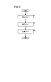
- FIG. 4 is a flowchart illustrating the flow of a motor sealing method according to the embodiment
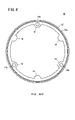
- FIG. 10 is a front view of a semi-metallic gasket according to Modification 1
- FIG. 10 is a front view of another semi-metallic gasket according to modification 1;
- FIG. 1 is a front view of a semi-metallic gasket 10 according to an embodiment.
- FIG. 1 shows each of a "first direction D1" and a "second direction D2" used in the following description.
- the semi-metallic gasket 10 is a sealing member for the motor 22.
- Motor 22 includes a first member (eg, core block 24 in FIG. 3) and a second member (eg, front housing 26 in FIG. 3).
- Each of the first member and the second member is a substantially cylindrical member having a ring-shaped cross section (end surface).
- the first member and the second member are connected to each other so as to connect the respective tubular inner peripheral spaces.
- a semi-metallic gasket 10 seals a gap between the first member and the second member.
- a semi-metallic gasket 10 illustrated in FIG. 1 A semi-metallic gasket 10 illustrated in FIG.
- the bead portion 12 has a ring shape corresponding to the end face shape (ring shape) of the first member and the end face shape (ring shape) of the second member.
- each of the core block 24 and the front housing 26 illustrated in FIG. 3 has a substantially polygonal ring shape (substantially octagonal ring shape).
- the bead portion 12 also has a substantially polygonal ring shape (substantially octagonal ring shape). Note that if each of the core block 24 and the front housing 26 has, for example, an annular shape, the bead portion 12 may also have an annular shape.
- the bead portion 12 receives pressure (surface pressure) from each of the first member and the second member. It is preferable that the surface pressure be applied to the entire bead portion 12 as uniformly as possible. Therefore, it is preferable that the entire bead portion 12 on the first direction D1 side contacts the end surface of the first member. Further, it is preferable that the entirety of the bead portion 12 on the second direction D2 side contacts the end surface of the second member. As a result, surface pressure is applied to the entire bead portion 12 on the first direction D1 side and the entire bead portion 12 on the second direction D2 side. In addition, it is preferable that the annular shape of the bead portion 12 is point-symmetrical with respect to the central point P of the annular shape. As a result, the surface pressure applied to the bead portion 12 can be easily made uniform.
- FIG. 2A is an end view taken along line IIA-IIA in FIG.
- the bead portion 12 has a metal base material 18 and a resin material 20. As shown in FIG.
- the resin material 20 coats the metal substrate 18 . Also, the resin material 20 has elasticity.
- the elastic resin material 20 is, for example, rubber.
- the surface pressure that the bead portion 12 receives from each of the first member and the second member is as large as possible.
- the bead portion 12 has a protruding portion (bead) 12a in order to maximize the surface pressure.
- the protrusion 12a protrudes in the first direction D1.
- the protruding portion 12a has a ring shape when viewed from the front (see FIG. 1).
- Such a projecting portion 12a can be easily formed by bending or curving the bead portion 12. As shown in FIG. When the bead portion 12 is in close contact with the second member, the protruding portion 12a is particularly strongly pressed against the second member. Therefore, the surface pressure that the bead portion 12 receives can be particularly increased at the projecting portion 12a.
- the width W12 of the bead portion 12 is thinned (reduced), the contact area between the bead portion 12 and the first member can be reduced. Similarly, if the width W12 of the bead portion 12 is thinned (reduced), the contact area of the bead portion 12 with the second member can be reduced. If the contact area of the bead portion 12 is reduced, the surface pressure that the bead portion 12 receives can be increased accordingly. Therefore, although it depends on the dimensions of the first member and the second member, it is preferable that the width W12 of the bead portion 12 is as thin (small) as possible.
- the thickness direction of the semi-metallic gasket 10 has a third direction D3 and a fourth direction D4 in FIG.
- Each of the third direction D3 and the fourth direction D4 is orthogonal to the first direction D1 (the second direction D2).
- the third direction D3 is a direction from the inside of the annular shape of the bead portion 12 to the outside of the annular shape.
- a fourth direction D4 is a direction opposite to the third direction D3.
- the robot sucks the semi-metallic gasket 10 with the sucking hand.
- the suction hand of the robot can easily pick up objects having a flat shape, but it is difficult to pick up objects having an uneven shape.
- the shape of the bead portion 12 having the projecting portion 12a is an uneven shape that is difficult to be sucked by the sucking hand of the robot.
- the bead portion 12 having a reduced thickness W12 is difficult to secure a contact area with the suction hand. As a result, it becomes difficult to suck the bead portion 12 with the suction hand. If the width W12 of the bead portion 12 is 1 cm or less, the suction with the suction hand becomes particularly difficult.
- FIG. 2B is an end view taken along line IIB-IIB in FIG.
- the semi-metallic gasket 10 of this embodiment includes the sucked portion 14 as described above. As illustrated in FIG. 2B, each of the plurality of sucked portions 14 is formed by widening the bead portion 12 in the thickness direction (fourth direction D4). Each of the plurality of attracted portions 14 has a surface 14a and a surface 14b. The surface 14a is a flat surface facing the first direction D1. The surface 14b is a flat surface on the back side of the surface 14a.
- the suction hand can suction each of the plurality of suctioned portions 14 even if the bead portion 12 has a small thickness W12. Moreover, each of the plurality of attracted portions 14 has a flat surface 14a (14b). As described above, the picking hand tends to pick up flat surfaces. Therefore, the semi-metallic gasket 10 of the present embodiment is easily sucked by a sucking hand.
- the plurality of sucked portions 14 are arranged such that at least two of the sucked portions 14 sandwich an imaginary straight line L passing through one point on the bead portion 12 and the center point P of the annular shape.
- the virtual straight line L is a virtual straight line passing through one point on the bead portion 12 and the center point P of the annular shape.
- both sides of the semi-metallic gasket 10 sandwiching the imaginary straight line L can be easily sucked by the sucking hands.
- the imaginary straight line L is not limited to the illustration in FIG. 1 as long as it passes through one point on the bead portion 12 and the center point P of the annular shape.
- the plurality of sucked portions 14 be arranged point-symmetrically about the central point P of the annular shape of the bead portion 12 (see FIG. 1). As a result, the surface pressure is easily applied uniformly over the entire semi-metallic gasket 10 .
- Each of the plurality of insertion portions 16 has a hole 16a (a through hole 16a penetrating through the semi-metallic gasket 10 in the second direction D2).
- a connecting member is inserted into each of the plurality of holes 16a.
- the connecting member is a member (for example, screw 34 in FIG. 4) that connects the first member and the second member.
- the plurality of insertion portions 16 be arranged point-symmetrically about the central point P of the annular shape of the bead portion 12 . That is, when the tightening force of screw 34 is increased, each of the first member and the second member strongly adheres to semi-metallic gasket 10 . As a result, the tightening force of the screw 34 acts particularly strongly around the hole 16a. As a result, the area around the hole 16a of the semi-metallic gasket 10 has a higher surface pressure than other areas.
- a large surface pressure can be uniformly applied to the entire semi-metallic gasket 10.
- FIG. 3 is a side view of the motor 22 according to the embodiment. 4 is an exploded perspective view of the motor 22 of FIG. 3.
- FIG. 3 is a side view of the motor 22 according to the embodiment. 4 is an exploded perspective view of the motor 22 of FIG. 3.
- the motor 22 provided with the semi-metallic gasket 10 includes a core block 24, a front housing 26, a rear housing 28, and a plurality of semi-metallic gaskets 10 (10A, 10B).
- the core block 24 is the stator of the motor 22.
- Core block 24 is cylindrical. Therefore, the core block 24 has an annular shape when viewed from the first direction D1.
- a shaft 30 is arranged inside the cylinder (ring) of the core block 24 .
- a shaft 30 is a shaft member for outputting the rotational force of the motor 22 .
- the front housing 26 is a case that covers the core block 24 from the first direction D1. Although illustration is omitted, the front housing 26 has an annular shape that matches the annular shape of the core block 24 when viewed from the second direction D2. Shaft 30 extends through front housing 26 . As shown in FIGS. 3 and 4, the front housing 26 may include a flange (plate-like joint) 26a. This facilitates coupling of the motor 22 to other mechanical devices.
- the core block 24 and the front housing 26 are connected to each other by a plurality of screws 34. That is, the core block 24 has a plurality of insertion holes 24a.
- the front housing 26 has a plurality of insertion holes 26b.
- the plurality of screws 34 are inserted through the plurality of insertion holes 24a and the plurality of insertion holes 26b. Thereby, the core block 24 and the front housing 26 are connected.
- the semi-metallic gasket 10A is arranged between the front housing 26 and the core block 24.
- the semi-metallic gasket 10A firmly seals the gap between the front housing 26 and the core block 24.
- the plurality of screws 34 are inserted through the plurality of holes 16a of the semi-metallic gasket 10A. Therefore, the semi-metallic gasket 10A does not interfere with the connection between the front housing 26 and the core block 24. As shown in FIG.
- the rear housing 28 is a case that covers the core block 24 from the second direction D2. Although illustration is omitted, the rear housing 28 has an annular shape that matches the core block 24 when viewed from the first direction D1.
- the rear housing 28 is connected to the second direction D2 side of the core block 24 by a plurality of screws 34, although illustration thereof is also omitted.
- the semi-metallic gasket 10B is arranged between the rear housing 28 and the core block 24.
- the semi-metallic gasket 10B is similar to the semi-metallic gasket 10A except that it is arranged between the rear housing 28 and the core block 24. As shown in FIG. Therefore, description of the semi-metallic gasket 10B is omitted.
- the motor 22 has a semi-metallic gasket 10 that is easily sucked by a sucking hand. Therefore, the motor 22 is easy to assemble for a robot equipped with a suction hand. Note that the location where the semi-metallic gasket 10 is attached is not particularly limited as long as it is a location that needs to be sealed in the motor 22 .
- This sealing method is a method for obtaining the motor 22 illustrated in FIGS.
- the sealing method is a method for obtaining the motor 22 illustrated in FIGS.
- the case where the semi-metallic gasket 10A seals between the front housing 26 and the core block 24 will be described below.
- FIG. 5 is a flow chart illustrating the flow of the sealing method for the motor 22 according to the embodiment.
- the sealing method includes a suction step S1, a placement step S2, and a close contact step S3. As illustrated in FIG. 5, the suction step S1, the placement step S2, and the close contact step S3 are executed in this order.
- the suction hand of the robot suctions the semi-metallic gasket 10A.
- the suction hand can easily suck the semi-metallic gasket 10 ⁇ /b>A by sucking the plurality of sucked portions 14 .
- the suction hand places the semi-metallic gasket 10A on the core block (first member) 24.
- a press presses the front housing (second member) 26 toward the core block 24 (second direction D2) from the side opposite to the core block 24.
- the front housing 26 and the semi-metallic gasket 10A are brought into close contact with each other.
- the semi-metallic gasket 10A and the core block 24 are closely attached.
- the press applies enough force to the front housing 26 to crush the protrusion 12a.
- the space between the front housing 26 and the core block 24 is firmly sealed by the semi-metallic gasket 10A.
- Any means other than the pressing machine may be used as long as it is possible to achieve close contact between the front housing 26 and the semi-metallic gasket 10A and between the semi-metallic gasket 10A and the core block 24.
- the semi-metallic gasket 10A may be placed on the front housing 26.
- the core block 24 is brought into close contact with the semi-metallic gasket 10A from the side opposite to the front housing 26. As shown in FIG.
- FIG. 6 is a front view of a semi-metallic gasket 10 according to Modification 1.
- FIG. 7 is a front view of another semi-metallic gasket 10 according to Modification 1.
- FIG. 6 is a front view of a semi-metallic gasket 10 according to Modification 1.
- FIG. 6 illustrates a semi-metallic gasket 10 having an annular bead portion 12 when viewed from the front and a projecting portion 12a having an annular shape when viewed from the front.
- FIG. 7 illustrates a semi-metallic gasket 10 having a substantially rectangular bead portion 12 when viewed from the front and a substantially rectangular projection 12a when viewed from the front.
- Each of the plurality of sucked portions 14 described in the embodiment extends from the bead portion 12 in the fourth direction D4. Without being limited to this, each of the plurality of sucked portions 14 may extend from the bead portion 12 in the third direction D3.
- the projecting portion 12a of the bead portion 12 may project in the second direction D2.
- the protrusion 12a is pressed particularly strongly against the first member (core block 24 in FIG. 3) when the bead portion 12 is in close contact with the first member. Even in this case, the surface pressure that the bead portion 12 receives can be particularly increased at the projecting portion 12a.
- the number of the sucked portions 14 provided in the semi-metallic gasket 10 is not limited to plural, and may be singular.
- a connector may be connected to the rear housing 28 .
- the semi-metallic gasket 10 may seal between the rear housing 28 and the connector.
- one of the rear housing 28 and the connector is the first member. Also, the remaining other is the second member.
- a bracket may be connected to the rear housing 28 .
- the semi-metallic gasket 10 may seal between the rear housing 28 and the bracket.
- one of the rear housing 28 and the bracket is the first member. Also, the remaining other is the second member.
- an encoder may be connected to the bracket.
- the semi-metallic gasket 10 may seal between the bracket and the encoder.
- one of the bracket and the encoder is the first member. Also, the remaining other is the second member.
- the number of semi-metallic gaskets 10 provided in the motor 22 may be changed as required.
- the number of semi-metallic gaskets 10 provided in the motor 22 may be singular.
- a motor (22) comprising a first member (24, 26, 28) and a second member (24, 26, 28) each having an annular cross-section, said first members (24, 26, 28) and A semi-metallic gasket (10) for sealing between the second member (24, 26, 28), which is attracted by a ring-shaped bead portion (12) made of semi-metal and a robot's suction hand.
- a sucked portion (14) is provided, and the sucked portion (14) protrudes from the bead portion (12) along the thickness direction of the bead portion (12).
- the annular shape of the bead portion (12) may be point-symmetrical with respect to the central point (P) of the annular shape of the bead portion (12). This makes it easier for the bead portion (12) to receive a uniform surface pressure.
- the first members (24, 26, 28) and the second members (24, 26, 28) are connected by a plurality of connecting members (34), and each of the plurality of connecting members (34) is inserted.
- a plurality of insertion portions (16) having holes (16a) may be provided, and the plurality of insertion portions (16) may be provided in the bead portion (12) point-symmetrically with respect to the center point (P). . This makes it easier for a large surface pressure to be uniformly applied to the bead portion (12).
- the semi-metallic gasket (10) includes at least two of the suctioned portions (14), and the two suctioned portions (14) are formed by one point on the ring-shaped bead portion (12) and the center point. (P) may be arranged so as to sandwich an imaginary straight line (L) passing through (P). This makes it easier to lift the semi-metallic gasket (10) with a suction hand in good balance (in a horizontal state).
- This provides a motor (22) that is easy to assemble for the robot.
- ⁇ Third Invention> Sealing between first members (24, 26, 28) and second members (24, 26, 28) provided in the motor (22) using the semi-metallic gasket (10) according to the first invention a sealing method comprising: a sucking step (S1) of sucking the sucked portion (14) of the semi-metallic gasket (10) by the sucking hand; and the semi-metallic gasket (10) sucked by the sucking hand. on the first members (24, 26, 28) of the motor (22); and a close contact step (S3) of bringing the semi-metallic gasket (10) into close contact with the side opposite to the first member (24, 26, 28).
- This provides a sealing method that is easy to automate.
Landscapes
- Engineering & Computer Science (AREA)
- Power Engineering (AREA)
- Gasket Seals (AREA)
- Iron Core Of Rotating Electric Machines (AREA)
- Motor Or Generator Frames (AREA)
Abstract
Description
図1は、実施形態に係るセミメタリックガスケット10の正面図である。図1には、以下の説明に用いる「第1方向D1」および「第2方向D2」の各々を示した。
以下、実施形態に係る変形例について、いくつかの具体例を開示する。なお、実施形態で既に説明した構成要素には、実施形態と同一の符号を付す。また、実施形態と重複する説明はできるだけ省略する。
図6は、変形例1に係るセミメタリックガスケット10の正面図である。図7は、変形例1に係る別のセミメタリックガスケット10の正面図である。
実施形態で説明した複数の被吸着部14の各々は、ビード部12から第4方向D4に向かって延在した。これに限定されず、複数の被吸着部14の各々は、ビード部12から第3方向D3に向かって延在してもよい。
ビード部12の突出部12aは、第2方向D2に突出してもよい。その場合、突出部12aは、ビード部12が第1部材(図3のコアブロック24)に密着するときに、第1部材に特に強く押し付けられる。この場合でも、ビード部12が受ける面圧を、突出部12aにおいて特に大きくできる。
セミメタリックガスケット10に備わる被吸着部14の数は複数に限定されず、単数でもよい。
実施形態において、セミメタリックガスケット10の組付け箇所が特に限定されない旨を説明した。これについて、本変形例では具体例を挙げておく。
モータ22に備わるセミメタリックガスケット10の数は、必要に応じて変更して構わない。例えばモータ22に備わるセミメタリックガスケット10の数は、単数でもよい。
上記実施形態および変形例から把握しうる発明について、以下に記載する。
各々の断面が環形状の第1部材(24、26、28)および第2部材(24、26、28)を備えるモータ(22)に設けられ、前記第1部材(24、26、28)と前記第2部材(24、26、28)との間をシールするセミメタリックガスケット(10)であって、セミメタルで構成された環形状のビード部(12)と、ロボットの吸着ハンドで吸着される被吸着部(14)と、を備え、前記被吸着部(14)は、前記ビード部(12)の肉幅方向に沿って前記ビード部(12)から突出している。
第1の発明に記載のセミメタリックガスケット(10)が設けられたモータ(22)であって、前記第1部材(24、26、28)および前記第2部材(24、26、28)を備え、前記第1部材(24、26、28)と前記第2部材(24、26、28)との間が前記セミメタリックガスケット(10)によりシールされている。
第1の発明に記載のセミメタリックガスケット(10)を用いて、前記モータ(22)に備わる第1部材(24、26、28)と第2部材(24、26、28)との間をシールするシール方法であって、前記吸着ハンドにより、前記セミメタリックガスケット(10)の前記被吸着部(14)を吸着する吸着ステップ(S1)と、前記吸着ハンドに吸着した前記セミメタリックガスケット(10)を前記モータ(22)の前記第1部材(24、26、28)上に載置する載置ステップ(S2)と、前記モータ(22)の前記第2部材(24、26、28)を前記第1部材(24、26、28)とは反対側から前記セミメタリックガスケット(10)に密着させる密着ステップ(S3)と、を含む。
14…被吸着部 16…挿入部
16a…孔 22…モータ
24…コアブロック(第1部材、第2部材)
26…前方ハウジング(第1部材、第2部材)
28…後方ハウジング(第1部材、第2部材)
34…ネジ(連結部材) L…仮想直線
P…中心点
Claims (6)
- 各々の断面が環形状の第1部材(24、26、28)および第2部材(24、26、28)を備えるモータ(22)に設けられ、前記第1部材と前記第2部材との間をシールするセミメタリックガスケット(10)であって、
セミメタルで構成された環形状のビード部(12)と、
ロボットの吸着ハンドで吸着される被吸着部(14)と、
を備え、
前記被吸着部は、前記ビード部の肉幅方向に沿って前記ビード部から突出している、セミメタリックガスケット。 - 請求項1に記載のセミメタリックガスケットであって、
前記ビード部の前記環形状は、前記ビード部の前記環形状の中心点(P)に対して点対称である、セミメタリックガスケット。 - 請求項2に記載のセミメタリックガスケットであって、
前記第1部材と前記第2部材とは複数の連結部材(34)によって連結され、
複数の前記連結部材の各々が挿入される孔(16a)を有する挿入部(16)を複数備え、
複数の前記挿入部は、前記中心点に対して点対称に前記ビード部に設けられている、セミメタリックガスケット。 - 請求項2または3に記載のセミメタリックガスケットであって、
前記被吸着部を少なくとも2つ備え、
2つの前記被吸着部は、前記環形状の前記ビード部上の一点と、前記中心点とを通る仮想直線(L)を挟むように配置されている、セミメタリックガスケット。 - 請求項1~4のいずれか1項に記載のセミメタリックガスケットが設けられたモータであって、
前記第1部材および前記第2部材を備え、
前記第1部材と前記第2部材との間が前記セミメタリックガスケットによりシールされている、モータ。 - 請求項1~4のいずれか1項に記載のセミメタリックガスケットを用いて、前記モータに備わる第1部材と第2部材との間をシールするモータのシール方法であって、
前記吸着ハンドにより、前記セミメタリックガスケットの前記被吸着部を吸着する吸着ステップ(S1)と、
前記吸着ハンドに吸着した前記セミメタリックガスケットを前記モータの前記第1部材上に載置する載置ステップ(S2)と、
前記モータの前記第2部材を前記第1部材とは反対側から前記セミメタリックガスケットに密着させる密着ステップ(S3)と、
を含む、モータのシール方法。
Priority Applications (11)
| Application Number | Priority Date | Filing Date | Title |
|---|---|---|---|
| US18/560,415 US20240258866A1 (en) | 2021-05-20 | 2021-05-20 | Semi-metallic gasket, motor, and method for sealing motor |
| PCT/JP2021/019206 WO2022244201A1 (ja) | 2021-05-20 | 2021-05-20 | セミメタリックガスケット、モータ、およびモータのシール方法 |
| DE112021007287.0T DE112021007287T5 (de) | 2021-05-20 | 2021-05-20 | Halbmetallische dichtung, motor und verfahren zum abdichten eines motors |
| JP2023522131A JP7849356B2 (ja) | 2021-05-20 | 2021-05-20 | セミメタリックガスケット、モータ、およびモータのシール方法 |
| CN202180098152.8A CN117280574A (zh) | 2021-05-20 | 2021-05-20 | 半金属垫片、马达以及马达的密封方法 |
| CN202280034856.3A CN117296231A (zh) | 2021-05-20 | 2022-02-16 | 电动机 |
| DE112022001488.1T DE112022001488T5 (de) | 2021-05-20 | 2022-02-16 | Elektromotor |
| JP2023522230A JP7723086B2 (ja) | 2021-05-20 | 2022-02-16 | 電動機 |
| PCT/JP2022/006073 WO2022244349A1 (ja) | 2021-05-20 | 2022-02-16 | 電動機 |
| US18/560,416 US12609577B2 (en) | 2021-05-20 | 2022-02-16 | Electric motor |
| JP2025241947A JP2026032290A (ja) | 2021-05-20 | 2025-12-09 | セミメタリックガスケット、モータ、およびモータのシール方法 |
Applications Claiming Priority (1)
| Application Number | Priority Date | Filing Date | Title |
|---|---|---|---|
| PCT/JP2021/019206 WO2022244201A1 (ja) | 2021-05-20 | 2021-05-20 | セミメタリックガスケット、モータ、およびモータのシール方法 |
Publications (1)
| Publication Number | Publication Date |
|---|---|
| WO2022244201A1 true WO2022244201A1 (ja) | 2022-11-24 |
Family
ID=84140192
Family Applications (2)
| Application Number | Title | Priority Date | Filing Date |
|---|---|---|---|
| PCT/JP2021/019206 Ceased WO2022244201A1 (ja) | 2021-05-20 | 2021-05-20 | セミメタリックガスケット、モータ、およびモータのシール方法 |
| PCT/JP2022/006073 Ceased WO2022244349A1 (ja) | 2021-05-20 | 2022-02-16 | 電動機 |
Family Applications After (1)
| Application Number | Title | Priority Date | Filing Date |
|---|---|---|---|
| PCT/JP2022/006073 Ceased WO2022244349A1 (ja) | 2021-05-20 | 2022-02-16 | 電動機 |
Country Status (5)
| Country | Link |
|---|---|
| US (2) | US20240258866A1 (ja) |
| JP (3) | JP7849356B2 (ja) |
| CN (2) | CN117280574A (ja) |
| DE (2) | DE112021007287T5 (ja) |
| WO (2) | WO2022244201A1 (ja) |
Families Citing this family (1)
| Publication number | Priority date | Publication date | Assignee | Title |
|---|---|---|---|---|
| JPWO2024127464A1 (ja) * | 2022-12-12 | 2024-06-20 |
Citations (8)
| Publication number | Priority date | Publication date | Assignee | Title |
|---|---|---|---|---|
| JPH10118857A (ja) * | 1996-10-25 | 1998-05-12 | Mitsubishi Automob Eng Co Ltd | エンジン部品組付装置および組付方法とガスケット供給方法 |
| JP2002005291A (ja) * | 2000-06-26 | 2002-01-09 | Gomuno Inaki Kk | 冷媒シール用ガスケットの装着構造 |
| JP2008167609A (ja) * | 2006-12-28 | 2008-07-17 | Mitsubishi Motors Corp | 電動機 |
| JP2013076352A (ja) * | 2011-09-30 | 2013-04-25 | Mitsubishi Motors Corp | 気体流路結合部の遮熱構造 |
| JP2014231868A (ja) * | 2013-05-29 | 2014-12-11 | Ntn株式会社 | 電動リニアアクチュエータ |
| JP2016032332A (ja) * | 2014-07-28 | 2016-03-07 | 株式会社豊田自動織機 | 回転電機 |
| JP2016142387A (ja) * | 2015-02-04 | 2016-08-08 | 本田技研工業株式会社 | メタルガスケット |
| JP2018055763A (ja) * | 2016-09-26 | 2018-04-05 | トヨタ自動車株式会社 | 燃料電池の製造方法 |
Family Cites Families (10)
| Publication number | Priority date | Publication date | Assignee | Title |
|---|---|---|---|---|
| JPH0222042U (ja) * | 1988-07-28 | 1990-02-14 | ||
| JPH09149582A (ja) | 1995-11-24 | 1997-06-06 | Fanuc Ltd | 回転電機の防水型外郭構造 |
| US6755009B1 (en) * | 2000-03-24 | 2004-06-29 | Eastman Kodak Company | Method for making and handling an intraoral x-ray film packet |
| JP3991610B2 (ja) | 2001-04-03 | 2007-10-17 | いすゞ自動車株式会社 | ストレーナ |
| DE50202326D1 (de) * | 2002-08-23 | 2005-03-31 | Festo Ag & Co Kg | Dichtungsring |
| DE102007019330A1 (de) * | 2007-04-24 | 2008-10-30 | Reinz-Dichtungs-Gmbh | Dreidimensionale Flachdichtung |
| JP2010074990A (ja) | 2008-09-19 | 2010-04-02 | Yamada Seisakusho Co Ltd | ポンプ用dcモータの放熱構造 |
| JP2013207815A (ja) | 2012-03-27 | 2013-10-07 | Honda Motor Co Ltd | 電動機ケース構造 |
| CN206807204U (zh) * | 2017-06-27 | 2017-12-26 | 利欧集团浙江泵业有限公司 | 一种电机接线盒组件 |
| JP7294976B2 (ja) * | 2019-09-30 | 2023-06-20 | ファナック株式会社 | モータ |
-
2021
- 2021-05-20 CN CN202180098152.8A patent/CN117280574A/zh active Pending
- 2021-05-20 US US18/560,415 patent/US20240258866A1/en active Pending
- 2021-05-20 DE DE112021007287.0T patent/DE112021007287T5/de active Pending
- 2021-05-20 WO PCT/JP2021/019206 patent/WO2022244201A1/ja not_active Ceased
- 2021-05-20 JP JP2023522131A patent/JP7849356B2/ja active Active
-
2022
- 2022-02-16 CN CN202280034856.3A patent/CN117296231A/zh active Pending
- 2022-02-16 US US18/560,416 patent/US12609577B2/en active Active
- 2022-02-16 WO PCT/JP2022/006073 patent/WO2022244349A1/ja not_active Ceased
- 2022-02-16 JP JP2023522230A patent/JP7723086B2/ja active Active
- 2022-02-16 DE DE112022001488.1T patent/DE112022001488T5/de active Pending
-
2025
- 2025-12-09 JP JP2025241947A patent/JP2026032290A/ja active Pending
Patent Citations (8)
| Publication number | Priority date | Publication date | Assignee | Title |
|---|---|---|---|---|
| JPH10118857A (ja) * | 1996-10-25 | 1998-05-12 | Mitsubishi Automob Eng Co Ltd | エンジン部品組付装置および組付方法とガスケット供給方法 |
| JP2002005291A (ja) * | 2000-06-26 | 2002-01-09 | Gomuno Inaki Kk | 冷媒シール用ガスケットの装着構造 |
| JP2008167609A (ja) * | 2006-12-28 | 2008-07-17 | Mitsubishi Motors Corp | 電動機 |
| JP2013076352A (ja) * | 2011-09-30 | 2013-04-25 | Mitsubishi Motors Corp | 気体流路結合部の遮熱構造 |
| JP2014231868A (ja) * | 2013-05-29 | 2014-12-11 | Ntn株式会社 | 電動リニアアクチュエータ |
| JP2016032332A (ja) * | 2014-07-28 | 2016-03-07 | 株式会社豊田自動織機 | 回転電機 |
| JP2016142387A (ja) * | 2015-02-04 | 2016-08-08 | 本田技研工業株式会社 | メタルガスケット |
| JP2018055763A (ja) * | 2016-09-26 | 2018-04-05 | トヨタ自動車株式会社 | 燃料電池の製造方法 |
Also Published As
| Publication number | Publication date |
|---|---|
| JPWO2022244201A1 (ja) | 2022-11-24 |
| DE112022001488T5 (de) | 2024-02-01 |
| CN117280574A (zh) | 2023-12-22 |
| DE112021007287T5 (de) | 2024-01-25 |
| JP2026032290A (ja) | 2026-02-25 |
| JP7723086B2 (ja) | 2025-08-13 |
| WO2022244349A1 (ja) | 2022-11-24 |
| JPWO2022244349A1 (ja) | 2022-11-24 |
| JP7849356B2 (ja) | 2026-04-21 |
| US12609577B2 (en) | 2026-04-21 |
| US20240258866A1 (en) | 2024-08-01 |
| US20240250574A1 (en) | 2024-07-25 |
| CN117296231A (zh) | 2023-12-26 |
Similar Documents
| Publication | Publication Date | Title |
|---|---|---|
| JP2026032290A (ja) | セミメタリックガスケット、モータ、およびモータのシール方法 | |
| CN1218550C (zh) | 压电型电声换能器及其制造方法 | |
| JP5385826B2 (ja) | 気密容器、真空ポンプ | |
| JP5528778B2 (ja) | シール構造 | |
| JPH11267986A (ja) | シート吸着板 | |
| JP5435636B2 (ja) | 手摺り | |
| CN212811453U (zh) | 电机装置 | |
| JP2004032958A (ja) | 電動機の回転子構造 | |
| JP3890859B2 (ja) | 圧電ダイヤフラムポンプの製造方法 | |
| US10903727B2 (en) | Stator core of rotary electric machine | |
| JP2006004720A (ja) | 防水フラットケーブル | |
| JP2020009918A (ja) | 搬送用ハンド | |
| JP2524913Y2 (ja) | グロメットのシール構造 | |
| WO2022134216A1 (zh) | 一种振动电机 | |
| JPH0753912Y2 (ja) | 真空吸着装置 | |
| JP2002260692A (ja) | 燃料電池用構成部品 | |
| JP4784462B2 (ja) | 防水構造 | |
| US12414255B2 (en) | Lead holding portion structure and motor | |
| CN212863758U (zh) | 一种电梯板材安装辅助工装 | |
| JP2002184849A (ja) | 薄板材料の把持装置 | |
| CN217152958U (zh) | 密封圈及防尘防水音箱 | |
| CN115009849A (zh) | 吸盘组件和手机排线按压装置 | |
| JPH10107454A (ja) | 筐体接合部のシール構造 | |
| JP2002142402A (ja) | 電動機 | |
| JP2011171761A (ja) | 防水構造及びパッキング |
Legal Events
| Date | Code | Title | Description |
|---|---|---|---|
| 121 | Ep: the epo has been informed by wipo that ep was designated in this application |
Ref document number: 21940815 Country of ref document: EP Kind code of ref document: A1 |
|
| WWE | Wipo information: entry into national phase |
Ref document number: 2023522131 Country of ref document: JP |
|
| WWE | Wipo information: entry into national phase |
Ref document number: 202180098152.8 Country of ref document: CN Ref document number: 18560415 Country of ref document: US Ref document number: 112021007287 Country of ref document: DE |
|
| 122 | Ep: pct application non-entry in european phase |
Ref document number: 21940815 Country of ref document: EP Kind code of ref document: A1 |