WO2022239827A1 - Instrument hémostatique - Google Patents
Instrument hémostatique Download PDFInfo
- Publication number
- WO2022239827A1 WO2022239827A1 PCT/JP2022/020040 JP2022020040W WO2022239827A1 WO 2022239827 A1 WO2022239827 A1 WO 2022239827A1 JP 2022020040 W JP2022020040 W JP 2022020040W WO 2022239827 A1 WO2022239827 A1 WO 2022239827A1
- Authority
- WO
- WIPO (PCT)
- Prior art keywords
- tube
- hemostatic device
- support member
- expansion
- curved
- Prior art date
Links
- 230000002439 hemostatic effect Effects 0.000 title claims abstract description 148
- 239000000463 material Substances 0.000 claims description 22
- 238000002347 injection Methods 0.000 claims description 11
- 239000007924 injection Substances 0.000 claims description 11
- 230000000740 bleeding effect Effects 0.000 claims description 10
- 239000012530 fluid Substances 0.000 claims description 10
- 238000003780 insertion Methods 0.000 claims description 2
- 230000037431 insertion Effects 0.000 claims description 2
- 239000003550 marker Substances 0.000 description 15
- 238000006073 displacement reaction Methods 0.000 description 13
- 238000000034 method Methods 0.000 description 10
- 210000003811 finger Anatomy 0.000 description 7
- -1 polyethylene Polymers 0.000 description 7
- 238000005452 bending Methods 0.000 description 6
- 210000004204 blood vessel Anatomy 0.000 description 6
- 210000000245 forearm Anatomy 0.000 description 5
- 230000023597 hemostasis Effects 0.000 description 5
- 229920005989 resin Polymers 0.000 description 5
- 239000011347 resin Substances 0.000 description 5
- 210000001367 artery Anatomy 0.000 description 4
- 229920001971 elastomer Polymers 0.000 description 4
- 239000000806 elastomer Substances 0.000 description 4
- 210000003414 extremity Anatomy 0.000 description 4
- 238000012986 modification Methods 0.000 description 4
- 230000004048 modification Effects 0.000 description 4
- 229920000139 polyethylene terephthalate Polymers 0.000 description 4
- 239000005020 polyethylene terephthalate Substances 0.000 description 4
- 241000385250 Epioblasma triquetra Species 0.000 description 3
- 238000010586 diagram Methods 0.000 description 3
- 239000012528 membrane Substances 0.000 description 3
- 238000000465 moulding Methods 0.000 description 3
- 239000004800 polyvinyl chloride Substances 0.000 description 3
- 229920000915 polyvinyl chloride Polymers 0.000 description 3
- 210000003813 thumb Anatomy 0.000 description 3
- 239000004677 Nylon Substances 0.000 description 2
- 239000005062 Polybutadiene Substances 0.000 description 2
- 239000004698 Polyethylene Substances 0.000 description 2
- 239000004743 Polypropylene Substances 0.000 description 2
- 229920000122 acrylonitrile butadiene styrene Polymers 0.000 description 2
- 150000001408 amides Chemical class 0.000 description 2
- 230000005540 biological transmission Effects 0.000 description 2
- 239000005038 ethylene vinyl acetate Substances 0.000 description 2
- 210000005224 forefinger Anatomy 0.000 description 2
- 238000009434 installation Methods 0.000 description 2
- 229920001778 nylon Polymers 0.000 description 2
- 229920001200 poly(ethylene-vinyl acetate) Polymers 0.000 description 2
- 229920003229 poly(methyl methacrylate) Polymers 0.000 description 2
- 229920002857 polybutadiene Polymers 0.000 description 2
- 229920001707 polybutylene terephthalate Polymers 0.000 description 2
- 229920000728 polyester Polymers 0.000 description 2
- 229920000573 polyethylene Polymers 0.000 description 2
- 239000004926 polymethyl methacrylate Substances 0.000 description 2
- 229920000098 polyolefin Polymers 0.000 description 2
- 229920001155 polypropylene Polymers 0.000 description 2
- 210000002321 radial artery Anatomy 0.000 description 2
- 229920000178 Acrylic resin Polymers 0.000 description 1
- 239000004925 Acrylic resin Substances 0.000 description 1
- 239000002033 PVDF binder Substances 0.000 description 1
- 229930182556 Polyacetal Natural products 0.000 description 1
- 239000004952 Polyamide Substances 0.000 description 1
- 239000004793 Polystyrene Substances 0.000 description 1
- 229920001328 Polyvinylidene chloride Polymers 0.000 description 1
- BZHJMEDXRYGGRV-UHFFFAOYSA-N Vinyl chloride Chemical compound ClC=C BZHJMEDXRYGGRV-UHFFFAOYSA-N 0.000 description 1
- XECAHXYUAAWDEL-UHFFFAOYSA-N acrylonitrile butadiene styrene Chemical compound C=CC=C.C=CC#N.C=CC1=CC=CC=C1 XECAHXYUAAWDEL-UHFFFAOYSA-N 0.000 description 1
- 239000004676 acrylonitrile butadiene styrene Substances 0.000 description 1
- 239000000956 alloy Substances 0.000 description 1
- 229910045601 alloy Inorganic materials 0.000 description 1
- 210000001142 back Anatomy 0.000 description 1
- 238000004891 communication Methods 0.000 description 1
- 239000000470 constituent Substances 0.000 description 1
- 230000004927 fusion Effects 0.000 description 1
- 238000001802 infusion Methods 0.000 description 1
- 229920000554 ionomer Polymers 0.000 description 1
- 230000003902 lesion Effects 0.000 description 1
- 238000004519 manufacturing process Methods 0.000 description 1
- 239000000203 mixture Substances 0.000 description 1
- 230000000149 penetrating effect Effects 0.000 description 1
- 229920000058 polyacrylate Polymers 0.000 description 1
- 229920002239 polyacrylonitrile Polymers 0.000 description 1
- 229920002647 polyamide Polymers 0.000 description 1
- 229920000515 polycarbonate Polymers 0.000 description 1
- 239000004417 polycarbonate Substances 0.000 description 1
- 229920001225 polyester resin Polymers 0.000 description 1
- 239000004645 polyester resin Substances 0.000 description 1
- 229920000642 polymer Polymers 0.000 description 1
- 229920000306 polymethylpentene Polymers 0.000 description 1
- 229920006324 polyoxymethylene Polymers 0.000 description 1
- 229920001296 polysiloxane Polymers 0.000 description 1
- 229920002223 polystyrene Polymers 0.000 description 1
- 229920002635 polyurethane Polymers 0.000 description 1
- 239000004814 polyurethane Substances 0.000 description 1
- 229920003225 polyurethane elastomer Polymers 0.000 description 1
- 229920005749 polyurethane resin Polymers 0.000 description 1
- 239000005033 polyvinylidene chloride Substances 0.000 description 1
- 229920002981 polyvinylidene fluoride Polymers 0.000 description 1
- 210000002435 tendon Anatomy 0.000 description 1
- 229920002725 thermoplastic elastomer Polymers 0.000 description 1
Images


Classifications
-
- A—HUMAN NECESSITIES
- A61—MEDICAL OR VETERINARY SCIENCE; HYGIENE
- A61B—DIAGNOSIS; SURGERY; IDENTIFICATION
- A61B17/00—Surgical instruments, devices or methods, e.g. tourniquets
- A61B17/12—Surgical instruments, devices or methods, e.g. tourniquets for ligaturing or otherwise compressing tubular parts of the body, e.g. blood vessels, umbilical cord
- A61B17/132—Tourniquets
- A61B17/135—Tourniquets inflatable
-
- A—HUMAN NECESSITIES
- A61—MEDICAL OR VETERINARY SCIENCE; HYGIENE
- A61B—DIAGNOSIS; SURGERY; IDENTIFICATION
- A61B17/00—Surgical instruments, devices or methods, e.g. tourniquets
- A61B17/12—Surgical instruments, devices or methods, e.g. tourniquets for ligaturing or otherwise compressing tubular parts of the body, e.g. blood vessels, umbilical cord
- A61B17/132—Tourniquets
- A61B17/1322—Tourniquets comprising a flexible encircling member
-
- A—HUMAN NECESSITIES
- A61—MEDICAL OR VETERINARY SCIENCE; HYGIENE
- A61B—DIAGNOSIS; SURGERY; IDENTIFICATION
- A61B17/00—Surgical instruments, devices or methods, e.g. tourniquets
- A61B2017/00477—Coupling
-
- A—HUMAN NECESSITIES
- A61—MEDICAL OR VETERINARY SCIENCE; HYGIENE
- A61B—DIAGNOSIS; SURGERY; IDENTIFICATION
- A61B17/00—Surgical instruments, devices or methods, e.g. tourniquets
- A61B2017/00831—Material properties
- A61B2017/00902—Material properties transparent or translucent
- A61B2017/00907—Material properties transparent or translucent for light
-
- A—HUMAN NECESSITIES
- A61—MEDICAL OR VETERINARY SCIENCE; HYGIENE
- A61B—DIAGNOSIS; SURGERY; IDENTIFICATION
- A61B17/00—Surgical instruments, devices or methods, e.g. tourniquets
- A61B17/12—Surgical instruments, devices or methods, e.g. tourniquets for ligaturing or otherwise compressing tubular parts of the body, e.g. blood vessels, umbilical cord
- A61B2017/12004—Surgical instruments, devices or methods, e.g. tourniquets for ligaturing or otherwise compressing tubular parts of the body, e.g. blood vessels, umbilical cord for haemostasis, for prevention of bleeding
-
- A—HUMAN NECESSITIES
- A61—MEDICAL OR VETERINARY SCIENCE; HYGIENE
- A61B—DIAGNOSIS; SURGERY; IDENTIFICATION
- A61B90/00—Instruments, implements or accessories specially adapted for surgery or diagnosis and not covered by any of the groups A61B1/00 - A61B50/00, e.g. for luxation treatment or for protecting wound edges
- A61B90/08—Accessories or related features not otherwise provided for
- A61B2090/0807—Indication means
-
- A—HUMAN NECESSITIES
- A61—MEDICAL OR VETERINARY SCIENCE; HYGIENE
- A61B—DIAGNOSIS; SURGERY; IDENTIFICATION
- A61B90/00—Instruments, implements or accessories specially adapted for surgery or diagnosis and not covered by any of the groups A61B1/00 - A61B50/00, e.g. for luxation treatment or for protecting wound edges
- A61B90/39—Markers, e.g. radio-opaque or breast lesions markers
- A61B2090/3937—Visible markers
Definitions
- the present invention relates to a hemostatic device.
- the hemostatic device of Patent Document 1 includes an expansion member that applies pressure to a puncture site formed in a patient's hand, a fixing member that fixes the pressure member to the patient's hand, and a fluid that expands the expansion member.
- an injection member comprising a port (connector portion) configured to allow injection of , a tube portion connecting the connector portion and the lumen of the expansion member; and a tube located in the fixing member and configured to allow the tube portion to be fixed. and a fixed portion.
- an operator such as a doctor (hereinafter referred to as "operator") uses the hemostatic device of Patent Document 1 to stop bleeding at the puncture site formed in the patient's hand, the expansion member is formed in the patient's hand.
- the hemostatic device By securing the hemostatic device using each strap while positioned at and around the puncture site, it is possible to prevent the expansion member from being displaced from the puncture site formed in the patient's hand. Further, by fixing the tube part to the tube fixing part, the operator can reduce the movement of the tube part following the movement of the patient's hand.
- the hemostatic device described in Patent Document 1 may have the following problems.
- the tube fixing portion is provided with a groove portion for fixing the tube portion. Therefore, when the operator attaches and detaches the tube portion from the tube fixing portion, the operator needs to apply an external force to the tube portion to deform (for example, elastically deform) the tube fixing portion in a direction that widens the groove. At this time, the force required for the operator to deform the tube fixing part in the direction to widen the groove is determined by the mechanical configuration of the tube fixing part. It may not have been designed with this in mind.
- an external force (force applied by the operator) is transmitted to the expansion member via the fixing member provided with the tube fixing part.
- an external force may be unintentionally applied to the puncture site.
- external forces imparted to the fixation member may inadvertently impart external forces to the expandable member, thereby displacing the expandable member from the puncture site formed in the patient's hand.
- the present invention has been made in view of the above problems, and when an operator attaches and detaches the tube portion from the tube fixing portion while the hemostatic device is attached to the patient's hand, the external force applied to the tube portion by the operator is applied to the tube fixing portion and the tube fixing portion.
- the expansion member via the fixing member By transmitting to the expansion member via the fixing member, external force is prevented from being unintentionally applied to the puncture site, and/or the external force applied to the tube portion by the operator is transmitted to the fixing member via the tube fixing portion. Accordingly, it is an object of the present invention to prevent displacement of the hemostatic device that may occur due to unintentional application of an external force to the expansion member.
- a hemostatic device comprises an expansion member configured to be able to press a site of a patient's limb to stop bleeding, a fixing member configured to be capable of fixing the expansion member to the patient's limb, and the expansion member.
- an injection member comprising: a connector portion configured to allow injection of a fluid for expansion; and a tube portion connecting the connector portion and a lumen of the expansion member; a tube fixing portion configured to be able to hold the tube, the tube fixing portion comprising a first member and a second member positioned closer to the expansion member than the first member and facing the first member; , a slit portion formed between the first member and the second member and configured so that the tube portion can be inserted; surrounded by the first member, the second member, and the slit portion; a tube holding portion configured to hold a tube portion, wherein the first member includes a first body portion, a first curved portion curved toward the second member, and the first curved portion.
- the second member includes a second body portion, a second curved portion curved toward the first member, and a distal end of the second curved portion.
- a second tip end face facing across the first tip face and the slit part, and a part of the first member is positioned relative to the virtual plane formed by the slit part rather than the second member and is separated from the expansion member in a vertical direction
- the first tip face includes a first region that does not face the second tip face across the slit portion, and a first region that does not face the second tip face across the slit portion. and a second region corresponding to , wherein the first curved portion has a first curved surface that curves toward the second member side, and the first curved surface is formed by the second tip surface and the They face each other across the tube holder.
- the distal end surface (first distal surface) of the first member and the second The tip faces (second tip faces) of the members are configured to have a smaller area facing each other with the slit portion interposed therebetween. Therefore, when the tube portion is pushed into the tube fixing portion (inserted into the tube fixing portion) by the operator, the first member is deformed in the direction in which the slit portion expands, and then the second member is deformed. As a result, the above-described hemostatic device can reduce the force required when the operator inserts the tube portion into the tube fixing portion while the hemostatic device is attached to the patient's hand.
- the first member of the hemostatic device has a first curved surface at a position facing the second distal end surface of the second member with the tube holding portion interposed therebetween. Therefore, when the tube part is pulled away from the tube fixing part (removed from the tube fixing part) by the operator, the tube part moves from the tube holding part toward the slit part using the first curved surface as a guiding surface.
- the above-described hemostatic device can reduce the force required when the operator removes the tube section from the tube fixing section. In this way, the above-described hemostatic device can reduce the force required when the operator attaches and detaches the tube portion from the tube fixing portion while the device is attached to the patient's hand. and/or to prevent displacement of the hemostatic device that may occur due to unintentional application of an external force to the expansion member.
- FIG. 4 is a diagram showing the hemostatic device according to the embodiment, and is a plan view of each band as viewed from the outer surface side.
- FIG. 4 is a view showing the hemostatic device according to the embodiment, and is a plan view seen from the inner surface side of each band.
- FIG. 4 is a plan view showing an enlarged part of the hemostatic device seen from the outer surface side of each band.
- FIG. 4 is a plan view showing an enlarged part of the hemostatic device seen from the inner surface side of each band.
- FIG. 4 is a plan view showing an enlarged part of the hemostatic device seen from the outer surface side of each band.
- FIG. 6A is a cross-sectional view of the hemostatic device taken along arrows 6A-6A shown in FIG.
- FIG. 7A is a cross-sectional view of the hemostatic device taken along arrows 7A-7A shown in FIG. 5, showing the expansion member as it expands; It is a perspective view which shows a support member. It is a perspective view which shows a support member.
- FIG. 8 is a cross-sectional view showing a tube fixing portion, and is a partially enlarged view of FIG. 7;
- FIG. 3 shows a patient's hand (right hand) to be used with the hemostatic device. It is a figure which shows simply the usage example of a hemostatic instrument. It is a figure which shows simply the usage example of a hemostatic instrument. It is a figure which shows simply the usage example of a hemostatic instrument. It is a figure which shows simply the usage example of a hemostatic instrument.
- FIG. 15A is a partial cross-sectional view taken along arrows 15A-15A shown in FIG. 14;
- FIG. 16A is a partial cross-sectional view taken along arrows 16A-16A shown in FIG. 14;
- FIG. 11 is a plan view showing an enlarged part of the hemostatic device according to Modification 1;
- FIGS. 1 to 10 are diagrams for explaining the hemostatic device 100 according to this embodiment, and FIGS. 11 to 16 are diagrams for explaining usage examples of the hemostatic device 100.
- FIG. 1 to 10 are diagrams for explaining the hemostatic device 100 according to this embodiment
- FIGS. 11 to 16 are diagrams for explaining usage examples of the hemostatic device 100.
- the hemostatic device 100 is, for example, as shown in FIGS. 11 and 14 to 16, a puncture site (for example, a puncture site described later) formed in the hand H located distally (on the finger side) of the patient's forearm A.
- a puncture site for example, a puncture site described later
- the specific position of the puncture site to be stopped by the hemostatic device 100 is not particularly limited, the following first puncture site p1 is exemplified in this embodiment.
- the first puncture site p1 is, as shown in FIG. 11, the artery B located in the snuff box of the palmar artery running on the back Hb side of the right hand H1 (hand H) located distal to the forearm A of the patient. (hereinafter also referred to as “blood vessel B”).
- the snuff box is a cavity in the hand located near the radius when the patient spreads the thumb of the hand H.
- the second puncture site p2 is a puncture site formed in the distal radial artery located distal to the snuff box of the palmar artery running on the back Hb side of the patient's right hand H1.
- the second puncture site p2 is located on the distal side of the right hand H1 relative to the first puncture site p1 with reference to the extensor pollicis longus tendon t located on the back Hb of the patient's right hand H1.
- the hemostatic device 100 will be described in detail below.
- the hemostatic device 100 is configured to compress a first puncture site p1 formed in the patient's right hand H1;
- a fixing member 120 configured to be able to fix the expansion member 110 to the right hand H1 of the patient, a connector portion 181 configured to be capable of injecting fluid for expanding the expansion member 110, and an inner portion of the connector portion 181 and the expansion member 110.
- a tube portion 183 that connects the cavity 113 , an injection member 180 , and a tube fixing portion 300 that is located in the fixing member 120 and configured to fix the tube portion 183 .
- Expansion member 110 may consist of a single balloon with lumen 113 bounded by a membrane, as shown in FIGS.
- the expansion member 110 is formed, for example, by joining the edges of two sheet-like membrane materials formed in a substantially rectangular shape with a lumen 113 formed between the two sheet-like membrane materials. be able to.
- the expansion member 110 may be composed of, for example, a sheet of membrane-like member formed in a bag-like shape so as to have a lumen.
- the expansion member 110 expands when fluid such as air is supplied to the lumen 113 and contracts when the fluid supplied to the lumen 113 is discharged.
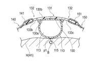
- 6 and 7 show cross-sectional views when the expansion member 110 is expanded by supplying fluid to the expansion member 110.
- the film material forming the expansion member 110 can be made of, for example, a resin material having a predetermined thickness.
- a tube portion 183 (see FIGS. 1 and 2), which will be described later, is connected to the lumen 113 of the expansion member 110 .
- the material of the film material constituting the expansion member 110 is not particularly limited, but examples include polyvinyl chloride, polyethylene, polypropylene, polybutadiene, polyolefin such as ethylene-vinyl acetate copolymer (EVA), polyethylene terephthalate (PET), Polyester such as polybutylene terephthalate (PBT), polyvinylidene chloride, silicone, polyurethane, polyamide elastomer, polyurethane elastomer, various thermoplastic elastomers such as polyester elastomer, nylon, nylon elastomer, or any combination thereof (blend resin, polymer alloys, laminates, etc.) can be used.
- polyvinyl chloride polyethylene, polypropylene, polybutadiene
- polyolefin such as ethylene-vinyl acetate copolymer (EVA), polyethylene terephthalate (PET), Polyester such as polybutylene terephthalate (PBT), polyvinylid
- the expansion member 110 is arranged on the inner surface 130a side of the support member 130 included in the fixing member 120, as shown in FIGS.
- the inner surface 130a of the support member 130 is a surface that is arranged on the body surface side of the patient's hand H when the hemostatic device 100 is attached to the patient's hand H.
- the outer surface 130b of the support member 130 is a surface located on the opposite side of the inner surface 130a.
- the expansion member 110 can be directly connected to the inner surface 130 a of the support member 130 . Fusion or adhesion, for example, can be used to connect the expansion member 110 and the support member 130 .
- the expansion member 110 may be connected to the inner surface 130a of the support member 130 via another member.
- the expansion member 110 may be composed of a sheet of membrane-like member configured to form a lumen with the inner surface 130 a of the support member 130 .
- expansion member 110 may directly connect a sheet of membrane-like member to inner surface 130a of support member 130 and include a lumen between inner surface 130a of support member 130 and the sheet of membrane-like member. can be configured as
- the expansion member 110 has a circular shape in a plan view shown in FIGS. 1 to 5.
- the shape of the expansion member 110 in plan view is not limited to a circle.
- the expansion member 110 is provided with a marker 115 for aligning the expansion member 110 with the first puncture site p1. .
- the marker 115 is located on the side opposite to the side on which the support member 130 of the expansion member 110 is arranged (the side arranged on the body surface side of the patient's hand H when the hemostatic device 100 is attached to the patient's hand H). ) on the outer surface of the
- the marker 115 is arranged on the expansion member 110, there is no particular limitation on the specific arrangement location.
- the marker 115 is placed on the side of the expansion member 110 opposite to the side on which the support member 130 is arranged (on the body surface side of the patient's hand H when the hemostatic device 100 is attached to the patient's hand H). It may be placed on the inner surface of the
- the marker 115 is arranged substantially at the center of the extension member 110 in the plane direction.
- the marker 115 is arranged so as to overlap the substantially center position of the support member 130 in the surface direction.
- the plane direction of the expansion member 110 and the plane direction of the support member 130 mean the direction in which the support member 130 (expansion member 110) extends in plan view shown in FIG.
- the marker 115 can be formed, for example, by a rectangular marker in which the entire marker 115 is colored.
- the shape, size, color, forming method, position, etc. of the marker 115 are not particularly limited.
- markers 115 may be provided on support member 130 .
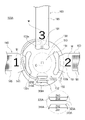
- the securing member 120 includes a support member 130 and a plurality of straps 140, 150, 160 configured to be connectable to the support member 130 and configured to wrap around the patient's hand H, as shown in FIG. have.
- the support member 130 includes a first region 131 in which the expansion member 110 is arranged, and a first band 140 and a second band 150 located outside the first region 131. , and a second region 132 to which the third strap 160 can be connected.
- the support member 130 has a circular shape in plan view shown in FIG.
- the first area 131 is an area where the expansion member 110 overlaps in plan view shown in FIG.
- the second region 132 is a region positioned outside the first region 131 in plan view shown in FIG.
- first region 131 can be arbitrarily defined based on the outer shape and size of the expansion member 110 arranged on the support member 130 .
- second area 132 can be defined based on the relative positional relationship with the first area 131 . Therefore, the first region 131 and the second region 132 can be appropriately changed according to the external shape and size of the expansion member 110 arranged on the support member 130 .
- a center point R which is the center when the first band 140 and the second band 150 slide along the second holes 133b and 133c is provided. is located.
- the center point R is positioned substantially at the center of the support member 130 in the plane direction. Therefore, as shown in FIGS. 6 and 7, the center point R is located at a position overlapping with the marker 115 when projected onto the expansion member 110 .
- the second region 132 is formed with a first hole 133a and a pair of second holes 133b and 133c facing each other with the expansion member 110 interposed therebetween. .
- the first hole 133a is arranged on the distal side (fingertip side) of the patient's hand H relative to the expansion member 110 when the hemostatic device 100 is attached to the patient's hand H.
- the second hole portion 133b and the second hole portion 133c are formed by a straight line connecting the first hole portion 133a and the expansion member 110 (a straight line connecting the first hole portion 133a and the tube fixing portion 300). 5 as a phantom line C).
- the holes 133a, 133b, and 133c are arranged on a virtual circle along the outer shape of the support member 130, as shown in FIGS.
- a first band 140 is connected to the second hole 133b.
- a second band 150 is connected to the second hole 133c.
- a third band 160 is connected to the first hole 133a.
- the width of one end 141 of the first band 140 is smaller than the hole length of the second hole 133b. Therefore, as shown in FIG. 8, the first band 140 is arranged so that the one end 141 of the first band 140 is connected to the second hole 133b, and the center point R of the support member 130 is the center.
- the second region 132 is slidable around the extension member 110 .
- the width of one end 151 of the second band 150 is smaller than the hole length of the second hole 133c. Therefore, as shown in FIG. 8, the second band 150 is in a state where one end 151 of the second band 150 is connected to the second hole 133c, and the second region 132 is centered on the center point R. is slidable around the extension member 110 at .
- the angle at which the first band 140 and the second band 150 can slide around the expansion member 110 around the center point R is not particularly limited, but is set to 1° to 75°, for example. can do.
- the width of one end 161 of the third band 160 is substantially the same as the length of the first hole 133a. Therefore, the third band 160 is restricted from sliding about the center point R with one end 161 of the third band 160 connected to the first hole 133a.
- the portion of the second region 132 of the support member 130 where the first hole portion 133a and the tube fixing portion 300 are arranged has a side spaced apart from the expansion member 110 (FIGS. 6 and 7).
- a first curved region 134a is formed which is convexly curved toward the upper side of the .
- the portion where the second holes 133b and 133c are arranged has an extension member 110 side (lower side in FIGS. 6 and 7).
- a second curved region 134b curved in a convex shape is formed.
- the support member 130 is made of a harder material than the strips 140, 150, 160.
- Examples of materials constituting the support member 130 having the hardness described above include acrylic resin, polyvinyl chloride (especially rigid polyvinyl chloride), polyolefins such as polyethylene, polypropylene, and polybutadiene, polystyrene, poly-(4- Methylpentene-1), polycarbonate, ABS resin, polymethyl methacrylate (PMMA), polyacetal, polyacrylate, polyacrylonitrile, polyvinylidene fluoride, ionomer, acrylonitrile-butadiene-styrene copolymer, polyethylene terephthalate (PET), etc. can be done.
- acrylic resin polyvinyl chloride (especially rigid polyvinyl chloride), polyolefins such as polyethylene, polypropylene, and polybutadiene, polystyrene, poly-(4- Methylpentene-1), polycarbonate, ABS resin, polymethyl methacrylate (PMMA), polyacetal, polyacrylate, poly
- each of the expansion member 110 and the support member 130 portions overlapping each other in plan view shown in FIGS. 3 and 4 can be formed transparent.
- the expansion member 110 and the support member 130 are configured in this way, as shown in FIGS. 12, 13, and 14, when the hemostatic device 100 is attached to the patient's right hand H1, the operator must Through 130, it is possible to more easily visually confirm the position of the marker 115 and/or the first puncture site p1.
- the above-mentioned "transparent” includes colored transparent, colorless transparent, and translucent.
- the first band 140 is connected to one end 141 configured to be connectable to the second hole 133b of the support member 130 and the support member 130. It has a free other end 143 and a body portion 145 extending between one end 141 and the other end 143 .
- the second band 150 has one end portion 151 configured to be connectable to the second hole portion 133c of the support member 130 and a free end portion not connected to the support member 130. It has an end portion 153 and a body portion 155 extending between one end portion 151 and the other end portion 153 .
- the first band 140 extends from the support member 130 in a predetermined first direction.
- the second strip 150 extends from the support member 130 in a predetermined second direction different from the first direction.
- the first strap 140 and the second strap 150 are arranged to wrap around the right hand H1 of the patient when the hemostatic device 100 is attached to the patient's right hand H1. can do.
- the third band 160 has one end 161 configured to be connectable to the first hole 133a of the support member 130 and a free end portion not connected to the support member 130. It has an end portion 163 and a body portion 165 extending between one end portion 161 and the other end portion 163 .
- the third strip 160 extends from the support member 130 in a third direction different from each of the first direction in which the first strip 140 extends and the second direction in which the second strip 150 extends. is doing.
- the third strap 160 is hooked on the inter-finger portion fb of the patient's right hand H1 between the thumb and forefinger while the expansion member 110 is placed at the first puncture site p1. can be placed.
- Each one end 141, 151, 161 of each of the strips 140, 150, 160 can be arranged so as to be passed through and wound around each of the holes 133a, 133b, 133c of the support member 130.
- the structure for connecting the ends 141, 151, 161 of the strips 140, 150, 160 to the support member 130 is not particularly limited.
- a member for example, hook-and-loop fastener capable of holding and releasing the wound state around each of the holes 133a, 133b, and 133c of the support member 130 can be arranged.
- a symbol M (including figures and letters) is provided on each one end 141, 151, 161 side of each of the belts 140, 150, 160 so that each of the belts 140, 150, 160 can be identified.
- “1" on the one end 141 side of the first band 140, "2" on the one end 151 side of the second band 150, and “3" on the one end 161 side of the third band 160. numbers are provided.
- the numbers provided on the straps 140, 150, 160 correspond to the order in which the straps 140, 150, 160 are wound when the operator attaches the hemostatic device 100 to the patient's right hand H1. Therefore, by visually recognizing the symbol M, the operator can attach the straps 140, 150, 160 to the patient's right hand H1 in the correct order.
- the size, color, forming method, position, etc. of the symbol M are not particularly limited.
- each band 140, 150, 160 is not particularly limited, but can be made of, for example, vinyl chloride resin, amide resin, amide elastomer resin, polyurethane resin, polyester resin, or the like. Moreover, there are no particular restrictions on the shape, length, thickness, etc. of each of the strips 140, 150, 160. FIG.
- the hemostatic device 100 has five fixation sites: a first fixation site 171, a second fixation site 172, a third fixation site 173, a fourth fixation site 174, and a fifth fixation site 175. Prepare.
- a first fixing portion 171 is arranged on the outer surface of the first band 140 .
- a second fixing portion 172 is arranged on the outer surface of the second band 150 .
- a third fixing portion 173 is arranged on the inner surface of the first band 140.
- a fourth fixing portion 174 is arranged on the inner surface of the second band 150 .
- a fifth fixing portion 175 is arranged on the inner surface of the third band 160 .
- each band 140, 150, 160 is the surface that is arranged on the patient's body surface side when the hemostatic device 100 is attached to the patient, and the “outer surface” of each band 140, 150, 160 is , the surface located opposite to the inner surface.
- the first fixing part 171 and the second fixing part 172 are composed of the male side of the hook-and-loop fastener.
- the third fixing portion 173, the fourth fixing portion 174, and the fifth fixing portion 175 are formed on the female side of the hook-and-loop fastener.
- the hook-and-loop fastener in this specification is a fastener that can be attached and detached on the surface, such as Magic Tape (registered trademark) and Velcro (registered trademark).
- the fixing parts 171, 172, 174, 175 are used to connect the bands 140, 150, 160 with the hemostatic device 100 placed on the patient's right hand H1.
- One ends 141 , 151 , 161 of the fixing portions 173 , 174 , 175 are used to connect the belts 140 , 150 , 160 to the support member 130 .
- the specific structures of the fixed parts 171, 172, 174, and 175 are not limited as long as the support member 130 can be fixed to the patient's right hand H1. For example, it is possible to arbitrarily omit the installation of some fixing parts, change the positions of fixing parts in each band 140, 150, 160, or the like.
- each fixing part 171, 172, 173, 174, 175 when configured by a hook-and-loop fastener, the configuration may be such that the male side and the female side of the hook-and-loop fastener are interchanged.
- Each fixing part 171, 172, 173, 174, 175 includes, for example, a snap, a button, a clip, a frame formed with a hole, and an engaging projection formed with a projection capable of engaging with the frame. You may comprise by the connection mechanism etc. which are provided with a part.
- the injection member 180 includes a connector portion 181 configured to allow injection of a fluid for expanding the expansion member 110, and a tube connecting the connector portion 181 and the lumen 113 of the expansion member 110. a portion 183;
- the connector part 181 incorporates a check valve (not shown).
- a syringe (not shown) can be connected to the connector portion 181 .
- a cushioning member 182 having an expandable space is arranged between the connector portion 181 and the expansion member 110 .
- the cushioning member 182 is composed of a flexible bag-like member having a space formed therein.
- An arrow-shaped marker indicating the insertion direction of the syringe into the connector portion 181 may be provided on the cushioning member 182 .
- a connector portion 181 is connected to one end of the cushioning member 182 .
- a lumen of the connector portion 181 communicates with a space of the cushioning member 182 . However, communication between the inner cavity of the connector portion 181 and the space of the buffer member 182 is blocked while the check valve built into the connector portion 181 is closed.
- a flexible tube portion 183 is connected to the other end of the cushioning member 182 .
- the lumen of tube portion 183 communicates with the space of cushioning member 182 .
- the tube portion 183 has one end connected to the cushioning member 182 and the other end opposite to that connected to the expansion member 110 .
- the lumen of tube portion 183 communicates with lumen 113 of expansion member 110 .
- the operator When expanding the expansion member 110, the operator inserts the front tube portion of a syringe (not shown) into the connector portion 181 to open the check valve.
- the operator injects the air in the syringe into the lumen 113 of the expansion member 110 by pushing the plunger of the syringe while the check valve of the connector section 181 is open.
- expansion member 110 When air is injected into the lumen 113 of the expansion member 110, the expansion member 110 expands. As expansion member 110 expands, cushioning member 182 that communicates with lumen 113 of expansion member 110 via tube portion 183 expands. By visually confirming the expansion of the cushioning member 182, the operator can easily grasp that the expansion member 110 has expanded without leaking air.
- the operator When contracting the expansion member 110, the operator inserts the front tube portion of the syringe into the connector portion 181 and pulls the plunger of the syringe. The operator can discharge the air in the lumen 113 of the expansion member 110 into the syringe by performing the above operation.
- the connector part 181, the buffer member 182, and the tube part 183 may be prepared and provided in a state of being connected with the expansion member 110, or may be prepared and provided in a state of being separated from the expansion member 110. may be made.
- the tube fixing portion 300 includes a first member 310, a second member 320 located closer to the expansion member 110 than the first member 310 and facing the first member 310, and a second member 320 facing the first member 310.
- a slit portion 330 formed between the first member 310 and the second member 320 and configured to allow the tube portion 183 to be inserted therein, and surrounded by the first member 310, the second member 320, and the slit portion 330, the tube portion a tube retainer 340 configured to retain 183;
- the first member 310 includes a first body portion 311 , a first curved portion 312 that curves toward the second member 320 , and a first distal end surface 313 positioned at the distal end of the first curved portion 312 . and have
- the second member 320 includes a second main body portion 321, a second curved portion 322 that curves toward the first member 310, a tip of the second curved portion 322, and a first tip surface. 313 and a second end surface 323 facing each other across the slit portion 330 .
- the first body portion 311 and the second member 320 extend from the support member 130 in a direction substantially perpendicular to the surface direction of the support member 130 and away from the support member 130, as shown in FIG. exist. 5, the width Z1 of the first body portion 311 (the “width” here is the length in the left-right direction in FIG. 5) and The width Z2 of the first tip end surface 313, the width Z3 of the second body portion 321, and the width Z4 of the second tip end surface 323 are all set to equal values.
- the width Z1 of the first body portion 311, the width Z2 of the first tip surface 313, the width Z3 of the second body portion 321, and the width Z4 of the second tip surface 323 are the widths of the tube fixing portion 300 in FIG. length.
- the width Y1 of the slit portion 330 formed between the first curved portion 312 and the second curved portion 322 (the "width” here is the length in the horizontal direction in FIG. 10). ) is smaller than the width Y2 of the tube holding portion 340 and smaller than the diameter ⁇ 1 of the tube portion 183 . Therefore, the hemostatic device 100 can prevent the tube portion 183 inserted into the tube holding portion 340 from unintentionally coming out of the tube fixing portion 300 .
- the width Y2 of the tube holding portion 340 is preferably equal to the diameter ⁇ 1 of the tube portion 183 . With this configuration, the hemostatic device 100 can prevent the tube portion 183 from moving in the lateral direction in FIG.
- the height of the tube holding portion 340 (the “height” here is the vertical length in FIG. 10) is preferably equal to the diameter ⁇ 1 of the tube portion 183 .
- the hemostatic device 100 can prevent the tube portion 183 from moving in the vertical direction in FIG. 10 within the tube holding portion 340 . Therefore, the hemostatic device 100 can prevent the tube portion 183 inserted into the tube holding portion 340 from unintentionally coming out of the tube fixing portion 300 .
- the width Y1 of the slit portion 330 and the width Y2 of the tube holding portion 340 are the vertical lengths of the tube fixing portion 300 in FIG.
- a portion of the first member 310 (a portion of the first curved portion 312) is further away from the extension member 110 in a direction perpendicular to the virtual plane S formed by the slit portion 330 than the second member 320.
- the first tip surface 313 includes a first region 313a that does not face the second tip surface 323 with the slit portion 330 interposed therebetween, and a second region 313b that faces the second tip surface 323 with the slit portion 330 interposed therebetween.
- the virtual plane S formed by the slit portion 330 here means a plane that passes through the upper end surface 324 of the second member 320 and extends toward the first member 310, as shown in FIG.
- the virtual plane S is a plane that passes through the upper end surface 324 of the second member 320 and extends perpendicularly toward the first member 310 .
- the hemostatic device 100 has a height difference between the first member 310 and the second member 320 with the virtual plane S as a reference.
- the top surface 314 of the first member 310 is configured to be higher (farther from the extension member 110) than the top surface 324 of the second member 320.
- the hemostatic device 100 is configured such that the first distal end face 313 and the second distal end face 323 face each other across the slit portion 330 in the height direction of the tube fixing portion 300 (vertical direction in FIG. 10) (first distal end face). 313 and the second tip surface 323 overlap in a direction orthogonal to the vertical direction in FIG. 10).
- the hemostatic device 100 when the operator pushes the tube portion 183 into the tube fixing portion 300 (inserting the tube portion 183 into the tube fixing portion 300), an external force applied to the tube portion 183 causes the first member 310 to slit. After the portion 330 is deformed in the expanding direction, the second member 320 can be deformed in the expanding direction of the slit portion 330 while maintaining the deformation of the first member 310 . As a result, the hemostatic device 100 can reduce the force required when the operator inserts the tube portion 183 into the tube fixing portion 300 while the hemostatic device 100 is attached to the right hand H1 of the patient. can be easily inserted into the tube fixing portion 300.
- the hemostatic device 100 (supporting member 130) has a hole 350 formed between the first member 310 and the second member 320, as shown in FIGS.
- the hole 350 is a through hole located between the first member 310 and the second member 320 and penetrating between the inner surface 130 a and the outer surface 130 b of the support member 130 .
- the position of the hole 350 is not particularly limited as long as it is between the first member 310 and the second member 320 in plan view shown in FIG.
- the support member 130 has a hole 350 between the first member 310 and the second member 320 .
- the hemostatic device 100 applies an external force to the tube portion 183 (a force pushing the tube portion 183 in the horizontal direction in FIG. 5, for example, from the left side to the right side in FIG. 5) while the tube portion 183 is inserted into the tube holding portion 340. 5), a part of the tube portion 183 enters the hole portion 350, so that the tube portion 183 Deformation between the connection portion K and the tube fixing portion 300 and movement away from the outer surface 130b of the support member 130 can be reduced.
- the hemostatic device 100 even if an external force is applied to the tube portion 183 while the tube portion 183 is inserted into the tube holding portion 340, the deformation of the tube portion 183 between the connection portion K and the tube fixing portion 300 is prevented. can be reduced, and an operator or the like can be prevented from being caught by the deformed tube portion 183 .
- an external force a force pushing the tube portion 183 from the left side to the right side in FIG. 5
- a part of the tube portion 183 enters the hole portion 350 to prevent the tube portion 183 from moving from the left side to the right side in FIG. can.
- the hemostatic device 100 when the tube portion 183 is inserted into the tube holding portion 340 and an external force (a force pushing the tube portion 183 from the left side to the right side in FIG. 5) is applied to the tube portion 183, the connector It is possible to reduce the sliding of the portion 181 and the cushioning member 182 from the left side to the right side in FIG. 5, and prevent the connector portion 181 and the cushioning member 182 from getting caught on members positioned around the patient such as the bed. Also, the hole portion 350 functions as a hole for removing a mold when molding the first member 310 and the second member 320 . Therefore, the hemostatic device 100 can reduce the number of molds for molding the support member 130 integrally formed with the tube fixing portion 300, and can reduce manufacturing costs.
- the vertical width of the hole 350 (the “vertical width” here is the length in the vertical direction in FIG. 5 and the length in the horizontal direction in FIG. 10) is It can be configured with a width Y2. It is preferable that the vertical width of the hole portion 350 is equal to or greater than the diameter ⁇ 1 of the tube portion 183 . As a result, when the tube portion 183 is inserted into the tube holding portion 340 and an external force (a force pushing the tube portion 183 in the horizontal direction in FIG. 5) is applied to the tube portion 183, the hemostatic device 100 will can easily enter the hole 350 .
- the width of the hole portion 350 (the “width” here is the length in the left-right direction in FIG. 5) is, for example, the width Z1 of the first body portion 311 or the width Z3 of the second body portion 321. Configurable.
- the first curved portion 312 has a first curved surface 312a that curves toward the second member 320, as shown in FIG.
- the first curved surface 312a is provided at a position facing the second distal end surface 323 with the tube holding portion 340 interposed therebetween. Therefore, when the operator pulls the tube portion 183 away from the tube fixing portion 300 (removes the tube portion 183 from the tube fixing portion 300), the hemostatic device 100 is slit from the tube holding portion 340 using the first curved surface 312a as a guiding surface. Move tube portion 183 toward portion 330 . As a result, the hemostatic device 100 can reduce the force required when the operator removes the tube portion 183 from the tube fixing portion 300 while the hemostatic device 100 is attached to the right hand H1 of the patient. It becomes easy to remove from the tube fixing part 300 .
- the second curved portion 322 has a second curved surface 322a that curves toward the first member 310, as shown in FIG.
- the hemostatic device 100 moves the tube portion 183 fixed to the tube fixing portion 300 along the first curved surface 312a and/or the second curved surface 322a. It is possible to make it easier to face the slit portion 330. This makes it easier for the operator to remove the tube portion 183 from the tube fixing portion 300 .
- the thickness of the distal end portions of the first curved portion 312 and the second curved portion 322 (that is, the first distal end surface obtained by combining the length X2 of the first region 313a and the length X3 of the second region 313b of the first distal end surface 313) 313 length X1, or the length of the second tip surface 323.
- the "length” is the length in the vertical direction of the enlarged view of the first tip surface 313 in FIG. ) is not particularly limited, but can be set to an arbitrary thickness that stabilizes the molding of the tube fixing portion 300 and reduces the risk of damage when the operator attaches and detaches the tube portion 183 from the tube fixing portion 300. can.
- the tube fixing portion 300 has a small area where the first tip surface 313 and the second tip surface 323 face each other across the slit portion 330 in the height direction of the tube fixing portion 300 (vertical direction in FIG. 10). is configured to be As a result, the tube fixing section 300 reduces the force required for the operator to attach and detach the tube section 183 from the tube fixing section 300, while designing the distal end portions of the first bending section 312 and the second bending section 322 to be thick. be able to.
- the length X3 of the second region 313b of the first tip surface 313 is preferably smaller than the radius r1 of the tube portion 183.
- the hemostatic device 100 has the necessary force when the operator inserts the tube portion 183 into the tube fixing portion 300 and moves the tube portion 183 from the slit portion 330 toward the tube holding portion 340 .
- Workload meaning the amount obtained by multiplying the external force applied to the tube portion 183 by the operator and the distance that the tube portion 183 moves. 1 tip surface 313 and the second tip surface 323 distance
- the hemostatic device 100 can reduce the force of the operator pushing the tube portion 183 from the slit portion 330 toward the tube holding portion 340 , making it easier for the operator to insert the tube portion 183 through the tube fixing portion 300 .
- the second tip surface 323 has a curved surface portion 323c at a position corresponding to the first tip surface 313 with the slit portion 330 interposed therebetween.
- a curved surface portion 323 c is provided between the upper end surface 324 of the second member 320 adjacent to the slit portion 330 and the second distal end surface 323 , so that the hemostatic device 100 can insert the tube portion 183 into the tube fixing portion 300 .
- the moving direction of the tube portion 183 is guided by the curved surface portion 323 c so that the tube portion 183 held by the tube holding portion 340 can easily face the slit portion 330 . Therefore, the hemostatic device 100 can reduce the force required when the operator inserts the tube portion 183 into the tube fixing portion 300 while the hemostatic device 100 is attached to the right hand H1 of the patient. It becomes easier to insert into the tube fixing part 300 .
- the hemostatic device 100 can reduce the force required when the operator attaches and detaches the tube part 183 from the tube fixing part 300 while it is attached to the patient's right hand H1. Therefore, the hemostatic device 100 prevents unintentional application of an external force to the first puncture site p1 and/or prevents displacement of the hemostatic device 100 that may occur due to unintentional application of an external force to the expansion member 110. can do.
- the tube fixing portion 300 is made of a material that is harder than the material that makes up the tube portion 183 . 3, the tube fixing portion 300 is located on the outer surface 130b of the support member 130 made of a material harder than the band members 140, 150, 160. As shown in FIG. Therefore, the operator can easily attach and detach the tube portion 183 from the tube fixing portion 300 while the hemostatic device 100 is attached to the patient's right hand H1. In addition, since the tube fixing portion 300 is made of a material harder than the tube portion 183, the first main body portion 311 and the second member 320 are less likely to be deformed by an unintentional force. It is possible to prevent the held tube portion 183 from unintentionally coming out of the tube fixing portion 300 .
- the position of the hemostatic device 100 may be caused by unintentionally applying an external force to the expansion member 110 connected to the support member 130 . Displacement can be prevented. As shown in FIG. 3, when the tube fixing portion 300 is positioned outside the expansion member 110 on the outer surface 130b of the support member 130, an external force is unintentionally applied to the expansion member 110 connected to the support member 130. Positional displacement of the hemostatic device 100 that may occur as a result can be more reliably prevented.
- the method of forming the tube fixing portion 300 is not particularly limited, it can be formed integrally with the support member 130 as shown in FIG.
- the position of the tube fixing part 300 is not limited as long as it is provided at a position where the tube part 183 can be easily attached and detached from the tube fixing part 300 while it is attached to the patient's right hand H1. Therefore, it may be provided on the fixing member 120 for fixing the expansion member 110 , and may be provided on any one of the band members 140 , 150 and 160 .
- the tube fixing part 300 is located in the first curved region 134a of the support member 130 and outside the expansion member 110, as shown in FIG.
- the hemostatic device 100 is worn so that the first curved region 134a of the support member 130 is not in close contact with the body surface of the patient's right hand H1. Therefore, when fixing the tube portion 183 to the tube fixing portion 300, the operator can hold the support member 130 of the hemostatic device 100 attached to the right hand H1 of the patient by pinching it with two fingers.
- the operator inserts the tube portion 183 into the tube fixing portion 300 with one finger located on the side of the outer surface 130b of the support member 130, and inserts the tube portion 183 into the tube portion 183 with the other finger located on the side of the inner surface 130a of the support member 130.
- the operator can fix the tube portion 183 to the tube fixing portion 300 without applying unintended external force to the support member 130 .
- the operator holds the support member 130 of the hemostatic device 100 attached to the patient's right hand H1 in a pinched manner, so that the tube part 183 is supported by an external force. It is possible to more reliably prevent the member 130 from tilting. Therefore, the hemostatic device 100 prevents unintentional external force from being applied to the first puncture site p1 when the operator inserts the tube portion 183 into the tube fixing portion 300 while the hemostatic device 100 is attached to the patient's right hand H1. and/or the transmission of the external force to the support member 130 can prevent displacement of the hemostatic device 100 that may occur due to unintentional application of the external force to the expansion member 110 .
- the tube fixing part 300 is provided at a position facing the third band 160 with the expansion member 110 interposed therebetween, as shown in FIG.
- the connecting portion K between the expansion member 110 and the tube portion 183 is provided with a third band for convenience of manipulating the infusion member 180 when the operator adjusts the amount of fluid in the expansion member 110. It is arranged on the body 160 side. Therefore, since the tube fixing portion 300 is provided at a position facing the third band 160, tube tension that may occur between the connecting portion K of the tube portion 183 fixed to the tube fixing portion 300 and the tube fixing portion 300 may occur. The remainder of the portion 183 can be reduced.
- the end portion of the tube portion 183 on the connector portion 181 side can be suppressed from swinging, and unintentional application of an external force to the expansion member 110 can be suppressed.
- the tube portion 183 is fixed to the tube fixing portion 300, the radius of curvature formed by the tube portion 183 located between the connecting portion K and the tube fixing portion 300 becomes large, so that the tube portion 183 is prevented from being kink. can.
- FIG. 12 shows a state in which the sheath tube of the introducer 200 has been inserted into the first puncture site p1 and various procedures have been performed.
- the operator When attaching the hemostatic device 100 to the patient's right hand H1, the operator arranges the support member 130 so as to overlap the back of the patient's right hand H1, as shown in FIG. At this time, the operator visually confirms the position of the marker 115 placed on the expansion member 110, and places the marker 115 at the first puncture site p1, thereby setting the expansion member 110 appropriately at the first puncture site p1. can be positioned.
- the operator After finishing the procedure using the introducer 200 and before attaching the hemostatic device 100 to the right hand H1 of the patient, the operator removes the introducer 200 from the first puncture site p1 formed on the right hand H1 of the patient. A portion of the sheath tube may be withdrawn. For example, with the sheath tube of the introducer 200 left in the blood vessel B, the operator can start attaching the hemostatic device 100 after pulling out the sheath tube about 2 to 3 cm to the operator's hand side. can.
- the operator wraps the first strap 140 and the second strap 150 around the patient's right hand H1.
- the operator attaches the fourth fixing portion 174 (see FIG. 2) arranged on the inner surface of the second band 150 to the first fixing portion 171 (see FIG. 1) arranged on the outer surface of the first band 140.
- the first band 140 and the second band 150 can be connected via the fixing portions 171 and 174 .
- the operator passes the third band 160 through the inter-finger portion fb of the patient's right hand H1 located between the thumb and forefinger, and inserts part of the third band 160 into the patient's right hand. Placed on the palmar side of H1.
- the operator attaches the second fixing portion 172 (see FIG. 1) arranged on the outer surface of the second band 150 to the fifth fixing portion 175 (see FIG. 2) arranged on the inner surface of the third band 160. ), the second strap 150 and the third strap 160 can be connected via the fixing portions 172 and 175 by bringing them into contact with each other.
- the operator expands the expansion member 110 by injecting air into the expansion member 110 with the syringe connected to the connector portion 181 . As shown in FIGS. 15 and 16, when the expansion member 110 of the hemostatic device 100 expands, the expansion member 110 applies pressure to the first puncture site p1 of the patient's right hand H1.
- the operator fixes the tube part 183 to the tube fixing part 300 (see FIGS. 3 to 5).
- the tube fixing part 300 of this embodiment can reduce the force required when the operator fixes the tube part 183 to the tube fixing part 300 .
- the operator applies an external force to the tube part 183 by pinching and holding the support member 130 of the hemostatic device 100 attached to the right hand H1 of the patient. can prevent the support member 130 from tilting. Therefore, the hemostatic device 100 prevents unintentional application of an external force to the first puncture site p1 and/or prevents displacement of the hemostatic device 100 that may occur due to unintentional application of an external force to the expansion member 110. can do.
- the operator can use the hemostatic device 100 to stop bleeding at the first puncture site p1 formed in the patient's right hand H1 by the above procedure.
- the operator When using the hemostatic device 100 to stop bleeding at the second puncture site p2 formed on the patient's right hand H1, the operator wraps the band members 140 and 150 around the patient's right hand H1.
- the strips 140, 150 are slid.
- the operator wraps the slid band members 140 and 150 around the patient's right hand H1 at a position closer to the forearm A (proximal side) than the first puncture site p1, thereby forming a band on the patient's right hand H1. Hemostasis can be achieved at the second puncture site p2.
- the hemostatic device 100 includes the expansion member 110 configured to press the site of the patient's limb to stop bleeding, and the fixing member 120 configured to fix the expansion member 110 to the patient's limb.
- an injection member 180 comprising a connector portion 181 configured to be able to inject a fluid for expanding the expansion member 110, a tube portion 183 connecting the connector portion 181 and the lumen 113 of the expansion member 110, and a fixing member 120.
- the first member 310 includes a first main body portion 311 and a second member 320 side. and a first distal end surface 313 located at the distal end of the first curved portion 312.
- the second member 320 includes a second body portion 321 and a
- the first member 310 has a curved second curved portion 322 and a second distal end surface 323 located at the distal end of the second curved portion 322 and facing the first distal end surface 313 with the slit portion 330 interposed therebetween.
- a portion of the second member 320 is further away from the expansion member 110 in a direction perpendicular to the virtual plane S formed by the slit portion 330, and the first tip surface 313 is formed by the second tip surface 323 and the slit portion 330.
- the first bending portion 312 bending toward the second member 320
- the first curved surface 312a faces the second distal end surface 323 with the tube holding portion 340 interposed therebetween.
- the hemostatic device 100 configured as described above, by providing a height difference between the first member 310 and the second member 320, the first tip surface 313 and the second tip surface 323 sandwich the slit portion 330. are configured so that the areas facing each other are reduced. Therefore, the hemostatic device 100 can reduce the force required when the operator inserts the tube portion 183 into the tube fixing portion 300 while the hemostatic device 100 is attached to the patient's right hand H1. Also, the first curved surface 312a is provided at a position facing the second distal end surface 323 with the tube holding portion 340 interposed therebetween.
- hemostatic device 100 holds tube portion 183 using first curved surface 312a as a guiding surface. It can be moved from the portion 340 toward the slit portion 330 . As a result, the hemostatic device 100 can reduce the force required when the operator removes the tube portion 183 from the tube fixing portion 300 while the hemostatic device 100 is attached to the patient's right hand H1. Therefore, the hemostatic device 100 prevents unintended application of an external force to the puncture sites p1 and p2 and/or prevents displacement of the hemostatic device 100 that may occur due to unintended application of an external force to the expansion member 110. can do.
- the fixing member 120 has a support member 130 to which the expanding member 110 is fixed, and strips (strips 140, 150, 160) configured to be connectable to the support member 130, and the support member 130
- the tube fixing portion 300 is made of a material harder than that of the tube portion 183, and the surface of the support member 130 (outer surface 130b) is made of a material harder than that of the band.
- the operator can easily attach and detach the tube portion 183 from the tube fixing portion 300 while the hemostatic device 100 is attached to the patient's right hand H1.
- the tube fixing portion 300 is made of a material harder than the tube portion 183, the first main body portion 311 and the second member 320 are less likely to be deformed by an unintentional force. It is possible to prevent the held tube portion 183 from unintentionally coming out of the tube fixing portion 300 .
- the tube fixing part 300 is provided on the support member 130 made of a hard material, the position of the hemostatic device 100 may be caused by unintentionally applying an external force to the expansion member 110 connected to the support member 130 . Displacement can be prevented.
- the support member 130 also has a first curved region 134 a that curves away from the expansion member 110 , and the tube fixing part 300 is located in the first curved region 134 a outside the expansion member 110 .
- the first curved region 134a of the support member 130 is worn so as not to be in close contact with the body surface of the patient's right hand H1. Therefore, when the tube portion 183 is fixed to the tube fixing portion 300, the operator pinches and holds the support member 130 of the hemostatic device 100 attached to the patient's right hand H1 so that the tube portion 183 is held by the fingers of the operator. Ability to absorb applied external force. Thereby, the operator can fix the tube portion 183 to the tube fixing portion 300 without applying unintended external force to the support member 130 .
- the hemostatic device 100 prevents unintentional external force from being applied to the puncture sites p1 and p2 when the operator inserts the tube portion 183 into the tube fixing portion 300 while the hemostatic device 100 is attached to the patient's right hand H1. and/or the transmission of the external force to the support member 130 can prevent displacement of the hemostatic device 100 that may occur due to unintentional application of the external force to the expansion member 110 .
- the band includes a first band 140 extending from the support member 130 in a first direction, a second band 150 extending from the support member 130 in a second direction different from the first direction, and a patient's finger.
- a third strip 160 configured to be positioned between the extension member 110 and the tube portion 183 and extending from the support member 130 in a third direction different from the first direction and the second direction;
- the connecting portion K is positioned on the third band 160 side
- the tube fixing portion 300 is positioned on the surface (outer surface 130b) of the support member 130 facing the third band 160 with the expansion member 110 interposed therebetween.
- the hemostatic device 100 configured as described above, it is possible to reduce the surplus of the tube portion 183 that may occur between the connection portion K of the tube portion 183 fixed to the tube fixing portion 300 and the tube fixing portion 300. can.
- the tube portion 183 is fixed to the tube fixing portion 300, it is possible to prevent the tube portion 183 from kinking between the connection portion K and the tube fixing portion 300.
- the length X3 of the second region 313b of the first tip surface 313 is smaller than the radius r1 of the tube portion 183.
- the hemostatic device 100 moves the tube portion 183 from the slit portion 330 toward the tube holding portion 340 when the operator inserts the tube portion 183 into the tube fixing portion 300. can reduce the amount of work required when Therefore, the hemostatic device 100 can reduce the force of the operator pushing the tube portion 183 from the slit portion 330 toward the tube holding portion 340 , making it easier for the operator to insert the tube portion 183 through the tube fixing portion 300 .
- the hemostatic device 100 prevents unintended application of an external force to the puncture sites p1 and p2, and/or prevents positional displacement of the hemostatic device 100 that may occur due to unintended application of an external force to the expansion member 110. can be prevented.
- the second tip surface 323 has a curved surface portion 323c at a position corresponding to the first tip surface 313 with the slit portion 330 interposed therebetween.
- the hemostatic device 100 guides the moving direction of the tube portion 183 to the curved surface portion 323c when the operator inserts the tube portion 183 into the tube fixing portion 300, thereby holding the tube.
- the tube portion 183 held by the portion 340 can easily face the slit portion 330 . Therefore, the hemostatic device 100 can reduce the force required when the operator inserts the tube portion 183 into the tube fixing portion 300 while the hemostatic device 100 is attached to the patient's right hand H1.
- the hemostatic device 100 prevents unintended application of an external force to the puncture sites p1 and p2, and/or prevents positional displacement of the hemostatic device 100 that may occur due to unintended application of an external force to the expansion member 110. can be prevented.
- FIG. 17 shows an enlarged part of a hemostatic device 100A according to a modification.
- a tube fixing portion 300A of a hemostatic device 100A has a first member 310A and a second member 320A.
- the width ZA2 of the first tip surface 313A is smaller than the width ZA1 of the first main body
- the width ZA4 of the second tip surface 323A is , smaller than the width ZA3 of the second main body.
- the installation area of the tube fixing portion 300A with respect to the support member 130 is increased, while the widths of the first distal end surface 313A and the second distal end surface 323A forming the slit portion 330 are shortened. can do. Therefore, the hemostatic device 100A secures the strength of the tube fixing portion 300A, and suppresses the force required when the operator attaches and detaches the tube portion 183 from the tube fixing portion 300A while the tube fixing portion 300A is attached to the patient's right hand H1. can be done.
- the hemostatic device 100A prevents unintended application of an external force to the puncture sites p1 and p2, and/or prevents displacement of the hemostatic device 100A that may occur due to unintended application of an external force to the expansion member 110. can do.
- the hemostatic device 100A can also increase the strength of the tube fixing portion 300A.
- hemostatic device according to the present invention has been described above through the embodiments, the present invention is not limited to the contents described in the specification, and can be appropriately modified based on the description of the claims. be.
- the hemostatic device for stopping bleeding at the puncture site formed on the back of the right hand and the puncture site formed on the forearm was exemplified.
- the hemostatic device does not apply to the puncture site formed on the back of the left hand, the puncture site formed on the palm of the left or right hand, the puncture site formed on the patient's foot (e.g., the dorsum of the foot, the sole, etc.). It may be configured to allow hemostasis.
- each part of the hemostatic device are not particularly limited as long as the expansion member can be arranged at the site to stop bleeding, and can be changed as appropriate.
Abstract
Priority Applications (4)
| Application Number | Priority Date | Filing Date | Title |
|---|---|---|---|
| JP2023521239A JPWO2022239827A1 (fr) | 2021-05-14 | 2022-05-12 | |
| CN202280034127.8A CN117279580A (zh) | 2021-05-14 | 2022-05-12 | 止血器具 |
| EP22807526.3A EP4331507A1 (fr) | 2021-05-14 | 2022-05-12 | Instrument hémostatique |
| US18/507,779 US20240081832A1 (en) | 2021-05-14 | 2023-11-13 | Hemostatic device |
Applications Claiming Priority (2)
| Application Number | Priority Date | Filing Date | Title |
|---|---|---|---|
| JP2021082265 | 2021-05-14 | ||
| JP2021-082265 | 2021-05-14 |
Related Child Applications (1)
| Application Number | Title | Priority Date | Filing Date |
|---|---|---|---|
| US18/507,779 Continuation US20240081832A1 (en) | 2021-05-14 | 2023-11-13 | Hemostatic device |
Publications (1)
| Publication Number | Publication Date |
|---|---|
| WO2022239827A1 true WO2022239827A1 (fr) | 2022-11-17 |
Family
ID=84029658
Family Applications (1)
| Application Number | Title | Priority Date | Filing Date |
|---|---|---|---|
| PCT/JP2022/020040 WO2022239827A1 (fr) | 2021-05-14 | 2022-05-12 | Instrument hémostatique |
Country Status (5)
| Country | Link |
|---|---|
| US (1) | US20240081832A1 (fr) |
| EP (1) | EP4331507A1 (fr) |
| JP (1) | JPWO2022239827A1 (fr) |
| CN (1) | CN117279580A (fr) |
| WO (1) | WO2022239827A1 (fr) |
Citations (5)
| Publication number | Priority date | Publication date | Assignee | Title |
|---|---|---|---|---|
| JPS5275096U (fr) * | 1975-12-04 | 1977-06-04 | ||
| US20180070956A1 (en) * | 2016-09-15 | 2018-03-15 | Merit Medical Systems, Inc. | Method of manufacturing an inflatable compression device |
| WO2019166913A1 (fr) * | 2018-02-27 | 2019-09-06 | 3M Innovative Properties Company | Dispositif de fixation solide d'un cathéter |
| JP2019526299A (ja) * | 2016-07-18 | 2019-09-19 | メリット・メディカル・システムズ・インコーポレイテッドMerit Medical Systems,Inc. | 膨張式橈骨動脈圧縮装置 |
| JP2021082265A (ja) | 2019-11-15 | 2021-05-27 | 広東工業大学Guangdong University Of Technology | 深度点線特徴に基づくドローン視覚走行距離計方法 |
-
2022
- 2022-05-12 JP JP2023521239A patent/JPWO2022239827A1/ja active Pending
- 2022-05-12 CN CN202280034127.8A patent/CN117279580A/zh active Pending
- 2022-05-12 WO PCT/JP2022/020040 patent/WO2022239827A1/fr active Application Filing
- 2022-05-12 EP EP22807526.3A patent/EP4331507A1/fr active Pending
-
2023
- 2023-11-13 US US18/507,779 patent/US20240081832A1/en active Pending
Patent Citations (5)
| Publication number | Priority date | Publication date | Assignee | Title |
|---|---|---|---|---|
| JPS5275096U (fr) * | 1975-12-04 | 1977-06-04 | ||
| JP2019526299A (ja) * | 2016-07-18 | 2019-09-19 | メリット・メディカル・システムズ・インコーポレイテッドMerit Medical Systems,Inc. | 膨張式橈骨動脈圧縮装置 |
| US20180070956A1 (en) * | 2016-09-15 | 2018-03-15 | Merit Medical Systems, Inc. | Method of manufacturing an inflatable compression device |
| WO2019166913A1 (fr) * | 2018-02-27 | 2019-09-06 | 3M Innovative Properties Company | Dispositif de fixation solide d'un cathéter |
| JP2021082265A (ja) | 2019-11-15 | 2021-05-27 | 広東工業大学Guangdong University Of Technology | 深度点線特徴に基づくドローン視覚走行距離計方法 |
Also Published As
| Publication number | Publication date |
|---|---|
| JPWO2022239827A1 (fr) | 2022-11-17 |
| EP4331507A1 (fr) | 2024-03-06 |
| US20240081832A1 (en) | 2024-03-14 |
| CN117279580A (zh) | 2023-12-22 |
Similar Documents
| Publication | Publication Date | Title |
|---|---|---|
| US10980546B2 (en) | Hemostatic device | |
| CN109414271B (zh) | 止血器具 | |
| CN108882943B (zh) | 止血器具 | |
| WO2017039005A1 (fr) | Instrument hémostatique | |
| JP6667234B2 (ja) | 止血器具 | |
| JP7267995B2 (ja) | 止血器具 | |
| JP2020018686A (ja) | 止血器具 | |
| JP2022029463A (ja) | 止血器具 | |
| JP7236439B2 (ja) | 止血器具 | |
| JP2020022679A (ja) | 止血器具 | |
| WO2022039272A1 (fr) | Instrument hémostatique | |
| US20240000462A1 (en) | Hemostatic device | |
| WO2020027123A1 (fr) | Instrument hémostatique | |
| WO2022239827A1 (fr) | Instrument hémostatique | |
| JPWO2020050367A1 (ja) | 止血器具 | |
| JP2020116314A (ja) | 止血器具 | |
| JP2022035820A (ja) | 止血器具 | |
| WO2023140265A1 (fr) | Dispositif d'hémostase | |
| WO2022039274A1 (fr) | Instrument hémostatique | |
| JP2022035819A (ja) | 止血器具 | |
| WO2022176938A1 (fr) | Instrument hémostatique | |
| CN112351744B (zh) | 止血器具 | |
| JP6612561B2 (ja) | 止血器具 | |
| WO2023176667A1 (fr) | Instrument d'hémostase | |
| WO2023176666A1 (fr) | Dispositif d'hémostase |
Legal Events
| Date | Code | Title | Description |
|---|---|---|---|
| 121 | Ep: the epo has been informed by wipo that ep was designated in this application |
Ref document number: 22807526 Country of ref document: EP Kind code of ref document: A1 |
|
| WWE | Wipo information: entry into national phase |
Ref document number: 2023521239 Country of ref document: JP |
|
| WWE | Wipo information: entry into national phase |
Ref document number: 2022807526 Country of ref document: EP |
|
| ENP | Entry into the national phase |
Ref document number: 2022807526 Country of ref document: EP Effective date: 20231201 |
|
| NENP | Non-entry into the national phase |
Ref country code: DE |