WO2022230587A1 - マスク - Google Patents
マスク Download PDFInfo
- Publication number
- WO2022230587A1 WO2022230587A1 PCT/JP2022/016118 JP2022016118W WO2022230587A1 WO 2022230587 A1 WO2022230587 A1 WO 2022230587A1 JP 2022016118 W JP2022016118 W JP 2022016118W WO 2022230587 A1 WO2022230587 A1 WO 2022230587A1
- Authority
- WO
- WIPO (PCT)
- Prior art keywords
- cover
- mask
- cover portion
- support
- cheek
- Prior art date
- Legal status (The legal status is an assumption and is not a legal conclusion. Google has not performed a legal analysis and makes no representation as to the accuracy of the status listed.)
- Ceased
Links
Images


Classifications
-
- A—HUMAN NECESSITIES
- A41—WEARING APPAREL
- A41D—OUTERWEAR; PROTECTIVE GARMENTS; ACCESSORIES
- A41D13/00—Professional, industrial or sporting protective garments, e.g. surgeons' gowns or garments protecting against blows or punches
- A41D13/05—Professional, industrial or sporting protective garments, e.g. surgeons' gowns or garments protecting against blows or punches protecting only a particular body part
- A41D13/11—Protective face masks, e.g. for surgical use, or for use in foul atmospheres
-
- A—HUMAN NECESSITIES
- A62—LIFE-SAVING; FIRE-FIGHTING
- A62B—DEVICES, APPARATUS OR METHODS FOR LIFE-SAVING
- A62B18/00—Breathing masks or helmets, e.g. affording protection against chemical agents or for use at high altitudes or incorporating a pump or compressor for reducing the inhalation effort
- A62B18/02—Masks
Definitions
- the present invention relates to a mask using a transparent film for the part that covers the mouth.
- Patent Documents 1 and 2 disclose masks using transparent films.
- the mask covers the wearer's mouth and has a covering portion made of a transparent film.
- Transparent films have lower air permeability than woven or nonwoven fabrics. Therefore, by appropriately covering the mouth with a transparent film, the diffusion of droplets can be suppressed.
- the transparent film tends to become cloudy due to water vapor generated by respiration, which may impair the function of showing facial expressions. Therefore, in the masks of Patent Documents 1 and 2, an anti-fogging agent is applied to the transparent film.
- JP 2009-11475 A Japanese Patent Publication No. 2006-525823
- a mask according to one aspect has a covering part that covers the wearer's mouth and is made of a film with a light transmittance of 80% or more.
- the humidity is changed from 30% to 70% 200 times at intervals of 3 seconds, and the humidity is changed from 70% to 30% after the fogging process.
- the compression anti-fogging index at humidity of 70% or higher of the cover is 15 or higher.
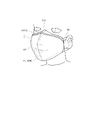
- FIG. 1 is a side view of the mask in a folded state according to the first embodiment.
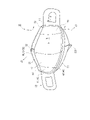
- FIG. 2 is a perspective view seen from the outside of the mask in the unfolded state according to the first embodiment.
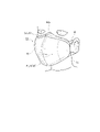
- FIG. 3 is a perspective view seen from the inside of the mask in the unfolded state according to the first embodiment.
- FIG. 4 is a diagram showing a wearing state of the mask according to the first embodiment.
- FIG. 5 is a schematic cross-sectional view of a mask.
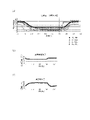
- FIG. 6 schematically shows the relationship between the length (A) of the covering portion of the mask in the extended state and the shortest length (B) of the upper and lower support portions, and the distance (L3) between the virtual line and the apex of the protrusion. It is a diagram.
- FIG. 6 schematically shows the relationship between the length (A) of the covering portion of the mask in the extended state and the shortest length (B) of the upper and lower support portions, and the distance (L3) between the virtual line and the apex of the
- FIG. 7 is a diagram showing antifogging evaluation.
- FIG. 8 is a side view of the mask in the folded state according to the sixth embodiment.
- FIG. 9 is a perspective view seen from the outside of the mask in the deployed state according to the sixth embodiment.
- FIG. 10 is a perspective view seen from the inside of the mask in the deployed state according to the sixth embodiment.
- FIG. 11 is a diagram showing a wearing state of the mask according to the sixth embodiment.
- FIG. 12 is a schematic cross-sectional view of the mask of the sixth embodiment.
- a mask according to one aspect has a covering portion that covers the wearer's mouth and is made of a film having a light transmittance of 80% or more.
- the humidity is changed from 30% to 70% 200 times at intervals of 3 seconds, and the humidity is changed from 70% to 30% after the fogging process.
- the compression anti-fogging index at humidity of 70% or higher of the cover is 15 or higher.
- the mask of this embodiment has a compression anti-fogging index of 15 or more in an environment with a humidity of 70% or more.
- the compression anti-fogging index is 15 or more, it is easy to ensure visibility on the back side through the cover portion. According to this aspect, it is possible to ensure the visibility of the facial expression under the usage environment of the mask.
- the compression antifogging index of the cover portion in the antifogging evaluation is 15 or more for 300 consecutive seconds or more. According to this aspect, the visibility of the covering portion can be ensured beyond 300 seconds, which is a temporary break of the conversation. Therefore, the visibility of facial expressions during conversation can be maintained.
- the minimum value of the compression antifogging index of the cover portion in the antifogging evaluation is 15 or more. According to this aspect, the visibility of the cover portion can always be ensured.
- the difference between the minimum value and the maximum value of the compression antifogging index of the cover portion in the antifogging evaluation is 25 or less. According to this aspect, since the difference between the maximum value and the minimum value of the compression anti-fogging index is small, there is little change in the visibility of the cover portion. Compared to the form in which the visibility of the covering part changes greatly, it is possible to continue to grasp the expression of the face without discomfort.
- the cover portion has a film layer composed of the film, and an anti-fogging layer disposed on the skin surface side of the film layer.
- the thickness of the antifogging layer is 5 ⁇ m or less, preferably 2 ⁇ m or less.
- the antifogging layer is arranged on the skin side of the film, and the antifogging effect can be exhibited on the surface where fogging occurs, and the effect can be easily obtained.
- the thickness of the anti-fogging layer is 5 ⁇ m or less, and the thickness of the anti-fogging layer is substantially close to 0 mm, so that the influence on visibility can be suppressed.
- the support portion has a support portion that supports the cover portion.
- the rigidity of the support portion is lower than the rigidity of the cover portion.
- the support portion is composed of a base fabric.
- the support portion is made of the base fabric and has higher breathability than the cover portion. Therefore, water vapor in the mask can be easily released to the outside through the support portion, and fogging of the cover portion can be reduced.
- the rigidity of the supporting portion is lower than that of the covering portion, the supporting portion tends to act as a cushioning area when the face moves. To prevent the cover from following the movement of the face too much, and to easily secure the visibility of the cover.
- the area of the region where the support part and the cover part overlap is 20% or less of the area of the cover part in the stretched state in which the cover part is stretched in the cross direction. According to this aspect, it is possible to reduce the area of covering the covering portion with the supporting portion, that is, the area that hinders visibility. Therefore, it is easier to ensure the visibility of the cover portion.
- the cheek rest portion has a cheek rest portion positioned on the skin surface side of the cover portion and in contact with the wearer's cheek.
- the stiffness of the cheek rest is lower than the stiffness of the cover.
- the said cheek rest part is comprised by the base fabric. According to this aspect, it is difficult for the covering portion to directly hit the cheek, and discomfort due to the direct contact of the covering portion against the cheek when worn can be suppressed.
- the stiffness of the cheek pad is lower than that of the cover, the cheek pad easily acts as a cushioning area. By acting as a cushioning area for the cheek pad, it is possible to prevent the cover from following the movement of the face too much.
- the cheek rest part is made of base fabric and has higher breathability than the cover part. Therefore, even if the cheek part directly touches the skin, it is possible to prevent the cheek part from coming into close contact with the skin due to water vapor or the like.
- it has a support part that supports the cover part, and a cheek support part that is positioned on the skin surface side of the cover part and contacts the wearer's cheek.
- the area of the region where at least one of the support portion and the cheek rest portion overlaps with the cover portion is 40% or less of the area of the cover portion in the stretched state in which the cover portion is stretched in the cross direction. According to this aspect, it is possible to reduce the area that covers the covering portion with at least one of the support portion and the cheek rest portion, that is, the area that hinders visibility. Therefore, it is easier to ensure the visibility of the cover portion.
- the mask may be a disposable mask intended for one-time use or a multiple-use mask.
- the same or similar reference numerals are given to the same or similar parts.
- the drawings are schematic and the ratio of each dimension may differ from the actual one. Therefore, specific dimensions and the like should be determined with reference to the following description.
- FIG. 1 to 5 are diagrams showing configuration examples of the mask 1 according to the first embodiment.
- FIG. 1 is a side view of a folded mask in which the mask is folded in half.
- 2 is a perspective view of the mask 1 in the unfolded state viewed from the outer surface side (non-skin surface side) Z2
- FIG. 3 is a perspective view of the unfolded mask 1 viewed from the inner surface side (skin surface side) Z1.
- FIG. 4 is a diagram showing how the mask according to the embodiment is worn.
- FIG. 5 is a schematic cross-sectional view of a mask.
- FIG. 5A is a schematic cross-sectional view taken along line AA shown in FIG.
- FIG. 5B is a cross-sectional view taken along line CC shown in FIG.
- the mask 1 has a covering portion 10 that covers at least the mouth of the wearer. It has an up-down direction X extending above and below the wearer's face and a cross direction Y perpendicular to the up-down direction X.
- the cross direction Y extends to the left and right sides of the wearer's face.
- the upper end edge and the lower end edge in the present invention are the edges located outside the vertical direction X, and the upper end portion and the lower end portion are constant in the vertical direction X including the edges located outside the vertical direction X.
- the outer edge in the present invention is an outer edge in the cross direction Y, and the outer portion is a portion occupying a certain range in the cross direction Y including the outer edge in the cross direction Y.
- the inner edge is an inner edge in the cross direction Y, and the inner portion is a portion occupying a certain range in the cross direction Y including the inner edge in the cross direction Y.
- the cover part 10 is made of a film with a light transmittance of 80% or more.
- the covering part 10 is configured to cover at least the mouth of the wearer, and may be configured to cover both the nose and the mouth.
- the cover part 10 may be folded with a body fold line FL10 extending along the vertical direction X at the center of the cross direction Y of the cover part 10 as a base point.
- the body fold line FL10 is a fold line for folding the cover portion 10 so that the inner surfaces of the cover portion 10 face each other. Therefore, the cover portion 10 is formed with a valley fold when viewed from the inner surface side Z1.
- the covering part 10 may be made of a single piece of material that is continuous in the cross direction Y. As shown in FIG.
- the cover portion is not composed of a single film, but has a left half sheet and a right half sheet, and the left half sheet and the right half sheet are formed at the center of the cover portion 10 in the cross direction Y. It may be joined. In the form in which the left half sheet and the right half sheet are joined, the joint is provided at the center of the cover part 10 in the cross direction Y, and the visibility of the cover part 10 is lowered. A joint portion of the cover portion 10 may constitute a low transparency portion, which will be described later. Also, in another embodiment, the mask 1 may be unfolded and unfolded prior to use. The cover 10 may be vacuum formed.
- the cover part 10 has a light transmittance of 80% or more and is substantially transparent. Incidentally, the light transmittance may be measured by a well-known method. For example, it can be measured in accordance with JIS K 7375 using a colorimetric color difference meter manufactured by Nippon Denshoku Industries Co., Ltd. or equivalent.
- the cover part 10 has an outer edge that forms the outer shape of the cover part 10 .
- the outer edges include a pair of outer edges 11 extending in the vertical direction X at the edges of the cover portion 10 in the cross direction Y, an upper edge 12 extending in the cross direction Y at the upper end of the cover portion 10, and a cross direction at the lower end of the cover portion 10. and a lower edge 13 extending in Y.
- the form extended in one direction is a concept including not only the structure parallel to one direction but the structure less than 45 degrees with respect to one direction.
- the mask 1 may have a support portion 20.
- the support portion 20 supports the cover portion 10 .
- the support portion 20 has upper and lower support portions.
- the vertical support part can stand up against the end part of the cover part 10 in the vertical direction X, and is arranged at least one of the upper side and the lower side with respect to the mouth when worn.
- the upper and lower support portions can stand up against the upper end portion of the cover portion 10, and can stand up against the upper support portion 22 arranged above the mouth when worn and the lower end portion of the cover portion 10, and can stand up against the lower end portion of the cover portion 10 when worn. and a lower support portion 23 arranged below the mouth.
- the vertical support part of the present embodiment has both the upper support part 22 and the lower support part 23
- the vertical support part may be either the upper support part 22 or the lower support part 23
- the structure in which the upper and lower support parts stand up may be a structure in which the upper and lower support parts stand up toward the skin surface side Z1 with respect to the cover part 10 when worn, and the upper and lower support parts stand up by unfolding the folded mask before use.
- the configuration may be such that the upper and lower support portions stand up from the beginning in the unfolded state (the state in which the covering portion of the mask is not folded) before use.
- the support part 20 may have a side support part 21 that covers at least part of the outer edge 11 of the cover part 10 .
- the side support portion 21 may cover the entire outer edge 11 of the cover portion 10 . According to this configuration, it is possible to prevent the outer edge 11 from digging into the face over the entire area of the outer edge 11 of the cover portion 10 .
- the side support portion 21 may also be continuous in the vertical direction X. In another embodiment, when the outer edge 11 of the cover portion 10 is separated in the vertical direction X, the side support portions 21 may also be separated in the vertical direction X and provided.
- the breathability of the support part 20 may be higher than the breathability of the cover part 10 .
- the cover part 10 is made of a film and has relatively low air permeability.
- the support portion 20 is made of, for example, nonwoven fabric, woven fabric, or urethane, and has relatively high air permeability. Therefore, even if the mouth is covered with the cover part 10 made of a film, breathability can be ensured via the support part 20 that supports the cover part, and breathing of the wearer can be ensured.
- the light transmittance of the cover portion 10 may be higher than the light transmittance of the support portion 20 .
- the mask 1 may have an ear hook portion 30 that is hooked on the wearer's ear.
- the ear hook portion 30 may continue to at least one of the support portion 20 and the cover portion 10 .
- the ear hooking portion 30 may be connected to both sides of the supporting portion 20 in the cross direction Y. As shown in FIG. Each ear hook 30 hooks behind the wearer's ear.
- the inner portion 33 of the ear hook portion 30 is connected to the outer portion of the support portion 20 .
- the inner portion 33 of the ear hook portion 30 may be continuous in the vertical direction X between the upper edge 31 of the inner portion 33 and the lower edge 32 of the inner portion 33 . are spaced apart from each other and may be connected to the support portion 20 respectively.
- the outer portion 34 of the ear hook 30 is configured to hook behind the wearer's ear. In a state in which both the pair of ear hooks 30 are put on the ears, the outer part of the cover part 10 and the support part 20 are pulled outward in the cross direction Y, and the cover part 10 covers the wearer's mouth. state is maintained.
- the ear hooking portion 30 may be formed by a sheet member made of nonwoven fabric or the like, and may be formed by a notch 35 formed in the sheet member, or may be formed by a cord-like elastic member.
- the upper support part 22, the lower support part 23 and the side support part 21 may be integrated with the same material. According to this configuration, the upper support portion 22, the lower support portion 23, and the side support portions 21 are easily interlocked, and the upper support portion 22, the lower support portion 23, and the side support portions 21 cooperate to fit the cover portion to the face. It becomes easier to let The support portion 20 and the cover portion 10 are joined to each other by the body joint portion 40 .
- the body joint portion 40 may be configured by at least one of sewing, ultrasonic waves, heat sealing, and adhesive.
- the main body joint portion 40 of the present embodiment is constructed by sewing, and seams are formed.
- the body joint portion 40 includes a side body joint portion 41 that joins the cover portion 10 and the side support portion 21, an upper body joint portion 42 that joins the upper support portion 22 and the cover portion 10, and the cover portion 10 and the lower support portion. and a lower body joint 43 that joins the lower body 23 .
- the side body joint portion 41 may join the ear hook portion 30 together with the cover portion 10 and the side support portion 21 . This makes it easier for the side support portion 21 and the cover portion 10 to interlock with the ear hook portion 30 .
- two upper body joint portions 42 may be provided at the upper end portion of the cover portion 10 at intervals in the vertical direction X.
- the upper support part 22 is folded on the non-skin surface side Z2 from the cover part 10 with the upper fold line 22F as a base point, and arranged in two layers. As will be described later, the upper support portion 22 is folded back toward the skin surface side Z1 with the upper edge of the cover portion 10 as a base point. A portion of the upper support portion 22 that is folded back from the upper edge of the cover portion 10 and extends beyond the upper edge of the cover portion 10 constitutes an upper folded portion 225 to be described later.
- the first upper body joint portion 42 joins the upper support portion 22 and the cover portion 10 in one layer, and serves as the folding base point of the upper fold line 22F.
- the second upper body joint portion 42 is arranged above the first upper body joint portion 42 and includes two layers of the upper support portion 22 (the portion where the upper support portion 22 is folded and arranged in two layers).
- the cover part 10 is joined.
- only one upper body joint portion 42 may be provided at the upper end portion of the cover portion 10, or only the first upper body joint portion of the present embodiment may be provided, or two upper body joint portions may be provided. Only the first upper body joint may be provided.
- two lower body joint portions 43 may be provided at the lower end portion of the cover portion 10 at intervals in the vertical direction X. As shown in FIG.
- the lower support part 23 is folded on the non-skin surface side Z2 from the cover part 10 with the lower fold line 23F as a base point, and arranged in two layers. Further, the lower support portion 23 is folded back toward the skin surface side Z1 with the lower edge 13 of the cover portion 10 as a base point, as will be described later. A portion of the lower support portion 23 that is folded back from the lower edge of the cover portion 10 and extends beyond the lower edge 13 of the cover portion 10 constitutes a lower folded portion 235 to be described later.
- the first lower body joint portion 43 joins the lower support portion 23 of one layer and the cover portion 10, and serves as a folding base point of the lower fold line 23F.
- the second lower body joint portion 43 is arranged below the first lower body joint portion 43, and includes two layers of the lower support portion 23 (the portion where the lower support portion 23 is folded and arranged in two layers) and the cover. joins the parts.
- only one lower body joint portion 43 may be provided at the lower end portion of the cover portion 10, and only the first lower body joint portion of the present embodiment may be provided, or the second lower body joint portion may be provided. Only the upper body joint may be provided.
- the second upper body joint portion 42 and the second lower body joint portion 43 may be provided along the outer edge of the cover portion 10 one round inside the outer edge, more specifically, 1 to 5 mm inside.
- the mask 1 of the present embodiment is configured so that the cover portion 10 and the upper and lower support portions can be easily formed in appropriate shapes.
- the upper and lower support portions and the cover portion 10 are in contact with each other at the upper and lower contact portions (see FIG. 5A) in the wearing state.
- the upper/lower contact portion 50 may be a portion where the upper/lower support portion and the cover portion 10 are in contact with each other in the wearing state.
- the upper and lower support portions stand up with respect to the cover portion with any edge of the upper and lower contact portions 50 as a base point. Therefore, the vertical contact portion constitutes a starting point of the vertical support portion.
- the vertical contact portion 50 has a first contact position P1, which is one outer edge of the vertical contact portion 50 in the cross direction Y, and a second contact position P1, which is the other outer edge of the vertical contact portion 50 in the cross direction Y. and a contact position P2.
- one outer edge in the cross direction Y is a right outer edge located on the right side when the mask 1 is viewed from the front
- the other outer edge in the cross direction Y is the left side when the mask is viewed from the front. is the left lateral edge located at
- the first contact position P1 is the upper first contact point where the right outer edge of the upper support portion 22 and the cover portion 10 are in contact.
- It includes a contact position P11 and a lower first contact position P12 where the right outer edge of the lower support portion 23 and the cover portion 10 are in contact, and the second contact position P2 is the left outer edge of the upper support portion 22. and a lower second contact position P22 where the cover portion 10 and the left outer edge of the lower support portion 23 contact.
- the shortest length (B) of the upper and lower support portions extending between the first contact position P1 and the second contact position P2 is the first contact position P1.
- the second contact position P2. 6 schematically shows the relationship between (A) and (B) of the mask 1 in the stretched state with reference to the cross section along line BB shown in FIG.
- the length (A) of the cover portion 10 is not the distance between the first contact position P1 and the second contact position P2 in the extended state, but the length of the cover portion 10 from the first contact position P1 to the second contact position P2. is the length of Specifically, the length (A) is, as shown in FIG. It is the total length of A2 and .
- (A) and (B) show the length of the cover portion 10 between the upper first contact position P11 and the upper second contact position P21, and the distance between the upper first contact position P11 and the upper second contact position P21. , and compare the length of the cover portion 10 between the lower first contact position P12 and the lower second contact position P22, and the distance between the lower first contact position P12 and the lower second contact position P22. . Further, the shortest length (B) of the vertical support portion is the shortest length of the vertical support portion extending between the first contact position P1 and the second contact position P2 in the extended state. It is replaced by the distance between P1 and the second contact position P2.
- the shortest length (B) of the upper support portion 22 ⁇ the length (A) of the cover portion 10 and the shortest length (B) of the lower support portion 23 ⁇ the length of the cover portion 10 are satisfied. At least one of (A) and (A) may be satisfied. Even if the upper and lower support portions and the cover portion 10 are in contact with each other such that the portion where the upper and lower support portions and the cover portion 10 contact each other has a predetermined width, the first contact position P1 and the second contact position P1 may be different.
- the shortest length of the upper and lower support portions extending between the contact positions P2 may be the distance in the cross direction Y between the outer edge of the first contact position P1 and the outer edge of the second contact position P2.
- the length of the cover portion extending between the first contact position P1 and the second contact position P2 is the length of the cover portion between the outer edge of the first contact position P1 and the outer edge of the second contact position P2. It may be the length of the cross direction Y along.
- the wearer when wearing the mask 1, the wearer forms the covering portion 10 in an elongated state in the cross direction Y so as to cover the mouth with the mask 1 and put the mask 1 on both ears. Wear 1. Therefore, the "stretched state" of the present invention is a state similar to a state in which the wearer pulls the mask 1 in the cross direction Y when wearing it. 10 from the outer edge of 10 to the inner side of the cross direction) is held by the upper and lower chucks of a tensile tester (such as Autograph AGS-X manufactured by Shimadzu Corporation), and the upper and lower chucks are separated. By widening the gap, the cover portion 10 is pulled at 2.0N.
- a tensile tester such as Autograph AGS-X manufactured by Shimadzu Corporation
- the upper and lower support portions maintain the distance between the ends of the cover portion 10 in the cross direction Y, and the cover portion 10 is configured to maintain a three-dimensional shape without becoming flat.
- the extended state if the shortest length (B) of the upper and lower support portions and the length (A) of the cover portion 10 are the same, the area between the first contact position P1 and the second contact position P2 is , in the extended state, both the upper and lower support parts and the cover part 10 have the same length and are planar.
- the shortest length (B) of the upper and lower support portions is shorter than the length (A) of the cover portion 10 . Therefore, in the extended state, when the upper and lower support portions are stretched flat in the region between the first contact position P1 and the second contact position P2, the cover portion 10 assumes a curved or bent three-dimensional shape. Further, the vertical support portion extends so as to connect the first contact position P1 and the second contact position P2 of the three-dimensional cover portion 10 and rises from the end portion of the cover portion 10 in the vertical direction X. As shown in FIG.
- the cover 10 can be three-dimensionally formed and the upper and lower support parts can be erected from the cover 10 by a general operation at the time of wearing, that is, the operation of extending the cover 10 .
- the wearer can form the mask 1 into an appropriate shape without being conscious of it, and can improve sealing performance while securing a space around the mouth.
- the contact position can be defined by the position at which the support portion 20 contacts the upper edge (or lower edge) of the cover portion 10 .
- the upper support part 22 has a configuration in which the standing member and the member connected to the cover part 10 are separate and connected to each other, the upper support part 22 is connected to the cover part 10.
- the contact position is the position where the member and the cover portion 10 are connected. That is, the member itself that stands on the wearer's side may not be directly connected to the cover portion 10, and if the member that stands on the wearer side is connected to the cover portion 10 via another member, other The position where the member and the cover portion 10 are connected becomes the contact position.
- the first contact position P1 and the second contact position P2 may be provided on the outer edge in the cross direction Y of the outer edge in the vertical direction X of the cover part 10 . More specifically, the upper first contact position P11 is provided on the right edge of the upper edge 12 of the cover portion 10, and the upper second contact position P21 is provided on the left edge of the upper edge 12 of the cover portion 10. you can The lower first contact position P12 may be provided at the right edge of the lower edge 13 of the cover portion 10, and the lower second contact position P22 may be provided at the left edge of the lower edge 13 of the cover portion 10. According to this configuration, the entire edge of the covering portion 10 in the vertical direction X can be covered by the vertical support portion extending between the first contact position P1 and the second contact position P2.
- the sealing performance of the mask 1 can be improved.
- the first abutment position P1 and the second abutment position P2 are located closer to the outer edge in the cross direction Y than the outer edge in the vertical direction X of the cover portion 10 (upper edge 12 and lower edge 13). It may be arranged inside the cross direction Y. That is, a partial region of the cover portion 10 in the cross direction Y may be formed into a curved shape by the upper and lower support portions.
- the ear hook portion 30 may be connected to at least one of the support portion 20 and the cover portion 10 at the connection position P3.
- the connecting position P3 may have a right connecting position P31 positioned on the right side in front view and a left connecting position P32 positioned on the left side in front view.
- FIG. 5B is a cross-sectional view taken along line CC shown in FIG.
- the ear hooking portion 30 is folded outward in the cross direction Y with the side crease 30F as a base point on the non-skin surface side Z2 of the covering portion 10 .
- a portion of the ear hook portion 30 that is not folded back around the side fold 30 ⁇ /b>F (a portion in contact with the cover portion 10 ) and the cover portion 10 are joined by a side body joining portion 41 .
- the portion that is folded back from the side fold line 30F and extends outward in the cross direction Y from the outer edge 11 of the cover portion 10 is arranged outside the cover portion when worn, and is placed on the wearer's cheeks and ears. be guessed.
- the connection position P3 in the present embodiment is the position of the side body joint portion 41 .
- the ear hook part of the present embodiment is connected to the support part 20 (upper and lower support parts and side support parts) at both the right connection position P31 and the left connection position P32.
- the cover portion 10 can be pulled through the support portion 20, and the cover portion 10 and the upper and lower support portions can be formed in a three-dimensional shape.
- the position of the connecting position P3 in the cross direction Y coincides with the first contact position P1 and the second contact position P2, or is positioned inside the cross direction Y of the first contact position P1 and the second contact position P2.
- the upper and lower supporting parts can be erected over the region extending between the first contact position P1 and the second contact position P2, and the cover part 10 can be formed in a three-dimensional shape.
- the ear hook part 30 may be connected to both the upper and lower support parts and the cover part 10 at the connecting position P3.
- the ear hooking part 30 By pulling the ear hooking part 30 in the cross direction Y, the upper and lower support parts and the cover part 10 can be pulled in the cross direction Y through the ear hook part 30, and the cover part 10 and the upper and lower support parts are extended.
- the cover part 10 and the upper and lower support parts can be formed in a three-dimensional shape.
- the ear hook part 30 may be connected to the upper and lower support parts, the cover part 10 and the cheek rest part 60 at the connecting position P3.
- the side support part 21 may be arranged on the non-skin surface side Z2 of the cover part 10 and connected to the ear hook part 30 .
- the side support part 21 and the covering part 10 can be pulled toward the face, and the outer edge 11 of the covering part 10 can be brought into close contact with the face.
- the side supporting portion 21 and the ear hooking portion 30 are made of the same material. You can The positional relationship between the ear hook portion 30 and the side support portion 21 is not limited, and the ear hook portion 30 may be arranged on the skin surface side Z1 of the side support portion 21, or may be arranged on the non-skin surface side Z2 of the side support portion 21. The ear hook portion 30 may be arranged in the . Alternatively, the outer edge 11 of the cover 10 may be supported only by the ear hooking portion 30 without the side support portion 21 covering the outer edge 11 of the cover 10 .
- a tuck portion may be formed to shorten the length in the cross direction Y of the upper and lower support portions.
- the tuck portion may have an upper tuck portion 221 provided on the upper support portion 22 and a lower tuck portion 231 provided on the lower support portion 23 .
- the upper tuck portion 221 is formed by joining the upper support portions 22 together.
- the lower support portions 23 are formed by joining the lower support portions 23 together.
- the tuck portion is formed by sewing.
- the tuck portion may be positioned on the non-skin surface side Z2 of the upper and lower support portions in the stretched state.
- the upper tuck portion 221 is arranged above the upper support portion 22, and the lower tuck portion 231 is arranged below the lower support portion 23.
- the wearer grasps the tuck portion located on the non-skin surface side Z2 with respect to the upper and lower support parts to adjust the position of the upper and lower support parts. and standing position can be adjusted.
- the tuck portion may extend in the height direction extending to the skin surface side Z1 and the non-skin surface side Z2 in the upright state of the upper and lower support portions.
- the tuck portion serves as a base point for supporting the upright state of the upper and lower support portions, making it easier to maintain the upright state of the upper and lower support portions.
- the tuck portion may be arranged in the center of the cross direction Y of the cover portion 10 . The wearer can easily grasp the position of the center of the mask 1 in the cross direction Y using the tuck portion as a mark, and can easily wear the mask 1 more appropriately.
- the length of the tuck portion in the cross direction Y may be longer toward the side away from the cover portion 10 (the skin surface side Z1 in the standing state).
- the length of the vertical support portion in the cross direction Y becomes shorter toward the side away from the edge of the cover portion 10 in the vertical direction X when the vertical support portion is in an upright state. Therefore, when the face is covered with the upper and lower support parts, the upper and lower end parts of the mask (the upper and lower support parts in an upright state) can be easily brought into close contact with the face, and the gap between the face and the mask can be reduced.
- the upper and lower support parts may have a nose fit member at a portion corresponding to the nose when worn.
- the upper and lower support parts may be joined to the non-skin surface side Z2 of the cover part 10 and folded back toward the outside of the cover part 10 .
- the upper and lower support portions may not be in contact with the non-skin surface of the cover portion 10, and may be joined to the non-skin surface side Z2 of the cover portion 10 via another member.
- the upper and lower support portions of the present embodiment are in contact with the non-skin surface of the cover portion and are joined by sewing. More specifically, the upper support portion 22 is joined to the non-skin surface side Z2 of the upper end portion of the cover portion 10 .
- the upper support portion 22 has an upper folded portion 225 folded back toward the non-skin surface side Z2 with the upper main body joint portion 42 located inside the outer edge of the cover portion 10 as a base point.
- the upper folded portion 225 is folded toward the outside of the cover portion 10 and extends beyond the outer edge of the cover portion 10 .
- the upper folded part 225 stands up on the skin surface side Z1 with respect to the cover part 10 when worn, and is arranged so as to cover the upper side of the mouth.
- the lower support portion 23 is joined to the non-skin surface side Z2 of the lower end portion of the cover portion 10 .
- the lower support portion 23 has a lower folded portion 235 folded back toward the non-skin surface side Z2 with the lower body joint portion 43 located inside the outer edge of the cover portion 10 as a base point.
- the lower folded portion 235 is folded toward the outside of the cover portion 10 and extends beyond the outer edge of the cover portion 10 .
- the lower folded part 235 stands up on the skin surface side Z1 with respect to the cover part 10 when worn, and is arranged so as to cover the lower side of the mouth.
- the outer edge of the cover portion 10 in the vertical direction X can be covered by the upper folded portion 225 and the lower folded portion 235 . Therefore, the airtightness at the ends of the mask in the vertical direction X can be improved.
- the length of the lower folded portion 235 in the vertical direction X may be longer than the length of the upper folded portion 225 in the vertical direction X (height direction when standing). According to this configuration, it is easy to cover the chin of the wearer with the mask, and it is possible to suppress the displacement of the mask caused by the movement of the mouth.
- the mask 1 of the present embodiment is configured to easily ensure the visibility of not only the mouth but also the area around the mouth.
- the ratio of the maximum length (L2) of the covering portion 10 in the vertical direction X to the maximum length (L1) of the covering portion 10 in the cross direction Y is 0.3 or more.
- the maximum length of the cover 10 in the cross direction Y is designed to cover the mouth and part of the cheeks
- the maximum length of the cover 10 in the vertical direction X is the mouth and cheeks. It is designed to be long enough to cover part of the nose.
- wearers who use sign language such as hearing-impaired wearers, childcare workers, and caregivers, who need to convey facial expressions to the other party, convey information not only by the mouth but also by the movement of the entire face. If the area of the cover part 10 is not sufficient, information may not be conveyed accurately and appropriately even if the cover part 10 is transparent. As a result of intensive research by the applicant, it was found that unless the height of the covering portion 10 in the vertical direction X is sufficient, the visibility of the entire cheek cannot be ensured, and it is difficult to convey information accurately and appropriately.
- the ratio of the maximum length (L2) of the cover portion 10 in the vertical direction X to the maximum length (L1) of the cover portion 10 in the cross direction Y is 0.3 or more. It is easy to sufficiently secure the length of the vertical direction X of 10, and the visibility of not only the mouth but also the periphery of the mouth such as cheeks can be secured by the cover part 10. ⁇ Therefore, it becomes easy to convey information accurately and appropriately. From the viewpoint of ensuring the visibility around the mouth by the cover part 10, the maximum dimension of the cover part 10 in the cross direction Y may be 180 mm or more and 220 mm or less, and the maximum dimension of the cover part 10 in the vertical direction X is 90 mm.
- the area of the covering portion 10 in which the vertical direction X is 90 mm or more may be 50% or more of the entire area of the covering portion 10 in the cross direction Y, and may be 90 mm or more.
- a protruding part 15 is provided at the center of the cover part 10 in the cross direction Y and protrudes toward the non-skin surface side Z2 from both edges of the cover part 10 in the cross direction Y. It is The protruding portion 15 only needs to protrude toward the non-skin surface side Z2 from the imaginary line EL (see FIG. 6) connecting both outer edges of the cover portion 10 in the cross direction. It may be formed over the cover portion 10 or may be formed in a part of the cover portion 10 in the cross direction Y. The center of the cover portion 10 in the cross direction Y may be the central area of the cross direction Y of the cover portion 10 divided into three equal parts.
- the projecting portion 15 may be arranged in at least part of the central region, and may be arranged beyond the central region in the cross direction. Moreover, the projecting portion 15 may straddle the center of the cross direction Y of the cover portion 10 or may not straddle the center of the cross direction Y of the cover portion 10 .
- the apex 15P of the projecting portion 15 is the point at which the projecting portion 15 protrudes most toward the non-skin surface side Z2, and may be arranged in the center of the cross direction Y of the cover portion 10, or may be displaced from the center of the
- the apex 15P of the projecting portion 15 of the present embodiment is provided on the body fold line FL10.
- the distance (L3) between the apex 15P of the projecting portion 15 and the imaginary line EL connecting both outer edges of the covering portion 10 in the cross direction Y is 15 mm or more.
- the imaginary line EL may be a line that connects the outermost points of the outer edges of the cover 10 in the cross direction.
- the distance between the virtual line EL and the vertex 15P of the projecting portion 15 is the distance between the inner surface of the cover portion at the vertex 15P of the projecting portion 15 and the virtual line EL connecting both outer edges of the inner surface of the cover portion 10 in the cross direction Y. , corresponds to the length of the space surrounded by the cover 10 in the depth direction.
- a wearer generally wears the mask 1 while forming the covering part 10 in an extended state extending in the cross direction Y in order to cover the mouth with the mask 1 and put the mask 1 on both ears when wearing it. .
- the distance between the apex of the projecting portion and the virtual line EL connecting both outer edges of the covering portion 10 in the cross direction Y is 15 mm or more. It makes it easier to convey facial expressions without hindering movement.
- the area of the region where the upper support part 22 and the cover part 10 overlap in the stretched state may be 20% or less of the area of the cover part 10 . According to this configuration, it is possible to reduce the area covered by the upper support portion 22 on the cover portion 10, that is, the area that hinders visibility. Therefore, it is easier to ensure the visibility of the cover portion 10 .
- the area where the upper support part 22 and the cover part 10 overlap is the area where the upper support part 22 and the cover part 10 overlap when the mask 1 in the stretched state is viewed from the front. In the overlapping region, the upper support part 22 and the cover part 10 may be joined, the upper support part 22 and the cover part 10 may be in contact without being joined, or the upper support part 22 and the cover part may be in contact with each other.
- the cover portion 10 may be spaced apart. Further, the area of the region of the upper and lower contact portions that overlaps the upper support portion 22 and the cover portion 10 may be 20% or less, more preferably 10% or less, of the area of the cover portion 10 . According to this configuration, it is possible to secure an area where the upper support portion 22 and the cover portion 10 are not in contact with each other, thereby further improving visibility through the cover portion 10 .
- the upper support part 22 is joined to the non-skin surface side Z2 of the cover part 10 and is folded back toward the outside of the cover part 10 . Since the upper support part 22 is folded back and stands on the skin surface side Z1 when worn, it is easy to ensure the standability with respect to the cover part 10 . By erecting the upper supporting portion 22 with respect to the covering portion 10, the area covered by the covering portion 10 with the upper supporting portion 22, that is, the area that obstructs visibility can be reduced. Therefore, it is easier to ensure the visibility of the cover portion 10 .
- the rigidity of the upper support portion 22 may be lower than that of the cover portion 10 .
- the upper support part 22 Since the rigidity of the upper support part 22 is lower than that of the cover part 10, the upper support part 22 tends to act as a cushioning area when the face moves. Therefore, the cover 10 is prevented from following the movement of the face too much, and the visibility of the cover 10 is easily ensured.
- the standing height of the upper support part 22 in the extended state may be 25 mm or more.
- the standing height of the upper support portion 22 is the height extending vertically from the cover portion 10 in the extended state. It is sufficient that the highest standing height of the upper support portion 22 is 25 mm or more. Since the upright height of the upper support part 22 is 25 mm or more, the top of the nose can be easily covered with the upper support part 22 . A distance between the cover part 10 and the face is ensured, and the cover part 10 hardly hits the face directly when the face moves. Therefore, it is possible to prevent the cover from excessively following the movement of the face, and it is easy to ensure the visibility of the cover 10 . More preferably, the standing height of the upper support portion 22 in the extended state may be 35 mm or more.
- the area of the region where the lower support part 23 and the cover part 10 overlap in the stretched state may be 20% or less of the area of the cover part 10 .
- the area covered by the cover portion 10 with the lower support portion 23, that is, the area that hinders visibility can be reduced. Therefore, it is easier to ensure the visibility of the cover portion 10 .
- 80% or more of the cover part does not overlap the lower support part 23, and visibility can be secured over a wide range of the cover part 10. ⁇
- the region where the lower support portion 23 and the cover portion 10 overlap is the region where the lower support portion 23 and the cover portion 10 overlap when viewed from the front of the stretched mask.
- the lower support portion 23 and the cover portion 10 may be joined, the lower support portion 23 and the cover portion 10 may be in contact without being joined, or the lower support portion 23 and the cover portion may be in contact with each other. 10 may be spaced apart. Further, the area of the region of the upper and lower contact portions that overlaps the lower support portion 23 and the cover portion 10 may be 20% or less, more preferably 10% or less, of the area of the cover portion 10 . According to this configuration, it is possible to secure an area where the lower support portion 23 and the cover portion 10 are not in contact with each other, thereby further improving the visibility through the cover portion 10 .
- the total area of the overlapping area of the upper support part 22 and the cover part 10 and the overlapping area of the lower support part 23 and the cover part 10 may be 30% or less of the area of the entire cover part, More preferably, it may be 20% or less.
- the area where the support portions (upper support portion 22, side support portion 21) and the cover portion 10 overlap may be 30% or less, more preferably 20% or less, of the entire area of the cover portion. . Since there is little area where the entire support portion overlaps the cover portion, visibility of the cover portion can be more easily ensured.
- the lower support part 23 is joined to the non-skin surface side Z2 of the cover part 10 and folded back toward the outside of the cover part. Since the lower support portion is folded back and stands on the skin surface side Z1 when worn, it is easy to secure the standing property with respect to the cover portion 10 . By erecting the lower support part 23 with respect to the cover part 10, the area covered by the lower support part 23 on the cover part 10, that is, the area that hinders visibility can be reduced. Therefore, it is easier to ensure the visibility of the cover portion 10 .
- the rigidity of the upper support portion 22 may be lower than that of the cover portion 10 .
- the lower support part 23 Since the rigidity of the lower support part 23 is lower than that of the cover part 10, the lower support part 23 tends to act as a cushioning area when the face moves. Therefore, the cover 10 is prevented from following the movement of the face too much, and the visibility of the cover 10 is easily ensured.
- the standing height of the lower support part 23 in the extended state may be 25 mm or more.
- the standing height of the lower support portion 23 is the height extending vertically from the cover portion 10 in the extended state. It is sufficient that the highest standing height of the lower support portion 23 is 25 mm or more. Since the standing height of the lower support part 23 is 25 mm or more, the lower support part 23 can easily cover the chin. In addition, since the distance between the covering part 10 and the face can be secured, the covering part 10 does not come into direct contact with the face when the face moves. Therefore, the cover 10 is prevented from following the movement of the face too much, and the visibility of the cover 10 is easily ensured. More preferably, the standing height of the upper support in the extended state may be 35 mm or more. The standing height of the lower support 23 may be higher than the standing height of the upper support 22 .
- the color of the support portion 20 may be a color that easily blends in with the skin.
- the colors of the support portion 20 are beige (#FFB74C), brown (#994C00), orange (#FFB74C), ocher (#c39143), ocher (#CC7722), orange (#f39800), Can be cream (#FFEDB3), bisque (#FFE4C4), honey (#e7bb5e), caramel (#90692c), walnut (#a86f4c).
- a color having a color difference ⁇ E of 20.0 or less with respect to the color concerned may be regarded as the same color as the color concerned. More preferably, a color with a color difference ⁇ E of 12.0 or less with respect to the color may be included.
- the difference in L* value between two points to be measured is ⁇ L*
- the difference in a* is ⁇ a*
- the difference in b* value is ⁇ b*
- color difference ⁇ E [( ⁇ L*) 2 +( ⁇ a*) 2 +( ⁇ b*) 2 ] 1/2
- the color of the support portion 20 may be, for example, any of the colors (including No. 2 and No. 6) having hue numbers between No. 2 and No. 6 on the Ostwald color wheel. Since the color of the support part 20 blends well with the skin, the support part 20 becomes less conspicuous, and the presence of the support part 20 prevents the facial expression from becoming less conspicuous. Therefore, the visibility of the facial expression is enhanced, and the facial expression can be easily conveyed.
- the rigidity of the covering portion 10 may be higher than that of the supporting portion 20. Since the cover part 10 has a relatively high rigidity and is easy to maintain its shape, the cover part 10 is prevented from coming into close contact with the mouth unintentionally due to breathing, and the wearer can easily breathe. Further, by covering the entire outer edge 11 of the cover 10 with the support 20 having relatively low rigidity, the outer edge 11 of the cover 10 does not hit the face directly, but hits the face via the support 20 . Therefore, it is possible to suppress discomfort due to the outer edge 11 of the cover portion 10 digging into the face. In addition, even when the outer edge 11 of the cover part 10 is lifted from the face, the support part 20 can be flexibly deformed, so that the support part 20 can ensure close contact with the face.
- the displacement of the mask 1 due to the outer edge of the cover portion 10 coming into contact with the hand or the like can be suppressed.
- a wearer who uses sign language such as a hearing-impaired person, performs an action of placing a hand around the face, such as placing a hand on the cheek in sign language.
- the adhesion of the outer edge 11 of the cover part 10 is high, it is possible to suppress troubles such as hindrance of the sign language action and erroneous recognition that the action to correct the positional deviation of the mask 1 is the sign language action.
- the thickness of the cover part 10 may be 100 ⁇ m or more and 600 ⁇ m or less. Since the cover part 10 has a thickness of 600 ⁇ m or less and is relatively thin, it does not give a sense of discomfort when the face is covered, and it is possible to prevent the cover part 10 from floating up and hitting a hand or the like. In addition, when the thickness of the cover portion 10 is less than 100 ⁇ m (for example, 80 ⁇ m), the rigidity of the cover portion 10 is too low, and the cover portion 10 may come into close contact with the mouth. However, since the thickness of the cover part 10 is 100 ⁇ m or more, the cover part 10 can be given a certain rigidity, and the problem that the film sticks to the mouth and makes it difficult to breathe can be suppressed.
- the thickness of the covering portion 10 may be 180 ⁇ m or more.
- the thickness of the cover part 10 is 180 ⁇ m or more, the shape of the film is easily stabilized, and the cover part 10 can be easily arranged while maintaining a constant distance from the mouth.
- a high-rigidity portion having higher rigidity than the surroundings may be provided extending in the vertical direction X at the center of the cover portion 10 in the cross direction Y.
- the shape of the central portion of the cover portion 10 in the cross direction Y can be maintained by the high-rigidity portion, and deformation of the cover portion 10 and close contact with the mouth can be suppressed.
- the high-rigidity portion of the present embodiment is constituted by the body fold line FL10. Further, in another embodiment, the high-rigidity portion may be configured by a joint portion in which the films forming the cover portion 10 are joined together.
- the joint part is not provided at the center of the cover part 10 in the cross direction Y.
- the high-rigidity portion may constitute a low-transparency portion, which will be described later.
- the support part 20 and the ear hook part 30 may be made of the same material. That is, the supporting part 20 and the ear hooking part 30 may be continuously formed of the same material instead of joining separate materials.
- the ear hook portion 30 pulls the entire outer edge 11 of the cover portion 10 outward in the cross direction Y via the support portion 20 when worn. At this time, since the support part 20 and the ear hook part 30 are integrated, the support part 20 and the ear hook part 30 can cooperate to pull the outer edge 11 of the cover part 10 and press it toward the face. Therefore, lifting of the outer edge 11 of the cover portion 10 can be suppressed.
- the support portion 20 may cover the entire area of the outer edge 11 of the cover portion 10 in the vertical direction X.
- the ear hook portion 30 can pull the upper edge and the lower edge of the outer edge 11 of the cover portion 10 in the cross direction Y via the support portion 20 .
- the ear hooking portion 30 and the support portion 20 are formed by separate members, and the ear hooking portion 30 is connected to the upper edge and the lower edge of the support portion 20 respectively, the ear hooking portion 30 is connected to the upper edge of the support portion 20
- the edge and the lower edge are pulled in the cross direction Y, and the upper edge and the lower edge of the support portion 20 are pulled in a direction toward each other (inward in the vertical direction X).
- the upper edge and the lower edge of the outer edge 11 of the cover part 10 are deformed so as to approach each other, and the outer edge 11 of the cover part 10 may be curved and lifted. More specifically, when the upper edge and the lower edge of the outer edge 11 of the cover part 10 are deformed so as to approach each other, the center of the outer edge 11 of the cover part 10 in the vertical direction X is curved so as to be lifted, and the outer side of the cover part 10 is curved. The edge 11 is easily lifted from the face. In particular, the covering portion 10 made of a film is likely to be curved, and the outer edge 11 is easily maintained in a raised state with respect to the cheek.
- the supporting portion 20 and the ear hooking portion 30 are made of the same material, the entire outer edge 11 of the cover portion 10 is pressed toward the face, and the outer edge 11 can be prevented from being curved and lifted.
- the support portion 20 and the ear hook portion 30 may be made of separate materials and joined together in a row.
- the support part 20 may be made of a stretchable base fabric.
- the base fabric is a non-woven fabric or a woven fabric. Since the supporting portion 20 is made of the base fabric, it is possible to improve the touch feeling and to secure the breathability. In addition, since the support part 20 has elasticity, it is possible to enhance the adhesion of the support part to the face and the adhesion of the outer edge of the cover part to the face. Since the supporting portion 20 is made of the base fabric, it is possible to improve the touch feeling and to secure the breathability.
- the supporting portion 20 may be configured to be expandable and contractable at least in the cross direction Y, and more preferably, be configured to be expandable and contractable in the cross direction Y and the vertical direction X.
- the base fabric can be exemplified by polyester, polyurethane, foam such as urethane foam, non-woven fabric, and paper.
- the mask of the second embodiment covers the vertical direction X extending vertically when worn, the cross direction Y orthogonal to the vertical direction X, and the wearer's mouth, and is composed of a film having a light transmittance of 80% or more. It has a cover part 10 .
- the cover part 10 is provided with a low transparency part 80 extending in the vertical direction and having a lower transparency than the surroundings.
- the low transparency portion 80 makes it easy for the wearer to grasp the position of the cover portion 10 . Therefore, it is easy to mount the mask 1 at an appropriate position.
- the mask of the second embodiment may not have the upper and lower support parts, and the relationship between the length of the upper and lower support parts and the length of the cover part may not satisfy B>A.
- the ratio of the maximum length (L2) in the vertical direction of the cover portion to the maximum length (L1) in the cross direction of the portion may not be satisfied, and the distance (L3) may not be 15 mm or more.
- the low transparent portion 80 may extend in the vertical direction X.
- the configuration in which the low transparency portion 80 extends in the vertical direction X is a concept that includes not only a configuration parallel to the vertical direction X, but also a configuration inclined with respect to the vertical direction X at an angle of 45 degrees or less. According to this aspect, the user can easily grasp the orientation of the mask 1 in the vertical direction, and can wear the mask 1 appropriately.
- the covering portion 10 is suppressed from being sagging in the vertical direction X, the covering portion 10 is maintained flat, and the area of the covering portion 10 is ensured. becomes easier.
- the low transparency portion 80 may extend in the cross direction Y.
- the configuration in which the low transparent portion 80 extends in the cross direction Y is a concept that includes not only a configuration parallel to the cross direction Y, but also a configuration inclined with respect to the cross direction Y at an angle of less than 45 degrees. According to this aspect, the user can easily grasp the orientation of the mask 1 in the cross direction Y, and can wear the mask 1 appropriately.
- the covering portion 10 is suppressed from being sagging in the cross direction Y, the covering portion 10 is maintained flat, and the area of the covering portion 10 is ensured. becomes easier.
- the low transparent portion 80 may be provided in the center of the cover portion 10 in the cross direction Y.
- the low transparency portion 80 makes it easy for the wearer to grasp the central position of the cover portion 10 in the cross direction Y, and the low transparency portion 80 can be used as a mark to facilitate alignment with the face.
- the number of the low transparent portions 80 may be one as in the present embodiment, or a plurality of portions may be provided at intervals in the cross direction Y.
- the low transparency portion 80 may be provided over the entire area of the cover portion 10 in the vertical direction X, or may be provided in a partial area of the cover portion 10 in the vertical direction X.
- the low-transparency portion 80 may be formed by the body fold line FL10 formed in the cover portion 10, or may be a joint portion in which films forming the cover portion 10 are joined together, or may constitute the cover portion. It may be a portion in which another member is joined to the sheet to be connected.
- the joint between the cover portions may be formed by welding or may be formed by an adhesive.
- the joining portion between the cover portions may be formed by joining two separate sheets, or may be formed by folding one sheet and joining the folded sheets.
- the low-transparency portion 80 may be configured to have a lower light transmittance than the region adjacent to the low-transparency portion.
- the light transmittance can be measured according to JIS K 7375 using, for example, a colorimetric color difference meter manufactured by Nippon Denshoku Industries Co., Ltd. or equivalent.
- the length of the low transparent portion in the cross direction Y may be 10% or less, more preferably 5% or less of the entire cross direction Y of the cover portion 10 . Since the area occupied by the low-transparency portion in the cover portion is small, it is possible to suppress deterioration in the visibility of the cover portion due to the existence of the low-transparency portion.
- the rigidity of the low transparency portion 80 may be higher than that of the surrounding area of the cover portion 10 .
- the shape of the cover part 10 is supported by the low transparent part 80, the length of the cover part 10 in the cross direction Y can be secured, and deformation of the cover part and close contact with the mouth can be suppressed.
- the low transparency portion 80 is formed in the center of the cover portion 10 in the cross direction Y, the size of the center of the cover portion 10 in the cross direction Y can be ensured, making it easier to form a space for the mouth.
- the mask according to the third embodiment covers the vertical direction X extending vertically when worn, the cross direction Y orthogonal to the vertical direction X, and the wearer's mouth, and is composed of a film having a light transmittance of 80% or more. and a cover portion 10 .
- a projecting portion 15 is provided at the center of the cover portion in the cross direction so as to protrude toward the non-skin surface side from both edges of the cover portion in the cross direction.
- the cover part 10 is provided with a low transparency part 80 extending in the vertical direction and having a lower transparency than the surroundings.
- the low transparency portion 80 makes it easy for the wearer to grasp the position of the cover portion 10 . Therefore, it is easy to mount the mask 1 at an appropriate position.
- the protruding part is provided to swell to the non-skin surface side in the stretched state, the covering part does not come into too close contact with the mouth and does not interfere with the movement of the face, making it easy to convey the expression of the face.
- the mask of the third embodiment may not have the upper and lower support parts, and the relationship between the length of the upper and lower support parts and the length of the cover part may not satisfy B>A.
- the ratio of the maximum length (L2) in the vertical direction of the cover portion to the maximum length (L1) in the cross direction of the portion may not be satisfied.
- the maximum length (L2) of the covering portion in the vertical direction X is 90 mm or more and 120 mm or less.
- a projecting part is provided at the center of the cover part in the cross direction so as to protrude to the non-skin surface side from both edges of the cover part in the cross direction.
- the distance (L3) between the apex of the projecting portion and the imaginary line connecting both lateral edges of the covering portion in the crossing direction is 15 mm or more.
- the mask of the fourth embodiment may not have the low transparent portion and may not have the upper and lower support portions. >A, and the ratio of the maximum vertical length (L2) of the cover to the maximum cross-direction length (L1) of the cover need not be satisfied.
- the mask according to the fifth embodiment is configured so as to improve the visibility of facial expressions in the usage environment of the mask.
- the covering portion 10 of the mask of the fifth embodiment is configured so that the compression anti-fogging index at a humidity of 70% or higher in the anti-fogging evaluation is 15 or higher.
- the anti-fogging evaluation is an evaluation of the appearance when the cloudy process and the sunny process are performed in an environment where the ambient temperature of the measurement room is 25 degrees, and the evaluation method and evaluation results will be described in detail. do.
- FIG. 7(a) is a diagram showing the results of antifogging evaluation.
- FIG. 7(b) is a diagram showing changes in fixed surface temperature.
- FIG. 7(c) is a diagram showing changes in humidity in the measurement room.
- AFA-2 Karlinsky Interface Science Co., Ltd.
- the ambient temperature in the measurement chamber was set at 25°C.
- a series of measurements in the cloudy process and the sunny process were measured, and the end time of one measurement was 870 seconds (about 15 minutes).
- the anti-fogging evaluation was performed by changing the humidity from 30% to 70% 200 times at 3-second intervals, and after the fogging process, moving from 70% to 30% humidity at 90% humidity at 3-second intervals. and a clearing process that transitions through changes in times.
- Example 1 Four samples, ie, the sample of Example 1 and the samples of Comparative Examples 1 to 3, were used for antifogging evaluation according to Examples.
- a landscape image was placed on the back side of the cover, and how the background image was seen through the cover was evaluated at times X and Y shown in FIG. 7(a).
- Evaluation is based on good visual acuity (1.0 or more) at a distance of about 30 to 50 cm in a brightly lit room (approximate color temperature: 4600 to 5400 K (Kelvin)) (approximate color temperature: 4600 to 5400 K (Kelvin)). ) in both eyes, and the results of the majority were taken as the measurement results.
- “ ⁇ ” will be displayed. was evaluated with “x”.
- “visible” in the present invention means a room (reference: 500 to 750 lx (lux)) brightly illuminated with neutral white (color temperature guideline 4600 to 5400 K (Kelvin), or D65 light source (6504K)). It means that a subject with good visual acuity (1.0 or better) in both eyes can see an object at a distance of about 30-50 cm. The results are shown in Table 1 below. From the evaluation results, if the compression anti-fogging index is less than 15, it is difficult to ensure visibility through the cover, and if the compression anti-fogging index is 15 or more, visibility through the cover can be ensured. all right.
- the cover part 10 is made of a film and has low breathability compared to base fabric such as nonwoven fabric. Therefore, a mask including a transparent film tends to have high humidity inside the mask due to the water vapor produced by respiration. As a result of intensive investigation by the applicant, generally, the humidity inside the mask often reaches 70% or more when the mask is worn continuously for 5 seconds or more.
- the mask of this embodiment has a compression anti-fogging index of 15 or more in an environment with a humidity of 70% or more. As a result of intensive research by the applicant, it was found that when the compression anti-fogging index is 15 or more, it is easy to ensure visibility on the back side through the cover portion.
- the compression anti-fogging index of the cover for anti-fogging evaluation is 15 or more for 300 consecutive seconds or more.
- the wearer's conversation is often interrupted at about 300 seconds. becomes possible.
- the visibility of the covering portion can be ensured beyond 300 seconds, which is a temporary break of the conversation. Therefore, it is possible to continue to ensure the visibility of facial expressions during conversation.
- the minimum value of the compression anti-fogging index of the cover for anti-fogging evaluation is 15 or more. That is, as shown in FIG. 7, the compression antifogging index of the covering portion (Sample 1) of the mask of the present embodiment was 15 or more. According to this configuration, good visibility can be continuously maintained even in an environment where the humidity and temperature change.
- the difference between the minimum value and the maximum value of the compression antifogging index of the cover for antifogging evaluation is 25 or less.
- the compression anti-fogging index of the covering portion (Sample 1) of the mask of the present embodiment is 40 or less and 15 or more in all steps of anti-fogging evaluation (continuously from 0 seconds to 870 seconds), The difference is 25 or less. If the difference between the maximum value and the minimum value of the compression anti-fogging index is large, the visibility through the cover changes. Therefore, the appearance of the mouth of the wearer may be difficult to see or easy to see, and depending on the conversation partner, it may be difficult to see the visibility of the mouth due to the change in visibility, or there is a risk of discomfort. there were. However, since the difference between the maximum value and the minimum value of the compression anti-fogging index is small, there is little change in the visibility of the cover. Favorable visibility can be more easily ensured compared to the form in which the visibility of the cover portion changes greatly.
- the cover part 10 may have a film layer composed of a film and an anti-fogging layer arranged on the skin surface side of the film layer.
- the thickness of the antifogging layer may be 5 ⁇ m or less, preferably 2 ⁇ m or less.
- the anti-fogging layer is arranged on the skin side of the film, and the anti-fogging effect can be exhibited on the surface where fogging occurs, and the effect can be easily obtained.
- the thickness of the anti-fogging layer is 5 ⁇ m or less, and the thickness of the anti-fogging layer is substantially close to 0 mm, so that the influence on visibility can be suppressed.
- the anti-fogging layer may be arranged on the skin side Z1 relative to the film layer.
- the anti-fogging layer By arranging the anti-fogging layer on the inner surface side of the mask (the side where fogging tends to occur), the anti-fogging effect is more likely to be exhibited.
- the material of the film layer is not particularly limited, and known films can be used. Examples include PMMA (acrylic), PET (polyethylene terephthalate), PP (polypropylene), and PC (polycarbonate).
- the thickness of the film layer is not limited, and the thickness of the covering portion including the film layer and the antifogging layer may be 100 ⁇ m or more and 600 ⁇ m or less.
- the structure of the anti-fogging layer is not particularly limited, and it may be coated with a well-known anti-fogging agent (for example, a fatty acid-based nonionic surfactant), or may be coated with nanoparticles.
- the rigidity of the support part 20 may be lower than that of the cover part 10, and the support part 20 may be made of a base fabric.
- the support part 20 is made of a base fabric and has higher air permeability than the cover part 10 . Therefore, water vapor in the mask 1 can be easily released to the outside through the support portion 20, and fogging of the cover portion 10 can be reduced.
- the support portion 20 since the rigidity of the support portion 20 is lower than that of the cover portion 10, the support portion 20 tends to act as a cushioning area when the face moves. The cover part 10 is prevented from following the movement of the face too much, and the visibility of the cover part 10 is easily ensured.
- the area of the region where the support part 20 and the cover part 10 overlap may be 20% or less of the area of the cover part 10 .
- the total area of the upper supporting portion 22, the lower supporting portion 23 and the side supporting portions 21 constituting the supporting portion and the cover portion 10 overlap may be 20% or less of the area of the cover portion 10.
- FIG. it is possible to reduce the area of covering the covering portion with the supporting portion, that is, the area that hinders visibility. Therefore, it is easier to ensure the visibility of the cover portion 10 .
- the mask of the fifth embodiment may not have the low transparent portion and may not have the upper and lower support portions. >A, and the ratio of the maximum vertical length (L2) of the cover to the maximum cross-direction length (L1) of the cover need not be satisfied. Also, the distance (L3) between the virtual line and the vertex of the projecting portion does not have to be 15 mm or more. Moreover, the mask of the fifth embodiment may not have the support portion, and the ear hook portion 30 may be directly connected to the cover portion 10 .
- FIG. 8 is a side view of the mask in a folded state in which the mask 1X is folded in half.
- 9 is a perspective view of the mask 1X in the unfolded state as seen from the outer surface side (non-skin surface side) Z2
- FIG. 10 is a perspective view of the mask 1X in the unfolded state as seen from the inner surface side (skin surface side) Z1.
- FIG. 11 is a diagram showing how the mask 1X according to the embodiment is worn.
- FIG. 12 is a schematic cross-sectional view of the mask 1X.
- FIG. 12A is a schematic cross-sectional view along line EE shown in FIG. 10
- FIG. 12B is a schematic cross-sectional view along line FF.
- the mask 1X has cheek pads 60.
- the cheek rest part 60 is positioned closer to the skin surface side Z1 than the cover part 10, and is arranged so as to be in contact with the wearer's cheek. Since the mask 1X has the cheek rest portion 60, the covering portion 10 is unlikely to come into direct contact with the cheek, and discomfort due to the covering portion 10 coming into direct contact with the cheek when worn can be suppressed.
- the stiffness of the cheek rest portion 60 may be lower than the stiffness of the covering portion 10 . Since the stiffness of the cheek pad 60 is lower than the stiffness of the cover 10, the cheek pad 60 easily acts as a cushioning area. By acting as a cushioning region for the cheek pad 60, it is possible to prevent the cover 10 from following the movement of the face too much.
- the cheek rest part 60 is made of a base fabric and has higher breathability than the cover part 10 . Therefore, even if the cheek part 60 directly touches the skin, it is possible to prevent the cheek part 60 from coming into close contact with the skin due to water vapor or the like.
- the cheek pad portion 60 may be arranged on the skin surface side Z1 relative to the cover portion 10, may be arranged on the non-skin surface side Z2 relative to the ear hook portion 30, or may be located on the skin surface rather than the ear hook portion 30. It may be arranged on the surface side Z1.
- the cheek rest portion 60 of the present embodiment is arranged on the skin surface side Z1 of the cover portion 10 and on the skin surface side Z1 of the ear hook portion 30 .
- the covering part 10 is positioned closer to the skin surface side Z ⁇ b>1 than the ear hooking part 30 and is sandwiched between the ear hooking part 30 and the cheek pad part 60 .
- the cheek pad portion 60 , the ear hook portion 30 , the cover portion 10 and the side support portion 21 may be joined together by a side body joint portion 41 .
- the position of the cheek rest 60 in the cross direction Y is not particularly limited.
- the cheek rest portion 60 may overlap the outer edge 11 of the covering portion 10 in the cross direction Y.
- the outer edge 11 of the cover part 10 tends to serve as a fulcrum at which the center of the cover part 10 in the intersecting direction stands on the non-skin surface side, and easily comes into close contact with the cheek.
- the cheek support part 60 By arranging the cheek support part 60 so as to overlap the outer edge 11 of the cover part 10, the contact with the cheek can be softened.
- the cheek rest portion 60 may be arranged only inside the outer edge 11 of the cover portion 10 in the cross direction Y without overlapping the outer edge 11 of the cover portion 10 .
- the inner edge in the transverse direction Y of the cheek rest portion 60 may be located in a region extending inwardly in the transverse direction Y from the outer edge 11 of the cover portion 10 to 40 mm.
- the cheek pad 60 has a lower light transmittance than the cover 10, and if the area of the cheek pad 60 is too large, the visibility of the cover 10 is reduced. Therefore, the inner edge of the cheek rest 60 in the cross direction Y is preferably located in a region extending inward in the cross direction Y from the outer edge 11 of the cover part 10 to 40 mm, and more preferably, the cover part 10 from the outer edge 11 toward the inside in the cross direction Y up to 30 mm.
- the cheek rest portion 60 may be continuous between the outer edge 11 of the cover portion 10 and 40 mm inward in the cross direction Y from the outer edge 11 of the cover portion 10 .
- the cheek pads 60 may be arranged on the left and right outer sides of the cover 10, respectively.
- the pair of cheek rests 60 may be spaced apart in the cross direction Y.
- the cheek rest portion 60 is not arranged in a region extending from the main body fold FL10 outward in the cross direction Y to 30 mm, more preferably, in a region extending from the main body fold FL10 to the outside in the cross direction Y up to 40 mm. is preferably not located in the According to the said structure, it is easy to ensure the visibility of the cover part 10.
- the length of the cheek rest portion 60 in the cross direction Y may be 50% or less of the length between the body fold FL10 of the cover portion 10 and the outer edge 11 of the cover portion 10, preferably 40%.
- the area of the region where the cheek support portion 60 overlaps the cover portion 10 may be 40% or less, preferably 30%, of the area of the cover portion 10. Below, more preferably, it may be 20% or less. According to this aspect, it is possible to reduce the area of the covering portion 10 covered by the cheek rest portion 60, that is, the area that hinders visibility.
- the area of the region where at least one of the support portion 20 and the cheek rest portion 60 overlaps with the cover portion 10 is 50% or less of the area of the cover portion 10. preferably 40% or less, more preferably 30% or less.
- the area covered by at least one of the support part 20 and the cheek rest part 60 includes the area covered by the support part 20 only, the area covered by the cheek rest part 60 only, and the area covered by the support part 20 and the cheek. It is an area obtained by combining the areas covered by the cover portion 10 with the contact portions 60 overlapping each other.
- the cheek rest 60 is configured to stand on the non-skin side Z2 together with the cover 10 when the center of the cover 10 in the cross direction Y stands on the non-skin side Z2. Therefore, the cheek rest part 60 is joined to the covering part 10 inside the outer edge of the cheek rest part 60 in the cross direction Y.
- the upper and lower support portions stand on the skin surface side Z1 with respect to the cover portion 10 and the cheek rest portion 60 . As shown in FIG.
- the outer periphery (including the outer edge of the cheek rest 60 and the outer side extending in the vertical direction X) other than the inner side 64 extending in the vertical direction X from the inner edge of the cheek rest 60
- the upper side 61 that includes the upper edge of the cheek rest portion 60 and extends in the cross direction Y
- the lower side 62 that includes the lower edge of the cheek rest portion 60 and extends in the cross direction Y
- the cover portion 10 is formed in a three-dimensional shape by the operation of wearing the ear hook portion 30.
- the cheek rest part 60 stands up along the inner surface of the cover part 10 on the non-skin surface side Z2.
- the position of the cheek rest 60 in the vertical direction X is not particularly limited.
- the cheek rest part 60 may be arranged straddling the upper edge 12 of the cover part 10 and the lower edge 13 of the cover part 10 . Even if the mask 1X is displaced in the vertical direction X, the cheek support part 60 is likely to keep contacting the cheek.
- the cheek rest portion 60 may be made of a material different from that of the covering portion 10, or may be made of a base fabric.
- the cheek pad portion 60 may be made of the same material as at least one of the support portion 20 and the ear hook portion 30, and may have elasticity. The feel of the mask 1X on the cheeks can be improved by the cheek pads 60. - ⁇
- the cheek rest part 60 may be folded with a crease 60FL extending in the vertical direction X as a base point, and may be composed of a plurality of layers of base fabric. According to this configuration, the thickness of the cheek support portion 60 is increased, the contact with the cheek can be softened, and the feel of the mask 1X on the cheek can be further improved. In addition, the cheek rest part 60 may not be folded at the crease, and may be composed of a single layer of base fabric.
- the shape of the inner edge of the cheek rest portion 60 in the intersecting direction Y may be parallel to the vertical direction X or may be curved.
- the curved shape may be a shape in which the center of the inner edge of the cheek rest 60 in the up-down direction X bulges inward in the cross direction, that is, it may be convex inward in the cross direction.
- the mask 1X according to the sixth embodiment has an upper body joint portion 42 that joins the upper support portion 22 and the cover portion 10, and a lower body joint portion 43 that joins the cover portion 10 and the lower support portion 23.
- the cover portion 10, the upper and lower support portions and the cheek rest portion 60 are joined.
- One upper body joint portion 42 and one lower body joint portion 43 are provided. Therefore, the upper body joint portion 42 coincides with the fold line for folding the upper support portion 22 , and the lower body joint portion 43 coincides with the fold line for folding the lower support portion 23 .
- one upper body joint portion 42 and one lower body joint portion 43 may be provided, and in the mask according to the fifth embodiment, Two upper body joint portions 42 and two lower body joint portions 43 may be provided.
- Japanese Patent Application No. 2021-078118 filed on April 30, 2021 Japanese Patent Application No. 2021-075108 filed on April 27, 2021, filed on September 8, 2021
- the entire contents of Japanese Patent Application No. 2021-146459 filed on April 27, 2021 and Japanese Patent Application No. 2021-075110 filed on April 27, 2021 are incorporated herein by reference.
Landscapes
- Health & Medical Sciences (AREA)
- General Health & Medical Sciences (AREA)
- Life Sciences & Earth Sciences (AREA)
- Zoology (AREA)
- Pulmonology (AREA)
- Business, Economics & Management (AREA)
- Emergency Management (AREA)
- Physical Education & Sports Medicine (AREA)
- Engineering & Computer Science (AREA)
- Textile Engineering (AREA)
- Respiratory Apparatuses And Protective Means (AREA)
Priority Applications (2)
| Application Number | Priority Date | Filing Date | Title |
|---|---|---|---|
| JP2023517207A JPWO2022230587A1 (https=) | 2021-04-27 | 2022-03-30 | |
| CN202280031310.2A CN117241694A (zh) | 2021-04-27 | 2022-03-30 | 口罩 |
Applications Claiming Priority (8)
| Application Number | Priority Date | Filing Date | Title |
|---|---|---|---|
| JP2021-075108 | 2021-04-27 | ||
| JP2021075110 | 2021-04-27 | ||
| JP2021075108 | 2021-04-27 | ||
| JP2021-075110 | 2021-04-27 | ||
| JP2021-078118 | 2021-04-30 | ||
| JP2021078118 | 2021-04-30 | ||
| JP2021-146459 | 2021-09-08 | ||
| JP2021146459 | 2021-09-08 |
Publications (1)
| Publication Number | Publication Date |
|---|---|
| WO2022230587A1 true WO2022230587A1 (ja) | 2022-11-03 |
Family
ID=83847411
Family Applications (3)
| Application Number | Title | Priority Date | Filing Date |
|---|---|---|---|
| PCT/JP2022/016118 Ceased WO2022230587A1 (ja) | 2021-04-27 | 2022-03-30 | マスク |
| PCT/JP2022/016117 Ceased WO2022230586A1 (ja) | 2021-04-27 | 2022-03-30 | マスク |
| PCT/JP2022/016115 Ceased WO2022230585A1 (ja) | 2021-04-27 | 2022-03-30 | マスク |
Family Applications After (2)
| Application Number | Title | Priority Date | Filing Date |
|---|---|---|---|
| PCT/JP2022/016117 Ceased WO2022230586A1 (ja) | 2021-04-27 | 2022-03-30 | マスク |
| PCT/JP2022/016115 Ceased WO2022230585A1 (ja) | 2021-04-27 | 2022-03-30 | マスク |
Country Status (2)
| Country | Link |
|---|---|
| JP (4) | JPWO2022230587A1 (https=) |
| WO (3) | WO2022230587A1 (https=) |
Families Citing this family (1)
| Publication number | Priority date | Publication date | Assignee | Title |
|---|---|---|---|---|
| TWI909961B (zh) * | 2025-02-10 | 2025-12-21 | 職安衛股份有限公司 | 可透視臉部之空氣過濾罩裝置 |
Citations (11)
| Publication number | Priority date | Publication date | Assignee | Title |
|---|---|---|---|---|
| US4323063A (en) * | 1980-04-21 | 1982-04-06 | Fisichella Jeanne M | Medical face mask |
| JPH0724078A (ja) * | 1993-07-15 | 1995-01-27 | Eiraikai | マスク |
| JP2006525823A (ja) * | 2003-05-19 | 2006-11-16 | リ, セ ユプ | 透明マスク |
| US20080092909A1 (en) * | 2004-09-20 | 2008-04-24 | California Pacific Medical Center | Face Mask |
| JP2009011475A (ja) * | 2007-07-03 | 2009-01-22 | Netmelon Inc | 透明マスク |
| WO2009104442A1 (ja) * | 2008-02-18 | 2009-08-27 | Nawate Yoshio | 呼吸用透明マスク |
| JP2017002454A (ja) * | 2015-06-04 | 2017-01-05 | 日東電工株式会社 | マスク |
| US20180007982A1 (en) * | 2016-07-07 | 2018-01-11 | Prestige Ameritech, Ltd. | Medical face mask with clear portion |
| KR20200144518A (ko) * | 2020-12-08 | 2020-12-29 | 임주원 | 투명창을 갖춘 위생 마스크 |
| KR102215410B1 (ko) * | 2020-04-28 | 2021-02-15 | 이혜진 | 투명 마스크 |
| CN212971783U (zh) * | 2020-08-12 | 2021-04-16 | 常州市三润医疗器械科技有限公司 | 一种具有透明窗口罩 |
Family Cites Families (8)
| Publication number | Priority date | Publication date | Assignee | Title |
|---|---|---|---|---|
| JP3051125B1 (ja) * | 1999-08-27 | 2000-06-12 | 允 鈴木 | 包装米飯サンドイッチ及び包装シ―ト |
| JP5476112B2 (ja) * | 2009-12-17 | 2014-04-23 | 大王製紙株式会社 | マスク |
| JP6362922B2 (ja) * | 2014-05-19 | 2018-07-25 | アイリスオーヤマ株式会社 | マスク |
| JP3205181U (ja) * | 2016-04-27 | 2016-07-07 | ユニ・チャーム株式会社 | 使い捨てマスク |
| JP2020023757A (ja) * | 2016-11-01 | 2020-02-13 | 株式会社 東亜産業 | マスクおよびダイエット用マスク |
| JP2019189989A (ja) * | 2018-04-27 | 2019-10-31 | 花王株式会社 | マスク、包装体及び包装方法 |
| JP3228454U (ja) * | 2020-07-30 | 2020-10-29 | 株式会社 サラ | 透明マスク |
| CN112293822A (zh) * | 2020-10-22 | 2021-02-02 | 台湾康匠制造股份有限公司 | 具有表情窗口之立体口罩 |
-
2022
- 2022-03-30 JP JP2023517207A patent/JPWO2022230587A1/ja active Pending
- 2022-03-30 WO PCT/JP2022/016118 patent/WO2022230587A1/ja not_active Ceased
- 2022-03-30 JP JP2023517206A patent/JP7526883B2/ja active Active
- 2022-03-30 WO PCT/JP2022/016117 patent/WO2022230586A1/ja not_active Ceased
- 2022-03-30 WO PCT/JP2022/016115 patent/WO2022230585A1/ja not_active Ceased
- 2022-03-30 JP JP2023517205A patent/JP7668345B2/ja active Active
-
2024
- 2024-06-10 JP JP2024093847A patent/JP2024103816A/ja active Pending
Patent Citations (11)
| Publication number | Priority date | Publication date | Assignee | Title |
|---|---|---|---|---|
| US4323063A (en) * | 1980-04-21 | 1982-04-06 | Fisichella Jeanne M | Medical face mask |
| JPH0724078A (ja) * | 1993-07-15 | 1995-01-27 | Eiraikai | マスク |
| JP2006525823A (ja) * | 2003-05-19 | 2006-11-16 | リ, セ ユプ | 透明マスク |
| US20080092909A1 (en) * | 2004-09-20 | 2008-04-24 | California Pacific Medical Center | Face Mask |
| JP2009011475A (ja) * | 2007-07-03 | 2009-01-22 | Netmelon Inc | 透明マスク |
| WO2009104442A1 (ja) * | 2008-02-18 | 2009-08-27 | Nawate Yoshio | 呼吸用透明マスク |
| JP2017002454A (ja) * | 2015-06-04 | 2017-01-05 | 日東電工株式会社 | マスク |
| US20180007982A1 (en) * | 2016-07-07 | 2018-01-11 | Prestige Ameritech, Ltd. | Medical face mask with clear portion |
| KR102215410B1 (ko) * | 2020-04-28 | 2021-02-15 | 이혜진 | 투명 마스크 |
| CN212971783U (zh) * | 2020-08-12 | 2021-04-16 | 常州市三润医疗器械科技有限公司 | 一种具有透明窗口罩 |
| KR20200144518A (ko) * | 2020-12-08 | 2020-12-29 | 임주원 | 투명창을 갖춘 위생 마스크 |
Also Published As
| Publication number | Publication date |
|---|---|
| JPWO2022230585A1 (https=) | 2022-11-03 |
| JP7526883B2 (ja) | 2024-08-01 |
| JPWO2022230586A1 (https=) | 2022-11-03 |
| WO2022230585A1 (ja) | 2022-11-03 |
| JP7668345B2 (ja) | 2025-04-24 |
| JP2024103816A (ja) | 2024-08-01 |
| WO2022230586A1 (ja) | 2022-11-03 |
| JPWO2022230587A1 (https=) | 2022-11-03 |
Similar Documents
| Publication | Publication Date | Title |
|---|---|---|
| KR102611757B1 (ko) | 일회용 마스크 | |
| WO2013002226A1 (ja) | マスク | |
| TWI602551B (zh) | Disposable diapers | |
| JP2007260110A (ja) | マスク | |
| WO2022230587A1 (ja) | マスク | |
| JP2023165758A (ja) | マスク | |
| JP2013075130A (ja) | メガネの曇り防止マスク | |
| KR20170093560A (ko) | 마스크 | |
| TWM409853U (en) | Mask | |
| WO2019198251A1 (ja) | 使い捨てマスク | |
| CN117241694A (zh) | 口罩 | |
| JP4632941B2 (ja) | マスク | |
| KR102617198B1 (ko) | 착용성이 개선된 입체형 마스크 | |
| KR102669719B1 (ko) | 주름 방지부를 구비한 마스크 | |
| JP3230513U (ja) | 衛生マスク用補助具及び前記衛生マスク用補助具を備える衛生マスク | |
| JP3234784U (ja) | マスク | |
| CN223323016U (zh) | 口罩 | |
| JP2021110054A (ja) | マスク | |
| JP3230556U (ja) | マスク | |
| JP7205833B2 (ja) | フェイスカバー | |
| JP2021172948A (ja) | マスク、マスクの製造方法及びマスクの使用方法 | |
| KR20230154716A (ko) | 주름 방지구조를 가진 마스크 | |
| JP2022106321A (ja) | 衛生マスク用補助具及び前記衛生マスク用補助具を備える衛生マスク、前記衛生マスク用補助具の製造方法 | |
| JP2023063150A (ja) | マスク | |
| KR20220001596U (ko) | 광고 기능을 구비한 마스크 |
Legal Events
| Date | Code | Title | Description |
|---|---|---|---|
| 121 | Ep: the epo has been informed by wipo that ep was designated in this application |
Ref document number: 22795503 Country of ref document: EP Kind code of ref document: A1 |
|
| WWE | Wipo information: entry into national phase |
Ref document number: 2023517207 Country of ref document: JP |
|
| WWE | Wipo information: entry into national phase |
Ref document number: 202280031310.2 Country of ref document: CN |
|
| NENP | Non-entry into the national phase |
Ref country code: DE |
|
| 122 | Ep: pct application non-entry in european phase |
Ref document number: 22795503 Country of ref document: EP Kind code of ref document: A1 |