WO2022230587A1 - Mask - Google Patents
Mask Download PDFInfo
- Publication number
- WO2022230587A1 WO2022230587A1 PCT/JP2022/016118 JP2022016118W WO2022230587A1 WO 2022230587 A1 WO2022230587 A1 WO 2022230587A1 JP 2022016118 W JP2022016118 W JP 2022016118W WO 2022230587 A1 WO2022230587 A1 WO 2022230587A1
- Authority
- WO
- WIPO (PCT)
- Prior art keywords
- cover
- mask
- cover portion
- support
- cheek
- Prior art date
Links
- 238000011156 evaluation Methods 0.000 claims abstract description 28
- 238000002834 transmittance Methods 0.000 claims abstract description 14
- 238000005259 measurement Methods 0.000 claims abstract description 12
- 230000007704 transition Effects 0.000 claims abstract description 4
- 230000006835 compression Effects 0.000 claims description 25
- 238000007906 compression Methods 0.000 claims description 25
- 239000004744 fabric Substances 0.000 claims description 18
- 238000000034 method Methods 0.000 claims description 15
- 230000008569 process Effects 0.000 claims description 14
- 101100269850 Caenorhabditis elegans mask-1 gene Proteins 0.000 description 36
- 239000010410 layer Substances 0.000 description 31
- 230000008921 facial expression Effects 0.000 description 16
- 239000000463 material Substances 0.000 description 12
- 238000010586 diagram Methods 0.000 description 10
- 230000000694 effects Effects 0.000 description 6
- 239000004745 nonwoven fabric Substances 0.000 description 6
- XLYOFNOQVPJJNP-UHFFFAOYSA-N water Chemical compound O XLYOFNOQVPJJNP-UHFFFAOYSA-N 0.000 description 6
- 230000004048 modification Effects 0.000 description 5
- 238000012986 modification Methods 0.000 description 5
- 238000011160 research Methods 0.000 description 5
- 230000009471 action Effects 0.000 description 4
- 230000008859 change Effects 0.000 description 4
- 210000005069 ears Anatomy 0.000 description 4
- 230000035699 permeability Effects 0.000 description 4
- 230000029058 respiratory gaseous exchange Effects 0.000 description 4
- 238000007789 sealing Methods 0.000 description 4
- 238000009958 sewing Methods 0.000 description 4
- 208000032041 Hearing impaired Diseases 0.000 description 3
- 239000003086 colorant Substances 0.000 description 3
- 239000002759 woven fabric Substances 0.000 description 3
- JOYRKODLDBILNP-UHFFFAOYSA-N Ethyl urethane Chemical compound CCOC(N)=O JOYRKODLDBILNP-UHFFFAOYSA-N 0.000 description 2
- 239000004743 Polypropylene Substances 0.000 description 2
- 239000000853 adhesive Substances 0.000 description 2
- 230000001070 adhesive effect Effects 0.000 description 2
- 238000013459 approach Methods 0.000 description 2
- 239000003795 chemical substances by application Substances 0.000 description 2
- 238000006073 displacement reaction Methods 0.000 description 2
- 239000006260 foam Substances 0.000 description 2
- 230000014509 gene expression Effects 0.000 description 2
- 238000011835 investigation Methods 0.000 description 2
- 239000000203 mixture Substances 0.000 description 2
- 239000004417 polycarbonate Substances 0.000 description 2
- -1 polyethylene terephthalate Polymers 0.000 description 2
- 229920000139 polyethylene terephthalate Polymers 0.000 description 2
- 239000005020 polyethylene terephthalate Substances 0.000 description 2
- 238000007665 sagging Methods 0.000 description 2
- 239000007787 solid Substances 0.000 description 2
- 230000004304 visual acuity Effects 0.000 description 2
- MIDXCONKKJTLDX-UHFFFAOYSA-N 3,5-dimethylcyclopentane-1,2-dione Chemical compound CC1CC(C)C(=O)C1=O MIDXCONKKJTLDX-UHFFFAOYSA-N 0.000 description 1
- 240000007049 Juglans regia Species 0.000 description 1
- 235000009496 Juglans regia Nutrition 0.000 description 1
- NIXOWILDQLNWCW-UHFFFAOYSA-N acrylic acid group Chemical group C(C=C)(=O)O NIXOWILDQLNWCW-UHFFFAOYSA-N 0.000 description 1
- 230000015572 biosynthetic process Effects 0.000 description 1
- 229910002114 biscuit porcelain Inorganic materials 0.000 description 1
- 235000013736 caramel Nutrition 0.000 description 1
- 230000000052 comparative effect Effects 0.000 description 1
- 239000006071 cream Substances 0.000 description 1
- 230000006866 deterioration Effects 0.000 description 1
- 235000014113 dietary fatty acids Nutrition 0.000 description 1
- 238000009792 diffusion process Methods 0.000 description 1
- 229930195729 fatty acid Natural products 0.000 description 1
- 239000000194 fatty acid Substances 0.000 description 1
- 150000004665 fatty acids Chemical class 0.000 description 1
- 230000002349 favourable effect Effects 0.000 description 1
- 230000006870 function Effects 0.000 description 1
- 235000012907 honey Nutrition 0.000 description 1
- 230000006872 improvement Effects 0.000 description 1
- 239000002105 nanoparticle Substances 0.000 description 1
- 230000007935 neutral effect Effects 0.000 description 1
- 239000002736 nonionic surfactant Substances 0.000 description 1
- 239000000123 paper Substances 0.000 description 1
- 229920003229 poly(methyl methacrylate) Polymers 0.000 description 1
- 229920000515 polycarbonate Polymers 0.000 description 1
- 229920000728 polyester Polymers 0.000 description 1
- 239000004926 polymethyl methacrylate Substances 0.000 description 1
- 229920001155 polypropylene Polymers 0.000 description 1
- 229920002635 polyurethane Polymers 0.000 description 1
- 239000004814 polyurethane Substances 0.000 description 1
- 239000002356 single layer Substances 0.000 description 1
- 238000009751 slip forming Methods 0.000 description 1
- 235000020234 walnut Nutrition 0.000 description 1
- 238000003466 welding Methods 0.000 description 1
Images


Classifications
-
- A—HUMAN NECESSITIES
- A41—WEARING APPAREL
- A41D—OUTERWEAR; PROTECTIVE GARMENTS; ACCESSORIES
- A41D13/00—Professional, industrial or sporting protective garments, e.g. surgeons' gowns or garments protecting against blows or punches
- A41D13/05—Professional, industrial or sporting protective garments, e.g. surgeons' gowns or garments protecting against blows or punches protecting only a particular body part
- A41D13/11—Protective face masks, e.g. for surgical use, or for use in foul atmospheres
-
- A—HUMAN NECESSITIES
- A62—LIFE-SAVING; FIRE-FIGHTING
- A62B—DEVICES, APPARATUS OR METHODS FOR LIFE-SAVING
- A62B18/00—Breathing masks or helmets, e.g. affording protection against chemical agents or for use at high altitudes or incorporating a pump or compressor for reducing the inhalation effort
- A62B18/02—Masks
Definitions
- the present invention relates to a mask using a transparent film for the part that covers the mouth.
- Patent Documents 1 and 2 disclose masks using transparent films.
- the mask covers the wearer's mouth and has a covering portion made of a transparent film.
- Transparent films have lower air permeability than woven or nonwoven fabrics. Therefore, by appropriately covering the mouth with a transparent film, the diffusion of droplets can be suppressed.
- the transparent film tends to become cloudy due to water vapor generated by respiration, which may impair the function of showing facial expressions. Therefore, in the masks of Patent Documents 1 and 2, an anti-fogging agent is applied to the transparent film.
- JP 2009-11475 A Japanese Patent Publication No. 2006-525823
- a mask according to one aspect has a covering part that covers the wearer's mouth and is made of a film with a light transmittance of 80% or more.
- the humidity is changed from 30% to 70% 200 times at intervals of 3 seconds, and the humidity is changed from 70% to 30% after the fogging process.
- the compression anti-fogging index at humidity of 70% or higher of the cover is 15 or higher.
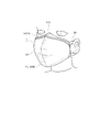
- FIG. 1 is a side view of the mask in a folded state according to the first embodiment.
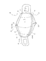
- FIG. 2 is a perspective view seen from the outside of the mask in the unfolded state according to the first embodiment.
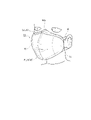
- FIG. 3 is a perspective view seen from the inside of the mask in the unfolded state according to the first embodiment.
- FIG. 4 is a diagram showing a wearing state of the mask according to the first embodiment.
- FIG. 5 is a schematic cross-sectional view of a mask.
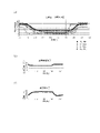
- FIG. 6 schematically shows the relationship between the length (A) of the covering portion of the mask in the extended state and the shortest length (B) of the upper and lower support portions, and the distance (L3) between the virtual line and the apex of the protrusion. It is a diagram.
- FIG. 6 schematically shows the relationship between the length (A) of the covering portion of the mask in the extended state and the shortest length (B) of the upper and lower support portions, and the distance (L3) between the virtual line and the apex of the
- FIG. 7 is a diagram showing antifogging evaluation.
- FIG. 8 is a side view of the mask in the folded state according to the sixth embodiment.
- FIG. 9 is a perspective view seen from the outside of the mask in the deployed state according to the sixth embodiment.
- FIG. 10 is a perspective view seen from the inside of the mask in the deployed state according to the sixth embodiment.
- FIG. 11 is a diagram showing a wearing state of the mask according to the sixth embodiment.
- FIG. 12 is a schematic cross-sectional view of the mask of the sixth embodiment.
- a mask according to one aspect has a covering portion that covers the wearer's mouth and is made of a film having a light transmittance of 80% or more.
- the humidity is changed from 30% to 70% 200 times at intervals of 3 seconds, and the humidity is changed from 70% to 30% after the fogging process.
- the compression anti-fogging index at humidity of 70% or higher of the cover is 15 or higher.
- the mask of this embodiment has a compression anti-fogging index of 15 or more in an environment with a humidity of 70% or more.
- the compression anti-fogging index is 15 or more, it is easy to ensure visibility on the back side through the cover portion. According to this aspect, it is possible to ensure the visibility of the facial expression under the usage environment of the mask.
- the compression antifogging index of the cover portion in the antifogging evaluation is 15 or more for 300 consecutive seconds or more. According to this aspect, the visibility of the covering portion can be ensured beyond 300 seconds, which is a temporary break of the conversation. Therefore, the visibility of facial expressions during conversation can be maintained.
- the minimum value of the compression antifogging index of the cover portion in the antifogging evaluation is 15 or more. According to this aspect, the visibility of the cover portion can always be ensured.
- the difference between the minimum value and the maximum value of the compression antifogging index of the cover portion in the antifogging evaluation is 25 or less. According to this aspect, since the difference between the maximum value and the minimum value of the compression anti-fogging index is small, there is little change in the visibility of the cover portion. Compared to the form in which the visibility of the covering part changes greatly, it is possible to continue to grasp the expression of the face without discomfort.
- the cover portion has a film layer composed of the film, and an anti-fogging layer disposed on the skin surface side of the film layer.
- the thickness of the antifogging layer is 5 ⁇ m or less, preferably 2 ⁇ m or less.
- the antifogging layer is arranged on the skin side of the film, and the antifogging effect can be exhibited on the surface where fogging occurs, and the effect can be easily obtained.
- the thickness of the anti-fogging layer is 5 ⁇ m or less, and the thickness of the anti-fogging layer is substantially close to 0 mm, so that the influence on visibility can be suppressed.
- the support portion has a support portion that supports the cover portion.
- the rigidity of the support portion is lower than the rigidity of the cover portion.
- the support portion is composed of a base fabric.
- the support portion is made of the base fabric and has higher breathability than the cover portion. Therefore, water vapor in the mask can be easily released to the outside through the support portion, and fogging of the cover portion can be reduced.
- the rigidity of the supporting portion is lower than that of the covering portion, the supporting portion tends to act as a cushioning area when the face moves. To prevent the cover from following the movement of the face too much, and to easily secure the visibility of the cover.
- the area of the region where the support part and the cover part overlap is 20% or less of the area of the cover part in the stretched state in which the cover part is stretched in the cross direction. According to this aspect, it is possible to reduce the area of covering the covering portion with the supporting portion, that is, the area that hinders visibility. Therefore, it is easier to ensure the visibility of the cover portion.
- the cheek rest portion has a cheek rest portion positioned on the skin surface side of the cover portion and in contact with the wearer's cheek.
- the stiffness of the cheek rest is lower than the stiffness of the cover.
- the said cheek rest part is comprised by the base fabric. According to this aspect, it is difficult for the covering portion to directly hit the cheek, and discomfort due to the direct contact of the covering portion against the cheek when worn can be suppressed.
- the stiffness of the cheek pad is lower than that of the cover, the cheek pad easily acts as a cushioning area. By acting as a cushioning area for the cheek pad, it is possible to prevent the cover from following the movement of the face too much.
- the cheek rest part is made of base fabric and has higher breathability than the cover part. Therefore, even if the cheek part directly touches the skin, it is possible to prevent the cheek part from coming into close contact with the skin due to water vapor or the like.
- it has a support part that supports the cover part, and a cheek support part that is positioned on the skin surface side of the cover part and contacts the wearer's cheek.
- the area of the region where at least one of the support portion and the cheek rest portion overlaps with the cover portion is 40% or less of the area of the cover portion in the stretched state in which the cover portion is stretched in the cross direction. According to this aspect, it is possible to reduce the area that covers the covering portion with at least one of the support portion and the cheek rest portion, that is, the area that hinders visibility. Therefore, it is easier to ensure the visibility of the cover portion.
- the mask may be a disposable mask intended for one-time use or a multiple-use mask.
- the same or similar reference numerals are given to the same or similar parts.
- the drawings are schematic and the ratio of each dimension may differ from the actual one. Therefore, specific dimensions and the like should be determined with reference to the following description.
- FIG. 1 to 5 are diagrams showing configuration examples of the mask 1 according to the first embodiment.
- FIG. 1 is a side view of a folded mask in which the mask is folded in half.
- 2 is a perspective view of the mask 1 in the unfolded state viewed from the outer surface side (non-skin surface side) Z2
- FIG. 3 is a perspective view of the unfolded mask 1 viewed from the inner surface side (skin surface side) Z1.
- FIG. 4 is a diagram showing how the mask according to the embodiment is worn.
- FIG. 5 is a schematic cross-sectional view of a mask.
- FIG. 5A is a schematic cross-sectional view taken along line AA shown in FIG.
- FIG. 5B is a cross-sectional view taken along line CC shown in FIG.
- the mask 1 has a covering portion 10 that covers at least the mouth of the wearer. It has an up-down direction X extending above and below the wearer's face and a cross direction Y perpendicular to the up-down direction X.
- the cross direction Y extends to the left and right sides of the wearer's face.
- the upper end edge and the lower end edge in the present invention are the edges located outside the vertical direction X, and the upper end portion and the lower end portion are constant in the vertical direction X including the edges located outside the vertical direction X.
- the outer edge in the present invention is an outer edge in the cross direction Y, and the outer portion is a portion occupying a certain range in the cross direction Y including the outer edge in the cross direction Y.
- the inner edge is an inner edge in the cross direction Y, and the inner portion is a portion occupying a certain range in the cross direction Y including the inner edge in the cross direction Y.
- the cover part 10 is made of a film with a light transmittance of 80% or more.
- the covering part 10 is configured to cover at least the mouth of the wearer, and may be configured to cover both the nose and the mouth.
- the cover part 10 may be folded with a body fold line FL10 extending along the vertical direction X at the center of the cross direction Y of the cover part 10 as a base point.
- the body fold line FL10 is a fold line for folding the cover portion 10 so that the inner surfaces of the cover portion 10 face each other. Therefore, the cover portion 10 is formed with a valley fold when viewed from the inner surface side Z1.
- the covering part 10 may be made of a single piece of material that is continuous in the cross direction Y. As shown in FIG.
- the cover portion is not composed of a single film, but has a left half sheet and a right half sheet, and the left half sheet and the right half sheet are formed at the center of the cover portion 10 in the cross direction Y. It may be joined. In the form in which the left half sheet and the right half sheet are joined, the joint is provided at the center of the cover part 10 in the cross direction Y, and the visibility of the cover part 10 is lowered. A joint portion of the cover portion 10 may constitute a low transparency portion, which will be described later. Also, in another embodiment, the mask 1 may be unfolded and unfolded prior to use. The cover 10 may be vacuum formed.
- the cover part 10 has a light transmittance of 80% or more and is substantially transparent. Incidentally, the light transmittance may be measured by a well-known method. For example, it can be measured in accordance with JIS K 7375 using a colorimetric color difference meter manufactured by Nippon Denshoku Industries Co., Ltd. or equivalent.
- the cover part 10 has an outer edge that forms the outer shape of the cover part 10 .
- the outer edges include a pair of outer edges 11 extending in the vertical direction X at the edges of the cover portion 10 in the cross direction Y, an upper edge 12 extending in the cross direction Y at the upper end of the cover portion 10, and a cross direction at the lower end of the cover portion 10. and a lower edge 13 extending in Y.
- the form extended in one direction is a concept including not only the structure parallel to one direction but the structure less than 45 degrees with respect to one direction.
- the mask 1 may have a support portion 20.
- the support portion 20 supports the cover portion 10 .
- the support portion 20 has upper and lower support portions.
- the vertical support part can stand up against the end part of the cover part 10 in the vertical direction X, and is arranged at least one of the upper side and the lower side with respect to the mouth when worn.
- the upper and lower support portions can stand up against the upper end portion of the cover portion 10, and can stand up against the upper support portion 22 arranged above the mouth when worn and the lower end portion of the cover portion 10, and can stand up against the lower end portion of the cover portion 10 when worn. and a lower support portion 23 arranged below the mouth.
- the vertical support part of the present embodiment has both the upper support part 22 and the lower support part 23
- the vertical support part may be either the upper support part 22 or the lower support part 23
- the structure in which the upper and lower support parts stand up may be a structure in which the upper and lower support parts stand up toward the skin surface side Z1 with respect to the cover part 10 when worn, and the upper and lower support parts stand up by unfolding the folded mask before use.
- the configuration may be such that the upper and lower support portions stand up from the beginning in the unfolded state (the state in which the covering portion of the mask is not folded) before use.
- the support part 20 may have a side support part 21 that covers at least part of the outer edge 11 of the cover part 10 .
- the side support portion 21 may cover the entire outer edge 11 of the cover portion 10 . According to this configuration, it is possible to prevent the outer edge 11 from digging into the face over the entire area of the outer edge 11 of the cover portion 10 .
- the side support portion 21 may also be continuous in the vertical direction X. In another embodiment, when the outer edge 11 of the cover portion 10 is separated in the vertical direction X, the side support portions 21 may also be separated in the vertical direction X and provided.
- the breathability of the support part 20 may be higher than the breathability of the cover part 10 .
- the cover part 10 is made of a film and has relatively low air permeability.
- the support portion 20 is made of, for example, nonwoven fabric, woven fabric, or urethane, and has relatively high air permeability. Therefore, even if the mouth is covered with the cover part 10 made of a film, breathability can be ensured via the support part 20 that supports the cover part, and breathing of the wearer can be ensured.
- the light transmittance of the cover portion 10 may be higher than the light transmittance of the support portion 20 .
- the mask 1 may have an ear hook portion 30 that is hooked on the wearer's ear.
- the ear hook portion 30 may continue to at least one of the support portion 20 and the cover portion 10 .
- the ear hooking portion 30 may be connected to both sides of the supporting portion 20 in the cross direction Y. As shown in FIG. Each ear hook 30 hooks behind the wearer's ear.
- the inner portion 33 of the ear hook portion 30 is connected to the outer portion of the support portion 20 .
- the inner portion 33 of the ear hook portion 30 may be continuous in the vertical direction X between the upper edge 31 of the inner portion 33 and the lower edge 32 of the inner portion 33 . are spaced apart from each other and may be connected to the support portion 20 respectively.
- the outer portion 34 of the ear hook 30 is configured to hook behind the wearer's ear. In a state in which both the pair of ear hooks 30 are put on the ears, the outer part of the cover part 10 and the support part 20 are pulled outward in the cross direction Y, and the cover part 10 covers the wearer's mouth. state is maintained.
- the ear hooking portion 30 may be formed by a sheet member made of nonwoven fabric or the like, and may be formed by a notch 35 formed in the sheet member, or may be formed by a cord-like elastic member.
- the upper support part 22, the lower support part 23 and the side support part 21 may be integrated with the same material. According to this configuration, the upper support portion 22, the lower support portion 23, and the side support portions 21 are easily interlocked, and the upper support portion 22, the lower support portion 23, and the side support portions 21 cooperate to fit the cover portion to the face. It becomes easier to let The support portion 20 and the cover portion 10 are joined to each other by the body joint portion 40 .
- the body joint portion 40 may be configured by at least one of sewing, ultrasonic waves, heat sealing, and adhesive.
- the main body joint portion 40 of the present embodiment is constructed by sewing, and seams are formed.
- the body joint portion 40 includes a side body joint portion 41 that joins the cover portion 10 and the side support portion 21, an upper body joint portion 42 that joins the upper support portion 22 and the cover portion 10, and the cover portion 10 and the lower support portion. and a lower body joint 43 that joins the lower body 23 .
- the side body joint portion 41 may join the ear hook portion 30 together with the cover portion 10 and the side support portion 21 . This makes it easier for the side support portion 21 and the cover portion 10 to interlock with the ear hook portion 30 .
- two upper body joint portions 42 may be provided at the upper end portion of the cover portion 10 at intervals in the vertical direction X.
- the upper support part 22 is folded on the non-skin surface side Z2 from the cover part 10 with the upper fold line 22F as a base point, and arranged in two layers. As will be described later, the upper support portion 22 is folded back toward the skin surface side Z1 with the upper edge of the cover portion 10 as a base point. A portion of the upper support portion 22 that is folded back from the upper edge of the cover portion 10 and extends beyond the upper edge of the cover portion 10 constitutes an upper folded portion 225 to be described later.
- the first upper body joint portion 42 joins the upper support portion 22 and the cover portion 10 in one layer, and serves as the folding base point of the upper fold line 22F.
- the second upper body joint portion 42 is arranged above the first upper body joint portion 42 and includes two layers of the upper support portion 22 (the portion where the upper support portion 22 is folded and arranged in two layers).
- the cover part 10 is joined.
- only one upper body joint portion 42 may be provided at the upper end portion of the cover portion 10, or only the first upper body joint portion of the present embodiment may be provided, or two upper body joint portions may be provided. Only the first upper body joint may be provided.
- two lower body joint portions 43 may be provided at the lower end portion of the cover portion 10 at intervals in the vertical direction X. As shown in FIG.
- the lower support part 23 is folded on the non-skin surface side Z2 from the cover part 10 with the lower fold line 23F as a base point, and arranged in two layers. Further, the lower support portion 23 is folded back toward the skin surface side Z1 with the lower edge 13 of the cover portion 10 as a base point, as will be described later. A portion of the lower support portion 23 that is folded back from the lower edge of the cover portion 10 and extends beyond the lower edge 13 of the cover portion 10 constitutes a lower folded portion 235 to be described later.
- the first lower body joint portion 43 joins the lower support portion 23 of one layer and the cover portion 10, and serves as a folding base point of the lower fold line 23F.
- the second lower body joint portion 43 is arranged below the first lower body joint portion 43, and includes two layers of the lower support portion 23 (the portion where the lower support portion 23 is folded and arranged in two layers) and the cover. joins the parts.
- only one lower body joint portion 43 may be provided at the lower end portion of the cover portion 10, and only the first lower body joint portion of the present embodiment may be provided, or the second lower body joint portion may be provided. Only the upper body joint may be provided.
- the second upper body joint portion 42 and the second lower body joint portion 43 may be provided along the outer edge of the cover portion 10 one round inside the outer edge, more specifically, 1 to 5 mm inside.
- the mask 1 of the present embodiment is configured so that the cover portion 10 and the upper and lower support portions can be easily formed in appropriate shapes.
- the upper and lower support portions and the cover portion 10 are in contact with each other at the upper and lower contact portions (see FIG. 5A) in the wearing state.
- the upper/lower contact portion 50 may be a portion where the upper/lower support portion and the cover portion 10 are in contact with each other in the wearing state.
- the upper and lower support portions stand up with respect to the cover portion with any edge of the upper and lower contact portions 50 as a base point. Therefore, the vertical contact portion constitutes a starting point of the vertical support portion.
- the vertical contact portion 50 has a first contact position P1, which is one outer edge of the vertical contact portion 50 in the cross direction Y, and a second contact position P1, which is the other outer edge of the vertical contact portion 50 in the cross direction Y. and a contact position P2.
- one outer edge in the cross direction Y is a right outer edge located on the right side when the mask 1 is viewed from the front
- the other outer edge in the cross direction Y is the left side when the mask is viewed from the front. is the left lateral edge located at
- the first contact position P1 is the upper first contact point where the right outer edge of the upper support portion 22 and the cover portion 10 are in contact.
- It includes a contact position P11 and a lower first contact position P12 where the right outer edge of the lower support portion 23 and the cover portion 10 are in contact, and the second contact position P2 is the left outer edge of the upper support portion 22. and a lower second contact position P22 where the cover portion 10 and the left outer edge of the lower support portion 23 contact.
- the shortest length (B) of the upper and lower support portions extending between the first contact position P1 and the second contact position P2 is the first contact position P1.
- the second contact position P2. 6 schematically shows the relationship between (A) and (B) of the mask 1 in the stretched state with reference to the cross section along line BB shown in FIG.
- the length (A) of the cover portion 10 is not the distance between the first contact position P1 and the second contact position P2 in the extended state, but the length of the cover portion 10 from the first contact position P1 to the second contact position P2. is the length of Specifically, the length (A) is, as shown in FIG. It is the total length of A2 and .
- (A) and (B) show the length of the cover portion 10 between the upper first contact position P11 and the upper second contact position P21, and the distance between the upper first contact position P11 and the upper second contact position P21. , and compare the length of the cover portion 10 between the lower first contact position P12 and the lower second contact position P22, and the distance between the lower first contact position P12 and the lower second contact position P22. . Further, the shortest length (B) of the vertical support portion is the shortest length of the vertical support portion extending between the first contact position P1 and the second contact position P2 in the extended state. It is replaced by the distance between P1 and the second contact position P2.
- the shortest length (B) of the upper support portion 22 ⁇ the length (A) of the cover portion 10 and the shortest length (B) of the lower support portion 23 ⁇ the length of the cover portion 10 are satisfied. At least one of (A) and (A) may be satisfied. Even if the upper and lower support portions and the cover portion 10 are in contact with each other such that the portion where the upper and lower support portions and the cover portion 10 contact each other has a predetermined width, the first contact position P1 and the second contact position P1 may be different.
- the shortest length of the upper and lower support portions extending between the contact positions P2 may be the distance in the cross direction Y between the outer edge of the first contact position P1 and the outer edge of the second contact position P2.
- the length of the cover portion extending between the first contact position P1 and the second contact position P2 is the length of the cover portion between the outer edge of the first contact position P1 and the outer edge of the second contact position P2. It may be the length of the cross direction Y along.
- the wearer when wearing the mask 1, the wearer forms the covering portion 10 in an elongated state in the cross direction Y so as to cover the mouth with the mask 1 and put the mask 1 on both ears. Wear 1. Therefore, the "stretched state" of the present invention is a state similar to a state in which the wearer pulls the mask 1 in the cross direction Y when wearing it. 10 from the outer edge of 10 to the inner side of the cross direction) is held by the upper and lower chucks of a tensile tester (such as Autograph AGS-X manufactured by Shimadzu Corporation), and the upper and lower chucks are separated. By widening the gap, the cover portion 10 is pulled at 2.0N.
- a tensile tester such as Autograph AGS-X manufactured by Shimadzu Corporation
- the upper and lower support portions maintain the distance between the ends of the cover portion 10 in the cross direction Y, and the cover portion 10 is configured to maintain a three-dimensional shape without becoming flat.
- the extended state if the shortest length (B) of the upper and lower support portions and the length (A) of the cover portion 10 are the same, the area between the first contact position P1 and the second contact position P2 is , in the extended state, both the upper and lower support parts and the cover part 10 have the same length and are planar.
- the shortest length (B) of the upper and lower support portions is shorter than the length (A) of the cover portion 10 . Therefore, in the extended state, when the upper and lower support portions are stretched flat in the region between the first contact position P1 and the second contact position P2, the cover portion 10 assumes a curved or bent three-dimensional shape. Further, the vertical support portion extends so as to connect the first contact position P1 and the second contact position P2 of the three-dimensional cover portion 10 and rises from the end portion of the cover portion 10 in the vertical direction X. As shown in FIG.
- the cover 10 can be three-dimensionally formed and the upper and lower support parts can be erected from the cover 10 by a general operation at the time of wearing, that is, the operation of extending the cover 10 .
- the wearer can form the mask 1 into an appropriate shape without being conscious of it, and can improve sealing performance while securing a space around the mouth.
- the contact position can be defined by the position at which the support portion 20 contacts the upper edge (or lower edge) of the cover portion 10 .
- the upper support part 22 has a configuration in which the standing member and the member connected to the cover part 10 are separate and connected to each other, the upper support part 22 is connected to the cover part 10.
- the contact position is the position where the member and the cover portion 10 are connected. That is, the member itself that stands on the wearer's side may not be directly connected to the cover portion 10, and if the member that stands on the wearer side is connected to the cover portion 10 via another member, other The position where the member and the cover portion 10 are connected becomes the contact position.
- the first contact position P1 and the second contact position P2 may be provided on the outer edge in the cross direction Y of the outer edge in the vertical direction X of the cover part 10 . More specifically, the upper first contact position P11 is provided on the right edge of the upper edge 12 of the cover portion 10, and the upper second contact position P21 is provided on the left edge of the upper edge 12 of the cover portion 10. you can The lower first contact position P12 may be provided at the right edge of the lower edge 13 of the cover portion 10, and the lower second contact position P22 may be provided at the left edge of the lower edge 13 of the cover portion 10. According to this configuration, the entire edge of the covering portion 10 in the vertical direction X can be covered by the vertical support portion extending between the first contact position P1 and the second contact position P2.
- the sealing performance of the mask 1 can be improved.
- the first abutment position P1 and the second abutment position P2 are located closer to the outer edge in the cross direction Y than the outer edge in the vertical direction X of the cover portion 10 (upper edge 12 and lower edge 13). It may be arranged inside the cross direction Y. That is, a partial region of the cover portion 10 in the cross direction Y may be formed into a curved shape by the upper and lower support portions.
- the ear hook portion 30 may be connected to at least one of the support portion 20 and the cover portion 10 at the connection position P3.
- the connecting position P3 may have a right connecting position P31 positioned on the right side in front view and a left connecting position P32 positioned on the left side in front view.
- FIG. 5B is a cross-sectional view taken along line CC shown in FIG.
- the ear hooking portion 30 is folded outward in the cross direction Y with the side crease 30F as a base point on the non-skin surface side Z2 of the covering portion 10 .
- a portion of the ear hook portion 30 that is not folded back around the side fold 30 ⁇ /b>F (a portion in contact with the cover portion 10 ) and the cover portion 10 are joined by a side body joining portion 41 .
- the portion that is folded back from the side fold line 30F and extends outward in the cross direction Y from the outer edge 11 of the cover portion 10 is arranged outside the cover portion when worn, and is placed on the wearer's cheeks and ears. be guessed.
- the connection position P3 in the present embodiment is the position of the side body joint portion 41 .
- the ear hook part of the present embodiment is connected to the support part 20 (upper and lower support parts and side support parts) at both the right connection position P31 and the left connection position P32.
- the cover portion 10 can be pulled through the support portion 20, and the cover portion 10 and the upper and lower support portions can be formed in a three-dimensional shape.
- the position of the connecting position P3 in the cross direction Y coincides with the first contact position P1 and the second contact position P2, or is positioned inside the cross direction Y of the first contact position P1 and the second contact position P2.
- the upper and lower supporting parts can be erected over the region extending between the first contact position P1 and the second contact position P2, and the cover part 10 can be formed in a three-dimensional shape.
- the ear hook part 30 may be connected to both the upper and lower support parts and the cover part 10 at the connecting position P3.
- the ear hooking part 30 By pulling the ear hooking part 30 in the cross direction Y, the upper and lower support parts and the cover part 10 can be pulled in the cross direction Y through the ear hook part 30, and the cover part 10 and the upper and lower support parts are extended.
- the cover part 10 and the upper and lower support parts can be formed in a three-dimensional shape.
- the ear hook part 30 may be connected to the upper and lower support parts, the cover part 10 and the cheek rest part 60 at the connecting position P3.
- the side support part 21 may be arranged on the non-skin surface side Z2 of the cover part 10 and connected to the ear hook part 30 .
- the side support part 21 and the covering part 10 can be pulled toward the face, and the outer edge 11 of the covering part 10 can be brought into close contact with the face.
- the side supporting portion 21 and the ear hooking portion 30 are made of the same material. You can The positional relationship between the ear hook portion 30 and the side support portion 21 is not limited, and the ear hook portion 30 may be arranged on the skin surface side Z1 of the side support portion 21, or may be arranged on the non-skin surface side Z2 of the side support portion 21. The ear hook portion 30 may be arranged in the . Alternatively, the outer edge 11 of the cover 10 may be supported only by the ear hooking portion 30 without the side support portion 21 covering the outer edge 11 of the cover 10 .
- a tuck portion may be formed to shorten the length in the cross direction Y of the upper and lower support portions.
- the tuck portion may have an upper tuck portion 221 provided on the upper support portion 22 and a lower tuck portion 231 provided on the lower support portion 23 .
- the upper tuck portion 221 is formed by joining the upper support portions 22 together.
- the lower support portions 23 are formed by joining the lower support portions 23 together.
- the tuck portion is formed by sewing.
- the tuck portion may be positioned on the non-skin surface side Z2 of the upper and lower support portions in the stretched state.
- the upper tuck portion 221 is arranged above the upper support portion 22, and the lower tuck portion 231 is arranged below the lower support portion 23.
- the wearer grasps the tuck portion located on the non-skin surface side Z2 with respect to the upper and lower support parts to adjust the position of the upper and lower support parts. and standing position can be adjusted.
- the tuck portion may extend in the height direction extending to the skin surface side Z1 and the non-skin surface side Z2 in the upright state of the upper and lower support portions.
- the tuck portion serves as a base point for supporting the upright state of the upper and lower support portions, making it easier to maintain the upright state of the upper and lower support portions.
- the tuck portion may be arranged in the center of the cross direction Y of the cover portion 10 . The wearer can easily grasp the position of the center of the mask 1 in the cross direction Y using the tuck portion as a mark, and can easily wear the mask 1 more appropriately.
- the length of the tuck portion in the cross direction Y may be longer toward the side away from the cover portion 10 (the skin surface side Z1 in the standing state).
- the length of the vertical support portion in the cross direction Y becomes shorter toward the side away from the edge of the cover portion 10 in the vertical direction X when the vertical support portion is in an upright state. Therefore, when the face is covered with the upper and lower support parts, the upper and lower end parts of the mask (the upper and lower support parts in an upright state) can be easily brought into close contact with the face, and the gap between the face and the mask can be reduced.
- the upper and lower support parts may have a nose fit member at a portion corresponding to the nose when worn.
- the upper and lower support parts may be joined to the non-skin surface side Z2 of the cover part 10 and folded back toward the outside of the cover part 10 .
- the upper and lower support portions may not be in contact with the non-skin surface of the cover portion 10, and may be joined to the non-skin surface side Z2 of the cover portion 10 via another member.
- the upper and lower support portions of the present embodiment are in contact with the non-skin surface of the cover portion and are joined by sewing. More specifically, the upper support portion 22 is joined to the non-skin surface side Z2 of the upper end portion of the cover portion 10 .
- the upper support portion 22 has an upper folded portion 225 folded back toward the non-skin surface side Z2 with the upper main body joint portion 42 located inside the outer edge of the cover portion 10 as a base point.
- the upper folded portion 225 is folded toward the outside of the cover portion 10 and extends beyond the outer edge of the cover portion 10 .
- the upper folded part 225 stands up on the skin surface side Z1 with respect to the cover part 10 when worn, and is arranged so as to cover the upper side of the mouth.
- the lower support portion 23 is joined to the non-skin surface side Z2 of the lower end portion of the cover portion 10 .
- the lower support portion 23 has a lower folded portion 235 folded back toward the non-skin surface side Z2 with the lower body joint portion 43 located inside the outer edge of the cover portion 10 as a base point.
- the lower folded portion 235 is folded toward the outside of the cover portion 10 and extends beyond the outer edge of the cover portion 10 .
- the lower folded part 235 stands up on the skin surface side Z1 with respect to the cover part 10 when worn, and is arranged so as to cover the lower side of the mouth.
- the outer edge of the cover portion 10 in the vertical direction X can be covered by the upper folded portion 225 and the lower folded portion 235 . Therefore, the airtightness at the ends of the mask in the vertical direction X can be improved.
- the length of the lower folded portion 235 in the vertical direction X may be longer than the length of the upper folded portion 225 in the vertical direction X (height direction when standing). According to this configuration, it is easy to cover the chin of the wearer with the mask, and it is possible to suppress the displacement of the mask caused by the movement of the mouth.
- the mask 1 of the present embodiment is configured to easily ensure the visibility of not only the mouth but also the area around the mouth.
- the ratio of the maximum length (L2) of the covering portion 10 in the vertical direction X to the maximum length (L1) of the covering portion 10 in the cross direction Y is 0.3 or more.
- the maximum length of the cover 10 in the cross direction Y is designed to cover the mouth and part of the cheeks
- the maximum length of the cover 10 in the vertical direction X is the mouth and cheeks. It is designed to be long enough to cover part of the nose.
- wearers who use sign language such as hearing-impaired wearers, childcare workers, and caregivers, who need to convey facial expressions to the other party, convey information not only by the mouth but also by the movement of the entire face. If the area of the cover part 10 is not sufficient, information may not be conveyed accurately and appropriately even if the cover part 10 is transparent. As a result of intensive research by the applicant, it was found that unless the height of the covering portion 10 in the vertical direction X is sufficient, the visibility of the entire cheek cannot be ensured, and it is difficult to convey information accurately and appropriately.
- the ratio of the maximum length (L2) of the cover portion 10 in the vertical direction X to the maximum length (L1) of the cover portion 10 in the cross direction Y is 0.3 or more. It is easy to sufficiently secure the length of the vertical direction X of 10, and the visibility of not only the mouth but also the periphery of the mouth such as cheeks can be secured by the cover part 10. ⁇ Therefore, it becomes easy to convey information accurately and appropriately. From the viewpoint of ensuring the visibility around the mouth by the cover part 10, the maximum dimension of the cover part 10 in the cross direction Y may be 180 mm or more and 220 mm or less, and the maximum dimension of the cover part 10 in the vertical direction X is 90 mm.
- the area of the covering portion 10 in which the vertical direction X is 90 mm or more may be 50% or more of the entire area of the covering portion 10 in the cross direction Y, and may be 90 mm or more.
- a protruding part 15 is provided at the center of the cover part 10 in the cross direction Y and protrudes toward the non-skin surface side Z2 from both edges of the cover part 10 in the cross direction Y. It is The protruding portion 15 only needs to protrude toward the non-skin surface side Z2 from the imaginary line EL (see FIG. 6) connecting both outer edges of the cover portion 10 in the cross direction. It may be formed over the cover portion 10 or may be formed in a part of the cover portion 10 in the cross direction Y. The center of the cover portion 10 in the cross direction Y may be the central area of the cross direction Y of the cover portion 10 divided into three equal parts.
- the projecting portion 15 may be arranged in at least part of the central region, and may be arranged beyond the central region in the cross direction. Moreover, the projecting portion 15 may straddle the center of the cross direction Y of the cover portion 10 or may not straddle the center of the cross direction Y of the cover portion 10 .
- the apex 15P of the projecting portion 15 is the point at which the projecting portion 15 protrudes most toward the non-skin surface side Z2, and may be arranged in the center of the cross direction Y of the cover portion 10, or may be displaced from the center of the
- the apex 15P of the projecting portion 15 of the present embodiment is provided on the body fold line FL10.
- the distance (L3) between the apex 15P of the projecting portion 15 and the imaginary line EL connecting both outer edges of the covering portion 10 in the cross direction Y is 15 mm or more.
- the imaginary line EL may be a line that connects the outermost points of the outer edges of the cover 10 in the cross direction.
- the distance between the virtual line EL and the vertex 15P of the projecting portion 15 is the distance between the inner surface of the cover portion at the vertex 15P of the projecting portion 15 and the virtual line EL connecting both outer edges of the inner surface of the cover portion 10 in the cross direction Y. , corresponds to the length of the space surrounded by the cover 10 in the depth direction.
- a wearer generally wears the mask 1 while forming the covering part 10 in an extended state extending in the cross direction Y in order to cover the mouth with the mask 1 and put the mask 1 on both ears when wearing it. .
- the distance between the apex of the projecting portion and the virtual line EL connecting both outer edges of the covering portion 10 in the cross direction Y is 15 mm or more. It makes it easier to convey facial expressions without hindering movement.
- the area of the region where the upper support part 22 and the cover part 10 overlap in the stretched state may be 20% or less of the area of the cover part 10 . According to this configuration, it is possible to reduce the area covered by the upper support portion 22 on the cover portion 10, that is, the area that hinders visibility. Therefore, it is easier to ensure the visibility of the cover portion 10 .
- the area where the upper support part 22 and the cover part 10 overlap is the area where the upper support part 22 and the cover part 10 overlap when the mask 1 in the stretched state is viewed from the front. In the overlapping region, the upper support part 22 and the cover part 10 may be joined, the upper support part 22 and the cover part 10 may be in contact without being joined, or the upper support part 22 and the cover part may be in contact with each other.
- the cover portion 10 may be spaced apart. Further, the area of the region of the upper and lower contact portions that overlaps the upper support portion 22 and the cover portion 10 may be 20% or less, more preferably 10% or less, of the area of the cover portion 10 . According to this configuration, it is possible to secure an area where the upper support portion 22 and the cover portion 10 are not in contact with each other, thereby further improving visibility through the cover portion 10 .
- the upper support part 22 is joined to the non-skin surface side Z2 of the cover part 10 and is folded back toward the outside of the cover part 10 . Since the upper support part 22 is folded back and stands on the skin surface side Z1 when worn, it is easy to ensure the standability with respect to the cover part 10 . By erecting the upper supporting portion 22 with respect to the covering portion 10, the area covered by the covering portion 10 with the upper supporting portion 22, that is, the area that obstructs visibility can be reduced. Therefore, it is easier to ensure the visibility of the cover portion 10 .
- the rigidity of the upper support portion 22 may be lower than that of the cover portion 10 .
- the upper support part 22 Since the rigidity of the upper support part 22 is lower than that of the cover part 10, the upper support part 22 tends to act as a cushioning area when the face moves. Therefore, the cover 10 is prevented from following the movement of the face too much, and the visibility of the cover 10 is easily ensured.
- the standing height of the upper support part 22 in the extended state may be 25 mm or more.
- the standing height of the upper support portion 22 is the height extending vertically from the cover portion 10 in the extended state. It is sufficient that the highest standing height of the upper support portion 22 is 25 mm or more. Since the upright height of the upper support part 22 is 25 mm or more, the top of the nose can be easily covered with the upper support part 22 . A distance between the cover part 10 and the face is ensured, and the cover part 10 hardly hits the face directly when the face moves. Therefore, it is possible to prevent the cover from excessively following the movement of the face, and it is easy to ensure the visibility of the cover 10 . More preferably, the standing height of the upper support portion 22 in the extended state may be 35 mm or more.
- the area of the region where the lower support part 23 and the cover part 10 overlap in the stretched state may be 20% or less of the area of the cover part 10 .
- the area covered by the cover portion 10 with the lower support portion 23, that is, the area that hinders visibility can be reduced. Therefore, it is easier to ensure the visibility of the cover portion 10 .
- 80% or more of the cover part does not overlap the lower support part 23, and visibility can be secured over a wide range of the cover part 10. ⁇
- the region where the lower support portion 23 and the cover portion 10 overlap is the region where the lower support portion 23 and the cover portion 10 overlap when viewed from the front of the stretched mask.
- the lower support portion 23 and the cover portion 10 may be joined, the lower support portion 23 and the cover portion 10 may be in contact without being joined, or the lower support portion 23 and the cover portion may be in contact with each other. 10 may be spaced apart. Further, the area of the region of the upper and lower contact portions that overlaps the lower support portion 23 and the cover portion 10 may be 20% or less, more preferably 10% or less, of the area of the cover portion 10 . According to this configuration, it is possible to secure an area where the lower support portion 23 and the cover portion 10 are not in contact with each other, thereby further improving the visibility through the cover portion 10 .
- the total area of the overlapping area of the upper support part 22 and the cover part 10 and the overlapping area of the lower support part 23 and the cover part 10 may be 30% or less of the area of the entire cover part, More preferably, it may be 20% or less.
- the area where the support portions (upper support portion 22, side support portion 21) and the cover portion 10 overlap may be 30% or less, more preferably 20% or less, of the entire area of the cover portion. . Since there is little area where the entire support portion overlaps the cover portion, visibility of the cover portion can be more easily ensured.
- the lower support part 23 is joined to the non-skin surface side Z2 of the cover part 10 and folded back toward the outside of the cover part. Since the lower support portion is folded back and stands on the skin surface side Z1 when worn, it is easy to secure the standing property with respect to the cover portion 10 . By erecting the lower support part 23 with respect to the cover part 10, the area covered by the lower support part 23 on the cover part 10, that is, the area that hinders visibility can be reduced. Therefore, it is easier to ensure the visibility of the cover portion 10 .
- the rigidity of the upper support portion 22 may be lower than that of the cover portion 10 .
- the lower support part 23 Since the rigidity of the lower support part 23 is lower than that of the cover part 10, the lower support part 23 tends to act as a cushioning area when the face moves. Therefore, the cover 10 is prevented from following the movement of the face too much, and the visibility of the cover 10 is easily ensured.
- the standing height of the lower support part 23 in the extended state may be 25 mm or more.
- the standing height of the lower support portion 23 is the height extending vertically from the cover portion 10 in the extended state. It is sufficient that the highest standing height of the lower support portion 23 is 25 mm or more. Since the standing height of the lower support part 23 is 25 mm or more, the lower support part 23 can easily cover the chin. In addition, since the distance between the covering part 10 and the face can be secured, the covering part 10 does not come into direct contact with the face when the face moves. Therefore, the cover 10 is prevented from following the movement of the face too much, and the visibility of the cover 10 is easily ensured. More preferably, the standing height of the upper support in the extended state may be 35 mm or more. The standing height of the lower support 23 may be higher than the standing height of the upper support 22 .
- the color of the support portion 20 may be a color that easily blends in with the skin.
- the colors of the support portion 20 are beige (#FFB74C), brown (#994C00), orange (#FFB74C), ocher (#c39143), ocher (#CC7722), orange (#f39800), Can be cream (#FFEDB3), bisque (#FFE4C4), honey (#e7bb5e), caramel (#90692c), walnut (#a86f4c).
- a color having a color difference ⁇ E of 20.0 or less with respect to the color concerned may be regarded as the same color as the color concerned. More preferably, a color with a color difference ⁇ E of 12.0 or less with respect to the color may be included.
- the difference in L* value between two points to be measured is ⁇ L*
- the difference in a* is ⁇ a*
- the difference in b* value is ⁇ b*
- color difference ⁇ E [( ⁇ L*) 2 +( ⁇ a*) 2 +( ⁇ b*) 2 ] 1/2
- the color of the support portion 20 may be, for example, any of the colors (including No. 2 and No. 6) having hue numbers between No. 2 and No. 6 on the Ostwald color wheel. Since the color of the support part 20 blends well with the skin, the support part 20 becomes less conspicuous, and the presence of the support part 20 prevents the facial expression from becoming less conspicuous. Therefore, the visibility of the facial expression is enhanced, and the facial expression can be easily conveyed.
- the rigidity of the covering portion 10 may be higher than that of the supporting portion 20. Since the cover part 10 has a relatively high rigidity and is easy to maintain its shape, the cover part 10 is prevented from coming into close contact with the mouth unintentionally due to breathing, and the wearer can easily breathe. Further, by covering the entire outer edge 11 of the cover 10 with the support 20 having relatively low rigidity, the outer edge 11 of the cover 10 does not hit the face directly, but hits the face via the support 20 . Therefore, it is possible to suppress discomfort due to the outer edge 11 of the cover portion 10 digging into the face. In addition, even when the outer edge 11 of the cover part 10 is lifted from the face, the support part 20 can be flexibly deformed, so that the support part 20 can ensure close contact with the face.
- the displacement of the mask 1 due to the outer edge of the cover portion 10 coming into contact with the hand or the like can be suppressed.
- a wearer who uses sign language such as a hearing-impaired person, performs an action of placing a hand around the face, such as placing a hand on the cheek in sign language.
- the adhesion of the outer edge 11 of the cover part 10 is high, it is possible to suppress troubles such as hindrance of the sign language action and erroneous recognition that the action to correct the positional deviation of the mask 1 is the sign language action.
- the thickness of the cover part 10 may be 100 ⁇ m or more and 600 ⁇ m or less. Since the cover part 10 has a thickness of 600 ⁇ m or less and is relatively thin, it does not give a sense of discomfort when the face is covered, and it is possible to prevent the cover part 10 from floating up and hitting a hand or the like. In addition, when the thickness of the cover portion 10 is less than 100 ⁇ m (for example, 80 ⁇ m), the rigidity of the cover portion 10 is too low, and the cover portion 10 may come into close contact with the mouth. However, since the thickness of the cover part 10 is 100 ⁇ m or more, the cover part 10 can be given a certain rigidity, and the problem that the film sticks to the mouth and makes it difficult to breathe can be suppressed.
- the thickness of the covering portion 10 may be 180 ⁇ m or more.
- the thickness of the cover part 10 is 180 ⁇ m or more, the shape of the film is easily stabilized, and the cover part 10 can be easily arranged while maintaining a constant distance from the mouth.
- a high-rigidity portion having higher rigidity than the surroundings may be provided extending in the vertical direction X at the center of the cover portion 10 in the cross direction Y.
- the shape of the central portion of the cover portion 10 in the cross direction Y can be maintained by the high-rigidity portion, and deformation of the cover portion 10 and close contact with the mouth can be suppressed.
- the high-rigidity portion of the present embodiment is constituted by the body fold line FL10. Further, in another embodiment, the high-rigidity portion may be configured by a joint portion in which the films forming the cover portion 10 are joined together.
- the joint part is not provided at the center of the cover part 10 in the cross direction Y.
- the high-rigidity portion may constitute a low-transparency portion, which will be described later.
- the support part 20 and the ear hook part 30 may be made of the same material. That is, the supporting part 20 and the ear hooking part 30 may be continuously formed of the same material instead of joining separate materials.
- the ear hook portion 30 pulls the entire outer edge 11 of the cover portion 10 outward in the cross direction Y via the support portion 20 when worn. At this time, since the support part 20 and the ear hook part 30 are integrated, the support part 20 and the ear hook part 30 can cooperate to pull the outer edge 11 of the cover part 10 and press it toward the face. Therefore, lifting of the outer edge 11 of the cover portion 10 can be suppressed.
- the support portion 20 may cover the entire area of the outer edge 11 of the cover portion 10 in the vertical direction X.
- the ear hook portion 30 can pull the upper edge and the lower edge of the outer edge 11 of the cover portion 10 in the cross direction Y via the support portion 20 .
- the ear hooking portion 30 and the support portion 20 are formed by separate members, and the ear hooking portion 30 is connected to the upper edge and the lower edge of the support portion 20 respectively, the ear hooking portion 30 is connected to the upper edge of the support portion 20
- the edge and the lower edge are pulled in the cross direction Y, and the upper edge and the lower edge of the support portion 20 are pulled in a direction toward each other (inward in the vertical direction X).
- the upper edge and the lower edge of the outer edge 11 of the cover part 10 are deformed so as to approach each other, and the outer edge 11 of the cover part 10 may be curved and lifted. More specifically, when the upper edge and the lower edge of the outer edge 11 of the cover part 10 are deformed so as to approach each other, the center of the outer edge 11 of the cover part 10 in the vertical direction X is curved so as to be lifted, and the outer side of the cover part 10 is curved. The edge 11 is easily lifted from the face. In particular, the covering portion 10 made of a film is likely to be curved, and the outer edge 11 is easily maintained in a raised state with respect to the cheek.
- the supporting portion 20 and the ear hooking portion 30 are made of the same material, the entire outer edge 11 of the cover portion 10 is pressed toward the face, and the outer edge 11 can be prevented from being curved and lifted.
- the support portion 20 and the ear hook portion 30 may be made of separate materials and joined together in a row.
- the support part 20 may be made of a stretchable base fabric.
- the base fabric is a non-woven fabric or a woven fabric. Since the supporting portion 20 is made of the base fabric, it is possible to improve the touch feeling and to secure the breathability. In addition, since the support part 20 has elasticity, it is possible to enhance the adhesion of the support part to the face and the adhesion of the outer edge of the cover part to the face. Since the supporting portion 20 is made of the base fabric, it is possible to improve the touch feeling and to secure the breathability.
- the supporting portion 20 may be configured to be expandable and contractable at least in the cross direction Y, and more preferably, be configured to be expandable and contractable in the cross direction Y and the vertical direction X.
- the base fabric can be exemplified by polyester, polyurethane, foam such as urethane foam, non-woven fabric, and paper.
- the mask of the second embodiment covers the vertical direction X extending vertically when worn, the cross direction Y orthogonal to the vertical direction X, and the wearer's mouth, and is composed of a film having a light transmittance of 80% or more. It has a cover part 10 .
- the cover part 10 is provided with a low transparency part 80 extending in the vertical direction and having a lower transparency than the surroundings.
- the low transparency portion 80 makes it easy for the wearer to grasp the position of the cover portion 10 . Therefore, it is easy to mount the mask 1 at an appropriate position.
- the mask of the second embodiment may not have the upper and lower support parts, and the relationship between the length of the upper and lower support parts and the length of the cover part may not satisfy B>A.
- the ratio of the maximum length (L2) in the vertical direction of the cover portion to the maximum length (L1) in the cross direction of the portion may not be satisfied, and the distance (L3) may not be 15 mm or more.
- the low transparent portion 80 may extend in the vertical direction X.
- the configuration in which the low transparency portion 80 extends in the vertical direction X is a concept that includes not only a configuration parallel to the vertical direction X, but also a configuration inclined with respect to the vertical direction X at an angle of 45 degrees or less. According to this aspect, the user can easily grasp the orientation of the mask 1 in the vertical direction, and can wear the mask 1 appropriately.
- the covering portion 10 is suppressed from being sagging in the vertical direction X, the covering portion 10 is maintained flat, and the area of the covering portion 10 is ensured. becomes easier.
- the low transparency portion 80 may extend in the cross direction Y.
- the configuration in which the low transparent portion 80 extends in the cross direction Y is a concept that includes not only a configuration parallel to the cross direction Y, but also a configuration inclined with respect to the cross direction Y at an angle of less than 45 degrees. According to this aspect, the user can easily grasp the orientation of the mask 1 in the cross direction Y, and can wear the mask 1 appropriately.
- the covering portion 10 is suppressed from being sagging in the cross direction Y, the covering portion 10 is maintained flat, and the area of the covering portion 10 is ensured. becomes easier.
- the low transparent portion 80 may be provided in the center of the cover portion 10 in the cross direction Y.
- the low transparency portion 80 makes it easy for the wearer to grasp the central position of the cover portion 10 in the cross direction Y, and the low transparency portion 80 can be used as a mark to facilitate alignment with the face.
- the number of the low transparent portions 80 may be one as in the present embodiment, or a plurality of portions may be provided at intervals in the cross direction Y.
- the low transparency portion 80 may be provided over the entire area of the cover portion 10 in the vertical direction X, or may be provided in a partial area of the cover portion 10 in the vertical direction X.
- the low-transparency portion 80 may be formed by the body fold line FL10 formed in the cover portion 10, or may be a joint portion in which films forming the cover portion 10 are joined together, or may constitute the cover portion. It may be a portion in which another member is joined to the sheet to be connected.
- the joint between the cover portions may be formed by welding or may be formed by an adhesive.
- the joining portion between the cover portions may be formed by joining two separate sheets, or may be formed by folding one sheet and joining the folded sheets.
- the low-transparency portion 80 may be configured to have a lower light transmittance than the region adjacent to the low-transparency portion.
- the light transmittance can be measured according to JIS K 7375 using, for example, a colorimetric color difference meter manufactured by Nippon Denshoku Industries Co., Ltd. or equivalent.
- the length of the low transparent portion in the cross direction Y may be 10% or less, more preferably 5% or less of the entire cross direction Y of the cover portion 10 . Since the area occupied by the low-transparency portion in the cover portion is small, it is possible to suppress deterioration in the visibility of the cover portion due to the existence of the low-transparency portion.
- the rigidity of the low transparency portion 80 may be higher than that of the surrounding area of the cover portion 10 .
- the shape of the cover part 10 is supported by the low transparent part 80, the length of the cover part 10 in the cross direction Y can be secured, and deformation of the cover part and close contact with the mouth can be suppressed.
- the low transparency portion 80 is formed in the center of the cover portion 10 in the cross direction Y, the size of the center of the cover portion 10 in the cross direction Y can be ensured, making it easier to form a space for the mouth.
- the mask according to the third embodiment covers the vertical direction X extending vertically when worn, the cross direction Y orthogonal to the vertical direction X, and the wearer's mouth, and is composed of a film having a light transmittance of 80% or more. and a cover portion 10 .
- a projecting portion 15 is provided at the center of the cover portion in the cross direction so as to protrude toward the non-skin surface side from both edges of the cover portion in the cross direction.
- the cover part 10 is provided with a low transparency part 80 extending in the vertical direction and having a lower transparency than the surroundings.
- the low transparency portion 80 makes it easy for the wearer to grasp the position of the cover portion 10 . Therefore, it is easy to mount the mask 1 at an appropriate position.
- the protruding part is provided to swell to the non-skin surface side in the stretched state, the covering part does not come into too close contact with the mouth and does not interfere with the movement of the face, making it easy to convey the expression of the face.
- the mask of the third embodiment may not have the upper and lower support parts, and the relationship between the length of the upper and lower support parts and the length of the cover part may not satisfy B>A.
- the ratio of the maximum length (L2) in the vertical direction of the cover portion to the maximum length (L1) in the cross direction of the portion may not be satisfied.
- the maximum length (L2) of the covering portion in the vertical direction X is 90 mm or more and 120 mm or less.
- a projecting part is provided at the center of the cover part in the cross direction so as to protrude to the non-skin surface side from both edges of the cover part in the cross direction.
- the distance (L3) between the apex of the projecting portion and the imaginary line connecting both lateral edges of the covering portion in the crossing direction is 15 mm or more.
- the mask of the fourth embodiment may not have the low transparent portion and may not have the upper and lower support portions. >A, and the ratio of the maximum vertical length (L2) of the cover to the maximum cross-direction length (L1) of the cover need not be satisfied.
- the mask according to the fifth embodiment is configured so as to improve the visibility of facial expressions in the usage environment of the mask.
- the covering portion 10 of the mask of the fifth embodiment is configured so that the compression anti-fogging index at a humidity of 70% or higher in the anti-fogging evaluation is 15 or higher.
- the anti-fogging evaluation is an evaluation of the appearance when the cloudy process and the sunny process are performed in an environment where the ambient temperature of the measurement room is 25 degrees, and the evaluation method and evaluation results will be described in detail. do.
- FIG. 7(a) is a diagram showing the results of antifogging evaluation.
- FIG. 7(b) is a diagram showing changes in fixed surface temperature.
- FIG. 7(c) is a diagram showing changes in humidity in the measurement room.
- AFA-2 Karlinsky Interface Science Co., Ltd.
- the ambient temperature in the measurement chamber was set at 25°C.
- a series of measurements in the cloudy process and the sunny process were measured, and the end time of one measurement was 870 seconds (about 15 minutes).
- the anti-fogging evaluation was performed by changing the humidity from 30% to 70% 200 times at 3-second intervals, and after the fogging process, moving from 70% to 30% humidity at 90% humidity at 3-second intervals. and a clearing process that transitions through changes in times.
- Example 1 Four samples, ie, the sample of Example 1 and the samples of Comparative Examples 1 to 3, were used for antifogging evaluation according to Examples.
- a landscape image was placed on the back side of the cover, and how the background image was seen through the cover was evaluated at times X and Y shown in FIG. 7(a).
- Evaluation is based on good visual acuity (1.0 or more) at a distance of about 30 to 50 cm in a brightly lit room (approximate color temperature: 4600 to 5400 K (Kelvin)) (approximate color temperature: 4600 to 5400 K (Kelvin)). ) in both eyes, and the results of the majority were taken as the measurement results.
- “ ⁇ ” will be displayed. was evaluated with “x”.
- “visible” in the present invention means a room (reference: 500 to 750 lx (lux)) brightly illuminated with neutral white (color temperature guideline 4600 to 5400 K (Kelvin), or D65 light source (6504K)). It means that a subject with good visual acuity (1.0 or better) in both eyes can see an object at a distance of about 30-50 cm. The results are shown in Table 1 below. From the evaluation results, if the compression anti-fogging index is less than 15, it is difficult to ensure visibility through the cover, and if the compression anti-fogging index is 15 or more, visibility through the cover can be ensured. all right.
- the cover part 10 is made of a film and has low breathability compared to base fabric such as nonwoven fabric. Therefore, a mask including a transparent film tends to have high humidity inside the mask due to the water vapor produced by respiration. As a result of intensive investigation by the applicant, generally, the humidity inside the mask often reaches 70% or more when the mask is worn continuously for 5 seconds or more.
- the mask of this embodiment has a compression anti-fogging index of 15 or more in an environment with a humidity of 70% or more. As a result of intensive research by the applicant, it was found that when the compression anti-fogging index is 15 or more, it is easy to ensure visibility on the back side through the cover portion.
- the compression anti-fogging index of the cover for anti-fogging evaluation is 15 or more for 300 consecutive seconds or more.
- the wearer's conversation is often interrupted at about 300 seconds. becomes possible.
- the visibility of the covering portion can be ensured beyond 300 seconds, which is a temporary break of the conversation. Therefore, it is possible to continue to ensure the visibility of facial expressions during conversation.
- the minimum value of the compression anti-fogging index of the cover for anti-fogging evaluation is 15 or more. That is, as shown in FIG. 7, the compression antifogging index of the covering portion (Sample 1) of the mask of the present embodiment was 15 or more. According to this configuration, good visibility can be continuously maintained even in an environment where the humidity and temperature change.
- the difference between the minimum value and the maximum value of the compression antifogging index of the cover for antifogging evaluation is 25 or less.
- the compression anti-fogging index of the covering portion (Sample 1) of the mask of the present embodiment is 40 or less and 15 or more in all steps of anti-fogging evaluation (continuously from 0 seconds to 870 seconds), The difference is 25 or less. If the difference between the maximum value and the minimum value of the compression anti-fogging index is large, the visibility through the cover changes. Therefore, the appearance of the mouth of the wearer may be difficult to see or easy to see, and depending on the conversation partner, it may be difficult to see the visibility of the mouth due to the change in visibility, or there is a risk of discomfort. there were. However, since the difference between the maximum value and the minimum value of the compression anti-fogging index is small, there is little change in the visibility of the cover. Favorable visibility can be more easily ensured compared to the form in which the visibility of the cover portion changes greatly.
- the cover part 10 may have a film layer composed of a film and an anti-fogging layer arranged on the skin surface side of the film layer.
- the thickness of the antifogging layer may be 5 ⁇ m or less, preferably 2 ⁇ m or less.
- the anti-fogging layer is arranged on the skin side of the film, and the anti-fogging effect can be exhibited on the surface where fogging occurs, and the effect can be easily obtained.
- the thickness of the anti-fogging layer is 5 ⁇ m or less, and the thickness of the anti-fogging layer is substantially close to 0 mm, so that the influence on visibility can be suppressed.
- the anti-fogging layer may be arranged on the skin side Z1 relative to the film layer.
- the anti-fogging layer By arranging the anti-fogging layer on the inner surface side of the mask (the side where fogging tends to occur), the anti-fogging effect is more likely to be exhibited.
- the material of the film layer is not particularly limited, and known films can be used. Examples include PMMA (acrylic), PET (polyethylene terephthalate), PP (polypropylene), and PC (polycarbonate).
- the thickness of the film layer is not limited, and the thickness of the covering portion including the film layer and the antifogging layer may be 100 ⁇ m or more and 600 ⁇ m or less.
- the structure of the anti-fogging layer is not particularly limited, and it may be coated with a well-known anti-fogging agent (for example, a fatty acid-based nonionic surfactant), or may be coated with nanoparticles.
- the rigidity of the support part 20 may be lower than that of the cover part 10, and the support part 20 may be made of a base fabric.
- the support part 20 is made of a base fabric and has higher air permeability than the cover part 10 . Therefore, water vapor in the mask 1 can be easily released to the outside through the support portion 20, and fogging of the cover portion 10 can be reduced.
- the support portion 20 since the rigidity of the support portion 20 is lower than that of the cover portion 10, the support portion 20 tends to act as a cushioning area when the face moves. The cover part 10 is prevented from following the movement of the face too much, and the visibility of the cover part 10 is easily ensured.
- the area of the region where the support part 20 and the cover part 10 overlap may be 20% or less of the area of the cover part 10 .
- the total area of the upper supporting portion 22, the lower supporting portion 23 and the side supporting portions 21 constituting the supporting portion and the cover portion 10 overlap may be 20% or less of the area of the cover portion 10.
- FIG. it is possible to reduce the area of covering the covering portion with the supporting portion, that is, the area that hinders visibility. Therefore, it is easier to ensure the visibility of the cover portion 10 .
- the mask of the fifth embodiment may not have the low transparent portion and may not have the upper and lower support portions. >A, and the ratio of the maximum vertical length (L2) of the cover to the maximum cross-direction length (L1) of the cover need not be satisfied. Also, the distance (L3) between the virtual line and the vertex of the projecting portion does not have to be 15 mm or more. Moreover, the mask of the fifth embodiment may not have the support portion, and the ear hook portion 30 may be directly connected to the cover portion 10 .
- FIG. 8 is a side view of the mask in a folded state in which the mask 1X is folded in half.
- 9 is a perspective view of the mask 1X in the unfolded state as seen from the outer surface side (non-skin surface side) Z2
- FIG. 10 is a perspective view of the mask 1X in the unfolded state as seen from the inner surface side (skin surface side) Z1.
- FIG. 11 is a diagram showing how the mask 1X according to the embodiment is worn.
- FIG. 12 is a schematic cross-sectional view of the mask 1X.
- FIG. 12A is a schematic cross-sectional view along line EE shown in FIG. 10
- FIG. 12B is a schematic cross-sectional view along line FF.
- the mask 1X has cheek pads 60.
- the cheek rest part 60 is positioned closer to the skin surface side Z1 than the cover part 10, and is arranged so as to be in contact with the wearer's cheek. Since the mask 1X has the cheek rest portion 60, the covering portion 10 is unlikely to come into direct contact with the cheek, and discomfort due to the covering portion 10 coming into direct contact with the cheek when worn can be suppressed.
- the stiffness of the cheek rest portion 60 may be lower than the stiffness of the covering portion 10 . Since the stiffness of the cheek pad 60 is lower than the stiffness of the cover 10, the cheek pad 60 easily acts as a cushioning area. By acting as a cushioning region for the cheek pad 60, it is possible to prevent the cover 10 from following the movement of the face too much.
- the cheek rest part 60 is made of a base fabric and has higher breathability than the cover part 10 . Therefore, even if the cheek part 60 directly touches the skin, it is possible to prevent the cheek part 60 from coming into close contact with the skin due to water vapor or the like.
- the cheek pad portion 60 may be arranged on the skin surface side Z1 relative to the cover portion 10, may be arranged on the non-skin surface side Z2 relative to the ear hook portion 30, or may be located on the skin surface rather than the ear hook portion 30. It may be arranged on the surface side Z1.
- the cheek rest portion 60 of the present embodiment is arranged on the skin surface side Z1 of the cover portion 10 and on the skin surface side Z1 of the ear hook portion 30 .
- the covering part 10 is positioned closer to the skin surface side Z ⁇ b>1 than the ear hooking part 30 and is sandwiched between the ear hooking part 30 and the cheek pad part 60 .
- the cheek pad portion 60 , the ear hook portion 30 , the cover portion 10 and the side support portion 21 may be joined together by a side body joint portion 41 .
- the position of the cheek rest 60 in the cross direction Y is not particularly limited.
- the cheek rest portion 60 may overlap the outer edge 11 of the covering portion 10 in the cross direction Y.
- the outer edge 11 of the cover part 10 tends to serve as a fulcrum at which the center of the cover part 10 in the intersecting direction stands on the non-skin surface side, and easily comes into close contact with the cheek.
- the cheek support part 60 By arranging the cheek support part 60 so as to overlap the outer edge 11 of the cover part 10, the contact with the cheek can be softened.
- the cheek rest portion 60 may be arranged only inside the outer edge 11 of the cover portion 10 in the cross direction Y without overlapping the outer edge 11 of the cover portion 10 .
- the inner edge in the transverse direction Y of the cheek rest portion 60 may be located in a region extending inwardly in the transverse direction Y from the outer edge 11 of the cover portion 10 to 40 mm.
- the cheek pad 60 has a lower light transmittance than the cover 10, and if the area of the cheek pad 60 is too large, the visibility of the cover 10 is reduced. Therefore, the inner edge of the cheek rest 60 in the cross direction Y is preferably located in a region extending inward in the cross direction Y from the outer edge 11 of the cover part 10 to 40 mm, and more preferably, the cover part 10 from the outer edge 11 toward the inside in the cross direction Y up to 30 mm.
- the cheek rest portion 60 may be continuous between the outer edge 11 of the cover portion 10 and 40 mm inward in the cross direction Y from the outer edge 11 of the cover portion 10 .
- the cheek pads 60 may be arranged on the left and right outer sides of the cover 10, respectively.
- the pair of cheek rests 60 may be spaced apart in the cross direction Y.
- the cheek rest portion 60 is not arranged in a region extending from the main body fold FL10 outward in the cross direction Y to 30 mm, more preferably, in a region extending from the main body fold FL10 to the outside in the cross direction Y up to 40 mm. is preferably not located in the According to the said structure, it is easy to ensure the visibility of the cover part 10.
- the length of the cheek rest portion 60 in the cross direction Y may be 50% or less of the length between the body fold FL10 of the cover portion 10 and the outer edge 11 of the cover portion 10, preferably 40%.
- the area of the region where the cheek support portion 60 overlaps the cover portion 10 may be 40% or less, preferably 30%, of the area of the cover portion 10. Below, more preferably, it may be 20% or less. According to this aspect, it is possible to reduce the area of the covering portion 10 covered by the cheek rest portion 60, that is, the area that hinders visibility.
- the area of the region where at least one of the support portion 20 and the cheek rest portion 60 overlaps with the cover portion 10 is 50% or less of the area of the cover portion 10. preferably 40% or less, more preferably 30% or less.
- the area covered by at least one of the support part 20 and the cheek rest part 60 includes the area covered by the support part 20 only, the area covered by the cheek rest part 60 only, and the area covered by the support part 20 and the cheek. It is an area obtained by combining the areas covered by the cover portion 10 with the contact portions 60 overlapping each other.
- the cheek rest 60 is configured to stand on the non-skin side Z2 together with the cover 10 when the center of the cover 10 in the cross direction Y stands on the non-skin side Z2. Therefore, the cheek rest part 60 is joined to the covering part 10 inside the outer edge of the cheek rest part 60 in the cross direction Y.
- the upper and lower support portions stand on the skin surface side Z1 with respect to the cover portion 10 and the cheek rest portion 60 . As shown in FIG.
- the outer periphery (including the outer edge of the cheek rest 60 and the outer side extending in the vertical direction X) other than the inner side 64 extending in the vertical direction X from the inner edge of the cheek rest 60
- the upper side 61 that includes the upper edge of the cheek rest portion 60 and extends in the cross direction Y
- the lower side 62 that includes the lower edge of the cheek rest portion 60 and extends in the cross direction Y
- the cover portion 10 is formed in a three-dimensional shape by the operation of wearing the ear hook portion 30.
- the cheek rest part 60 stands up along the inner surface of the cover part 10 on the non-skin surface side Z2.
- the position of the cheek rest 60 in the vertical direction X is not particularly limited.
- the cheek rest part 60 may be arranged straddling the upper edge 12 of the cover part 10 and the lower edge 13 of the cover part 10 . Even if the mask 1X is displaced in the vertical direction X, the cheek support part 60 is likely to keep contacting the cheek.
- the cheek rest portion 60 may be made of a material different from that of the covering portion 10, or may be made of a base fabric.
- the cheek pad portion 60 may be made of the same material as at least one of the support portion 20 and the ear hook portion 30, and may have elasticity. The feel of the mask 1X on the cheeks can be improved by the cheek pads 60. - ⁇
- the cheek rest part 60 may be folded with a crease 60FL extending in the vertical direction X as a base point, and may be composed of a plurality of layers of base fabric. According to this configuration, the thickness of the cheek support portion 60 is increased, the contact with the cheek can be softened, and the feel of the mask 1X on the cheek can be further improved. In addition, the cheek rest part 60 may not be folded at the crease, and may be composed of a single layer of base fabric.
- the shape of the inner edge of the cheek rest portion 60 in the intersecting direction Y may be parallel to the vertical direction X or may be curved.
- the curved shape may be a shape in which the center of the inner edge of the cheek rest 60 in the up-down direction X bulges inward in the cross direction, that is, it may be convex inward in the cross direction.
- the mask 1X according to the sixth embodiment has an upper body joint portion 42 that joins the upper support portion 22 and the cover portion 10, and a lower body joint portion 43 that joins the cover portion 10 and the lower support portion 23.
- the cover portion 10, the upper and lower support portions and the cheek rest portion 60 are joined.
- One upper body joint portion 42 and one lower body joint portion 43 are provided. Therefore, the upper body joint portion 42 coincides with the fold line for folding the upper support portion 22 , and the lower body joint portion 43 coincides with the fold line for folding the lower support portion 23 .
- one upper body joint portion 42 and one lower body joint portion 43 may be provided, and in the mask according to the fifth embodiment, Two upper body joint portions 42 and two lower body joint portions 43 may be provided.
- Japanese Patent Application No. 2021-078118 filed on April 30, 2021 Japanese Patent Application No. 2021-075108 filed on April 27, 2021, filed on September 8, 2021
- the entire contents of Japanese Patent Application No. 2021-146459 filed on April 27, 2021 and Japanese Patent Application No. 2021-075110 filed on April 27, 2021 are incorporated herein by reference.
Abstract
The present invention provides a mask in which it is easy to form, in appropriate shapes, a covering part and upper/lower supporting parts. This mask (1) has a covering part (10) which covers the mouth of a wearer and which is made of a film having a light transmittance of at least 80%. When an antifogging evaluation is performed that involves executing, in an environment in a measurement chamber at an ambient temperature of 25°C, a cloudy weather step, in which a transition from 30%-humidity toward 70%-humidity is made through 200 rounds of changes at a 3-second interval, and a fair weather step, in which, following the cloudy weather step, a transition is made from 70%-humidity toward 30%-humidity through 90 rounds of changes at a 3-second interval, the covering part exhibits a compressive antifogging index of 15 or more at a humidity of 70% or higher.
Description
本発明は、口元を覆う部分に透明フィルムを用いたマスクに関する。
The present invention relates to a mask using a transparent film for the part that covers the mouth.
特許文献1及び特許文献2には、透明フィルムを用いたマスクが開示されている。マスクは、着用者の口元を覆い、かつ透明フィルムによって構成された覆い部を有する。透明フィルムは、織布や不織布と比較して通気性が低い。そのため、透明フィルムによって口元を適切に覆うことにより、飛沫の拡散を抑制できる。しかし、透明フィルムは、呼吸による水蒸気で曇りが生じ易く、顔の表情を見せるという機能を損ねてしまうことがある。そのため、特許文献1及び2のマスクでは、透明フィルムに曇り防止剤を付している。
Patent Documents 1 and 2 disclose masks using transparent films. The mask covers the wearer's mouth and has a covering portion made of a transparent film. Transparent films have lower air permeability than woven or nonwoven fabrics. Therefore, by appropriately covering the mouth with a transparent film, the diffusion of droplets can be suppressed. However, the transparent film tends to become cloudy due to water vapor generated by respiration, which may impair the function of showing facial expressions. Therefore, in the masks of Patent Documents 1 and 2, an anti-fogging agent is applied to the transparent film.
しかし、マスクは、使用者の使用態様によって環境が変化するものであり、曇り防止剤を付しているだけでは、曇り止め性能を十分に得ることができず、環境によっては、顔の表情を見えるレベルまで曇を抑えられないおそれがあった。透明フィルムによって口元を覆うマスクには、改善の余地があった。
However, the environment of the mask changes depending on the usage of the user. There was a risk that the fog could not be suppressed to a visible level. Masks that cover the mouth with a transparent film had room for improvement.
上記問題に鑑みてなされたものであり、マスクの使用環境において顔の表情の視認性を向上させることを目的とする。
This was done in view of the above problem, and aims to improve the visibility of facial expressions in the mask usage environment.
一態様にかかるマスクは、着用者の口元を覆い、光線透過率が80%以上のフィルムによって構成された覆い部を有する。測定室雰囲気温度が25度の環境下で、湿度30%から70%に向けて3秒間隔で200回の変化を経て移行する曇り工程と、前記曇り工程の後に、湿度70%から30%に向けて3秒間隔で90回の変化を経て移行する晴れ工程と、を実行する防曇性評価において、前記覆い部の湿度70%以上の圧縮防曇指数は、15以上である。
A mask according to one aspect has a covering part that covers the wearer's mouth and is made of a film with a light transmittance of 80% or more. In an environment where the ambient temperature of the measurement room is 25 degrees, the humidity is changed from 30% to 70% 200 times at intervals of 3 seconds, and the humidity is changed from 70% to 30% after the fogging process. In the anti-fogging evaluation that performs a clearing process that shifts through 90 changes at 3-second intervals toward the target, the compression anti-fogging index at humidity of 70% or higher of the cover is 15 or higher.
(1)実施形態の概要
本明細書及び添付図面の記載により、少なくとも以下の事項が明らかとなる。
一態様にかかるマスクは、着用者の口元を覆い、光線透過率が80%以上のフィルムによって構成された覆い部を有する。測定室雰囲気温度が25度の環境下で、湿度30%から70%に向けて3秒間隔で200回の変化を経て移行する曇り工程と、前記曇り工程の後に、湿度70%から30%に向けて3秒間隔で90回の変化を経て移行する晴れ工程と、を実行する防曇性評価において、前記覆い部の湿度70%以上の圧縮防曇指数は、15以上である。本態様のマスクは、湿度70%以上の環境下で圧縮防曇指数15以上である。出願人が鋭意研究したところ、圧縮防曇指数が15以上であると、覆い部を介して背面側の視認性を確保し易いことがわかった。本態様によれば、マスクの使用環境下において、顔の表情の視認性を確保することができる。 (1) Overview of Embodiments At least the following matters will become clear from the description of this specification and the accompanying drawings.
A mask according to one aspect has a covering portion that covers the wearer's mouth and is made of a film having a light transmittance of 80% or more. In an environment where the ambient temperature of the measurement room is 25 degrees, the humidity is changed from 30% to 70% 200 times at intervals of 3 seconds, and the humidity is changed from 70% to 30% after the fogging process. In the anti-fogging evaluation that performs a clearing process that shifts through 90 changes at 3-second intervals toward the target, the compression anti-fogging index at humidity of 70% or higher of the cover is 15 or higher. The mask of this embodiment has a compression anti-fogging index of 15 or more in an environment with a humidity of 70% or more. As a result of intensive research by the applicant, it was found that when the compression anti-fogging index is 15 or more, it is easy to ensure visibility on the back side through the cover portion. According to this aspect, it is possible to ensure the visibility of the facial expression under the usage environment of the mask.
好ましい態様によれば、前記防曇性評価の前記覆い部の前記圧縮防曇指数は、連続する300秒以上にわたって15以上である。本態様によれば、会話の一旦区切りとなる300秒を超えて覆い部の視認性を確保できる。よって、会話時の顔の表情の視認性を維持し続けることができる。
According to a preferred aspect, the compression antifogging index of the cover portion in the antifogging evaluation is 15 or more for 300 consecutive seconds or more. According to this aspect, the visibility of the covering portion can be ensured beyond 300 seconds, which is a temporary break of the conversation. Therefore, the visibility of facial expressions during conversation can be maintained.
好ましい態様によれば、前記防曇性評価の前記覆い部の前記圧縮防曇指数の最小値は、15以上である。本態様によれば、覆い部の視認性を常に確保できる。
According to a preferred aspect, the minimum value of the compression antifogging index of the cover portion in the antifogging evaluation is 15 or more. According to this aspect, the visibility of the cover portion can always be ensured.
好ましい態様によれば、前記防曇性評価の前記覆い部の前記圧縮防曇指数の最小値と最大値の差は、25以下である。本態様によれば、圧縮防曇指数の最大値と最小値の差が小さいため、覆い部の視認性の変化が少ない。覆い部の視認性が大きく変化する形態と比較して、顔の表情を違和感なく把握し続けることができる。
According to a preferred aspect, the difference between the minimum value and the maximum value of the compression antifogging index of the cover portion in the antifogging evaluation is 25 or less. According to this aspect, since the difference between the maximum value and the minimum value of the compression anti-fogging index is small, there is little change in the visibility of the cover portion. Compared to the form in which the visibility of the covering part changes greatly, it is possible to continue to grasp the expression of the face without discomfort.
好ましい態様によれば、前記覆い部は、前記フィルムによって構成されたフィルム層と、前記フィルム層の肌面側に配置された曇り防止層と、を有する。前記曇り防止層の厚みは、5μm以下であり、好適には、2μm以下である。本態様によれば、フィルムの肌面側に曇り防止層が配置されており、曇りが生じる面において曇り防止効果を発揮でき、その効果を得易い。また、曇り防止層の厚みが5μm以下であり、曇り防止層の厚みが実質的に0mmに近く、視認性への影響を抑えることができる。
According to a preferred aspect, the cover portion has a film layer composed of the film, and an anti-fogging layer disposed on the skin surface side of the film layer. The thickness of the antifogging layer is 5 μm or less, preferably 2 μm or less. According to this aspect, the antifogging layer is arranged on the skin side of the film, and the antifogging effect can be exhibited on the surface where fogging occurs, and the effect can be easily obtained. Moreover, the thickness of the anti-fogging layer is 5 μm or less, and the thickness of the anti-fogging layer is substantially close to 0 mm, so that the influence on visibility can be suppressed.
好ましい態様によれば、前記覆い部を支持する支持部を有する。前記支持部の剛性は、前記覆い部の剛性よりも低い。前記支持部は、基布によって構成されている。本態様によれば、支持部は、基布によって構成され、その通気性が覆い部よりも高い。よって、支持部を介してマスク内の水蒸気を外部に逃しやすく、覆い部の曇りを低減できる。また、支持部の剛性が覆い部の剛性よりも低いため、顔の動きが生じた際に支持部が緩衝領域として作用し易い。覆い部が顔の動きに追従しすぎることを抑制し、覆い部の視認性を確保し易い。
According to a preferred aspect, it has a support portion that supports the cover portion. The rigidity of the support portion is lower than the rigidity of the cover portion. The support portion is composed of a base fabric. According to this aspect, the support portion is made of the base fabric and has higher breathability than the cover portion. Therefore, water vapor in the mask can be easily released to the outside through the support portion, and fogging of the cover portion can be reduced. Further, since the rigidity of the supporting portion is lower than that of the covering portion, the supporting portion tends to act as a cushioning area when the face moves. To prevent the cover from following the movement of the face too much, and to easily secure the visibility of the cover.
好ましい態様によれば、前記覆い部を交差方向に伸長させた伸長状態において、前記支持部と前記覆い部が重なる領域の面積は、前記覆い部の面積に対する20%以下である。本態様によれば、支持部によって覆い部を覆う面積、すなわち、視認性を阻害する面積を低減できる。よって、覆い部による視認性をより確保し易い。
According to a preferred aspect, the area of the region where the support part and the cover part overlap is 20% or less of the area of the cover part in the stretched state in which the cover part is stretched in the cross direction. According to this aspect, it is possible to reduce the area of covering the covering portion with the supporting portion, that is, the area that hinders visibility. Therefore, it is easier to ensure the visibility of the cover portion.
好ましい態様によれば、前記覆い部の肌面側に位置し、着用者の頬に接する頬当て部を有する。前記頬当て部の剛性は、前記覆い部の剛性よりも低い。前記頬当て部は、基布によって構成されている。本態様によれば、覆い部が直に頬に当たり難く、着用時に覆い部が頬に直に当たることに起因する違和感を抑制できる。また、頬当て部の剛性が覆い部の剛性よりも低いため、頬当て部が緩衝領域として作用し易い。頬当て部の緩衝領域として作用することにより、覆い部が顔の動きに追従しすぎることを抑制できる。頬当て部は、基布によって構成され、その通気性が覆い部よりも高い。よって、頬当て部が肌に直にあたっても、水蒸気等によって頬当て部が肌に密着しすぎることを抑制できる。
According to a preferred aspect, it has a cheek rest portion positioned on the skin surface side of the cover portion and in contact with the wearer's cheek. The stiffness of the cheek rest is lower than the stiffness of the cover. The said cheek rest part is comprised by the base fabric. According to this aspect, it is difficult for the covering portion to directly hit the cheek, and discomfort due to the direct contact of the covering portion against the cheek when worn can be suppressed. In addition, since the stiffness of the cheek pad is lower than that of the cover, the cheek pad easily acts as a cushioning area. By acting as a cushioning area for the cheek pad, it is possible to prevent the cover from following the movement of the face too much. The cheek rest part is made of base fabric and has higher breathability than the cover part. Therefore, even if the cheek part directly touches the skin, it is possible to prevent the cheek part from coming into close contact with the skin due to water vapor or the like.
好ましい態様によれば、前記覆い部を支持する支持部と、前記覆い部の肌面側に位置し、着用者の頬に接する頬当て部と、を有する。前記覆い部を交差方向に伸長させた伸長状態において、前記支持部と前記頬当て部の少なくとも一方が前記覆い部に重なる領域の面積は、前記覆い部の面積に対する40%以下である。本態様によれば、支持部及び頬当て部の少なくとも一方によって覆い部を覆う面積、すなわち、視認性を阻害する面積を低減できる。よって、覆い部による視認性をより確保し易い。
According to a preferred aspect, it has a support part that supports the cover part, and a cheek support part that is positioned on the skin surface side of the cover part and contacts the wearer's cheek. The area of the region where at least one of the support portion and the cheek rest portion overlaps with the cover portion is 40% or less of the area of the cover portion in the stretched state in which the cover portion is stretched in the cross direction. According to this aspect, it is possible to reduce the area that covers the covering portion with at least one of the support portion and the cheek rest portion, that is, the area that hinders visibility. Therefore, it is easier to ensure the visibility of the cover portion.
(2)実施形態に係るマスク
以下、図面を参照して、第1実施形態に係るマスクについて説明する。マスクは、1回の使用を目的とした使い捨てマスクであってもよいし、複数回使用可能なマスクであってもよい。なお、以下の図面の記載において、同一又は類似の部分には、同一又は類似の符号を付している。ただし、図面は模式的なものであり、各寸法の比率等は現実のものとは異なる場合があることに留意すべきである。したがって、具体的な寸法等は、以下の説明を参酌して判断すべきである。また、図面相互間においても互いの寸法の関係や比率が異なる部分が含まれる場合がある。 (2) Mask According to Embodiment Hereinafter, a mask according to the first embodiment will be described with reference to the drawings. The mask may be a disposable mask intended for one-time use or a multiple-use mask. In addition, in the following description of the drawings, the same or similar reference numerals are given to the same or similar parts. However, it should be noted that the drawings are schematic and the ratio of each dimension may differ from the actual one. Therefore, specific dimensions and the like should be determined with reference to the following description. In addition, there are cases where portions having different dimensional relationships and ratios are included between the drawings.
以下、図面を参照して、第1実施形態に係るマスクについて説明する。マスクは、1回の使用を目的とした使い捨てマスクであってもよいし、複数回使用可能なマスクであってもよい。なお、以下の図面の記載において、同一又は類似の部分には、同一又は類似の符号を付している。ただし、図面は模式的なものであり、各寸法の比率等は現実のものとは異なる場合があることに留意すべきである。したがって、具体的な寸法等は、以下の説明を参酌して判断すべきである。また、図面相互間においても互いの寸法の関係や比率が異なる部分が含まれる場合がある。 (2) Mask According to Embodiment Hereinafter, a mask according to the first embodiment will be described with reference to the drawings. The mask may be a disposable mask intended for one-time use or a multiple-use mask. In addition, in the following description of the drawings, the same or similar reference numerals are given to the same or similar parts. However, it should be noted that the drawings are schematic and the ratio of each dimension may differ from the actual one. Therefore, specific dimensions and the like should be determined with reference to the following description. In addition, there are cases where portions having different dimensional relationships and ratios are included between the drawings.
図1~図5は、第1実施形態に係るマスク1の構成例を示す図である。図1は、マスクを二つ折りにした折り畳み状態のマスクの側面図である。図2は、展開状態のマスク1の外面側(非肌面側)Z2から見た斜視図であり、図3は、展開状態のマスク1の内面側(肌面側)Z1から見た斜視図である。図4は、実施の形態に係るマスクの着用状態を示した図である。図5は、マスクの模式断面図である。図5(A)は、図3に示すA-A線に沿った模式断面図である。図5(B)は、図3に示すC-C線に沿った断面図である。マスク1は、着用者の少なくとも口を覆う覆い部10を有する。着用者の顔の上側と下側に延びる上下方向Xと、上下方向Xと直交する交差方向Yと、を有する。交差方向Yは、着用者の顔の左側と右側に延びる。ここで、本発明における上端縁及び下端縁とは、上下方向Xの外側に位置する縁であり、上端部及び下端部とは、上下方向Xの外側に位置する縁を含む上下方向Xに一定の範囲を占める部分である。また、本発明における外側縁とは、交差方向Yにおける外側の縁であり、外側部とは、交差方向Yにおける外側の縁を含む交差方向Yに一定の範囲を占める部分である。本発明における内側縁とは、交差方向Yにおける内側の縁であり、内側部とは、交差方向Yにおける内側の縁を含む交差方向Yに一定の範囲を占める部分である。
1 to 5 are diagrams showing configuration examples of the mask 1 according to the first embodiment. FIG. 1 is a side view of a folded mask in which the mask is folded in half. 2 is a perspective view of the mask 1 in the unfolded state viewed from the outer surface side (non-skin surface side) Z2, and FIG. 3 is a perspective view of the unfolded mask 1 viewed from the inner surface side (skin surface side) Z1. is. FIG. 4 is a diagram showing how the mask according to the embodiment is worn. FIG. 5 is a schematic cross-sectional view of a mask. FIG. 5A is a schematic cross-sectional view taken along line AA shown in FIG. FIG. 5B is a cross-sectional view taken along line CC shown in FIG. The mask 1 has a covering portion 10 that covers at least the mouth of the wearer. It has an up-down direction X extending above and below the wearer's face and a cross direction Y perpendicular to the up-down direction X. The cross direction Y extends to the left and right sides of the wearer's face. Here, the upper end edge and the lower end edge in the present invention are the edges located outside the vertical direction X, and the upper end portion and the lower end portion are constant in the vertical direction X including the edges located outside the vertical direction X. is the part that occupies the range of Further, the outer edge in the present invention is an outer edge in the cross direction Y, and the outer portion is a portion occupying a certain range in the cross direction Y including the outer edge in the cross direction Y. In the present invention, the inner edge is an inner edge in the cross direction Y, and the inner portion is a portion occupying a certain range in the cross direction Y including the inner edge in the cross direction Y.
覆い部10は、光線透過率が80%以上のフィルムによって構成されている。覆い部10は、少なくとも着用者の口を覆うように構成されており、鼻及び口の両方を覆うように構成されてよい。折り畳み状態において覆い部10は、覆い部10の交差方向Yの中心において上下方向Xに沿って延びる本体折り目FL10を基点に折り畳まれてよい。本体折り目FL10は、覆い部10の内面側どうしが向き合うように覆い部10を折り畳む折り目である。よって、覆い部10には、内面側Z1から見て谷折りの折り癖が形成されている。覆い部10は、交差方向Yに連続した単一の資材によって構成されてよい。なお、別の実施形態では、覆い部は、単一のフィルムによって構成されず、左半面シート及び右半面シートを有し、覆い部10の交差方向Yの中心において左半面シート及び右半面シートが接合されていてもよい。左半面シート及び右半面シートが接合された形態にあっては、覆い部10の交差方向Yの中央に接合部が設けられ、覆い部10の視認性が低下する。覆い部10の接合部は、後述する低透明部を構成してよい。また、別の実施形態では、マスク1は、使用前に折り畳まれてなく、展開状態であってもよい。覆い部10は、真空成型されたものであってよい。覆い部10は、光線透過率が80%以上であり、実質的に透明である。なお、光線透過率は、周知の方法で測定するとよい。例えば、日本電色工業株式会社製の測色色差計又はそれと同等のものを用いて、JIS K 7375に準拠して測定できる。
The cover part 10 is made of a film with a light transmittance of 80% or more. The covering part 10 is configured to cover at least the mouth of the wearer, and may be configured to cover both the nose and the mouth. In the folded state, the cover part 10 may be folded with a body fold line FL10 extending along the vertical direction X at the center of the cross direction Y of the cover part 10 as a base point. The body fold line FL10 is a fold line for folding the cover portion 10 so that the inner surfaces of the cover portion 10 face each other. Therefore, the cover portion 10 is formed with a valley fold when viewed from the inner surface side Z1. The covering part 10 may be made of a single piece of material that is continuous in the cross direction Y. As shown in FIG. In another embodiment, the cover portion is not composed of a single film, but has a left half sheet and a right half sheet, and the left half sheet and the right half sheet are formed at the center of the cover portion 10 in the cross direction Y. It may be joined. In the form in which the left half sheet and the right half sheet are joined, the joint is provided at the center of the cover part 10 in the cross direction Y, and the visibility of the cover part 10 is lowered. A joint portion of the cover portion 10 may constitute a low transparency portion, which will be described later. Also, in another embodiment, the mask 1 may be unfolded and unfolded prior to use. The cover 10 may be vacuum formed. The cover part 10 has a light transmittance of 80% or more and is substantially transparent. Incidentally, the light transmittance may be measured by a well-known method. For example, it can be measured in accordance with JIS K 7375 using a colorimetric color difference meter manufactured by Nippon Denshoku Industries Co., Ltd. or equivalent.
覆い部10は、覆い部10の外形を形成する外縁を有する。外縁は、覆い部10の交差方向Yの端縁において上下方向Xに延びる一対の外側縁11と、覆い部10の上端において交差方向Yに延びる上端縁12と、覆い部10の下端において交差方向Yに延びる下端縁13と、を有する。なお、本実施の形態において一方向に延びる形態は、一方向に対して平行な構成のみならず、一方向に対して45度未満の構成を含む概念である。
The cover part 10 has an outer edge that forms the outer shape of the cover part 10 . The outer edges include a pair of outer edges 11 extending in the vertical direction X at the edges of the cover portion 10 in the cross direction Y, an upper edge 12 extending in the cross direction Y at the upper end of the cover portion 10, and a cross direction at the lower end of the cover portion 10. and a lower edge 13 extending in Y. In addition, in this Embodiment, the form extended in one direction is a concept including not only the structure parallel to one direction but the structure less than 45 degrees with respect to one direction.
マスク1は、支持部20を有してよい。支持部20は、覆い部10を支持する。支持部20は、上下支持部を有する。上下支持部は、覆い部10の上下方向Xの端部に対して起立可能であり、着用時に口元に対する上側及び下側の少なくともいずれか一方に配置される。上下支持部は、覆い部10の上端部に対して起立可能であり、着用時に口元に対する上側に配置される上支持部22と、覆い部10の下端部に対して起立可能であり、着用時に口元に対する下側に配置される下支持部23と、の少なくとも一方を有する。本実施の形態の上下支持部は、上支持部22と下支持部23の両方を有しているが、上下支持部は、上支持部22と下支持部23の一方であってもよい。上下支持部が起立する構成は、着用時に覆い部10に対して肌面側Z1に向けて立ち上がっている構成であればよく、使用前に折り畳まれたマスクを展開することによって上下支持部が起立する構成であってもよいし、使用前に展開状態(マスクの覆い部が折り畳まれてない状態)において上下支持部が最初から起立する構成であってもよい。
The mask 1 may have a support portion 20. The support portion 20 supports the cover portion 10 . The support portion 20 has upper and lower support portions. The vertical support part can stand up against the end part of the cover part 10 in the vertical direction X, and is arranged at least one of the upper side and the lower side with respect to the mouth when worn. The upper and lower support portions can stand up against the upper end portion of the cover portion 10, and can stand up against the upper support portion 22 arranged above the mouth when worn and the lower end portion of the cover portion 10, and can stand up against the lower end portion of the cover portion 10 when worn. and a lower support portion 23 arranged below the mouth. Although the vertical support part of the present embodiment has both the upper support part 22 and the lower support part 23 , the vertical support part may be either the upper support part 22 or the lower support part 23 . The structure in which the upper and lower support parts stand up may be a structure in which the upper and lower support parts stand up toward the skin surface side Z1 with respect to the cover part 10 when worn, and the upper and lower support parts stand up by unfolding the folded mask before use. The configuration may be such that the upper and lower support portions stand up from the beginning in the unfolded state (the state in which the covering portion of the mask is not folded) before use.
支持部20は、覆い部10の外側縁11の少なくとも一部を覆う側支持部21を有してよい。覆い部10の外側縁11の少なくとも一部を側支持部21によって覆うことにより、覆い部10の外側縁11が顔に食い込むことを抑制できる。好適には、側支持部21は、覆い部10の外側縁11の全域を覆ってよい。当該構成によれば、覆い部10の外側縁11の全域に亘って、外側縁11が顔に食い込むことを抑制できる。なお、外側縁11の上端縁から外側縁11の下端縁まで上下方向Xに外側縁11が連続している形態にあっては、側支持部21も上下方向Xに連続してよい。別の実施形態において、覆い部10の外側縁11が上下方向Xに分離している形態にあっては、側支持部21も上下方向Xに分離して設けられてよい。
The support part 20 may have a side support part 21 that covers at least part of the outer edge 11 of the cover part 10 . By covering at least a part of the outer edge 11 of the cover part 10 with the side support part 21, it is possible to suppress the outer edge 11 of the cover part 10 from digging into the face. Preferably, the side support portion 21 may cover the entire outer edge 11 of the cover portion 10 . According to this configuration, it is possible to prevent the outer edge 11 from digging into the face over the entire area of the outer edge 11 of the cover portion 10 . In addition, in the form in which the outer edge 11 is continuous in the vertical direction X from the upper edge of the outer edge 11 to the lower edge of the outer edge 11 , the side support portion 21 may also be continuous in the vertical direction X. In another embodiment, when the outer edge 11 of the cover portion 10 is separated in the vertical direction X, the side support portions 21 may also be separated in the vertical direction X and provided.
支持部20の通気性は、覆い部10の通気性よりも高くてよい。覆い部10は、フィルムによって構成されており、その通気性は比較的低い。支持部20は、例えば、不織布、織布、ウレタンによって構成され、その通気性が比較的高い。よって、フィルムからなる覆い部10によって口を覆っても、覆い部を支持する支持部20を介して通気性を確保し、着用者の呼吸を確保できる。覆い部10の光線透過率は、支持部20の光線透過率よりも高くてよい。
The breathability of the support part 20 may be higher than the breathability of the cover part 10 . The cover part 10 is made of a film and has relatively low air permeability. The support portion 20 is made of, for example, nonwoven fabric, woven fabric, or urethane, and has relatively high air permeability. Therefore, even if the mouth is covered with the cover part 10 made of a film, breathability can be ensured via the support part 20 that supports the cover part, and breathing of the wearer can be ensured. The light transmittance of the cover portion 10 may be higher than the light transmittance of the support portion 20 .
マスク1は、着用者の耳に掛けられる耳掛け部30を有してよい。耳掛け部30は、支持部20及び覆い部10の少なくとも一方に連なってよい。耳掛け部30は、支持部20の交差方向Yの両側部に連なってよい。各耳掛け部30は、着用者の耳の後に引っ掛けられる。耳掛け部30の内側部33は、支持部20の外側部に連なっている。耳掛け部30の内側部33は、内側部33の上端縁31と内側部33の下端縁32の間を上下方向Xに連続してもよいし、内側部33の上端縁31と内側部33の下端縁32が離間しており、それぞれ支持部20に連なっていてもよい。耳掛け部30の外側部34は、着用者の耳の後に引っかかるように構成されている。一対の耳掛け部30の両方が耳にかけられた状態で、覆い部10の外側部及び支持部20は、交差方向Yの外側に引っ張られた状態となり、覆い部10によって着用者の口を覆った状態が維持される。耳掛け部30は、不織布等からなるシート部材によって構成され、シート部材に形成された切り込み35によって形成されてもよいし、紐状の弾性部材によって構成されていてもよい。
The mask 1 may have an ear hook portion 30 that is hooked on the wearer's ear. The ear hook portion 30 may continue to at least one of the support portion 20 and the cover portion 10 . The ear hooking portion 30 may be connected to both sides of the supporting portion 20 in the cross direction Y. As shown in FIG. Each ear hook 30 hooks behind the wearer's ear. The inner portion 33 of the ear hook portion 30 is connected to the outer portion of the support portion 20 . The inner portion 33 of the ear hook portion 30 may be continuous in the vertical direction X between the upper edge 31 of the inner portion 33 and the lower edge 32 of the inner portion 33 . are spaced apart from each other and may be connected to the support portion 20 respectively. The outer portion 34 of the ear hook 30 is configured to hook behind the wearer's ear. In a state in which both the pair of ear hooks 30 are put on the ears, the outer part of the cover part 10 and the support part 20 are pulled outward in the cross direction Y, and the cover part 10 covers the wearer's mouth. state is maintained. The ear hooking portion 30 may be formed by a sheet member made of nonwoven fabric or the like, and may be formed by a notch 35 formed in the sheet member, or may be formed by a cord-like elastic member.
上支持部22、下支持部23及び側支持部21は、同じ資材によって一体化されていてよい。当該構成によれば、上支持部22、下支持部23及び側支持部21が連動し易く、上支持部22、下支持部23及び側支持部21が協働して覆い部を顔にフィットさせ易くなる。支持部20と覆い部10は、本体接合部40によって互いに接合されている。本体接合部40は、縫製、超音波、ヒートシール及び接着剤の少なくともいずれかによって構成されてよい。本実施の形態の本体接合部40は、縫製によって構成され、縫い目が形成されている。本体接合部40は、覆い部10と側支持部21とを接合する側本体接合部41と、上支持部22と覆い部10を接合する上本体接合部42と、覆い部10と下支持部23とを接合する下本体接合部43と、を有してよい。側本体接合部41は、覆い部10と側支持部21と共に、耳掛け部30を接合してよい。これにより、側支持部21及び覆い部10が、耳掛け部30に連動し易くなる。
The upper support part 22, the lower support part 23 and the side support part 21 may be integrated with the same material. According to this configuration, the upper support portion 22, the lower support portion 23, and the side support portions 21 are easily interlocked, and the upper support portion 22, the lower support portion 23, and the side support portions 21 cooperate to fit the cover portion to the face. It becomes easier to let The support portion 20 and the cover portion 10 are joined to each other by the body joint portion 40 . The body joint portion 40 may be configured by at least one of sewing, ultrasonic waves, heat sealing, and adhesive. The main body joint portion 40 of the present embodiment is constructed by sewing, and seams are formed. The body joint portion 40 includes a side body joint portion 41 that joins the cover portion 10 and the side support portion 21, an upper body joint portion 42 that joins the upper support portion 22 and the cover portion 10, and the cover portion 10 and the lower support portion. and a lower body joint 43 that joins the lower body 23 . The side body joint portion 41 may join the ear hook portion 30 together with the cover portion 10 and the side support portion 21 . This makes it easier for the side support portion 21 and the cover portion 10 to interlock with the ear hook portion 30 .
図5(A)に示すように、上本体接合部42は、覆い部10の上端部において上下方向Xに間隔を空けて2本設けられてよい。上支持部22は、覆い部10よりも非肌面側Z2において、上折り目22Fを基点に折り畳まれ、2層に配置されている。また、上支持部22は、後述するように、覆い部10の上端縁を基点に肌面側Z1に折り返されている。上支持部22において、覆い部10の上端縁を基点に折り返され、かつ覆い部10の上端縁よりも延出した部分は、後述する上折り返し部225を構成する。一本目の上本体接合部42は、1層の上支持部22と覆い部10とを接合し、上折り目22Fの折り基点となる。二本目の上本体接合部42は、一本目の上本体接合部42よりも上側に配置され、2層の上支持部22(上支持部22が折り畳まれて2層に配置された部分)と覆い部10を接合している。変形例において上本体接合部42は、覆い部10の上端部において1本のみ設けられていてもよく、本実施の形態の一本目の上本体接合部のみが設けられていてもよいし、二本目の上本体接合部のみが設けられていてもよい。同様に、下本体接合部43は、覆い部10の下端部において上下方向Xに間隔を空けて2本設けられてよい。下支持部23は、覆い部10よりも非肌面側Z2において、下折り目23Fを基点に畳まれ、2層に配置されている。また、下支持部23は、後述するように、覆い部10の下端縁13を基点に肌面側Z1に折り返されている。下支持部23において、覆い部10の下端縁を基点に折り返され、かつ覆い部10の下端縁13よりも延出した部分は、後述する下折り返し部235を構成する。一本目の下本体接合部43は、1層の下支持部23と覆い部10とを接合し、下折り目23Fの折り基点となる。二本目の下本体接合部43は、一本目の下本体接合部43よりも下側に配置され、2層の下支持部23(下支持部23が折り畳まれて2層に配置された部分)と覆い部を接合している。変形例において下本体接合部43は、覆い部10の下端部において1本のみ設けられていてもよく、本実施の形態の一本目の下本体接合部のみが設けられていてもよいし、二本目の上本体接合部のみが設けられていてもよい。二本目の上本体接合部42及び二本目の下本体接合部43は、覆い部10の外縁に沿って、外縁よりも一回り内側、より詳細には、1~5mm内側に設けられてよい。
As shown in FIG. 5(A), two upper body joint portions 42 may be provided at the upper end portion of the cover portion 10 at intervals in the vertical direction X. The upper support part 22 is folded on the non-skin surface side Z2 from the cover part 10 with the upper fold line 22F as a base point, and arranged in two layers. As will be described later, the upper support portion 22 is folded back toward the skin surface side Z1 with the upper edge of the cover portion 10 as a base point. A portion of the upper support portion 22 that is folded back from the upper edge of the cover portion 10 and extends beyond the upper edge of the cover portion 10 constitutes an upper folded portion 225 to be described later. The first upper body joint portion 42 joins the upper support portion 22 and the cover portion 10 in one layer, and serves as the folding base point of the upper fold line 22F. The second upper body joint portion 42 is arranged above the first upper body joint portion 42 and includes two layers of the upper support portion 22 (the portion where the upper support portion 22 is folded and arranged in two layers). The cover part 10 is joined. In the modification, only one upper body joint portion 42 may be provided at the upper end portion of the cover portion 10, or only the first upper body joint portion of the present embodiment may be provided, or two upper body joint portions may be provided. Only the first upper body joint may be provided. Similarly, two lower body joint portions 43 may be provided at the lower end portion of the cover portion 10 at intervals in the vertical direction X. As shown in FIG. The lower support part 23 is folded on the non-skin surface side Z2 from the cover part 10 with the lower fold line 23F as a base point, and arranged in two layers. Further, the lower support portion 23 is folded back toward the skin surface side Z1 with the lower edge 13 of the cover portion 10 as a base point, as will be described later. A portion of the lower support portion 23 that is folded back from the lower edge of the cover portion 10 and extends beyond the lower edge 13 of the cover portion 10 constitutes a lower folded portion 235 to be described later. The first lower body joint portion 43 joins the lower support portion 23 of one layer and the cover portion 10, and serves as a folding base point of the lower fold line 23F. The second lower body joint portion 43 is arranged below the first lower body joint portion 43, and includes two layers of the lower support portion 23 (the portion where the lower support portion 23 is folded and arranged in two layers) and the cover. joins the parts. In a modification, only one lower body joint portion 43 may be provided at the lower end portion of the cover portion 10, and only the first lower body joint portion of the present embodiment may be provided, or the second lower body joint portion may be provided. Only the upper body joint may be provided. The second upper body joint portion 42 and the second lower body joint portion 43 may be provided along the outer edge of the cover portion 10 one round inside the outer edge, more specifically, 1 to 5 mm inside.
本実施の形態のマスク1は、適切な形状に覆い部10及び上下支持部を形成し易く構成されている。次いで、適切な形状に覆い部及び上下支持部を形成し易くできる構成について詳細に説明する。上下支持部と覆い部10は、着用状態において、上下当接部(図5(A)参照)において当接している。上下当接部50は、着用状態において、上下支持部と覆い部10が当接した部分であればよく、両者が接合されていてもよいし、接合されていないが当接している部分であってもよい。上下支持部は、上下当接部50のいずれかの縁を基点に覆い部に対して起立する。よって、上下当接部は、上下支持部の起立基点を構成する。上下当接部50は、上下当接部50の交差方向Yの一方の外側縁である第1当接位置P1と、上下当接部50の交差方向Yの他方の外側縁である第2当接位置P2と、を有する。本実施の形態において、交差方向Yの一方の外側縁は、マスク1の正面視にて右側に位置する右外側縁であり、交差方向Yの他方の外側縁は、マスクの正面視にて左側に位置する左外側縁である。上下支持部が上支持部22と下支持部23を有する形態にあっては、第1当接位置P1は、上支持部22の右外側縁と覆い部10とが当接した上第1当接位置P11と、下支持部23の右外側縁と覆い部10とが当接した下第1当接位置P12と、を含み、第2当接位置P2は、上支持部22の左外側縁と覆い部10とが当接した上第2当接位置P21と、下支持部23の左外側縁と覆い部10とが当接した下第2当接位置P22と、を含む。
The mask 1 of the present embodiment is configured so that the cover portion 10 and the upper and lower support portions can be easily formed in appropriate shapes. Next, a detailed description will be given of a configuration that facilitates formation of the cover portion and the upper and lower support portions in appropriate shapes. The upper and lower support portions and the cover portion 10 are in contact with each other at the upper and lower contact portions (see FIG. 5A) in the wearing state. The upper/lower contact portion 50 may be a portion where the upper/lower support portion and the cover portion 10 are in contact with each other in the wearing state. may The upper and lower support portions stand up with respect to the cover portion with any edge of the upper and lower contact portions 50 as a base point. Therefore, the vertical contact portion constitutes a starting point of the vertical support portion. The vertical contact portion 50 has a first contact position P1, which is one outer edge of the vertical contact portion 50 in the cross direction Y, and a second contact position P1, which is the other outer edge of the vertical contact portion 50 in the cross direction Y. and a contact position P2. In the present embodiment, one outer edge in the cross direction Y is a right outer edge located on the right side when the mask 1 is viewed from the front, and the other outer edge in the cross direction Y is the left side when the mask is viewed from the front. is the left lateral edge located at In the form in which the vertical support portion has the upper support portion 22 and the lower support portion 23, the first contact position P1 is the upper first contact point where the right outer edge of the upper support portion 22 and the cover portion 10 are in contact. It includes a contact position P11 and a lower first contact position P12 where the right outer edge of the lower support portion 23 and the cover portion 10 are in contact, and the second contact position P2 is the left outer edge of the upper support portion 22. and a lower second contact position P22 where the cover portion 10 and the left outer edge of the lower support portion 23 contact.
覆い部10を交差方向Yに伸長させた伸長状態において、第1当接位置P1と第2当接位置P2の間に延びる上下支持部の最短長さ(B)は、第1当接位置P1と第2当接位置P2の間に延びる覆い部10の長さ(A)よりも短い。図6において、図2に示すB-B線に沿った断面を基準とした伸長状態のマスク1の(A)と(B)の関係を模式的に示す。覆い部10の長さ(A)は、伸長状態における第1当接位置P1と第2当接位置P2の距離でなく、第1当接位置P1から第2当接位置P2までの覆い部10の長さである。具体的には、長さ(A)は、図6に示すように、第1当接位置P1から本体折り目FL10までの長さA1と、第2当接位置P2から本体折り目FL10までの長さA2と、を合わせた長さである。(A)と(B)は、上第1当接位置P11と上第2当接位置P21の覆い部10の長さと、上第1当接位置P11と上第2当接位置P21の距離と、を比較し、下第1当接位置P12と下第2当接位置P22の覆い部10の長さと、下第1当接位置P12と下第2当接位置P22の距離と、を比較する。また、上下支持部の最短長さ(B)は、伸長状態において第1当接位置P1と第2当接位置P2の間に延びる上下支持部の最短の長さであり、第1当接位置P1と第2当接位置P2の距離に置き換えられる。なお、本発明に係るマスク1は、上支持部22の最短長さ(B)<覆い部10の長さ(A)と、下支持部23の最短長さ(B)<覆い部10の長さ(A)と、のうち少なくともいずれか一方を満たしていればよい。上下支持部と覆い部10が当接した部分が所定幅を有する等、上下支持部と覆い部10が面同士で当接している場合にあっても、第1当接位置P1と第2当接位置P2の間に延びる上下支持部の最短長さは、第1当接位置P1の外側縁と、第2当接位置P2の外側縁と、の交差方向Yにおける距離であってよく、第1当接位置P1と第2当接位置P2の間に延びる覆い部の長さは、第1当接位置P1の外側縁から第2当接位置P2の外側縁までの間において、覆い部に沿った交差方向Yの長さであってよい。
In the extended state in which the cover portion 10 is extended in the cross direction Y, the shortest length (B) of the upper and lower support portions extending between the first contact position P1 and the second contact position P2 is the first contact position P1. and the second contact position P2. 6 schematically shows the relationship between (A) and (B) of the mask 1 in the stretched state with reference to the cross section along line BB shown in FIG. The length (A) of the cover portion 10 is not the distance between the first contact position P1 and the second contact position P2 in the extended state, but the length of the cover portion 10 from the first contact position P1 to the second contact position P2. is the length of Specifically, the length (A) is, as shown in FIG. It is the total length of A2 and . (A) and (B) show the length of the cover portion 10 between the upper first contact position P11 and the upper second contact position P21, and the distance between the upper first contact position P11 and the upper second contact position P21. , and compare the length of the cover portion 10 between the lower first contact position P12 and the lower second contact position P22, and the distance between the lower first contact position P12 and the lower second contact position P22. . Further, the shortest length (B) of the vertical support portion is the shortest length of the vertical support portion extending between the first contact position P1 and the second contact position P2 in the extended state. It is replaced by the distance between P1 and the second contact position P2. In the mask 1 according to the present invention, the shortest length (B) of the upper support portion 22<the length (A) of the cover portion 10 and the shortest length (B) of the lower support portion 23<the length of the cover portion 10 are satisfied. At least one of (A) and (A) may be satisfied. Even if the upper and lower support portions and the cover portion 10 are in contact with each other such that the portion where the upper and lower support portions and the cover portion 10 contact each other has a predetermined width, the first contact position P1 and the second contact position P1 may be different. The shortest length of the upper and lower support portions extending between the contact positions P2 may be the distance in the cross direction Y between the outer edge of the first contact position P1 and the outer edge of the second contact position P2. The length of the cover portion extending between the first contact position P1 and the second contact position P2 is the length of the cover portion between the outer edge of the first contact position P1 and the outer edge of the second contact position P2. It may be the length of the cross direction Y along.
着用者は、一般的に、マスク1の着用時に、マスク1によって口元を覆い、かつ両耳にマスク1をかけるために、覆い部10を交差方向Yに伸長させた伸長状態に形成しつつマスク1を装着する。そのため、本発明の「伸長状態」は、着用者が装着時にマスク1を交差方向Yに引っ張った状態に近似する状態であり、具体的には、覆い部10の外側部の掴み部(覆い部10の外側縁から10mm交差方向内側までの部分)を、引張り試験機(例えば、島津製作所社製のオートグラフAGS-X等)が備える上下の各チャックに把持させて、上下の各チャック同士の間隔を広げることにより、覆い部10を2.0Nで引っ張った状態とする。本実施の形態のマスク1は、覆い部10を展開し、例えば、平らな状態まで伸長させようとしても、上下支持部が覆い部10の交差方向Yの端部の距離を維持し、覆い部10が平らな状態にならずに立体的な形状を維持できるように構成されている。伸長状態において、上下支持部の最短長さ(B)と覆い部10の長さ(A)が同じ形態にあっては、第1当接位置P1と第2当接位置P2の間の領域は、伸長状態で、上下支持部も覆い部10も同じ長さで共に平面状になる。しかし、本発明は、上下支持部の最短長さ(B)が覆い部10の長さ(A)よりも短い。そのため、伸長状態で、上下支持部が第1当接位置P1と第2当接位置P2の間の領域で伸長した平面状になると、覆い部10は、湾曲又は屈曲した立体形状となる。また、上下支持部は、立体状の覆い部10の第1当接位置P1と第2当接位置P2を繋ぐように延びるとともに、覆い部10の上下方向Xの端部から立ち上がる。よって、装着時の一般的な操作、すなわち、覆い部10を伸ばす操作によって、覆い部10を立体的に形成するとともに、覆い部10から上下支持部を起立させることができる。着用者は、マスク1の装着操作を行うことにより、マスク1を適切な形状に意識せずに形成し、口元の空間を確保しつつ密閉性を向上できる。
Generally, when wearing the mask 1, the wearer forms the covering portion 10 in an elongated state in the cross direction Y so as to cover the mouth with the mask 1 and put the mask 1 on both ears. Wear 1. Therefore, the "stretched state" of the present invention is a state similar to a state in which the wearer pulls the mask 1 in the cross direction Y when wearing it. 10 from the outer edge of 10 to the inner side of the cross direction) is held by the upper and lower chucks of a tensile tester (such as Autograph AGS-X manufactured by Shimadzu Corporation), and the upper and lower chucks are separated. By widening the gap, the cover portion 10 is pulled at 2.0N. In the mask 1 of the present embodiment, even if the cover portion 10 is unfolded and, for example, extended to a flat state, the upper and lower support portions maintain the distance between the ends of the cover portion 10 in the cross direction Y, and the cover portion 10 is configured to maintain a three-dimensional shape without becoming flat. In the extended state, if the shortest length (B) of the upper and lower support portions and the length (A) of the cover portion 10 are the same, the area between the first contact position P1 and the second contact position P2 is , in the extended state, both the upper and lower support parts and the cover part 10 have the same length and are planar. However, according to the present invention, the shortest length (B) of the upper and lower support portions is shorter than the length (A) of the cover portion 10 . Therefore, in the extended state, when the upper and lower support portions are stretched flat in the region between the first contact position P1 and the second contact position P2, the cover portion 10 assumes a curved or bent three-dimensional shape. Further, the vertical support portion extends so as to connect the first contact position P1 and the second contact position P2 of the three-dimensional cover portion 10 and rises from the end portion of the cover portion 10 in the vertical direction X. As shown in FIG. Therefore, the cover 10 can be three-dimensionally formed and the upper and lower support parts can be erected from the cover 10 by a general operation at the time of wearing, that is, the operation of extending the cover 10 . By performing the operation of wearing the mask 1, the wearer can form the mask 1 into an appropriate shape without being conscious of it, and can improve sealing performance while securing a space around the mouth.
なお、当接位置は、覆い部10の上端縁(又は下端縁)に支持部20が当接している位置によって規定できる。例えば、上支持部22が、起立する部材と、覆い部10に連結された部材と、が別々であって、互いに連結された構成にあっては、上支持部22における覆い部10に連結された部材と、覆い部10と、が連結された位置が当接位置となる。すなわち、着用者側に起立する部材自体が、覆い部10に直に連結されていなくてもよく、起立する部材が他の部材を介して覆い部10に連結された形態にあっては、他の部材と覆い部10が連結した位置が当接位置となる。
The contact position can be defined by the position at which the support portion 20 contacts the upper edge (or lower edge) of the cover portion 10 . For example, if the upper support part 22 has a configuration in which the standing member and the member connected to the cover part 10 are separate and connected to each other, the upper support part 22 is connected to the cover part 10. The contact position is the position where the member and the cover portion 10 are connected. That is, the member itself that stands on the wearer's side may not be directly connected to the cover portion 10, and if the member that stands on the wearer side is connected to the cover portion 10 via another member, other The position where the member and the cover portion 10 are connected becomes the contact position.
第1当接位置P1及び第2当接位置P2は、覆い部10の上下方向Xの外端縁における交差方向Yの外側縁に設けられてよい。より詳細には、上第1当接位置P11は、覆い部10の上端縁12における右側縁に設けられ、上第2当接位置P21は、覆い部10の上端縁12における左側縁に設けられてよい。また、下第1当接位置P12は、覆い部10の下端縁13における右側縁に設けられ、下第2当接位置P22は、覆い部10の下端縁13における左側縁に設けられてよい。当該構成によれば、第1当接位置P1と第2当接位置P2の間に延びる上下支持部によって、覆い部10の上下方向Xの端縁全体を覆うことができる。覆い部10の上下方向Xの端縁全体を上下支持部によって覆うことで、マスク1の密閉性を高めることができる。別の実施形態において、第1当接位置P1及び第2当接位置P2は、覆い部10の上下方向Xの外端縁(上端縁12及び下端縁13)における交差方向Yの外側縁よりも交差方向Yの内側に配置されてよい。すなわち、覆い部10の交差方向Yの一部の領域が上下支持部によって湾曲した形状に形成されてもよい。
The first contact position P1 and the second contact position P2 may be provided on the outer edge in the cross direction Y of the outer edge in the vertical direction X of the cover part 10 . More specifically, the upper first contact position P11 is provided on the right edge of the upper edge 12 of the cover portion 10, and the upper second contact position P21 is provided on the left edge of the upper edge 12 of the cover portion 10. you can The lower first contact position P12 may be provided at the right edge of the lower edge 13 of the cover portion 10, and the lower second contact position P22 may be provided at the left edge of the lower edge 13 of the cover portion 10. According to this configuration, the entire edge of the covering portion 10 in the vertical direction X can be covered by the vertical support portion extending between the first contact position P1 and the second contact position P2. By covering the entire edge of the cover portion 10 in the vertical direction X with the vertical support portion, the sealing performance of the mask 1 can be improved. In another embodiment, the first abutment position P1 and the second abutment position P2 are located closer to the outer edge in the cross direction Y than the outer edge in the vertical direction X of the cover portion 10 (upper edge 12 and lower edge 13). It may be arranged inside the cross direction Y. That is, a partial region of the cover portion 10 in the cross direction Y may be formed into a curved shape by the upper and lower support portions.
耳掛け部30は、連結位置P3において、支持部20及び覆い部10の少なくとも一方に連結されてよい。図2に示すように、連結位置P3は、正面視にて右側に位置する右連結位置P31と、正面視にて左側に位置する左連結位置P32と、を有してよい。図5(B)は、図3に示すC-C線に沿った断面図である。耳掛け部30は、覆い部10の非肌面側Z2において、側折り目30Fを基点に交差方向Yの外側に向かって入り畳まれている。耳掛け部30における側折り目30Fを基点に折り返されていない部分(覆い部10と当接している部分)と覆い部10が、側本体接合部41によって接合されている。側折り目30Fを基点に折り返され、かつ覆い部10の外側縁11よりも交差方向Yの外側に延出した部分は、着用時に覆い部を超えて外側に配置され、着用者の頬や耳に当てられる。本実施の形態における連結位置P3は、側本体接合部41の位置となる。また、本実施の形態の耳掛け部は、右連結位置P31及び左連結位置P32の両方において、支持部20(上下支持部及び側支持部)に連結されている。よって、着用者が耳掛け部30を引っ張ることにより、支持部20を介して覆い部10を引っ張り、覆い部10及び上下支持部を立体状に形成できる。連結位置P3の交差方向Yの位置は、第1当接位置P1及び第2当接位置P2と一致又は、第1当接位置P1及び第2当接位置P2よりも交差方向Yの内側に位置してよい。耳掛け部30を交差方向Yに引っ張る操作を行うことにより、耳掛け部30を介して第1当接位置P1及び第2当接位置P2を交差方向Yに引っ張ることができる。耳掛け部30の装着操作によって、第1当接位置P1と第2当接位置P2の間に延びる領域に亘って、上下支持部を起立させるとともに、覆い部10を立体状に形成できる。
The ear hook portion 30 may be connected to at least one of the support portion 20 and the cover portion 10 at the connection position P3. As shown in FIG. 2, the connecting position P3 may have a right connecting position P31 positioned on the right side in front view and a left connecting position P32 positioned on the left side in front view. FIG. 5B is a cross-sectional view taken along line CC shown in FIG. The ear hooking portion 30 is folded outward in the cross direction Y with the side crease 30F as a base point on the non-skin surface side Z2 of the covering portion 10 . A portion of the ear hook portion 30 that is not folded back around the side fold 30</b>F (a portion in contact with the cover portion 10 ) and the cover portion 10 are joined by a side body joining portion 41 . The portion that is folded back from the side fold line 30F and extends outward in the cross direction Y from the outer edge 11 of the cover portion 10 is arranged outside the cover portion when worn, and is placed on the wearer's cheeks and ears. be guessed. The connection position P3 in the present embodiment is the position of the side body joint portion 41 . In addition, the ear hook part of the present embodiment is connected to the support part 20 (upper and lower support parts and side support parts) at both the right connection position P31 and the left connection position P32. Therefore, when the wearer pulls the ear hook portion 30, the cover portion 10 can be pulled through the support portion 20, and the cover portion 10 and the upper and lower support portions can be formed in a three-dimensional shape. The position of the connecting position P3 in the cross direction Y coincides with the first contact position P1 and the second contact position P2, or is positioned inside the cross direction Y of the first contact position P1 and the second contact position P2. You can By performing an operation of pulling the ear hook 30 in the cross direction Y, the first contact position P1 and the second contact position P2 can be pulled in the cross direction Y through the ear hook 30 . By the operation of wearing the ear hooking part 30, the upper and lower supporting parts can be erected over the region extending between the first contact position P1 and the second contact position P2, and the cover part 10 can be formed in a three-dimensional shape.
変形例において、耳掛け部30は、連結位置P3において、上下支持部及び覆い部10の両方に連結されてよい。当該耳掛け部30を交差方向Yに引っ張る操作を行うことにより、耳掛け部30を介して上下支持部及び覆い部10を交差方向Yに引っ張ることができ、覆い部10及び上下支持部を伸長状態として、覆い部10及び上下支持部を立体状に形成できる。なお、後述の頬当て部60を有する形態にあっては、耳掛け部30は、連結位置P3において、上下支持部、覆い部10及び頬当て部60に連結されてよい。なお、本実施の形態のように、耳掛け部30と支持部20が同一の資材によって構成され、互いに連なっている形態にあっては、支持部20と覆い部10が連結されていることによって、本段落記載の変形例と同様の効果を得ることができる。
In a modified example, the ear hook part 30 may be connected to both the upper and lower support parts and the cover part 10 at the connecting position P3. By pulling the ear hooking part 30 in the cross direction Y, the upper and lower support parts and the cover part 10 can be pulled in the cross direction Y through the ear hook part 30, and the cover part 10 and the upper and lower support parts are extended. As a state, the cover part 10 and the upper and lower support parts can be formed in a three-dimensional shape. In addition, in the form having the cheek rest part 60, which will be described later, the ear hook part 30 may be connected to the upper and lower support parts, the cover part 10 and the cheek rest part 60 at the connecting position P3. In addition, as in the present embodiment, when the ear hook portion 30 and the support portion 20 are made of the same material and connected to each other, the support portion 20 and the cover portion 10 are connected to each other. , effects similar to those of the modification described in this paragraph can be obtained.
側支持部21は、覆い部10の非肌面側Z2に配置され、かつ耳掛け部30に連なってよい。耳掛け部30を耳にかける操作によって、側支持部21及び覆い部10を顔側に引っ張り、覆い部10の外側縁11を顔に密着させることができる。覆い部10の外側縁11が顔に密着し、覆い部10の交差方向Yの中央が膨らむような湾曲形状を実現することで、マスクの密閉性を保ちつつ口元の空間をより確保し易くなる。
The side support part 21 may be arranged on the non-skin surface side Z2 of the cover part 10 and connected to the ear hook part 30 . By putting the ear hook 30 on the ear, the side support part 21 and the covering part 10 can be pulled toward the face, and the outer edge 11 of the covering part 10 can be brought into close contact with the face. By realizing a curved shape in which the outer edge 11 of the cover part 10 is in close contact with the face and the center of the cover part 10 in the cross direction Y bulges, it becomes easier to secure a space around the mouth while maintaining the sealing performance of the mask. .
側支持部21と耳掛け部30は、同一の資材によって構成され、側折り目30Fを境界とした一方側が側支持部21を構成し、側折り目30Fを境界とした他方側が耳掛け部30を構成してよい。耳掛け部30と側支持部21の位置関係は限定されず、側支持部21の肌面側Z1に耳掛け部30が配置されていてもよいし、側支持部21の非肌面側Z2に耳掛け部30が配置されていてもよい。また、覆い部10の外側縁11を覆う側支持部21を備えずに、覆い部10の外側縁11は、耳掛け部30のみによって支持されていてもよい。
The side supporting portion 21 and the ear hooking portion 30 are made of the same material. You can The positional relationship between the ear hook portion 30 and the side support portion 21 is not limited, and the ear hook portion 30 may be arranged on the skin surface side Z1 of the side support portion 21, or may be arranged on the non-skin surface side Z2 of the side support portion 21. The ear hook portion 30 may be arranged in the . Alternatively, the outer edge 11 of the cover 10 may be supported only by the ear hooking portion 30 without the side support portion 21 covering the outer edge 11 of the cover 10 .
上下支持部の交差方向Yの長さを短くするタック部が形成されてよい。タック部は、上支持部22に設けられた上タック部221と、下支持部23に設けられた下タック部231と、を有してよい。上タック部221は、上支持部22同士が接合されて形成されている。下支持部23は、下支持部23同士が接合されて形成されている。本実施の形態では、縫製によってタック部が形成されている。タック部は、伸長状態において上下支持部の非肌面側Z2に位置してよい。本実施の形態では、上下支持部が起立した起立状態において、上タック部221は、上支持部22の上側に配置され、下タック部231は、下支持部23の下側に配置されている。着用者は、上下支持部が起立し難い場合や上下支持部の起立状態を調整したい場合に、上下支持部に対して非肌面側Z2に位置するタック部を把持して上下支持部の位置や起立状態を調整できる。タック部は、上下支持部の起立状態で、肌面側Z1と非肌面側Z2に延びる高さ方向に延びてよい。本態様によれば、タック部が上下支持部の起立状態を支持する基点となり、上下支持部の起立状態をより維持し易くなる。また、タック部は、覆い部10の交差方向Yの中央に配置されてよい。着用者は、タック部を目印としてマスク1の交差方向Yの中心の位置を把握し易く、マスク1をより適切に装着し易い。
A tuck portion may be formed to shorten the length in the cross direction Y of the upper and lower support portions. The tuck portion may have an upper tuck portion 221 provided on the upper support portion 22 and a lower tuck portion 231 provided on the lower support portion 23 . The upper tuck portion 221 is formed by joining the upper support portions 22 together. The lower support portions 23 are formed by joining the lower support portions 23 together. In this embodiment, the tuck portion is formed by sewing. The tuck portion may be positioned on the non-skin surface side Z2 of the upper and lower support portions in the stretched state. In the present embodiment, when the upper and lower support portions are erected, the upper tuck portion 221 is arranged above the upper support portion 22, and the lower tuck portion 231 is arranged below the lower support portion 23. . When the wearer finds it difficult to stand up the upper and lower support parts or wants to adjust the standing state of the upper and lower support parts, the wearer grasps the tuck portion located on the non-skin surface side Z2 with respect to the upper and lower support parts to adjust the position of the upper and lower support parts. and standing position can be adjusted. The tuck portion may extend in the height direction extending to the skin surface side Z1 and the non-skin surface side Z2 in the upright state of the upper and lower support portions. According to this aspect, the tuck portion serves as a base point for supporting the upright state of the upper and lower support portions, making it easier to maintain the upright state of the upper and lower support portions. Also, the tuck portion may be arranged in the center of the cross direction Y of the cover portion 10 . The wearer can easily grasp the position of the center of the mask 1 in the cross direction Y using the tuck portion as a mark, and can easily wear the mask 1 more appropriately.
タック部の交差方向Yの長さは、覆い部10から離れる側(起立状態で肌面側Z1)に向かって長くなってよい。上下支持部が起立した状態で、上下支持部の交差方向Yの長さが、覆い部10の上下方向Xの端縁から離れる側に向かって短くなる。よって、上下支持部によって顔を覆った際に、マスクの上端部及び下端部(起立した状態の上支持部及び下支持部)を顔に密着し易く、顔とマスクの隙間を低減できる。また、別の実施形態では、上下支持部は、着用時に鼻に対応する部分にノーズフィット部材を備えていてよい。
The length of the tuck portion in the cross direction Y may be longer toward the side away from the cover portion 10 (the skin surface side Z1 in the standing state). The length of the vertical support portion in the cross direction Y becomes shorter toward the side away from the edge of the cover portion 10 in the vertical direction X when the vertical support portion is in an upright state. Therefore, when the face is covered with the upper and lower support parts, the upper and lower end parts of the mask (the upper and lower support parts in an upright state) can be easily brought into close contact with the face, and the gap between the face and the mask can be reduced. In another embodiment, the upper and lower support parts may have a nose fit member at a portion corresponding to the nose when worn.
上下支持部は、覆い部10の非肌面側Z2に接合され、かつ覆い部10の外側に向かって折り返されてよい。なお、上下支持部は、覆い部10の非肌面に当接していなくてもよく、他の部材を介して覆い部10の非肌面側Z2に接合されていてもよい。本実施の形態の上下支持部は、覆い部の非肌面に当接し、縫製によって接合されている。より詳細には、上支持部22は、覆い部10の上端部の非肌面側Z2に接合されている。上支持部22は、覆い部10の外縁よりも内側に位置する上本体接合部42を基点として非肌面側Z2に折り返された上折り返し部225を有する。上折り返し部225は、覆い部10の外側に向かって折り返され、覆い部10の外縁を超えて延びている。上折り返し部225は、着用時に覆い部10に対して肌面側Z1に起立し、口元の上側を覆うように配置される。また、下支持部23は、覆い部10の下端部の非肌面側Z2に接合されている。下支持部23は、覆い部10の外縁よりも内側に位置する下本体接合部43を基点として非肌面側Z2に折り返された下折り返し部235を有する。下折り返し部235は、覆い部10の外側に向かって折り返され、覆い部10の外縁を超えて延びている。下折り返し部235は、着用時に覆い部10に対して肌面側Z1に起立し、口元の下側を覆うように配置される。上折り返し部225及び下折り返し部235によって覆い部10の上下方向Xの外端縁を覆うことができる。よって、マスクの上下方向Xの端部における密閉性を高めることができる。上下支持部が折り返されているため、上下支持部が折り返されていない形態と比較して、覆い部10に対して上下支持部が立ち上がりやすくなり、上下支持部の起立性をより向上できる。下折り返し部235の上下方向X(起立した状態の高さ方向)の長さは、上折り返し部225の上下方向X(起立した状態の高さ方向)の長よりも長くてよい。当該構成によれば、着用者の顎の周囲をマスクで覆い易く、口元の動きに起因したマスクのずれを抑制できる。
The upper and lower support parts may be joined to the non-skin surface side Z2 of the cover part 10 and folded back toward the outside of the cover part 10 . Note that the upper and lower support portions may not be in contact with the non-skin surface of the cover portion 10, and may be joined to the non-skin surface side Z2 of the cover portion 10 via another member. The upper and lower support portions of the present embodiment are in contact with the non-skin surface of the cover portion and are joined by sewing. More specifically, the upper support portion 22 is joined to the non-skin surface side Z2 of the upper end portion of the cover portion 10 . The upper support portion 22 has an upper folded portion 225 folded back toward the non-skin surface side Z2 with the upper main body joint portion 42 located inside the outer edge of the cover portion 10 as a base point. The upper folded portion 225 is folded toward the outside of the cover portion 10 and extends beyond the outer edge of the cover portion 10 . The upper folded part 225 stands up on the skin surface side Z1 with respect to the cover part 10 when worn, and is arranged so as to cover the upper side of the mouth. Further, the lower support portion 23 is joined to the non-skin surface side Z2 of the lower end portion of the cover portion 10 . The lower support portion 23 has a lower folded portion 235 folded back toward the non-skin surface side Z2 with the lower body joint portion 43 located inside the outer edge of the cover portion 10 as a base point. The lower folded portion 235 is folded toward the outside of the cover portion 10 and extends beyond the outer edge of the cover portion 10 . The lower folded part 235 stands up on the skin surface side Z1 with respect to the cover part 10 when worn, and is arranged so as to cover the lower side of the mouth. The outer edge of the cover portion 10 in the vertical direction X can be covered by the upper folded portion 225 and the lower folded portion 235 . Therefore, the airtightness at the ends of the mask in the vertical direction X can be improved. Since the upper and lower support parts are folded back, the upper and lower support parts are easier to stand up with respect to the cover part 10 compared to the form in which the upper and lower support parts are not folded back, and the uprightness of the upper and lower support parts can be further improved. The length of the lower folded portion 235 in the vertical direction X (height direction when standing) may be longer than the length of the upper folded portion 225 in the vertical direction X (height direction when standing). According to this configuration, it is easy to cover the chin of the wearer with the mask, and it is possible to suppress the displacement of the mask caused by the movement of the mouth.
また、本実施の形態のマスク1は、口元のみならず口の周りに対する視認性をも確保し易く構成されている。次いで、口元のみならず口の周りに対する視認性も確保し易くできる構成について詳細に説明する。図2に示すように、覆い部10の交差方向Yの最大長さ(L1)に対する覆い部10の上下方向Xの最大長さ(L2)の比率は、0.3以上である。一般的に、覆い部10の交差方向Yの最大長さは、口及び頬の一部を覆うことが可能な長さに設計され、覆い部10の上下方向Xの最大長さは、口及び鼻の一部を覆うことが可能な長さに設計される。しかし、聴覚障害者等の手話を実施する着用者、保育者及び介護者等の表情を相手方に伝える必要性の高い着用者は、口元だけでなく、顔全体の動き等によって情報を伝えるため、覆い部10の面積が十分でないと、覆い部10が透明であっても、正確かつ適切に情報を伝えることができないことがある。出願人が鋭意調査したところ、特に、覆い部10の上下方向Xの高さが十分でないと、頬全体の視認性を確保できずに、正確かつ適切に情報を伝え難いことがわかった。本実施の形態のマスク1は、覆い部10の交差方向Yの最大長さ(L1)に対する覆い部10の上下方向Xの最大長さ(L2)の比率が0.3以上であり、覆い部10の上下方向Xの長さを十分に確保し易く、覆い部10によって口元だけなく頬等の口の周りの視認性を確保できる。よって、正確かつ適切に情報を伝え易くなる。覆い部10によって口の周りの視認性を確保する観点において、覆い部10の交差方向Yの最大寸法は、180mm以上220mm以下であってよく、覆い部10の上下方向Xの最大寸法は、90mm以上120mm以下であってよい。また、覆い部10の上下方向Xが90mm以上の領域は、覆い部10の交差方向Yの全域に対する50%以上であってよく、90mm以上であってよい。
In addition, the mask 1 of the present embodiment is configured to easily ensure the visibility of not only the mouth but also the area around the mouth. Next, a detailed description will be given of a configuration that can easily ensure not only the visibility around the mouth but also the area around the mouth. As shown in FIG. 2, the ratio of the maximum length (L2) of the covering portion 10 in the vertical direction X to the maximum length (L1) of the covering portion 10 in the cross direction Y is 0.3 or more. In general, the maximum length of the cover 10 in the cross direction Y is designed to cover the mouth and part of the cheeks, and the maximum length of the cover 10 in the vertical direction X is the mouth and cheeks. It is designed to be long enough to cover part of the nose. However, wearers who use sign language, such as hearing-impaired wearers, childcare workers, and caregivers, who need to convey facial expressions to the other party, convey information not only by the mouth but also by the movement of the entire face. If the area of the cover part 10 is not sufficient, information may not be conveyed accurately and appropriately even if the cover part 10 is transparent. As a result of intensive research by the applicant, it was found that unless the height of the covering portion 10 in the vertical direction X is sufficient, the visibility of the entire cheek cannot be ensured, and it is difficult to convey information accurately and appropriately. In the mask 1 of the present embodiment, the ratio of the maximum length (L2) of the cover portion 10 in the vertical direction X to the maximum length (L1) of the cover portion 10 in the cross direction Y is 0.3 or more. It is easy to sufficiently secure the length of the vertical direction X of 10, and the visibility of not only the mouth but also the periphery of the mouth such as cheeks can be secured by the cover part 10.例文帳に追加Therefore, it becomes easy to convey information accurately and appropriately. From the viewpoint of ensuring the visibility around the mouth by the cover part 10, the maximum dimension of the cover part 10 in the cross direction Y may be 180 mm or more and 220 mm or less, and the maximum dimension of the cover part 10 in the vertical direction X is 90 mm. It may be greater than or equal to 120 mm or less. Further, the area of the covering portion 10 in which the vertical direction X is 90 mm or more may be 50% or more of the entire area of the covering portion 10 in the cross direction Y, and may be 90 mm or more.
また、覆い部10を伸長させた伸長状態において、覆い部10の交差方向Yの中央には、覆い部10の交差方向Yの両端縁よりも非肌面側Z2に突出した突出部15が設けられている。突出部15は、覆い部10の交差方向の両方の外側縁同士を繋ぐ仮想線EL(図6参照)よりも非肌面側Z2に突出していればよく、覆い部10の交差方向Yの全域に亘って形成されていてもよいし、覆い部10の交差方向Yの一部に形成されていてもよい。覆い部10の交差方向Yの中央は、覆い部10の交差方向Yを3等分したうちの中央の領域であってよい。突出部15は、当該中央の領域の少なくとも一部に配置されていればよく、当該中央の領域を交差方向に超えて配置されていてもよい。また、突出部15は、覆い部10の交差方向Yの中心を跨いでいてもよいし、覆い部10の交差方向Yの中心を跨いでいなくてもよい。突出部15の頂点15Pは、突出部15において最も非肌面側Z2に膨らんだ点であり、覆い部10の交差方向Yの中央に配置されていてもよいし、覆い部10の交差方向Yの中央からずれて配置されていてもよい。本実施の形態の突出部15の頂点15Pは、本体折り目FL10上に設けられている。伸長状態において、覆い部10の交差方向Yの両外側縁を繋ぐ仮想線ELと、突出部15の頂点15Pと、の距離(L3)は、15mm以上である。仮想線ELは、覆い部10の外側縁のうち最も交差方向の外側に位置する点同士を繋ぐ線であってよい。仮想線ELと突出部15の頂点15Pの距離は、突出部15の頂点15Pにおける覆い部の内面と、覆い部10内面における交差方向Yの両外側縁を繋ぐ仮想線ELと、の距離であり、覆い部10によって囲まれた空間の奥行方向の長さに対応する。着用者は、一般的に、着用時にマスク1によって口元を覆い、かつ両耳にマスク1をかけるために、覆い部10を交差方向Yに伸長させた伸長状態に形成しつつマスク1を装着する。伸長状態において、覆い部10の交差方向Yの両外側縁を繋ぐ仮想線ELと、突出部の頂点と、の距離は、15mm以上であるため、口元に覆い部が密着しすぎず、顔の動きを阻害せず、顔の表情を伝え易くなる。
In addition, in the extended state in which the cover part 10 is extended, a protruding part 15 is provided at the center of the cover part 10 in the cross direction Y and protrudes toward the non-skin surface side Z2 from both edges of the cover part 10 in the cross direction Y. It is The protruding portion 15 only needs to protrude toward the non-skin surface side Z2 from the imaginary line EL (see FIG. 6) connecting both outer edges of the cover portion 10 in the cross direction. It may be formed over the cover portion 10 or may be formed in a part of the cover portion 10 in the cross direction Y. The center of the cover portion 10 in the cross direction Y may be the central area of the cross direction Y of the cover portion 10 divided into three equal parts. The projecting portion 15 may be arranged in at least part of the central region, and may be arranged beyond the central region in the cross direction. Moreover, the projecting portion 15 may straddle the center of the cross direction Y of the cover portion 10 or may not straddle the center of the cross direction Y of the cover portion 10 . The apex 15P of the projecting portion 15 is the point at which the projecting portion 15 protrudes most toward the non-skin surface side Z2, and may be arranged in the center of the cross direction Y of the cover portion 10, or may be displaced from the center of the The apex 15P of the projecting portion 15 of the present embodiment is provided on the body fold line FL10. In the stretched state, the distance (L3) between the apex 15P of the projecting portion 15 and the imaginary line EL connecting both outer edges of the covering portion 10 in the cross direction Y is 15 mm or more. The imaginary line EL may be a line that connects the outermost points of the outer edges of the cover 10 in the cross direction. The distance between the virtual line EL and the vertex 15P of the projecting portion 15 is the distance between the inner surface of the cover portion at the vertex 15P of the projecting portion 15 and the virtual line EL connecting both outer edges of the inner surface of the cover portion 10 in the cross direction Y. , corresponds to the length of the space surrounded by the cover 10 in the depth direction. A wearer generally wears the mask 1 while forming the covering part 10 in an extended state extending in the cross direction Y in order to cover the mouth with the mask 1 and put the mask 1 on both ears when wearing it. . In the stretched state, the distance between the apex of the projecting portion and the virtual line EL connecting both outer edges of the covering portion 10 in the cross direction Y is 15 mm or more. It makes it easier to convey facial expressions without hindering movement.
伸長状態で、上支持部22と覆い部10が重なる領域の面積は、覆い部10の面積に対する20%以下であってよい。当該構成によれば、上支持部22によって覆い部10を覆う面積、すなわち、視認性を阻害する面積を低減できる。よって、覆い部10による視認性をより確保し易い。上支持部22と覆い部10が重なる領域は、伸長状態のマスク1を正面から視認した状態において、上支持部22と覆い部10が重なる領域である。当該重なる領域において、上支持部22と覆い部10が接合されていてもよいし、上支持部22と覆い部10が接合されずに当接していてもよいし、上支持部22と覆い部10が離間していてもよい。また、上下当接部のうち上支持部22と覆い部10と重なる領域の面積が、覆い部10の面積に対する20%以下であってよく、より好適には、10%以下であってよい。当該構成によれば、上支持部22と覆い部10が接していない面積を確保し、覆い部10を介しての視認性をより向上できる。
The area of the region where the upper support part 22 and the cover part 10 overlap in the stretched state may be 20% or less of the area of the cover part 10 . According to this configuration, it is possible to reduce the area covered by the upper support portion 22 on the cover portion 10, that is, the area that hinders visibility. Therefore, it is easier to ensure the visibility of the cover portion 10 . The area where the upper support part 22 and the cover part 10 overlap is the area where the upper support part 22 and the cover part 10 overlap when the mask 1 in the stretched state is viewed from the front. In the overlapping region, the upper support part 22 and the cover part 10 may be joined, the upper support part 22 and the cover part 10 may be in contact without being joined, or the upper support part 22 and the cover part may be in contact with each other. 10 may be spaced apart. Further, the area of the region of the upper and lower contact portions that overlaps the upper support portion 22 and the cover portion 10 may be 20% or less, more preferably 10% or less, of the area of the cover portion 10 . According to this configuration, it is possible to secure an area where the upper support portion 22 and the cover portion 10 are not in contact with each other, thereby further improving visibility through the cover portion 10 .
また、上述のように、上支持部22は、覆い部10の非肌面側Z2に接合され、かつ覆い部10の外側に向かって折り返されている。上支持部22は、着用時に折り返されて肌面側Z1に起立するため、覆い部10に対する起立性を確保し易い。上支持部22が覆い部10に対して起立することにより、上支持部22によって覆い部10を覆う面積、すなわち、視認性を阻害する面積を低減できる。よって、覆い部10による視認性をより確保し易い。上支持部22の剛性は、覆い部10の剛性よりも低くてよい。上支持部22の剛性が覆い部10の剛性よりも低いため、顔の動きが生じた際に上支持部22が緩衝領域として作用し易い。よって、覆い部10が顔の動きに追従し過ぎることを抑制し、覆い部10の視認性を確保し易い。
Also, as described above, the upper support part 22 is joined to the non-skin surface side Z2 of the cover part 10 and is folded back toward the outside of the cover part 10 . Since the upper support part 22 is folded back and stands on the skin surface side Z1 when worn, it is easy to ensure the standability with respect to the cover part 10 . By erecting the upper supporting portion 22 with respect to the covering portion 10, the area covered by the covering portion 10 with the upper supporting portion 22, that is, the area that obstructs visibility can be reduced. Therefore, it is easier to ensure the visibility of the cover portion 10 . The rigidity of the upper support portion 22 may be lower than that of the cover portion 10 . Since the rigidity of the upper support part 22 is lower than that of the cover part 10, the upper support part 22 tends to act as a cushioning area when the face moves. Therefore, the cover 10 is prevented from following the movement of the face too much, and the visibility of the cover 10 is easily ensured.
伸長状態における上支持部22の起立高さは、25mm以上であってよい。上支持部22の起立高さは、伸長状態における覆い部10から垂直に延びる高さである。上支持部22の最も高い起立高さが25mm以上であればよい。上支持部22の起立高さが25mm以上であるため、上支持部22によって鼻の頂点を覆い易い。覆い部10と顔の距離を確保し、顔の動きが生じた際に顔に覆い部10が直に当たり難い。よって、覆い部が顔の動きに追従しすぎることを抑制し、覆い部10の視認性を確保し易い。より好適には、伸長状態における上支持部22の起立高さは、35mm以上であってよい。
The standing height of the upper support part 22 in the extended state may be 25 mm or more. The standing height of the upper support portion 22 is the height extending vertically from the cover portion 10 in the extended state. It is sufficient that the highest standing height of the upper support portion 22 is 25 mm or more. Since the upright height of the upper support part 22 is 25 mm or more, the top of the nose can be easily covered with the upper support part 22 . A distance between the cover part 10 and the face is ensured, and the cover part 10 hardly hits the face directly when the face moves. Therefore, it is possible to prevent the cover from excessively following the movement of the face, and it is easy to ensure the visibility of the cover 10 . More preferably, the standing height of the upper support portion 22 in the extended state may be 35 mm or more.
伸長状態で、下支持部23と覆い部10が重なる領域の面積は、覆い部10の面積に対する20%以下であってよい。本態様によれば、下支持部23によって覆い部10を覆う面積、すなわち、視認性を阻害する面積を低減できる。よって、覆い部10による視認性をより確保し易い。起立状態で、覆い部の80%以上は、下支持部23に重なってなく、覆い部10の広い範囲で視認性を確保できる。下支持部23と覆い部10が重なる領域は、伸長状態のマスクの正面から視認した状態において、下支持部23と覆い部10が重なる領域である。当該重なる領域において、下支持部23と覆い部10が接合されていてもよいし、下支持部23と覆い部10が接合されずに当接していてもよいし、下支持部23と覆い部10が離間していてもよい。また、上下当接部のうち下支持部23と覆い部10と重なる領域の面積が、覆い部10の面積に対する20%以下であってよく、より好適には、10%以下であってよい。当該構成によれば、下支持部23と覆い部10が接していない面積を確保し、覆い部10を介しての視認性をより向上できる。更に好適には、上支持部22と覆い部10が重なる領域と、下支持部23と覆い部10が重なる領域と、の合計面積は、覆い部全体の面積に対する30%以下であってよく、より好適には、20%以下であってよい。また、支持部(上支持部22、側支持部21)と覆い部10が重なる領域は、覆い部全体の面積に対する30%以下であってよく、より好適には、20%以下であってよい。支持部全体が覆い部に重なる領域が少ないため、覆い部の視認性をより確保し易い。
The area of the region where the lower support part 23 and the cover part 10 overlap in the stretched state may be 20% or less of the area of the cover part 10 . According to this aspect, the area covered by the cover portion 10 with the lower support portion 23, that is, the area that hinders visibility can be reduced. Therefore, it is easier to ensure the visibility of the cover portion 10 . In an upright state, 80% or more of the cover part does not overlap the lower support part 23, and visibility can be secured over a wide range of the cover part 10.例文帳に追加The region where the lower support portion 23 and the cover portion 10 overlap is the region where the lower support portion 23 and the cover portion 10 overlap when viewed from the front of the stretched mask. In the overlapping region, the lower support portion 23 and the cover portion 10 may be joined, the lower support portion 23 and the cover portion 10 may be in contact without being joined, or the lower support portion 23 and the cover portion may be in contact with each other. 10 may be spaced apart. Further, the area of the region of the upper and lower contact portions that overlaps the lower support portion 23 and the cover portion 10 may be 20% or less, more preferably 10% or less, of the area of the cover portion 10 . According to this configuration, it is possible to secure an area where the lower support portion 23 and the cover portion 10 are not in contact with each other, thereby further improving the visibility through the cover portion 10 . More preferably, the total area of the overlapping area of the upper support part 22 and the cover part 10 and the overlapping area of the lower support part 23 and the cover part 10 may be 30% or less of the area of the entire cover part, More preferably, it may be 20% or less. In addition, the area where the support portions (upper support portion 22, side support portion 21) and the cover portion 10 overlap may be 30% or less, more preferably 20% or less, of the entire area of the cover portion. . Since there is little area where the entire support portion overlaps the cover portion, visibility of the cover portion can be more easily ensured.
また、上述のように、下支持部23は、覆い部10の非肌面側Z2に接合され、かつ覆い部の外側に向かって折り返されている。下支持部は、着用時に折り返されて肌面側Z1に起立するため、覆い部10に対する起立性を確保し易い。下支持部23が覆い部10に対して起立することにより、下支持部23によって覆い部10を覆う面積、すなわち、視認性を阻害する面積を低減できる。よって、覆い部10による視認性をより確保し易い。上支持部22の剛性は、覆い部10の剛性よりも低くてよい。下支持部23の剛性が覆い部10の剛性よりも低いため、顔の動きが生じた際に下支持部23が緩衝領域として作用し易い。よって、覆い部10が顔の動きに追従しすぎることを抑制し、覆い部10の視認性を確保し易い。
Further, as described above, the lower support part 23 is joined to the non-skin surface side Z2 of the cover part 10 and folded back toward the outside of the cover part. Since the lower support portion is folded back and stands on the skin surface side Z1 when worn, it is easy to secure the standing property with respect to the cover portion 10 . By erecting the lower support part 23 with respect to the cover part 10, the area covered by the lower support part 23 on the cover part 10, that is, the area that hinders visibility can be reduced. Therefore, it is easier to ensure the visibility of the cover portion 10 . The rigidity of the upper support portion 22 may be lower than that of the cover portion 10 . Since the rigidity of the lower support part 23 is lower than that of the cover part 10, the lower support part 23 tends to act as a cushioning area when the face moves. Therefore, the cover 10 is prevented from following the movement of the face too much, and the visibility of the cover 10 is easily ensured.
伸長状態における下支持部23の起立高さは、25mm以上であってよい。下支持部23の起立高さは、伸長状態における覆い部10から垂直に延びる高さである。下支持部23の最も高い起立高さが25mm以上であればよい。下支持部23の起立高さが25mm以上であるため、下支持部23によって顎を覆い易い。また、覆い部10と顔との距離を確保できるため、顔の動きが生じた際に顔に覆い部10が直に当たり難い。よって、覆い部10が顔の動きに追従しすぎることを抑制し、覆い部10の視認性を確保し易い。より好適には、伸長状態における上支持部の起立高さは、35mm以上であってよい。下支持部23の起立高さは、上支持部の22の起立高さよりも高くてよい。
The standing height of the lower support part 23 in the extended state may be 25 mm or more. The standing height of the lower support portion 23 is the height extending vertically from the cover portion 10 in the extended state. It is sufficient that the highest standing height of the lower support portion 23 is 25 mm or more. Since the standing height of the lower support part 23 is 25 mm or more, the lower support part 23 can easily cover the chin. In addition, since the distance between the covering part 10 and the face can be secured, the covering part 10 does not come into direct contact with the face when the face moves. Therefore, the cover 10 is prevented from following the movement of the face too much, and the visibility of the cover 10 is easily ensured. More preferably, the standing height of the upper support in the extended state may be 35 mm or more. The standing height of the lower support 23 may be higher than the standing height of the upper support 22 .
支持部20の色は、肌に馴染みやすい色であってよい。具体的には、支持部20の色は、ベージュ(#FFB74C)、茶色(#994C00)、橙色(#FFB74C)、黄土色(#c39143)、オーカー(#CC7722)、オレンジ色(#f39800)、クリーム色(#FFEDB3)、ビスク色(#FFE4C4)、ハチミツ色(#e7bb5e)、キャラメル色(#90692c)、クルミ色(#a86f4c)のいずれかの色であってよい。なお、当該色に対する色差ΔEが20.0以下の色は、当該色と同色として見なしてよい。より好適には、当該色に対する色差ΔEが12.0以下の色を含んでよい。出願人が鋭意研究した結果、色差ΔEが20.0以下、より好ましくは、色差ΔEが12.0以下の色は、着用者が同色として判断できることがわかったためである。色差ΔEは、測定対象となる2点(2つの領域)について市販の測色器を用いて測色を行い、JIS Z 8729に規定されるCIE1976(L*a*b*)色空間に基づいて数値化した値を比較することによって求めることができる。具体的に、測定対象たる2点間のL*値の差がΔL*、a*の差がΔa*、b*値の差がΔb*であるときに、色差ΔE=[(ΔL*)2+(Δa*)2+(Δb*)2]1/2によって求められる。また、支持部20の色は、例えば、オストワルト色相環の色相番号が2番から6番までの間の色(2番及び6番を含む)のいずれかあってよい。支持部20の色が肌に馴染むことにより、支持部20が目立ち難くなり、支持部20の存在によって顔の表情が目立ち難くなることを抑制できる。よって、顔の表情の視認性を高め、顔の表情を伝え易くなる。
The color of the support portion 20 may be a color that easily blends in with the skin. Specifically, the colors of the support portion 20 are beige (#FFB74C), brown (#994C00), orange (#FFB74C), ocher (#c39143), ocher (#CC7722), orange (#f39800), Can be cream (#FFEDB3), bisque (#FFE4C4), honey (#e7bb5e), caramel (#90692c), walnut (#a86f4c). A color having a color difference ΔE of 20.0 or less with respect to the color concerned may be regarded as the same color as the color concerned. More preferably, a color with a color difference ΔE of 12.0 or less with respect to the color may be included. This is because, as a result of diligent research by the applicant, it has been found that colors with a color difference ΔE of 20.0 or less, more preferably 12.0 or less, can be judged by the wearer to be the same color. The color difference ΔE is measured using a commercially available colorimeter for two points (two areas) to be measured, and is based on the CIE1976 (L*a*b*) color space specified in JIS Z 8729. It can be obtained by comparing numerical values. Specifically, when the difference in L* value between two points to be measured is ΔL*, the difference in a* is Δa*, and the difference in b* value is Δb*, color difference ΔE=[(ΔL*) 2 +(Δa*) 2 +(Δb*) 2 ] 1/2 . Further, the color of the support portion 20 may be, for example, any of the colors (including No. 2 and No. 6) having hue numbers between No. 2 and No. 6 on the Ostwald color wheel. Since the color of the support part 20 blends well with the skin, the support part 20 becomes less conspicuous, and the presence of the support part 20 prevents the facial expression from becoming less conspicuous. Therefore, the visibility of the facial expression is enhanced, and the facial expression can be easily conveyed.
覆い部10の剛性は、支持部20の剛性よりも高くてよい。覆い部10の剛性が比較的高く、その形状を維持し易いため、呼吸によって意図せずに口元に覆い部10が密着することを抑制し、着用者が呼吸し易い。また、比較的剛性が低い支持部20によって覆い部10の外側縁11全域を覆うことにより、覆い部10の外側縁11が直に顔に当たらず、支持部20を介して当たる。そのため、覆い部10の外側縁11が顔に食い込むことに起因した違和感を抑制できる。また、覆い部10の外側縁11が顔から浮き上がった場合であっても、支持部20が柔軟に変形することで、当該支持部20によって顔に対する密着性を確保できる。よって、覆い部10の外側縁が手等にあたることに起因したマスク1の位置ずれを抑制できる。加えて、聴覚障害者等の手話を実施する着用者は、手話において頬に手を当てる動作等、顔の周りに手を当てる動作を行う。このとき、覆い部10の外側縁11の密着性が高いため、手話の動作が邪魔されたり、マスク1の位置ずれを直す動作が手話の動作であると誤認識されたりする不具合を抑制できる。
The rigidity of the covering portion 10 may be higher than that of the supporting portion 20. Since the cover part 10 has a relatively high rigidity and is easy to maintain its shape, the cover part 10 is prevented from coming into close contact with the mouth unintentionally due to breathing, and the wearer can easily breathe. Further, by covering the entire outer edge 11 of the cover 10 with the support 20 having relatively low rigidity, the outer edge 11 of the cover 10 does not hit the face directly, but hits the face via the support 20 . Therefore, it is possible to suppress discomfort due to the outer edge 11 of the cover portion 10 digging into the face. In addition, even when the outer edge 11 of the cover part 10 is lifted from the face, the support part 20 can be flexibly deformed, so that the support part 20 can ensure close contact with the face. Therefore, the displacement of the mask 1 due to the outer edge of the cover portion 10 coming into contact with the hand or the like can be suppressed. In addition, a wearer who uses sign language, such as a hearing-impaired person, performs an action of placing a hand around the face, such as placing a hand on the cheek in sign language. At this time, since the adhesion of the outer edge 11 of the cover part 10 is high, it is possible to suppress troubles such as hindrance of the sign language action and erroneous recognition that the action to correct the positional deviation of the mask 1 is the sign language action.
覆い部10の厚みは、100μm以上600μm以下であってよい。覆い部10の厚みが600μm以下であって、比較的薄いため、顔を覆う際に違和感が生じず、また、浮き上がって手等にあたることを抑制できる。なお、覆い部10の厚みが100μm未満(例えば80μm)の構成では、覆い部10の剛性が低すぎ、覆い部10が口元に密着するおそれがある。しかし、覆い部10の厚みが100μm以上であることにより、覆い部10に一定の剛性を持たせることができ、口元にフィルムが密着し、呼吸し難くなる不具合を抑制できる。好適には、覆い部10の厚みは、180μm以上であってよい。覆い部10の厚みが180μm以上であることにより、フィルムの形状が安定し易く、口元に対して一定の距離を保ちつつ覆い部10を配置し易い。
The thickness of the cover part 10 may be 100 μm or more and 600 μm or less. Since the cover part 10 has a thickness of 600 μm or less and is relatively thin, it does not give a sense of discomfort when the face is covered, and it is possible to prevent the cover part 10 from floating up and hitting a hand or the like. In addition, when the thickness of the cover portion 10 is less than 100 μm (for example, 80 μm), the rigidity of the cover portion 10 is too low, and the cover portion 10 may come into close contact with the mouth. However, since the thickness of the cover part 10 is 100 μm or more, the cover part 10 can be given a certain rigidity, and the problem that the film sticks to the mouth and makes it difficult to breathe can be suppressed. Preferably, the thickness of the covering portion 10 may be 180 μm or more. When the thickness of the cover part 10 is 180 μm or more, the shape of the film is easily stabilized, and the cover part 10 can be easily arranged while maintaining a constant distance from the mouth.
覆い部10の交差方向Yの中央には、周囲よりも剛性が高い高剛性部が上下方向Xに延びて設けられてよい。本態様によれば、覆い部10の交差方向Yの中央の形状を高剛性部によって維持でき、覆い部10が変形して口元に密着することを抑制できる。本実施の形態の高剛性部は、本体折り目FL10によって構成されている。また、別の実施形態において、覆い部10を構成するフィルム同士が接合された接合部によって高剛性部が構成されてよい。しかし、覆い部10の視認性を確保するために、覆い部10の交差方向Yの中央には、接合部が設けられていないことが好ましい。当該高剛性部は、後述する低透明部を構成してよい。
A high-rigidity portion having higher rigidity than the surroundings may be provided extending in the vertical direction X at the center of the cover portion 10 in the cross direction Y. According to this aspect, the shape of the central portion of the cover portion 10 in the cross direction Y can be maintained by the high-rigidity portion, and deformation of the cover portion 10 and close contact with the mouth can be suppressed. The high-rigidity portion of the present embodiment is constituted by the body fold line FL10. Further, in another embodiment, the high-rigidity portion may be configured by a joint portion in which the films forming the cover portion 10 are joined together. However, in order to ensure the visibility of the cover part 10, it is preferable that the joint part is not provided at the center of the cover part 10 in the cross direction Y. As shown in FIG. The high-rigidity portion may constitute a low-transparency portion, which will be described later.
支持部20及び耳掛け部30は、同一の資材によって構成されてよい。すなわち、支持部20及び耳掛け部30は、別々の資材が接合された形態でなく、同一の資材によって連続して形成されてよい。耳掛け部30は、着用状態で、支持部20を介して覆い部10の外側縁11の全体を交差方向Yの外側に引っ張る。このとき、支持部20及び耳掛け部30が一体化しているため、支持部20及び耳掛け部30が協働して、覆い部10の外側縁11を引っ張って顔側に押圧できる。よって、覆い部10の外側縁11の浮き上がりを抑制できる。
The support part 20 and the ear hook part 30 may be made of the same material. That is, the supporting part 20 and the ear hooking part 30 may be continuously formed of the same material instead of joining separate materials. The ear hook portion 30 pulls the entire outer edge 11 of the cover portion 10 outward in the cross direction Y via the support portion 20 when worn. At this time, since the support part 20 and the ear hook part 30 are integrated, the support part 20 and the ear hook part 30 can cooperate to pull the outer edge 11 of the cover part 10 and press it toward the face. Therefore, lifting of the outer edge 11 of the cover portion 10 can be suppressed.
支持部20は、覆い部10の外側縁11の上下方向Xの全域を覆ってよい。耳掛け部30は、支持部20を介して覆い部10の外側縁11の上端縁と下端縁を交差方向Yに引っ張ることができる。例えば、耳掛け部30と支持部20が別部材によって構成され、支持部20の上端縁と下端縁にそれぞれ耳掛け部30が連結されていると、耳掛け部30は、支持部20の上端縁と下端縁を交差方向Yに引っ張るとともに、支持部20の上端縁と下端縁を互いに近付く方向(上下方向Xの内側)に引っ張る。これにより、覆い部10の外側縁11の上端縁と下端縁が近付くように変形し、覆い部10の外側縁11が湾曲しつつ浮き上がることがある。より詳細には、覆い部10の外側縁11の上端縁と下端縁が近付くように変形すると、覆い部10の外側縁11の上下方向Xの中央が浮き上がるように湾曲し、覆い部10の外側縁11が顔から浮き上がりやすい。特にフィルムによって構成された覆い部10は、湾曲した状態となり易いとともに、頬に対して外側縁11が浮き上がった状態を維持し易い。しかし、支持部20及び耳掛け部30が同一の資材によって構成されているため、覆い部10の外側縁11の全体を顔側に押圧し、外側縁11が湾曲しつつ浮き上がることを抑制できる。なお、別の実施形態において、支持部20及び耳掛け部30は、別々の資材によって構成され、互いに接合されて連なっていてよい。
The support portion 20 may cover the entire area of the outer edge 11 of the cover portion 10 in the vertical direction X. The ear hook portion 30 can pull the upper edge and the lower edge of the outer edge 11 of the cover portion 10 in the cross direction Y via the support portion 20 . For example, if the ear hooking portion 30 and the support portion 20 are formed by separate members, and the ear hooking portion 30 is connected to the upper edge and the lower edge of the support portion 20 respectively, the ear hooking portion 30 is connected to the upper edge of the support portion 20 The edge and the lower edge are pulled in the cross direction Y, and the upper edge and the lower edge of the support portion 20 are pulled in a direction toward each other (inward in the vertical direction X). As a result, the upper edge and the lower edge of the outer edge 11 of the cover part 10 are deformed so as to approach each other, and the outer edge 11 of the cover part 10 may be curved and lifted. More specifically, when the upper edge and the lower edge of the outer edge 11 of the cover part 10 are deformed so as to approach each other, the center of the outer edge 11 of the cover part 10 in the vertical direction X is curved so as to be lifted, and the outer side of the cover part 10 is curved. The edge 11 is easily lifted from the face. In particular, the covering portion 10 made of a film is likely to be curved, and the outer edge 11 is easily maintained in a raised state with respect to the cheek. However, since the supporting portion 20 and the ear hooking portion 30 are made of the same material, the entire outer edge 11 of the cover portion 10 is pressed toward the face, and the outer edge 11 can be prevented from being curved and lifted. Note that, in another embodiment, the support portion 20 and the ear hook portion 30 may be made of separate materials and joined together in a row.
支持部20は、伸縮性を有する基布によって構成されてよい。ここで、基布は、不織布又は織物である。支持部20が基布によって構成されているため、肌触りを向上できるとともに、通気性を確保できる。また、支持部20が伸縮性を有するため、支持部の顔に対する密着性及び覆い部の外側縁の顔に対する密着性を高めることができる。支持部20が基布によって構成されているため、肌触りを向上できるとともに、通気性を確保できる。なお、支持部20は、少なくとも交差方向Yに伸縮可能に構成されていればよく、より好適には、交差方向Y及び上下方向Xに伸縮可能に構成されてよい。基布は、ポリエステル、ポリウレタン、ウレタンフォームなどの発泡体、不織布、紙を例示できる。
The support part 20 may be made of a stretchable base fabric. Here, the base fabric is a non-woven fabric or a woven fabric. Since the supporting portion 20 is made of the base fabric, it is possible to improve the touch feeling and to secure the breathability. In addition, since the support part 20 has elasticity, it is possible to enhance the adhesion of the support part to the face and the adhesion of the outer edge of the cover part to the face. Since the supporting portion 20 is made of the base fabric, it is possible to improve the touch feeling and to secure the breathability. The supporting portion 20 may be configured to be expandable and contractable at least in the cross direction Y, and more preferably, be configured to be expandable and contractable in the cross direction Y and the vertical direction X. The base fabric can be exemplified by polyester, polyurethane, foam such as urethane foam, non-woven fabric, and paper.
次いで、第2実施形態に係るマスクについて説明する。なお、以下の説明において、第1実施形態と同様の構成については、同符号を用いて説明を省略する。第2実施形態のマスクは、着用状態において上下に延びる上下方向X、及び上下方向Xと直交する交差方向Yと、着用者の口元を覆い、光線透過率が80%以上のフィルムによって構成された覆い部10を有する。覆い部10には、周囲よりも透明度が低い低透明部80が上下方向に延びて設けられている。第2実施形態に係るマスクによれば、透明度の高い覆い部の視認性を確保し難い場合であっても、低透明部80によって覆い部10の位置を着用者が把握し易い。よって、適切な位置にマスク1を装着し易い。なお、第2実施形態のマスクは、上下支持部を有していなくてもよく、上下支持部の長さと覆い部の長さの関係は、B>Aを満たしていなくてもよいし、覆い部の交差方向の最大長さ(L1)に対する覆い部の上下方向の最大長さ(L2)の比率を満たしていなくてもよいし、距離(L3)が15mm以上を満たしていなくてもよい。
Next, a mask according to the second embodiment will be described. In addition, in the following description, the same reference numerals are used for the same configuration as in the first embodiment, and the description thereof is omitted. The mask of the second embodiment covers the vertical direction X extending vertically when worn, the cross direction Y orthogonal to the vertical direction X, and the wearer's mouth, and is composed of a film having a light transmittance of 80% or more. It has a cover part 10 . The cover part 10 is provided with a low transparency part 80 extending in the vertical direction and having a lower transparency than the surroundings. According to the mask according to the second embodiment, even when it is difficult to ensure the visibility of the highly transparent cover portion, the low transparency portion 80 makes it easy for the wearer to grasp the position of the cover portion 10 . Therefore, it is easy to mount the mask 1 at an appropriate position. The mask of the second embodiment may not have the upper and lower support parts, and the relationship between the length of the upper and lower support parts and the length of the cover part may not satisfy B>A. The ratio of the maximum length (L2) in the vertical direction of the cover portion to the maximum length (L1) in the cross direction of the portion may not be satisfied, and the distance (L3) may not be 15 mm or more.
低透明部80は、上下方向Xに延びてよい。なお、低透明部80が上下方向Xに延びる構成は、上下方向Xに平行な構成のみならず、上下方向Xに対して45度以下で傾斜する構成も含む概念である。本態様によれば、使用者が、マスク1の上下方向の向きを把握し易く、適切にマスク1を装着できる。加えて、低透明部80の剛性が周囲よりも高い場合には、覆い部10が上下方向Xにたくれることを抑制し、覆い部10を平面状に維持し、覆い部10の面積を確保し易くなる。
The low transparent portion 80 may extend in the vertical direction X. The configuration in which the low transparency portion 80 extends in the vertical direction X is a concept that includes not only a configuration parallel to the vertical direction X, but also a configuration inclined with respect to the vertical direction X at an angle of 45 degrees or less. According to this aspect, the user can easily grasp the orientation of the mask 1 in the vertical direction, and can wear the mask 1 appropriately. In addition, when the rigidity of the low transparent portion 80 is higher than that of the surroundings, the covering portion 10 is suppressed from being sagging in the vertical direction X, the covering portion 10 is maintained flat, and the area of the covering portion 10 is ensured. becomes easier.
他の形態において、低透明部80は、交差方向Yに延びてよい。なお、低透明部80が交差方向Yに延びる構成は、交差方向Yに平行な構成のみならず、交差方向Yに対して45度未満で傾斜する構成も含む概念である。本態様によれば、使用者が、マスク1の交差方向Yの向きを把握し易く、適切にマスク1を装着できる。加えて、低透明部80の剛性が周囲よりも高い場合には、覆い部10が交差方向Yにたくれることを抑制し、覆い部10を平面状に維持し、覆い部10の面積を確保し易くなる。
In another form, the low transparency portion 80 may extend in the cross direction Y. The configuration in which the low transparent portion 80 extends in the cross direction Y is a concept that includes not only a configuration parallel to the cross direction Y, but also a configuration inclined with respect to the cross direction Y at an angle of less than 45 degrees. According to this aspect, the user can easily grasp the orientation of the mask 1 in the cross direction Y, and can wear the mask 1 appropriately. In addition, when the rigidity of the low transparent portion 80 is higher than that of the surroundings, the covering portion 10 is suppressed from being sagging in the cross direction Y, the covering portion 10 is maintained flat, and the area of the covering portion 10 is ensured. becomes easier.
好適には、低透明部80は、覆い部10の交差方向Yの中央に設けられてよい。当該構成によれば、低透明部80によって覆い部10の交差方向Yの中央の位置を着用者が把握し易く、低透明部80を目印として顔に対する位置合わせを行い易い。また、低透明部80は、本実施の形態のように1本であってもよいし、交差方向Yに間隔を開けて複数本設けられていてもよい。また、低透明部80は、覆い部10の上下方向Xの全域に設けられていてもよいし、覆い部10の上下方向Xの一部の領域に設けられていてもよい。
Preferably, the low transparent portion 80 may be provided in the center of the cover portion 10 in the cross direction Y. According to this configuration, the low transparency portion 80 makes it easy for the wearer to grasp the central position of the cover portion 10 in the cross direction Y, and the low transparency portion 80 can be used as a mark to facilitate alignment with the face. Also, the number of the low transparent portions 80 may be one as in the present embodiment, or a plurality of portions may be provided at intervals in the cross direction Y. As shown in FIG. The low transparency portion 80 may be provided over the entire area of the cover portion 10 in the vertical direction X, or may be provided in a partial area of the cover portion 10 in the vertical direction X. FIG.
低透明部80は、覆い部10に形成された本体折り目FL10によって構成されていてもよいし、覆い部10を構成するフィルム同士が接合された接合部であってもよいし、覆い部を構成するシートに他の部材が接合された部分であってもよい。覆い部同士の接合部は、溶着によって形成されていてもよいし、接着剤によって形成されていてもよい。また、覆い部同士の接合部は、2枚の別々のシートを接合するものであってもよいし、1枚のシートが折り畳まれ、折り畳まれたシート同士を接合するものであってもよい。低透明部80は、低透明部に隣接する領域よりも光線透過率が低く構成されていればよい。光線透過率は、上述のように、例えば、日本電色工業株式会社製の測色色差計又はそれと同等のものを用いて、JIS K 7375に準拠して測定できる。低透明部の交差方向Yの長さは、覆い部10の交差方向Yの全域に対する10%以下、より好適には、5%以下であってよい。覆い部において低透明部が占める範囲が低いため、低透明部の存在によって覆い部の視認性が低下することを抑制できる。
The low-transparency portion 80 may be formed by the body fold line FL10 formed in the cover portion 10, or may be a joint portion in which films forming the cover portion 10 are joined together, or may constitute the cover portion. It may be a portion in which another member is joined to the sheet to be connected. The joint between the cover portions may be formed by welding or may be formed by an adhesive. Also, the joining portion between the cover portions may be formed by joining two separate sheets, or may be formed by folding one sheet and joining the folded sheets. The low-transparency portion 80 may be configured to have a lower light transmittance than the region adjacent to the low-transparency portion. As described above, the light transmittance can be measured according to JIS K 7375 using, for example, a colorimetric color difference meter manufactured by Nippon Denshoku Industries Co., Ltd. or equivalent. The length of the low transparent portion in the cross direction Y may be 10% or less, more preferably 5% or less of the entire cross direction Y of the cover portion 10 . Since the area occupied by the low-transparency portion in the cover portion is small, it is possible to suppress deterioration in the visibility of the cover portion due to the existence of the low-transparency portion.
低透明部80の剛性は、覆い部10の周囲の領域よりも剛性が高くてよい。覆い部10の形状を低透明部80によって支持し、覆い部10の交差方向Yの長さを確保し、覆い部が変形して口元に密着することを抑制できる。また、低透明部80が覆い部10の交差方向Yの中央に形成されているため、覆い部10の交差方向Yの中央の寸法を確保し、口元に対する空間をより形成し易い。
The rigidity of the low transparency portion 80 may be higher than that of the surrounding area of the cover portion 10 . The shape of the cover part 10 is supported by the low transparent part 80, the length of the cover part 10 in the cross direction Y can be secured, and deformation of the cover part and close contact with the mouth can be suppressed. In addition, since the low transparency portion 80 is formed in the center of the cover portion 10 in the cross direction Y, the size of the center of the cover portion 10 in the cross direction Y can be ensured, making it easier to form a space for the mouth.
次いで、第3実施形態に係るマスクについて説明する。第3実施形態に係るマスクは、着用状態において上下に延びる上下方向X、及び上下方向Xと直交する交差方向Yと、着用者の口元を覆い、光線透過率が80%以上のフィルムによって構成された覆い部10と、を有する。伸長状態において、覆い部の交差方向の中央には、覆い部の交差方向の両端縁よりも非肌面側に突出した突出部15が設けられている。覆い部10には、周囲よりも透明度が低い低透明部80が上下方向に延びて設けられている。第3実施形態に係るマスクによれば、透明度の高い覆い部の視認性を確保し難い場合であっても、低透明部80によって覆い部10の位置を着用者が把握し易い。よって、適切な位置にマスク1を装着し易い。また、伸長状態で非肌面側に膨らむ突出部が設けられているため、口元に覆い部が密着しすぎず、顔の動きを阻害せず、顔の表情を伝え易くなる。なお、第3実施形態のマスクは、上下支持部を有していなくてもよく、上下支持部の長さと覆い部の長さの関係は、B>Aを満たしていなくてもよいし、覆い部の交差方向の最大長さ(L1)に対する覆い部の上下方向の最大長さ(L2)の比率を満たしていなくてもよい。
Next, a mask according to the third embodiment will be described. The mask according to the third embodiment covers the vertical direction X extending vertically when worn, the cross direction Y orthogonal to the vertical direction X, and the wearer's mouth, and is composed of a film having a light transmittance of 80% or more. and a cover portion 10 . In the stretched state, a projecting portion 15 is provided at the center of the cover portion in the cross direction so as to protrude toward the non-skin surface side from both edges of the cover portion in the cross direction. The cover part 10 is provided with a low transparency part 80 extending in the vertical direction and having a lower transparency than the surroundings. According to the mask according to the third embodiment, even when it is difficult to ensure the visibility of the highly transparent cover portion, the low transparency portion 80 makes it easy for the wearer to grasp the position of the cover portion 10 . Therefore, it is easy to mount the mask 1 at an appropriate position. In addition, since the protruding part is provided to swell to the non-skin surface side in the stretched state, the covering part does not come into too close contact with the mouth and does not interfere with the movement of the face, making it easy to convey the expression of the face. The mask of the third embodiment may not have the upper and lower support parts, and the relationship between the length of the upper and lower support parts and the length of the cover part may not satisfy B>A. The ratio of the maximum length (L2) in the vertical direction of the cover portion to the maximum length (L1) in the cross direction of the portion may not be satisfied.
次いで、第4実施形態に係るマスクについて説明する。第4実施形態に係るマスクは、覆い部の上下方向Xの最大長さ(L2)は、90mm以上120mm以下である。覆い部を交差方向に伸長させた伸長状態において、覆い部の交差方向の中央には、覆い部の交差方向の両端縁よりも非肌面側に突出した突出部が設けられている。伸長状態において、覆い部の交差方向の両外側縁を繋ぐ仮想線と、突出部の頂点と、の距離(L3)は、15mm以上である。当該構成によれば、覆い部の上下方向の長さを十分に確保し易く、覆い部よって口元だけなく頬等の口の周りの視認性を確保できる。よって、正確かつ適切に情報を伝え易くなる。伸長状態において、覆い部の交差方向の両外側縁を繋ぐ仮想線と、突出部の頂点と、の距離は、15mm以上であるため、口元に覆い部が密着しすぎず、顔の動きを阻害せず、顔の表情を伝え易くなる。また、覆い部の縦方向の長さを確保でき、口元だけでなく、鼻や頬等、顔全体の視認性を確保し易い。なお、第4実施形態のマスクは、低透明部を有していなくてもよく、上下支持部を有していなくてもよく、上下支持部の長さと覆い部の長さの関係は、B>Aを満たしていなくてもよいし、覆い部の交差方向の最大長さ(L1)に対する覆い部の上下方向の最大長さ(L2)の比率を満たしていなくてもよい。
Next, a mask according to the fourth embodiment will be described. In the mask according to the fourth embodiment, the maximum length (L2) of the covering portion in the vertical direction X is 90 mm or more and 120 mm or less. In the stretched state in which the cover part is stretched in the cross direction, a projecting part is provided at the center of the cover part in the cross direction so as to protrude to the non-skin surface side from both edges of the cover part in the cross direction. In the stretched state, the distance (L3) between the apex of the projecting portion and the imaginary line connecting both lateral edges of the covering portion in the crossing direction is 15 mm or more. According to this configuration, it is easy to sufficiently secure the length of the cover in the vertical direction, and the visibility of not only the mouth but also the periphery of the mouth such as the cheeks can be secured by the cover. Therefore, it becomes easy to convey information accurately and appropriately. In the stretched state, the distance between the apex of the projecting portion and the imaginary line connecting both lateral edges of the covering portion in the crossing direction is 15 mm or more, so that the covering portion does not come into too close contact with the mouth, hindering movement of the face. It makes it easier to convey facial expressions. In addition, it is possible to secure the length of the covering portion in the vertical direction, and it is easy to secure the visibility not only of the mouth but also of the entire face such as the nose and cheeks. In addition, the mask of the fourth embodiment may not have the low transparent portion and may not have the upper and lower support portions. >A, and the ratio of the maximum vertical length (L2) of the cover to the maximum cross-direction length (L1) of the cover need not be satisfied.
次いで、第5実施形態に係るマスクについて説明する。第5実施形態にかかるマスクは、マスクの使用環境において顔の表情の視認性を向上できるように構成されている。本出願人が鋭意研究した結果、覆い部の防曇性評価における圧縮防曇指数が15以上であると、良好な視認性を確保できることがわかった。第5実施形態のマスクの覆い部10は、防曇性評価における湿度70%以上の圧縮防曇指数が15以上となるように構成されている。ここで、防曇性評価は、測定室雰囲気温度が25度の環境下で、曇り工程と、晴れ工程と、を実行した際の見え方の評価であり、評価方法及び評価結果について詳細に説明する。図7(a)は、防曇性評価の結果を示した図である。図7(b)は、固定表面温度の変化を示した図である。図7(c)は、測定室の湿度の変化を示した図である。
Next, a mask according to the fifth embodiment will be described. The mask according to the fifth embodiment is configured so as to improve the visibility of facial expressions in the usage environment of the mask. As a result of intensive research by the applicant, it was found that good visibility can be ensured when the compression anti-fogging index in the anti-fogging property evaluation of the cover is 15 or more. The covering portion 10 of the mask of the fifth embodiment is configured so that the compression anti-fogging index at a humidity of 70% or higher in the anti-fogging evaluation is 15 or higher. Here, the anti-fogging evaluation is an evaluation of the appearance when the cloudy process and the sunny process are performed in an environment where the ambient temperature of the measurement room is 25 degrees, and the evaluation method and evaluation results will be described in detail. do. FIG. 7(a) is a diagram showing the results of antifogging evaluation. FIG. 7(b) is a diagram showing changes in fixed surface temperature. FIG. 7(c) is a diagram showing changes in humidity in the measurement room.
実施例において、防曇性評価の測定装置は、AFA-2(協和界面科学株式会社)を用いた。測定室雰囲気温度は25℃とした。曇工程と晴れ工程の一連測定を測定し、1測定終了時間870秒(約15分)とした。防曇性評価は、湿度30%から70%に向けて3秒間隔で200回の変化を経て移行する曇り工程と、曇り工程の後に、湿度70%から30%に向けて3秒間隔で90回の変化を経て移行する晴れ工程と、を実行する。<曇り工程>湿度:30%→70%個体表面温度:25℃→20℃(温調設定値18℃)測定間隔:3秒間隔 200回(合計600秒)<晴れ工程>湿度:70%→30%個体表面温度:20℃→25℃(温調設定値18℃)測定間隔:3秒間隔 90回(合計270秒)。
In the examples, AFA-2 (Kyowa Interface Science Co., Ltd.) was used as a measuring device for antifogging evaluation. The ambient temperature in the measurement chamber was set at 25°C. A series of measurements in the cloudy process and the sunny process were measured, and the end time of one measurement was 870 seconds (about 15 minutes). The anti-fogging evaluation was performed by changing the humidity from 30% to 70% 200 times at 3-second intervals, and after the fogging process, moving from 70% to 30% humidity at 90% humidity at 3-second intervals. and a clearing process that transitions through changes in times. <Cloudy process> Humidity: 30% → 70% Solid surface temperature: 25°C → 20°C (Temperature control setting value 18°C) Measurement interval: 3 seconds interval 200 times (total 600 seconds) <Sunny process> Humidity: 70% → 30% solid surface temperature: 20°C → 25°C (Temperature control set value 18°C) Measurement interval: 3 seconds interval 90 times (total 270 seconds).
実施例にかかる防曇性評価は、実施例1のサンプルと、比較例1から3のサンプルと、の4つのサンプルを用いた。評価は、覆い部の背面側に風景画を配置し、図7(a)に示すX時間とY時間のそれぞれにおいて覆い部を介した背景画の見え方を評価した。評価は、昼白色(色温度目安 4600~5400K(ケルビン))で明るく照明された室内(目安:500~750 lx(ルクス))で約30~50cmの距離で、良好な視力(1.0以上)を両眼に有する5人の被験者が行い、その過半数を占めた結果を測定結果とした。覆い部を介して背景画の輪郭を含めて視認可能な場合には、「〇」、輪郭はぼやけるが風景画の存在がわかる場合には、「△」、風景画の有無が判別できない場合には、「×」にて評価した。なお、本発明における「視認可能」とは、昼白色(色温度目安 4600~5400 K(ケルビン)、又はD65光源(6504K))で明るく照明された室内(目安:500~750lx(ルクス))で約30~50cmの距離で、良好な視力(1.0以上)を両眼に有する被験者が対象物を見たときに視認できる事を意味している。その結果を下記の表1に示す。

当該評価結果から、圧縮防曇指数が15未満であると、覆い部を介した視認性を確保し難く、圧縮防曇指数が15以上であると、覆い部を介した視認性を確保できることがわかった。
Four samples, ie, the sample of Example 1 and the samples of Comparative Examples 1 to 3, were used for antifogging evaluation according to Examples. For the evaluation, a landscape image was placed on the back side of the cover, and how the background image was seen through the cover was evaluated at times X and Y shown in FIG. 7(a). Evaluation is based on good visual acuity (1.0 or more) at a distance of about 30 to 50 cm in a brightly lit room (approximate color temperature: 4600 to 5400 K (Kelvin)) (approximate color temperature: 4600 to 5400 K (Kelvin)). ) in both eyes, and the results of the majority were taken as the measurement results. If the outline of the background image is visible through the cover, "〇" will be displayed. was evaluated with "x". In addition, "visible" in the present invention means a room (reference: 500 to 750 lx (lux)) brightly illuminated with neutral white (color temperature guideline 4600 to 5400 K (Kelvin), or D65 light source (6504K)). It means that a subject with good visual acuity (1.0 or better) in both eyes can see an object at a distance of about 30-50 cm. The results are shown in Table 1 below.
From the evaluation results, if the compression anti-fogging index is less than 15, it is difficult to ensure visibility through the cover, and if the compression anti-fogging index is 15 or more, visibility through the cover can be ensured. all right.
覆い部10は、フィルムによって構成され、不織布等の基布と比較して通気性が低い。そのため、透明フィルムを含むマスクは、呼吸による水蒸気に起因してマスク内の湿度が高くなり易い。出願人が鋭意調査したところ、一般的に、マスク内の湿度は、マスクを5秒以上着用し続けた状態で、70%以上になることが多い。本態様のマスクは、湿度70%以上の環境下で圧縮防曇指数15以上である。出願人が鋭意研究したところ、圧縮防曇指数が15以上であると、覆い部を介して背面側の視認性を確保し易いことがわかった。本態様によれば、マスクの使用環境下において、顔の表情の視認性を確保することができる。特に、聴覚障害者等の手話を実施する着用者、保育者及び介護者等の表情を相手方に伝える必要性の高い着用者において、表情を伝え続けやすく、好適に使用できる。
The cover part 10 is made of a film and has low breathability compared to base fabric such as nonwoven fabric. Therefore, a mask including a transparent film tends to have high humidity inside the mask due to the water vapor produced by respiration. As a result of intensive investigation by the applicant, generally, the humidity inside the mask often reaches 70% or more when the mask is worn continuously for 5 seconds or more. The mask of this embodiment has a compression anti-fogging index of 15 or more in an environment with a humidity of 70% or more. As a result of intensive research by the applicant, it was found that when the compression anti-fogging index is 15 or more, it is easy to ensure visibility on the back side through the cover portion. According to this aspect, it is possible to ensure the visibility of the facial expression under the usage environment of the mask. In particular, wearers who use sign language, such as hearing-impaired persons, and wearers who need to convey facial expressions to the other party, such as childcare workers and caregivers, can easily continue to convey facial expressions and can be used preferably.
好適には、防曇性評価の覆い部の圧縮防曇指数は、連続する300秒以上にわたって15以上である。出願人がマスクの使用態様を鋭意調査したところ、着用者の会話は、300秒程度で一旦区切られることが多く、当該300秒経過した時点で、マスク内の湿度が高い場合に当該曇りを逃すことが可能となる。本態様によれば、会話の一旦区切りとなる300秒を超えて覆い部の視認性を確保できる。よって、会話時の顔の表情の視認性を確保し続けることができる。
Preferably, the compression anti-fogging index of the cover for anti-fogging evaluation is 15 or more for 300 consecutive seconds or more. As a result of the applicant's intensive investigation of the usage of the mask, the wearer's conversation is often interrupted at about 300 seconds. becomes possible. According to this aspect, the visibility of the covering portion can be ensured beyond 300 seconds, which is a temporary break of the conversation. Therefore, it is possible to continue to ensure the visibility of facial expressions during conversation.
好適には、防曇性評価の覆い部の圧縮防曇指数の最小値は、15以上である。すなわち、本実施の形態のマスクの覆い部(サンプル1)の圧縮防曇指数は、図7に示すように、防曇性評価の全ての工程において(0秒から870秒まで連続して)、15以上である。当該構成によれば、湿度や温度が変化した環境においても、良好な視認性を継続して維持できる。
Preferably, the minimum value of the compression anti-fogging index of the cover for anti-fogging evaluation is 15 or more. That is, as shown in FIG. 7, the compression antifogging index of the covering portion (Sample 1) of the mask of the present embodiment was 15 or more. According to this configuration, good visibility can be continuously maintained even in an environment where the humidity and temperature change.
好適には、防曇性評価の覆い部の圧縮防曇指数の最小値と最大値の差は、25以下である。本実施の形態のマスクの覆い部(サンプル1)の圧縮防曇指数は、防曇性評価の全ての工程において(0秒から870秒まで連続して)、40以下、かつ15以上であり、その差は、25以下である。圧縮防曇指数の最大値と最小値の差が大きいと、覆い部を介した視認性が変化する。よって、着用者の口元の見え方が見難い場合と見易い場合があり、会話の相手によっては、視認性の変化に起因して口元の視認性を見難く感たり、違和感が生じたりするおそれがあった。しかし、圧縮防曇指数の最大値と最小値の差が小さいため、覆い部の視認性の変化が少ない。覆い部の視認性が大きく変化する形態と比較して、良好な視認性をより確保し易い。
Preferably, the difference between the minimum value and the maximum value of the compression antifogging index of the cover for antifogging evaluation is 25 or less. The compression anti-fogging index of the covering portion (Sample 1) of the mask of the present embodiment is 40 or less and 15 or more in all steps of anti-fogging evaluation (continuously from 0 seconds to 870 seconds), The difference is 25 or less. If the difference between the maximum value and the minimum value of the compression anti-fogging index is large, the visibility through the cover changes. Therefore, the appearance of the mouth of the wearer may be difficult to see or easy to see, and depending on the conversation partner, it may be difficult to see the visibility of the mouth due to the change in visibility, or there is a risk of discomfort. there were. However, since the difference between the maximum value and the minimum value of the compression anti-fogging index is small, there is little change in the visibility of the cover. Favorable visibility can be more easily ensured compared to the form in which the visibility of the cover portion changes greatly.
覆い部10は、フィルムによって構成されたフィルム層と、フィルム層の肌面側に配置された曇り防止層と、を有してよい。曇り防止層の厚みは、5μm以下であってよく、好適には、2μm以下であってよい。フィルムの肌面側に曇り防止層が配置されており、曇りが生じる面において曇り防止効果を発揮でき、その効果を得易い。また、曇り防止層の厚みが5μm以下であり、曇り防止層の厚みが実質的に0mmに近く、視認性への影響を抑えることができる。より好適には、曇り防止層は、フィルム層よりも肌面側Z1に配置されてよい。曇り防止層が、マスクの内面側(曇り易い側)に配置されていることにより、曇り防止効果がより発揮され易い。
The cover part 10 may have a film layer composed of a film and an anti-fogging layer arranged on the skin surface side of the film layer. The thickness of the antifogging layer may be 5 μm or less, preferably 2 μm or less. The anti-fogging layer is arranged on the skin side of the film, and the anti-fogging effect can be exhibited on the surface where fogging occurs, and the effect can be easily obtained. Moreover, the thickness of the anti-fogging layer is 5 μm or less, and the thickness of the anti-fogging layer is substantially close to 0 mm, so that the influence on visibility can be suppressed. More preferably, the anti-fogging layer may be arranged on the skin side Z1 relative to the film layer. By arranging the anti-fogging layer on the inner surface side of the mask (the side where fogging tends to occur), the anti-fogging effect is more likely to be exhibited.
ここで、フィルム層の材質は、特に制限されず、周知のフィルムを用いることができ、例えば、PMMA(アクリル)、PET(ポリエチレンテレフタレート)、PP(ポリプロピレン)、PC(ポリカーボネート)を例示できる。また、フィルム層の厚みは、限定されず、フィルム層と曇り防止層を合わせた覆い部の厚みが100μm以上600μm以下となるように構成されていればよい。また、曇り防止層の構造は、特に制限されず、周知の防止剤(例えば、脂肪酸系非イオン界面活性剤)が塗布されていてもよいし、ナノ粒子が付されていてもよい。
Here, the material of the film layer is not particularly limited, and known films can be used. Examples include PMMA (acrylic), PET (polyethylene terephthalate), PP (polypropylene), and PC (polycarbonate). Moreover, the thickness of the film layer is not limited, and the thickness of the covering portion including the film layer and the antifogging layer may be 100 μm or more and 600 μm or less. The structure of the anti-fogging layer is not particularly limited, and it may be coated with a well-known anti-fogging agent (for example, a fatty acid-based nonionic surfactant), or may be coated with nanoparticles.
支持部20の剛性は、覆い部10の剛性よりも低くてよく、支持部20は、基布によって構成されてよい。支持部20は、基布によって構成され、その通気性が覆い部10よりも高い。よって、支持部20を介してマスク1内の水蒸気を外部に逃しやすく、覆い部10の曇りを低減できる。また、支持部20の剛性が覆い部10の剛性よりも低いため、顔の動きが生じた際に支持部20が緩衝領域として作用し易い。覆い部10が顔の動きに追従しすぎることを抑制し、覆い部10の視認性を確保し易い。
The rigidity of the support part 20 may be lower than that of the cover part 10, and the support part 20 may be made of a base fabric. The support part 20 is made of a base fabric and has higher air permeability than the cover part 10 . Therefore, water vapor in the mask 1 can be easily released to the outside through the support portion 20, and fogging of the cover portion 10 can be reduced. In addition, since the rigidity of the support portion 20 is lower than that of the cover portion 10, the support portion 20 tends to act as a cushioning area when the face moves. The cover part 10 is prevented from following the movement of the face too much, and the visibility of the cover part 10 is easily ensured.
上述のように、伸長状態において、支持部20と覆い部10が重なる領域の面積は、覆い部10の面積に対する20%以下であってよい。支持部を構成する上支持部22、下支持部23及び側支持部21と、覆い部10と、が重なる合計面積が覆い部10の面積に対する20%以下であってよい。本態様によれば、支持部によって覆い部を覆う面積、すなわち、視認性を阻害する面積を低減できる。よって、覆い部10による視認性をより確保し易い。
As described above, in the stretched state, the area of the region where the support part 20 and the cover part 10 overlap may be 20% or less of the area of the cover part 10 . The total area of the upper supporting portion 22, the lower supporting portion 23 and the side supporting portions 21 constituting the supporting portion and the cover portion 10 overlap may be 20% or less of the area of the cover portion 10. FIG. According to this aspect, it is possible to reduce the area of covering the covering portion with the supporting portion, that is, the area that hinders visibility. Therefore, it is easier to ensure the visibility of the cover portion 10 .
なお、第5実施形態のマスクは、低透明部を有していなくてもよく、上下支持部を有していなくてもよく、上下支持部の長さと覆い部の長さの関係は、B>Aを満たしていなくてもよいし、覆い部の交差方向の最大長さ(L1)に対する覆い部の上下方向の最大長さ(L2)の比率を満たしていなくてもよい。また、仮想線と突出部の頂点の距離(L3)が15mm以上でなくてもよい。また、第5実施形態のマスクは、支持部を有していなくてもよく、耳掛け部30が直に覆い部10に連結されていてもよい。
In addition, the mask of the fifth embodiment may not have the low transparent portion and may not have the upper and lower support portions. >A, and the ratio of the maximum vertical length (L2) of the cover to the maximum cross-direction length (L1) of the cover need not be satisfied. Also, the distance (L3) between the virtual line and the vertex of the projecting portion does not have to be 15 mm or more. Moreover, the mask of the fifth embodiment may not have the support portion, and the ear hook portion 30 may be directly connected to the cover portion 10 .
次いで、第6実施形態に係るマスク1Xについて説明する。図8から図12は、第6実施形態にかかるマスクを示している。図8は、マスク1Xを二つ折りにした折り畳み状態のマスクの側面図である。図9は、展開状態のマスク1Xの外面側(非肌面側)Z2から見た斜視図であり、図10は、展開状態のマスク1Xの内面側(肌面側)Z1から見た斜視図である。図11は、実施の形態に係るマスク1Xの着用状態を示した図である。図12は、マスク1Xの模式断面図である。図12(A)は、図10に示すE-E線に沿った模式断面図であり、図12(B)は、F-F線に沿った模式断面図である。
Next, the mask 1X according to the sixth embodiment will be described. 8 to 12 show masks according to a sixth embodiment. FIG. 8 is a side view of the mask in a folded state in which the mask 1X is folded in half. 9 is a perspective view of the mask 1X in the unfolded state as seen from the outer surface side (non-skin surface side) Z2, and FIG. 10 is a perspective view of the mask 1X in the unfolded state as seen from the inner surface side (skin surface side) Z1. is. FIG. 11 is a diagram showing how the mask 1X according to the embodiment is worn. FIG. 12 is a schematic cross-sectional view of the mask 1X. FIG. 12A is a schematic cross-sectional view along line EE shown in FIG. 10, and FIG. 12B is a schematic cross-sectional view along line FF.
マスク1Xは、頬当て部60を有する。頬当て部60は、覆い部10よりも肌面側Z1に位置し、着用者に頬に接するように配置されている。マスク1Xは、頬当て部60を有するため、覆い部10が直に頬に当たり難く、着用時に覆い部10が頬に直に当たることに起因する違和感を抑制できる。頬当て部60の剛性は、覆い部10の剛性よりも低くてよい。頬当て部60の剛性が覆い部10の剛性よりも低いため、頬当て部60が緩衝領域として作用し易い。頬当て部60の緩衝領域として作用することにより、覆い部10が顔の動きに追従しすぎることを抑制できる。頬当て部60は、基布によって構成され、その通気性が覆い部10よりも高い。よって、頬当て部60が肌に直にあたっても、水蒸気等によって頬当て部60が肌に密着しすぎることを抑制できる。
The mask 1X has cheek pads 60. The cheek rest part 60 is positioned closer to the skin surface side Z1 than the cover part 10, and is arranged so as to be in contact with the wearer's cheek. Since the mask 1X has the cheek rest portion 60, the covering portion 10 is unlikely to come into direct contact with the cheek, and discomfort due to the covering portion 10 coming into direct contact with the cheek when worn can be suppressed. The stiffness of the cheek rest portion 60 may be lower than the stiffness of the covering portion 10 . Since the stiffness of the cheek pad 60 is lower than the stiffness of the cover 10, the cheek pad 60 easily acts as a cushioning area. By acting as a cushioning region for the cheek pad 60, it is possible to prevent the cover 10 from following the movement of the face too much. The cheek rest part 60 is made of a base fabric and has higher breathability than the cover part 10 . Therefore, even if the cheek part 60 directly touches the skin, it is possible to prevent the cheek part 60 from coming into close contact with the skin due to water vapor or the like.
頬当て部60は、覆い部10よりも肌面側Z1に配置されていればよく、耳掛け部30よりも非肌面側Z2に配置されていてもよいし、耳掛け部30よりも肌面側Z1に配置されていてもよい。本実施の形態の頬当て部60は、覆い部10よりも肌面側Z1かつ、耳掛け部30よりも肌面側Z1に配置されている。覆い部10は、耳掛け部30よりも肌面側Z1に位置し、耳掛け部30と頬当て部60によって挟まれている。図12に示すように、頬当て部60、耳掛け部30、覆い部10及び側支持部21は、共に、側本体接合部41によって接合されていてよい。
The cheek pad portion 60 may be arranged on the skin surface side Z1 relative to the cover portion 10, may be arranged on the non-skin surface side Z2 relative to the ear hook portion 30, or may be located on the skin surface rather than the ear hook portion 30. It may be arranged on the surface side Z1. The cheek rest portion 60 of the present embodiment is arranged on the skin surface side Z1 of the cover portion 10 and on the skin surface side Z1 of the ear hook portion 30 . The covering part 10 is positioned closer to the skin surface side Z<b>1 than the ear hooking part 30 and is sandwiched between the ear hooking part 30 and the cheek pad part 60 . As shown in FIG. 12 , the cheek pad portion 60 , the ear hook portion 30 , the cover portion 10 and the side support portion 21 may be joined together by a side body joint portion 41 .
頬当て部60の交差方向Yの位置は、特に制限されない。好適には、頬当て部60は、覆い部10の交差方向Yの外側縁11に重なっていてよい。覆い部10の外側縁11は、覆い部10の交差方向の中央が非肌面側に起立する支点となり易く、頬に対して密着しやすい。当該覆い部10の外側縁11に重なるように頬当て部60を配置することにより、頬に対する当たりを和らげることができる。しかし、変形例において、頬当て部60は、覆い部10の外側縁11に重ならずに、覆い部10の外側縁11よりも交差方向Yの内側のみに配置されていてもよい。頬当て部60の交差方向Yの内側縁は、覆い部10の外側縁11から交差方向Yの内側に向かって40mmまでの領域に位置してよい。頬当て部60は、覆い部10と比較して光線透過率が低く、頬当て部60の面積を大きくし過ぎると、覆い部10の視認性が低下することとなる。よって、頬当て部60の交差方向Yの内側縁は、覆い部10の外側縁11から交差方向Yの内側に向かって40mmまでの領域に位置することが好ましく、より好適には、覆い部10の外側縁11から交差方向Yの内側に向かって30mmまでの領域に位置してよい。頬当て部60は、覆い部10の外側縁11と、覆い部10の外側縁11から交差方向Yの内側に向かって40mmと、の間に連続していてもよい。
The position of the cheek rest 60 in the cross direction Y is not particularly limited. Preferably, the cheek rest portion 60 may overlap the outer edge 11 of the covering portion 10 in the cross direction Y. As shown in FIG. The outer edge 11 of the cover part 10 tends to serve as a fulcrum at which the center of the cover part 10 in the intersecting direction stands on the non-skin surface side, and easily comes into close contact with the cheek. By arranging the cheek support part 60 so as to overlap the outer edge 11 of the cover part 10, the contact with the cheek can be softened. However, in a modification, the cheek rest portion 60 may be arranged only inside the outer edge 11 of the cover portion 10 in the cross direction Y without overlapping the outer edge 11 of the cover portion 10 . The inner edge in the transverse direction Y of the cheek rest portion 60 may be located in a region extending inwardly in the transverse direction Y from the outer edge 11 of the cover portion 10 to 40 mm. The cheek pad 60 has a lower light transmittance than the cover 10, and if the area of the cheek pad 60 is too large, the visibility of the cover 10 is reduced. Therefore, the inner edge of the cheek rest 60 in the cross direction Y is preferably located in a region extending inward in the cross direction Y from the outer edge 11 of the cover part 10 to 40 mm, and more preferably, the cover part 10 from the outer edge 11 toward the inside in the cross direction Y up to 30 mm. The cheek rest portion 60 may be continuous between the outer edge 11 of the cover portion 10 and 40 mm inward in the cross direction Y from the outer edge 11 of the cover portion 10 .
頬当て部60は、覆い部10の左右両側の外側部にそれぞれ配置されてよい。一対の頬当て部60は、交差方向Yに離間して配置されてよい。頬当て部60は、本体折り目FL10から交差方向Yの外側に向かって30mmまでの領域に配置されていないこと、より好適には、本体折り目FL10から交差方向Yの外側に向かって40mmまでの領域に配置されていないことが好ましい。当該構成によれば、覆い部10の視認性を確保し易い。また、頬当て部60の交差方向Yの長さは、覆い部10の本体折り目FL10と覆い部10の外側縁11の間の長さのうち50%以下であってよく、好適には、40%以下、より好適には30%以下であってよい。当該構成によれば、覆い部10の視認性を確保し易い。覆い部10を交差方向Yに伸長させた伸長状態において、頬当て部60が覆い部10に重なる領域の面積は、覆い部10の面積に対する40%以下であってよく、好適には、30%以下、より好適には20%以下であってよい。本態様によれば、頬当て部60によって覆い部10を覆う面積、すなわち、視認性を阻害する面積を低減できる。また、覆い部10を交差方向Yに伸長させた伸長状態において、支持部20と頬当て部60の少なくとも一方が覆い部10に重なる領域の面積は、覆い部10の面積に対する50%以下であってよく、好適には、40%以下、より好適には30%以下であってよい。支持部20及び頬当て部60の少なくとも一方によって覆い部を覆う面積は、支持部20のみによって覆い部10を覆う面積、頬当て部60のみによって覆い部10を覆う面積、及び支持部20と頬当て部60が重なった状態で覆い部10を覆う面積を合わせた面積である。本態様によれば、支持部及び頬当て部の少なくとも一方によって覆い部を覆う面積、すなわち、視認性を阻害する面積を低減できる。よって、覆い部による視認性をより確保し易い。よって、覆い部による視認性をより確保し易い。
The cheek pads 60 may be arranged on the left and right outer sides of the cover 10, respectively. The pair of cheek rests 60 may be spaced apart in the cross direction Y. As shown in FIG. The cheek rest portion 60 is not arranged in a region extending from the main body fold FL10 outward in the cross direction Y to 30 mm, more preferably, in a region extending from the main body fold FL10 to the outside in the cross direction Y up to 40 mm. is preferably not located in the According to the said structure, it is easy to ensure the visibility of the cover part 10. FIG. In addition, the length of the cheek rest portion 60 in the cross direction Y may be 50% or less of the length between the body fold FL10 of the cover portion 10 and the outer edge 11 of the cover portion 10, preferably 40%. % or less, more preferably 30% or less. According to the said structure, it is easy to ensure the visibility of the cover part 10. FIG. In the stretched state in which the cover portion 10 is stretched in the cross direction Y, the area of the region where the cheek support portion 60 overlaps the cover portion 10 may be 40% or less, preferably 30%, of the area of the cover portion 10. Below, more preferably, it may be 20% or less. According to this aspect, it is possible to reduce the area of the covering portion 10 covered by the cheek rest portion 60, that is, the area that hinders visibility. Further, in the stretched state in which the cover portion 10 is stretched in the cross direction Y, the area of the region where at least one of the support portion 20 and the cheek rest portion 60 overlaps with the cover portion 10 is 50% or less of the area of the cover portion 10. preferably 40% or less, more preferably 30% or less. The area covered by at least one of the support part 20 and the cheek rest part 60 includes the area covered by the support part 20 only, the area covered by the cheek rest part 60 only, and the area covered by the support part 20 and the cheek. It is an area obtained by combining the areas covered by the cover portion 10 with the contact portions 60 overlapping each other. According to this aspect, it is possible to reduce the area that covers the covering portion with at least one of the support portion and the cheek rest portion, that is, the area that hinders visibility. Therefore, it is easier to ensure the visibility of the cover portion. Therefore, it is easier to ensure the visibility of the cover portion.
頬当て部60は、覆い部10の交差方向Yの中央が非肌面側Z2に起立する際に、覆い部10と共に非肌面側Z2に起立するように構成されている。よって、頬当て部60は、頬当て部60の外側縁よりも交差方向Yの内側において、覆い部10に接合されている。上下支持部は、覆い部10及び頬当て部60に対して肌面側Z1に起立する。図12に示すように、本実施の形態では、頬当て部60の内側縁から上下方向Xに延びる内側辺64以外の外周辺(頬当て部60の外側縁を含み、上下方向Xに延びる外側辺63、頬当て部60の上縁を含み、交差方向Yに延びる上辺61、及び頬当て部60の下縁を含み、交差方向Yに延びる下辺62)の内側において、当該外周辺に沿って覆い部10に接合されている。よって、耳掛け部30の装着操作によって、第1当接位置P1と第2当接位置P2の間に延びる領域に亘って、上下支持部を起立させ、かつ覆い部10を立体状に形成した際に、頬当て部60は、覆い部10の内面に沿って非肌面側Z2に起立する。
The cheek rest 60 is configured to stand on the non-skin side Z2 together with the cover 10 when the center of the cover 10 in the cross direction Y stands on the non-skin side Z2. Therefore, the cheek rest part 60 is joined to the covering part 10 inside the outer edge of the cheek rest part 60 in the cross direction Y. As shown in FIG. The upper and lower support portions stand on the skin surface side Z1 with respect to the cover portion 10 and the cheek rest portion 60 . As shown in FIG. 12, in the present embodiment, the outer periphery (including the outer edge of the cheek rest 60 and the outer side extending in the vertical direction X) other than the inner side 64 extending in the vertical direction X from the inner edge of the cheek rest 60 Inside the side 63, the upper side 61 that includes the upper edge of the cheek rest portion 60 and extends in the cross direction Y, and the lower side 62 that includes the lower edge of the cheek rest portion 60 and extends in the cross direction Y), along the outer periphery It is joined to the cover part 10 . Therefore, the upper and lower support portions are erected over the region extending between the first contact position P1 and the second contact position P2, and the cover portion 10 is formed in a three-dimensional shape by the operation of wearing the ear hook portion 30. At this time, the cheek rest part 60 stands up along the inner surface of the cover part 10 on the non-skin surface side Z2.
頬当て部60の上下方向Xの位置は、特に制限されない。好適には、頬当て部60は、覆い部10の上端縁12と、覆い部10の下端縁13と、を跨いで配置されてよい。マスク1Xが上下方向Xにずれた場合にあっても、頬当て部60が頬に当たり続け易くなる。頬当て部60は、覆い部10と別資材によって構成されてよく、基布によって構成されてよい。頬当て部60は、支持部20、耳掛け部30の少なくとも一方と同一資材であってよく、伸縮性を有してもよい。頬当て部60によって頬に対するマスク1Xの肌触りを向上できる。
The position of the cheek rest 60 in the vertical direction X is not particularly limited. Preferably, the cheek rest part 60 may be arranged straddling the upper edge 12 of the cover part 10 and the lower edge 13 of the cover part 10 . Even if the mask 1X is displaced in the vertical direction X, the cheek support part 60 is likely to keep contacting the cheek. The cheek rest portion 60 may be made of a material different from that of the covering portion 10, or may be made of a base fabric. The cheek pad portion 60 may be made of the same material as at least one of the support portion 20 and the ear hook portion 30, and may have elasticity. The feel of the mask 1X on the cheeks can be improved by the cheek pads 60. - 特許庁
頬当て部60は、上下方向Xに延びる折り目60FLを基点に折り畳まれ、複数層の基布によって構成されていてよい。当該構成によれば、頬当て部60の厚みが厚くなり、また頬に対する当たりを和らげることができ、頬に対するマスク1Xの肌触りをより向上できる。なお、頬当て部60は、折り目によって折り畳まれてなく、1層の基布によって構成されていてもよい。
The cheek rest part 60 may be folded with a crease 60FL extending in the vertical direction X as a base point, and may be composed of a plurality of layers of base fabric. According to this configuration, the thickness of the cheek support portion 60 is increased, the contact with the cheek can be softened, and the feel of the mask 1X on the cheek can be further improved. In addition, the cheek rest part 60 may not be folded at the crease, and may be composed of a single layer of base fabric.
頬当て部60の交差方向Yの内側縁の形状は、上下方向Xに平行であってもよいし、湾曲形状であってもよい。湾曲形状は、頬当て部60の内側縁の上下方向Xの中央が交差方向の内側に膨らむ形状、すなわち、交差方向の内側に凸状であってもよいし、頬当て部60の内側縁の上下方向Xの中央が交差方向の外側に膨らむ形状、すなわち、交差方向の外側に凸状であってもよい。
The shape of the inner edge of the cheek rest portion 60 in the intersecting direction Y may be parallel to the vertical direction X or may be curved. The curved shape may be a shape in which the center of the inner edge of the cheek rest 60 in the up-down direction X bulges inward in the cross direction, that is, it may be convex inward in the cross direction. A shape in which the center in the vertical direction X bulges outward in the cross direction, that is, may be convex outward in the cross direction.
また、第6実施形態に係るマスク1Xは、上支持部22と覆い部10を接合する上本体接合部42と、覆い部10と下支持部23とを接合する下本体接合部43と、において、覆い部10、上下支持部及び頬当て部60が接合されている。上本体接合部42及び下本体接合部43は、それぞれ1本ずつ設けられている。よって、上本体接合部42は、上支持部22を折り返す折り目に一致し、下本体接合部43は、下支持部23を折り返す折り目に一致する。なお、上述の第1から第4実施形態に係るマスクにおいても、上本体接合部42及び下本体接合部43は、1本ずつ設けられていてもよいし、第5実施形態に係るマスクにおいて、上本体接合部42及び下本体接合部43は、2本ずつ設けられていてもよい。
In addition, the mask 1X according to the sixth embodiment has an upper body joint portion 42 that joins the upper support portion 22 and the cover portion 10, and a lower body joint portion 43 that joins the cover portion 10 and the lower support portion 23. , the cover portion 10, the upper and lower support portions and the cheek rest portion 60 are joined. One upper body joint portion 42 and one lower body joint portion 43 are provided. Therefore, the upper body joint portion 42 coincides with the fold line for folding the upper support portion 22 , and the lower body joint portion 43 coincides with the fold line for folding the lower support portion 23 . Also in the masks according to the first to fourth embodiments described above, one upper body joint portion 42 and one lower body joint portion 43 may be provided, and in the mask according to the fifth embodiment, Two upper body joint portions 42 and two lower body joint portions 43 may be provided.
以上、上述の実施形態を用いて本発明について詳細に説明したが、当業者にとっては、本発明が本明細書中に説明した実施形態に限定されるものではないということは明らかである。本発明は、特許請求の範囲の記載により定まる本発明の趣旨及び範囲を逸脱することなく修正及び変更態様として実施することができる。したがって、本明細書の記載は、例示説明を目的とするものであり、本発明に対して何ら制限的な意味を有するものではない。例えば、上述の実施の形態1から5のいずれかのマスクにおいても、頬当て部を有していてもよい。
Although the present invention has been described in detail using the above-described embodiments, it is clear to those skilled in the art that the present invention is not limited to the embodiments described herein. The present invention can be implemented with modifications and variations without departing from the spirit and scope of the invention defined by the claims. Accordingly, the descriptions herein are for the purpose of illustration and description, and are not intended to have any limiting meaning with respect to the present invention. For example, any one of the masks of Embodiments 1 to 5 described above may have cheek pads.
なお、2021年4月30日に出願された日本国特許出願第2021-078118号、2021年4月27日に出願された日本国特許出願第2021-075108号、2021年9月8日に出願された日本国特許出願第2021-146459号、及び2021年4月27日に出願された日本国特許出願第2021-075110号の全内容が、参照により、本明細書に組み込まれる。
In addition, Japanese Patent Application No. 2021-078118 filed on April 30, 2021, Japanese Patent Application No. 2021-075108 filed on April 27, 2021, filed on September 8, 2021 The entire contents of Japanese Patent Application No. 2021-146459 filed on April 27, 2021 and Japanese Patent Application No. 2021-075110 filed on April 27, 2021 are incorporated herein by reference.
本態様によれば、マスクの使用環境において顔の表情の視認性を向上させるマスクを提供することができる。
According to this aspect, it is possible to provide a mask that improves the visibility of facial expressions in the usage environment of the mask.
1、1X:マスク
10:覆い部
11:外側縁
12:上端縁
13:下端縁
20:支持部
21:側支持部
22:上支持部
221:上タック部(タック部)
23:下支持部
231:下タック部(タック部)
30:耳掛け部
60:頬当て部
80:低透明部
FL10:本体折り目(高剛性部)
X:上下方向
Y:交差方向
Z1:肌面側、内側
Z2:非肌面側、外側
A:伸長状態における覆い部の交差方向の長さ
B:伸長状態における上下支持部の最短長さ
L1:覆い部の交差方向の最大長さ
L2:覆い部の上下方向の最大長さ
L3:伸長状態における覆い部の交差方向の両外側縁を繋ぐ仮想線と、突出部の頂点と、の距離 1, 1X: mask 10: cover part 11: outer edge 12: upper edge 13: lower edge 20: support part 21: side support part 22: upper support part 221: upper tuck part (tuck part)
23: lower support portion 231: lower tuck portion (tuck portion)
30: Ear hook portion 60: Cheek pad portion 80: Low transparent portion FL10: Body fold (high rigidity portion)
X: Vertical direction Y: Cross direction Z1: Skin side, inner side Z2: Non-skin side, outer side A: Length of the covering portion in the cross direction in the stretched state B: Shortest length of the upper and lower support portions in the stretched state L1: Maximum length of the cover portion in the cross direction L2: Maximum length of the cover portion in the vertical direction L3: Distance between the apex of the projecting portion and an imaginary line connecting both outer edges of the cover portion in the cross direction in the stretched state
Claims (9)
- 着用者の口元を覆い、光線透過率が80%以上のフィルムによって構成された覆い部を有するマスクであって、
測定室雰囲気温度が25度の環境下で、湿度30%から70%に向けて3秒間隔で200回の変化を経て移行する曇り工程と、曇り工程の後に、湿度70%から30%に向けて3秒間隔で90回の変化を経て移行する晴れ工程と、を実行する防曇性評価において、前記覆い部の湿度70%以上の圧縮防曇指数は、15以上である、マスク。 A mask that covers the wearer's mouth and has a covering part made of a film having a light transmittance of 80% or more,
In an environment where the ambient temperature of the measurement room is 25 degrees, the humidity is changed from 30% to 70% 200 times at intervals of 3 seconds, and the humidity is changed from 70% to 30% after the fogging process. The mask has a compression anti-fogging index of 15 or more at a humidity of 70% or more of the cover part in an anti-fogging evaluation that performs a clearing process that transitions through 90 changes at 3-second intervals. - 前記防曇性評価の前記覆い部の前記圧縮防曇指数は、連続する300秒以上にわたって15以上である、請求項1に記載のマスク。 The mask according to claim 1, wherein the compression anti-fogging index of the covering part in the anti-fogging evaluation is 15 or more for 300 consecutive seconds or more.
- 前記防曇性評価の前記覆い部の前記圧縮防曇指数の最小値は、15以上である、請求項1又は請求項2に記載のマスク。 The mask according to claim 1 or 2, wherein the minimum value of the compression anti-fogging index of the cover portion in the anti-fogging evaluation is 15 or more.
- 前記防曇性評価の前記覆い部の前記圧縮防曇指数の最小値と最大値の差は、25以下である、請求項1から請求項3のいずれか1項に記載のマスク。 The mask according to any one of claims 1 to 3, wherein the difference between the minimum value and the maximum value of the compression antifogging index of the cover portion for the antifogging evaluation is 25 or less.
- 前記覆い部は、前記フィルムによって構成されたフィルム層と、前記フィルム層の肌面側に配置された曇り防止層と、を有し、
前記曇り防止層の厚みは、5μm以下である、請求項1から請求項4のいずれか1項に記載のマスク。 The cover portion has a film layer composed of the film and an anti-fogging layer disposed on the skin surface side of the film layer,
5. The mask according to any one of claims 1 to 4, wherein the antifogging layer has a thickness of 5 [mu]m or less. - 前記覆い部を支持する支持部を有し、
前記支持部の剛性は、前記覆い部の剛性よりも低く、
前記支持部は、基布によって構成されている、請求項1から請求項5のいずれか1項に記載のマスク。 Having a support part that supports the cover part,
the rigidity of the support portion is lower than the rigidity of the cover portion;
6. The mask according to any one of claims 1 to 5, wherein the support portion is made of a base fabric. - 前記覆い部を交差方向に伸長させた伸長状態において、前記支持部と前記覆い部が重なる領域の面積は、前記覆い部の面積に対する20%以下である、請求項6に記載のマスク。 7. The mask according to claim 6, wherein the area of the overlapping region of the support part and the cover part is 20% or less of the area of the cover part when the cover part is stretched in the transverse direction.
- 前記覆い部の肌面側に位置し、着用者の頬に接する頬当て部を有し、
前記頬当て部の剛性は、前記覆い部の剛性よりも低く、
前記頬当て部は、基布によって構成されている、請求項1から請求項7のいずれか1項に記載のマスク。 Having a cheek rest portion positioned on the skin side of the cover portion and in contact with the wearer's cheek,
The stiffness of the cheek rest is lower than the stiffness of the cover,
8. The mask according to any one of claims 1 to 7, wherein the cheek rest portion is made of a base fabric. - 前記覆い部を支持する支持部と、前記覆い部の肌面側に位置し、着用者の頬に接する頬当て部と、を有し、
前記覆い部を交差方向に伸長させた伸長状態において、前記支持部と前記頬当て部の少なくとも一方が前記覆い部に重なる領域の面積は、前記覆い部の面積に対する40%以下である、請求項1から請求項8のいずれか1項に記載のマスク。 a support portion that supports the cover portion; and a cheek support portion positioned on the skin side of the cover portion and in contact with the wearer's cheek,
4. The area of a region where at least one of the support portion and the cheek rest overlaps with the cover portion is 40% or less of the area of the cover portion when the cover portion is stretched in the transverse direction. A mask according to any one of claims 1 to 8.
Priority Applications (2)
| Application Number | Priority Date | Filing Date | Title |
|---|---|---|---|
| JP2023517207A JPWO2022230587A1 (en) | 2021-04-27 | 2022-03-30 | |
| CN202280031310.2A CN117241694A (en) | 2021-04-27 | 2022-03-30 | Mask |
Applications Claiming Priority (8)
| Application Number | Priority Date | Filing Date | Title |
|---|---|---|---|
| JP2021075110 | 2021-04-27 | ||
| JP2021-075110 | 2021-04-27 | ||
| JP2021075108 | 2021-04-27 | ||
| JP2021-075108 | 2021-04-27 | ||
| JP2021078118 | 2021-04-30 | ||
| JP2021-078118 | 2021-04-30 | ||
| JP2021146459 | 2021-09-08 | ||
| JP2021-146459 | 2021-09-08 |
Publications (1)
| Publication Number | Publication Date |
|---|---|
| WO2022230587A1 true WO2022230587A1 (en) | 2022-11-03 |
Family
ID=83847411
Family Applications (3)
| Application Number | Title | Priority Date | Filing Date |
|---|---|---|---|
| PCT/JP2022/016117 WO2022230586A1 (en) | 2021-04-27 | 2022-03-30 | Mask |
| PCT/JP2022/016115 WO2022230585A1 (en) | 2021-04-27 | 2022-03-30 | Mask |
| PCT/JP2022/016118 WO2022230587A1 (en) | 2021-04-27 | 2022-03-30 | Mask |
Family Applications Before (2)
| Application Number | Title | Priority Date | Filing Date |
|---|---|---|---|
| PCT/JP2022/016117 WO2022230586A1 (en) | 2021-04-27 | 2022-03-30 | Mask |
| PCT/JP2022/016115 WO2022230585A1 (en) | 2021-04-27 | 2022-03-30 | Mask |
Country Status (2)
| Country | Link |
|---|---|
| JP (3) | JPWO2022230586A1 (en) |
| WO (3) | WO2022230586A1 (en) |
Citations (11)
| Publication number | Priority date | Publication date | Assignee | Title |
|---|---|---|---|---|
| US4323063A (en) * | 1980-04-21 | 1982-04-06 | Fisichella Jeanne M | Medical face mask |
| JPH0724078A (en) * | 1993-07-15 | 1995-01-27 | Eiraikai | Mask |
| JP2006525823A (en) * | 2003-05-19 | 2006-11-16 | リ, セ ユプ | Transparent mask |
| US20080092909A1 (en) * | 2004-09-20 | 2008-04-24 | California Pacific Medical Center | Face Mask |
| JP2009011475A (en) * | 2007-07-03 | 2009-01-22 | Netmelon Inc | Transparent mask |
| WO2009104442A1 (en) * | 2008-02-18 | 2009-08-27 | Nawate Yoshio | Transparent respiratory mask |
| JP2017002454A (en) * | 2015-06-04 | 2017-01-05 | 日東電工株式会社 | mask |
| US20180007982A1 (en) * | 2016-07-07 | 2018-01-11 | Prestige Ameritech, Ltd. | Medical face mask with clear portion |
| KR20200144518A (en) * | 2020-12-08 | 2020-12-29 | 임주원 | Hygiene mask |
| KR102215410B1 (en) * | 2020-04-28 | 2021-02-15 | 이혜진 | Transparent mask |
| CN212971783U (en) * | 2020-08-12 | 2021-04-16 | 常州市三润医疗器械科技有限公司 | Mask with transparent window |
Family Cites Families (8)
| Publication number | Priority date | Publication date | Assignee | Title |
|---|---|---|---|---|
| JP3051125B1 (en) * | 1999-08-27 | 2000-06-12 | 允 鈴木 | Packed cooked rice sandwich and packing sheet |
| JP5476112B2 (en) * | 2009-12-17 | 2014-04-23 | 大王製紙株式会社 | mask |
| JP6362922B2 (en) * | 2014-05-19 | 2018-07-25 | アイリスオーヤマ株式会社 | mask |
| JP3205181U (en) * | 2016-04-27 | 2016-07-07 | ユニ・チャーム株式会社 | Disposable mask |
| JP2020023757A (en) * | 2016-11-01 | 2020-02-13 | 株式会社 東亜産業 | Face mask and face mask for health exercise |
| JP2019189989A (en) * | 2018-04-27 | 2019-10-31 | 花王株式会社 | Mask, package and packaging method |
| JP3228454U (en) * | 2020-07-30 | 2020-10-29 | 株式会社 サラ | Transparent mask |
| CN112293822A (en) * | 2020-10-22 | 2021-02-02 | 台湾康匠制造股份有限公司 | Three-dimensional mask with expression window |
-
2022
- 2022-03-30 WO PCT/JP2022/016117 patent/WO2022230586A1/en active Application Filing
- 2022-03-30 WO PCT/JP2022/016115 patent/WO2022230585A1/en active Application Filing
- 2022-03-30 WO PCT/JP2022/016118 patent/WO2022230587A1/en active Application Filing
- 2022-03-30 JP JP2023517206A patent/JPWO2022230586A1/ja active Pending
- 2022-03-30 JP JP2023517207A patent/JPWO2022230587A1/ja active Pending
- 2022-03-30 JP JP2023517205A patent/JPWO2022230585A1/ja active Pending
Patent Citations (11)
| Publication number | Priority date | Publication date | Assignee | Title |
|---|---|---|---|---|
| US4323063A (en) * | 1980-04-21 | 1982-04-06 | Fisichella Jeanne M | Medical face mask |
| JPH0724078A (en) * | 1993-07-15 | 1995-01-27 | Eiraikai | Mask |
| JP2006525823A (en) * | 2003-05-19 | 2006-11-16 | リ, セ ユプ | Transparent mask |
| US20080092909A1 (en) * | 2004-09-20 | 2008-04-24 | California Pacific Medical Center | Face Mask |
| JP2009011475A (en) * | 2007-07-03 | 2009-01-22 | Netmelon Inc | Transparent mask |
| WO2009104442A1 (en) * | 2008-02-18 | 2009-08-27 | Nawate Yoshio | Transparent respiratory mask |
| JP2017002454A (en) * | 2015-06-04 | 2017-01-05 | 日東電工株式会社 | mask |
| US20180007982A1 (en) * | 2016-07-07 | 2018-01-11 | Prestige Ameritech, Ltd. | Medical face mask with clear portion |
| KR102215410B1 (en) * | 2020-04-28 | 2021-02-15 | 이혜진 | Transparent mask |
| CN212971783U (en) * | 2020-08-12 | 2021-04-16 | 常州市三润医疗器械科技有限公司 | Mask with transparent window |
| KR20200144518A (en) * | 2020-12-08 | 2020-12-29 | 임주원 | Hygiene mask |
Also Published As
| Publication number | Publication date |
|---|---|
| JPWO2022230587A1 (en) | 2022-11-03 |
| JPWO2022230585A1 (en) | 2022-11-03 |
| WO2022230585A1 (en) | 2022-11-03 |
| WO2022230586A1 (en) | 2022-11-03 |
| JPWO2022230586A1 (en) | 2022-11-03 |
Similar Documents
| Publication | Publication Date | Title |
|---|---|---|
| KR102611757B1 (en) | disposable mask | |
| JP5901900B2 (en) | mask | |
| TWI602551B (en) | Disposable diapers | |
| JP5280943B2 (en) | Sanitary mask | |
| JP2007260110A (en) | Mask | |
| US8052821B2 (en) | Method for manufacturing a facemask structure | |
| KR20170093560A (en) | Mask | |
| WO2022230587A1 (en) | Mask | |
| TWM409853U (en) | Mask | |
| JP4632941B2 (en) | mask | |
| JP2013075130A (en) | Anti-fogging mask for glasses | |
| JP7350710B2 (en) | mask | |
| JP3145499U (en) | Sanitary mask | |
| CN117241694A (en) | Mask | |
| WO2019198251A1 (en) | Disposable mask | |
| JP2021110054A (en) | mask | |
| KR102617198B1 (en) | Three dimensional shape mask with improved wearability | |
| JP3230513U (en) | Sanitary mask auxiliary tool and sanitary mask provided with the sanitary mask auxiliary tool | |
| JP3230556U (en) | mask | |
| JP2021172948A (en) | Face mask, manufacturing method for face mask, and method of application for face mask | |
| JP6928979B1 (en) | Mask cover | |
| JP2023068880A (en) | mask | |
| JP2022106321A (en) | Sanitary mask auxiliary tool, sanitary mask equipped with the same, and manufacturing method of the sanitary mask auxiliary tool | |
| KR20230154716A (en) | Face mask having wrinkle preventing structure | |
| KR20230154717A (en) | Face mask including wrinkle preventing unit |
Legal Events
| Date | Code | Title | Description |
|---|---|---|---|
| 121 | Ep: the epo has been informed by wipo that ep was designated in this application |
Ref document number: 22795503 Country of ref document: EP Kind code of ref document: A1 |
|
| WWE | Wipo information: entry into national phase |
Ref document number: 2023517207 Country of ref document: JP |
|
| NENP | Non-entry into the national phase |
Ref country code: DE |