WO2022220132A1 - スプリンクラーヘッド - Google Patents
スプリンクラーヘッド Download PDFInfo
- Publication number
- WO2022220132A1 WO2022220132A1 PCT/JP2022/016142 JP2022016142W WO2022220132A1 WO 2022220132 A1 WO2022220132 A1 WO 2022220132A1 JP 2022016142 W JP2022016142 W JP 2022016142W WO 2022220132 A1 WO2022220132 A1 WO 2022220132A1
- Authority
- WO
- WIPO (PCT)
- Prior art keywords
- deflector
- sprinkler head
- nozzle
- outer edge
- recess
- Prior art date
Links
- 239000007788 liquid Substances 0.000 claims abstract description 5
- 230000002093 peripheral effect Effects 0.000 claims description 7
- 239000012530 fluid Substances 0.000 claims 1
- XLYOFNOQVPJJNP-UHFFFAOYSA-N water Substances O XLYOFNOQVPJJNP-UHFFFAOYSA-N 0.000 abstract description 70
- 238000000354 decomposition reaction Methods 0.000 abstract 1
- 238000009434 installation Methods 0.000 abstract 1
- 230000001965 increasing effect Effects 0.000 description 11
- 229910000743 fusible alloy Inorganic materials 0.000 description 8
- 230000000694 effects Effects 0.000 description 3
- 238000012986 modification Methods 0.000 description 3
- 230000004048 modification Effects 0.000 description 3
- 238000007789 sealing Methods 0.000 description 3
- 230000001174 ascending effect Effects 0.000 description 2
- 238000003780 insertion Methods 0.000 description 2
- 230000037431 insertion Effects 0.000 description 2
- 239000007921 spray Substances 0.000 description 2
- 239000000853 adhesive Substances 0.000 description 1
- 230000001070 adhesive effect Effects 0.000 description 1
- 230000005540 biological transmission Effects 0.000 description 1
- 230000001939 inductive effect Effects 0.000 description 1
- 239000000155 melt Substances 0.000 description 1
- 238000002844 melting Methods 0.000 description 1
- 230000008018 melting Effects 0.000 description 1
- 238000000034 method Methods 0.000 description 1
- 230000000149 penetrating effect Effects 0.000 description 1
- 230000001737 promoting effect Effects 0.000 description 1
Images


Classifications
-
- A—HUMAN NECESSITIES
- A62—LIFE-SAVING; FIRE-FIGHTING
- A62C—FIRE-FIGHTING
- A62C37/00—Control of fire-fighting equipment
- A62C37/08—Control of fire-fighting equipment comprising an outlet device containing a sensor, or itself being the sensor, i.e. self-contained sprinklers
- A62C37/10—Releasing means, e.g. electrically released
- A62C37/11—Releasing means, e.g. electrically released heat-sensitive
Definitions
- the present disclosure relates to a sprinkler head for fire extinguishing.
- the sprinkler head automatically activates and sprays water in the event of a fire.
- the nozzle is closed by a valve.
- the valve is supported at the lower end of the body by a thermal actuator.
- the thermally actuated part is decomposed by the action of the heat of the fire on the thermal element incorporated in the thermally actuated part.
- the valve is pushed toward the nozzle by the thermal actuator, but the nozzle is opened by moving the valve away from the nozzle.
- the water discharged from the nozzle collides with the plate-shaped deflector installed in the extension direction of the nozzle axis and is scattered in all directions to extinguish the fire.
- An example of the above sprinkler head is a flush sprinkler head.
- a flush-type sprinkler head is installed with a body connected to a water supply pipe embedded in the ceiling, and only the lower part of the heat-sensitive operating part is installed so as to protrude into the room from the ceiling surface.
- the deflector is housed inside the sprinkler head. The deflector moves a certain distance into the room after the thermally actuated part decomposes in the event of a fire.
- the deflector is connected with the body by a plurality of pins.
- the water emitted from the nozzle collides toward the center of the deflector, flows radially, and scatters from the edge of the deflector. At this time, around the pins, the water flowing from the center to the edge of the deflector is blocked by the pins, and the amount of water sprinkled in the direction in which the pins are arranged tends to decrease.
- the thickness of the pins must be increased to ensure the strength to withstand the force of the water flow. For this reason, the thicker the pin, the greater the effect on the water flow, making it difficult to obtain a uniform watering pattern.
- Patent Document 1 describes providing a depression around the pin of the deflector and forming the bottom of the depression up to the outer periphery of the deflector.
- the amount of water flowing in the direction in which the pins are installed is ensured by inducing the flow of water inside the depressions.
- An object of the present disclosure is to provide a sprinkler head that can increase the amount of water sprinkled in the direction in which the pins that support the deflector are installed in the sprinkler head.
- one aspect of the present disclosure includes a body having a nozzle that discharges fire extinguishing liquid, a valve cap that closes the nozzle, and the closed state of the valve cap with respect to the nozzle is maintained, and the closed state is opened during disassembling operation.
- a sprinkler head comprising: a heat-sensitive actuating part that irradiates the nozzle, a disc-shaped deflector that causes the fire extinguishing liquid discharged from the nozzle to scatter outward in a direction crossing the axis of the nozzle, and a strut that supports the deflector, wherein the deflector
- the nozzle-side surface of the has a recess that is recessed from the nozzle-side surface of the deflector from the periphery of the support toward the outer edge of the deflector, and the width direction of the recess is On either side of the is a sprinkler head having a first slit whose open end is provided adjacent to the outer edge of said recess.
- the water flows into the recess and is rectified, and a large amount of water is scattered in a direction orthogonal to the outer edge of the recess, and is scattered from the first slit.
- the water will be scattered toward the extension of the virtual line. Therefore, the amount of water sprayed in the direction in which the pins are arranged can be increased.
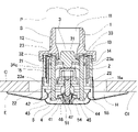
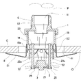
- FIG. 1 is a cross-sectional view of a sprinkler head of the present disclosure
- FIG. FIG. 2 is a cross-sectional view taken along line II-II shown in FIG. 1
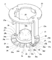
- It is a perspective view of a deflector unit.
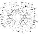
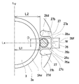
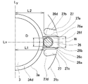
- FIG. 4 is a plan view of a deflector; 4 is an enlarged view of the vicinity of a pin (post) in FIG. 3;
- FIG. 4 is an exploded perspective view of the heat-sensitive actuating portion; It is a figure which shows the state at the time of water sprinkling in FIG. It is an enlarged view near the pin (support
- FIG. 11 is an enlarged view of the vicinity of pins (struts) of a plan view of another modified example of the deflector.
- FIG. 11 is an enlarged view of the vicinity of pins (struts) of a plan view of still another modified example of the deflector.
- the sprinkler head S has a body 1 , a deflector unit 2 , a valve cap 3 , a heat-sensitive operating portion 4 and a heat collector 5 .
- the sprinkler head S of this embodiment is a flush-type sprinkler head installed with a body 1 connected to a water supply pipe embedded in the ceiling.
- the body 1 has a hollow cylindrical shape and has a nozzle 11 inside.
- the nozzle 11 has a cylindrical shape and extends between one end side and the other end side of the body 1 in the cylinder axis direction (height direction, vertical direction).
- the "axial direction" of the nozzle 11 is also referred to as the "cylinder axial direction”.
- a male screw 12 connected to the water supply pipe P is installed on one end side of the body 1 .
- the other end of the body 1 has a flange portion 13 that expands outward, and a cylindrical frame 14 is screwed to the flange portion 13 .
- the frame 14 is installed on the outer peripheral side of the outlet end of the nozzle 11, and an inner Steps 15 are provided extending towards the circumference.
- the deflector unit 2 of FIG. 3 includes a deflector 21, a pin 22 as a support, and a guide ring 23.
- the deflector unit 2 is housed inside the frame 14 .
- the deflector 21 is disc-shaped and has a plurality of slits 24 on its peripheral edge (outer edge).
- the slit 24 is installed symmetrically with respect to an imaginary line Lx passing through the central axis of the pin 22 and the center of the deflector 21 .
- the slit 24 has a shape (tapered shape) whose width increases from the center side of the deflector 21 toward the open end 24a on the outer peripheral side (outer edge side).
- the taper angle is preferably 2 to 10°. In this embodiment, the angle of the taper shape is 5°.
- the center of the deflector 21 is a hole (center hole) penetrating in the plate thickness direction (in the cylinder axis direction of the body 1), and the valve cap 3 is rotatably installed in the hole.
- a closed end 24 b of the slit 24 on the center side of the deflector 21 is configured to overlap the outer edge of the valve cap 3 .
- a plurality of pins 22 are installed between the deflector 21 and the guide ring 23 .
- the sprinkler head S of this embodiment has two pins 22 .
- the pin 22 is inserted through a hole 21c (pin insertion hole) formed through the deflector 21 in the plate thickness direction (in the cylinder axis direction of the body 1) near the periphery thereof.
- the pin 22 is arranged adjacent to the outer edge 3 a of the valve cap 3 installed on the deflector 21 .
- One end (guide ring side end) of the pin 22 is fixedly connected to an annular guide ring 23 , and the other end (deflector side end) of the pin 22 is a flange 25 .
- the deflector 21 is slidably held between the guide ring 23 and the flange 25 .
- the flat surface 21a of the deflector 21 on the nozzle 11 side is recessed toward the heat-sensitive operating portion 4 from the flat surface 21a on the nozzle 11 side of the deflector 21 toward the outer edge 21b of the deflector 21 from the periphery of the hole 21c through which the pin 22 is inserted.
- a recess 26 is provided which is formed by The step between the bottom surface 26f of the recess 26 and the flat surface 21a, which is the general surface of the deflector 21, is a side wall 26a. is scattered from the outer edge 26b.
- the step of the recess 26 has the function of guiding the fire extinguishing liquid discharged from the nozzle 11 to the recess 26 .
- the bottom surface 26f of the recess 26 has a shape in which the flat surface 21a of the deflector 21 is recessed to protrude downward. may be formed.
- the plate thickness of the recess (bottom portion of the recess) in the plate thickness direction of the deflector 21 is formed thinner than the plate thickness of the peripheral portion of the recess.
- the outer edge 26b of the concave portion 26 is arranged inside the imaginary outer circumference circle of the deflector 21 indicated by the dashed line in FIG. 5, and is formed in a straight line. Therefore, the water is splashed in a large amount in a direction perpendicular to the linear outer edge 26b. Further, since the linear outer edge 26b of the recess 26 is arranged inside the imaginary outer circumference circle of the deflector 21, the flight distance of the water splashed from the recess 26 is greater than the flight distance of the water splashed from the outer edge of the deflector 21. is also shorter. Therefore, water can be sprayed in a short range from the place where the sprinkler head S is installed.
- the inner edge 26 d of the recess 26 is arranged so as to overlap the outer edge 3 a of the valve cap 3 .
- the outer edge 26b of the concave portion 26 is formed in a straight line. is not limited to linear.
- the width W of the recess 26 is preferably 1.2 to 1.5 times the diameter D of the pin 22. In this embodiment, it is configured to be about 1.3 times. As a result, the narrowed portion 26e is formed between the pin 22 and the side wall 26a of the recess 26, so that the flow rate of water passing through the narrowed portion 26e is increased.
- First slits 27 are provided on both sides of the recess 26 in the width direction.
- the first slit 27 has an open end 27c adjacent to the outer edge 26b of the recess 26, as shown in FIG.
- the first slit 27 has a first side 27a located on the pin 22 side and a second side 27b facing the first side 27a.
- the first side 27a is formed along the side wall 26a of the adjacent recess 26 and parallel to the imaginary line Lx.
- the second side 27b is formed so as to approach the first side 27a from the closed end side of the first slit 27 toward the open end side. That is, the second side 27b is inclined with respect to the imaginary line Lx, and is formed so as to intersect the imaginary line Lx when extended in the direction of the open end 27c of the first slit 27. .
- each of the first slits 27 has a second side 27b extending from the virtual line Lx so that when the second side 27b is extended in the direction of the open end 27c of the first slit 27, the second side 27b intersects with the virtual line Lx. leaning Therefore, since the width of the first slit 27 becomes narrower toward the outer edge of the deflector 21, the flow velocity of the inflowing water is increased, and the water splashed from the first slit 27 is directed along the extension of the virtual line Lx. It becomes possible to scatter in the direction in which the pin 22 is arranged.
- the first slits 27 are provided on both sides of the recess 26 in the width direction, so that the amount of water sprayed in the direction in which the pins 22 are arranged can be increased.
- the water flowing into the first slit 27 flows along the second side 27b and then flows in the direction perpendicular to the straight line connecting the open ends 27c. It will flow towards you.
- the slope 26c is installed by obliquely missing the corner between the outer edge 26b of the concave portion 26 and the first slit 27, the water flowing through the first slit 27 is promoted by the slope 26c in the direction of the imaginary line Lx. be able to
- the closed end 27d of the first slit 27 is spaced apart from the outer edge 3a of the valve cap 3, as shown in FIG. More specifically, the length L1 from the orthogonal virtual line Ly obtained by rotating the virtual line Lx by 90 degrees from the center of the deflector 21 to the outer periphery of the pin 22, and the length L1 from the orthogonal virtual line Ly to the closed end of the first slit 27. are configured to be substantially equal. If the first slit 27 is shallow and the relationship of length L1 ⁇ length L2 is satisfied, the water will be sprayed at a position far from the head in the back direction of the pin 22 .
- the length L1 is almost equal to the length L2.
- the outer diameter of the guide ring 23 is smaller than the inner diameter of the frame 14 and larger than the inner diameter of the step 15 . Therefore, the guide ring 23 is configured to be engaged with the step 15 after being dropped by the operation of the heat-sensitive operating portion 4 .
- An arm 23 a is installed on the outer edge of the guide ring 23 .
- the arm 23 a is installed parallel to the pin 22 and arranged adjacent to the pin 22 . More specifically, the arm 23a is arranged on a virtual plane (not shown) where the virtual line Lx and the axis of the nozzle 11 intersect.
- the length of arm 23 a is shorter than the length of pin 22 .
- the arm 23a is accommodated in a groove 15a formed in the step 15 of the frame 14. As shown in FIG.
- the groove 15 a is parallel to the axis of the nozzle 11 and acts as a guide when the guide ring 23 slides within the frame 14 .
- the side surface of the arm 23a is held by the groove 15a.
- the plane 21a of the deflector 21 is perpendicular to the central axis of the nozzle 11, and the deflection of the deflector 21 can be prevented.
- the guide ring 23 and the deflector 21 are prevented from moving in the circumferential direction.
- the groove 15 a is located at a position rotated 90° from the position where the lever 41 is engaged with the step 15 about the axis of the nozzle 11 .
- the valve cap 3 is formed in a disc shape having a projection on the nozzle 11 side.
- a plate-shaped saddle 31 is provided between the valve cap 3 and the lever 41 .
- the valve cap 3 closes the outlet end of the nozzle 11 by means of a lever 41 engaged with the step 15 and pushed through the saddle 31 to hold it in the outlet position of the nozzle 11 .
- a sealing member 32 is installed between the valve cap 3 and the outlet end of the nozzle 11 .
- the sealing member 32 is made of, for example, fluororesin.
- the seal member 32 may be installed at the valve cap 3 .
- the deflector 21 provided with the valve cap 3 placed thereon is arranged in the frame 14 at a position close to the guide ring 23 .
- a spring 33 is biased and installed between the guide ring 23 and the flange portion 13 . When the heat-sensitive operating portion 4 is actuated, the spring 33 promotes movement of the guide ring 23, the deflector 21 and the valve cap 3 from the frame 14 to the outside. It should be noted that the load of the spring 33 is less than the load pressing the valve cap 3 against the outlet end of the nozzle 11 .
- the valve cap 3 includes an annular flat portion 34a that contacts the outlet end of the nozzle 11, and an inner convex portion that is provided inside the flat portion 34a and protrudes toward the inside of the nozzle 11. 34b and an outer protrusion 34c protruding in the direction opposite to the inner protrusion 34b.
- An outer edge of the planar portion 34a is formed with an inclined surface 34d extending from the surface on the side of the inner convex portion 34b toward the outer edge.
- the shapes of the planar portion 34a, the inner convex portion 34b, and the inclined surface 34d affect the water spray pattern because the water discharged from the nozzles 11 collides with them when the sprinkler head is operated and flows on the surfaces thereof.
- the outer edge 3 a of the valve cap 3 is arranged so as to overlap the inner edge 26 d of the recess 26 . As a result, the water flows on the slope 34d of the valve cap 3 and flows into the recess 26 without reducing its momentum. Further, the outer edge 3a of the valve cap 3 is arranged so as to overlap the closed end 24b of the slit 24, so that the water flowing down the slope 34d of the valve cap 3 scatters downward from the slit 24 while maintaining its momentum. It is configured.
- the pin 22 is arranged adjacent to the outer edge 3 a of the valve cap 3 .
- the deflector 21 slides along the pin 22, so that the valve cap 3 is moved with a slight gap between the valve cap 3 and the pin 22. It has a configuration in which the outer edge 3a and the pin 22 are arranged close to each other.
- 1, 2, and 6 includes a pair of levers 41, a support plate 42, a balancer 43, a set screw 44, a cylinder 45, a plunger 46, and a fusible alloy 47. is configured with A known portion of the configuration of the heat-sensitive operating section 4 is described, for example, in Japanese Patent Application Laid-Open No. 2005-27929.
- the cylinder 45 is formed in a cylindrical shape with a bottom, and a male screw protrudes from its bottom surface.
- the inside of the cylinder 45 is filled with a fusible alloy 47 , and a plunger 46 is placed on the fusible alloy 47 , that is, on the side opposite to the bottom surface of the cylinder 45 .
- These members constitute the heat-sensitive elements of the heat-sensitive operating section 4 .
- a heat collector 5 is connected to the male thread. Thereby, the heat collector 5 is held by the body 1 so as to protrude from the lower end of the body 1 .
- the heat collector 5 has a bowl shape with a nut 51 attached in the center.
- the nut 51 is screwed onto the male thread 45 a of the cylinder 45 .
- the nut 51 has a large diameter end on the heat collector 5 side and a small diameter end on the cylinder 45 side.
- a step 54 is thereby formed in the middle of the nut 51 .
- the nut 51 is in direct contact with the bottom surface of the cylinder 45 at the end on the heat collector 5 side.
- the end of the nut 51 on the heat collector 5 side has a larger diameter than the end on the cylinder 45 side.
- the contact area between the heat collector 5 and the nut 51 is increased, so that stable bonding strength between the heat collector 5 and the nut 51 can be obtained.
- the contact area between the heat collector 5 and the nut 51 is larger than the end on the cylinder side, the heat absorbed by the heat collector 5 can be efficiently transferred to the nut 51 .
- the outer diameter of the end of the nut 51 is configured to be equal to or less than the diameter of the bottom surface of the cylinder 45.
- the outer diameter of the end of nut 51 is more preferably configured to be less than or equal to the inner diameter of cylinder 45 .
- a plurality of openings 55 are formed on the side surface of the heat collector 5 .
- the openings 55 are arranged along the entire side circumference of the heat collector 5 with uniform lengths and intervals. In the embodiment shown in FIG. 1, six openings 55 are provided.
- the number of openings 55 is greater than the number of levers 41 .
- the opening 55 can improve the efficiency of passing the airflow to the heat collector 5 .
- the height of the opening 55 is 2 to 5 mm
- the width of the opening 55 is 8 to 12 mm. According to such a configuration, the airflow heated by the fire flows into the heat collector 5 from the opening 55, so the heat collector 5 can also absorb heat from the inside.
- the escutcheon E includes a dish portion E1 that covers the hole H between the ceiling C and the sprinkler head S, and a cylindrical portion E2 that extends from the inner edge of the dish portion E1 and engages the frame 14. there is
- the plate portion E1 is configured such that an outer peripheral edge extending outward from the lower end of the cylindrical portion E2 can come into contact with the ceiling surface C1.
- the sprinkler head S is installed with the body 1 screwed to the water supply pipe P and the heat collector 5 exposed from the ceiling C to the indoor side.
- a hole H through which the sprinkler head S can be inserted is formed in the ceiling C, and an escutcheon E is installed to cover the hole H.
- the plunger 46 moves toward the bottom surface of the cylinder 45 to loosen the engagement between the balancer 43 and the lever 41 , and the lower end of the lever 41 rotates and comes off the balancer 43 .
- the lever 41 is further rotated and dropped from the step 15 of the frame 14 . Furthermore, the saddle 31 and the valve cap 3 placed on the lever 41 also drop out of the frame 14 .
- the deflector unit 2 in which the valve cap 3 is incorporated slides in the frame 14 and moves in the direction of the step 15 so that the outer edge side of the guide ring 23 is engaged with the step 15 by the action of the spring 33 .
- the deflector 21 and the valve cap 3 move downward in the figure along the pin 22 and are locked to the collar 25 .
- the deflector 21 and the valve cap 3 are suspended below the frame 14 by the pins 22 .
- the water that collides with the valve cap 3 flows on its surface, passes through the surface of the deflector 21, and is splashed onto the floor surface.
- the water flowing around the pin 22 flows into the recess 26 from the inclined surface 34 d on the outer edge 3 a side of the valve cap 3 without passing through the surface of the deflector 21 .
- the flow velocity increases and the water is rectified by the side wall 26a and splashes from the outer edge 26b of the recess 26.
- the water is splashed in a direction perpendicular to the straight outer edge 26b of the recess 26, and the flying distance is closer to the sprinkler head S than the water splashed from the outer edge 21b of the deflector 21.
- the water that has passed through the first slit 27 adjacent to the recess 26 increases in flow velocity and flows along the extension of the virtual line Lx, thereby increasing the amount of water sprinkled on the back of the pin 22 .
- the recess 26 is provided from the periphery of the pin 22 in the deflector 21 toward the outer edge 21b, and the first slits 27 are provided on both sides of the recess 26 in the width direction.
- the water that has flowed from the valve cap 3 to the slit 24 is sprayed on the floor in a range near the position where the sprinkler head S is installed.
- the slit 24 has a tapered shape whose width widens toward the open end 24a. Therefore, the water flowing through the slit 24 spreads along the taper and scatters. As a result, the amount of water sprinkled in the range near the sprinkler head S increases, and a watering pattern in which the unevenness of the amount of water sprinkled is suppressed can be obtained.
- the water splashed onto the floor from the outer edge 21b of the deflector 21 is sprayed on the floor in a range far from the position where the sprinkler head S is installed.
- the water that collides with the deflector 21 scatters evenly on the floor surface in all directions, suppressing and suppressing the fire.
- the closed end 24b of the slit 24 overlaps the outer edge 3a of the valve cap 3, and the water flowing on the surface of the valve cap 3 directly flows into the slit 24 from the slope 34d. Furthermore, the water splashed from the slits 24 is sprayed closer to the sprinkler head S as the height dimension of the inner convex portion 34b of the valve cap 3 is increased.
- the height dimension from the flat portion 34a to the top portion of the inner convex portion 34b is preferably 2 to 3 times the height dimension from the rear surface of the flat portion 34a facing the deflector 21 to the flat portion 34a, which is the present embodiment. is configured to be 2.5 to 2.8 times.
- the water splashed from the outer edge 26b of the recess 26 is sprayed at a position near the sprinkler head S because the outer edge 26b is arranged inside the virtual outer circle of the deflector 21.
- the position of the outer edge 26b is brought close to the outer diameter of the deflector 21, water can be sprayed to a farther position.
- the amount of water sprinkled at positions near the sprinkler head S can be increased.
- the shape of the deflector of the sprinkler head is not limited to the embodiments shown in FIGS. That is, the deflector has a recess that is recessed from the nozzle-side surface of the deflector from the periphery of the pin on the nozzle-side surface of the deflector toward the outer edge of the deflector, and the first slits are formed on both sides of the recess in the width direction. provided, and the open end of the first slit is provided adjacent to the outer edge of the recess.
- the first side 27a of the first slit 27 is parallel to the second side 27b, the first side 27a is inclined with respect to the virtual line Lx, and the first side 27a may be formed so as to cross the virtual line Lx when extended in the direction of the open end 27c.
- the position of the open end 27c is provided adjacent to the recess 26 in the width direction with respect to the arrangement of the first slit 27. For example, the amount of water sprayed in the direction in which the pins 22 are arranged can be increased.
- the second side 27b of the first slit 27 may be arranged in parallel with the first side 27a in a direction parallel to the virtual line Lx. As described above, even if the second side 27b is arranged in the direction parallel to the imaginary line Lx, the position of the open end 27c of the first slit 27 is adjacent to the recess 26 in the width direction. If it is the structure provided in each direction, the amount of water sprayed in the direction in which the pin 22 is arrange
- the outer edge 26b of the concave portion 26 may be arranged slightly outside the virtual outer circumference circle of the deflector 21. Further, as shown in FIG. Thus, even if the outer edge 26b of the recess 26 is arranged slightly outside the virtual outer circumference of the deflector 21, the position of the open end 27c of the first slit 27 is adjacent to the recess 26 in the width direction. With the configuration provided, it is possible to increase the amount of water sprayed in the direction in which the pin 22 is arranged.
Landscapes
- Health & Medical Sciences (AREA)
- Public Health (AREA)
- Business, Economics & Management (AREA)
- Emergency Management (AREA)
- Fire-Extinguishing By Fire Departments, And Fire-Extinguishing Equipment And Control Thereof (AREA)
Abstract
Description
Claims (15)
- 消火液を放出するノズルを有するボディと、
前記ノズルを閉止するバルブキャップと、
前記ノズルに対する前記バルブキャップの閉止状態を保持し、分解作動時に前記閉止状態を開放する感熱作動部と、
前記ノズルから放出される前記消火液を前記ノズルの軸交差方向で外向きに飛散させる円盤状のデフレクターと、
前記デフレクターを支持する支柱と、を備えるスプリンクラーヘッドであり、
前記デフレクターの前記ノズル側の面には、前記支柱の周囲から前記デフレクターの外縁に向けて、前記デフレクターの前記ノズル側の面に対して窪んで形成されている凹部を有しており、
前記凹部の幅方向の両隣には、開放端が前記凹部の外縁に隣接して設けられている第1スリットを有するスプリンクラーヘッド。 - 前記第1スリットの幅は、前記デフレクターの中心側から前記外縁側に向かうに従い狭くなる
請求項1記載のスプリンクラーヘッド。 - 前記第1スリットは、前記支柱側に位置する第1の辺と、前記第1の辺と対向する第2の辺とを有しており、
前記第1の辺は、隣接する前記凹部の側壁に沿って形成されており、
前記第2の辺は、第1スリットの閉鎖端側から開放端側に向けて前記第1の辺に近づくように形成されている
請求項1記載のスプリンクラーヘッド。 - 前記支柱は、前記デフレクターに設置された前記バルブキャップの外縁に隣接して配置されている
請求項1~請求項3何れか1項記載のスプリンクラーヘッド。 - 前記凹部の外縁は、前記デフレクターの仮想外周円よりも内側に配置されている
請求項1~請求項4何れか1項記載のスプリンクラーヘッド。 - 前記凹部の前記外縁は、直線状に形成されている
請求項1~請求項5何れか1項記載のスプリンクラーヘッド。 - 前記バルブキャップの前記外縁は、前記凹部の内縁に重なるように配置されている
請求項1~請求項6何れか1項記載のスプリンクラーヘッド。 - 前記凹部の幅は、前記支柱の直径に対して1.2~1.5倍に構成されている
請求項1~請求項7何れか1項記載のスプリンクラーヘッド。 - 前記凹部の外縁と前記第1スリットとの間の角は、斜めに欠如されている
請求項1~請求項8何れか1項記載のスプリンクラーヘッド。 - 前記デフレクターの外縁には、線状のスリットが複数形成されており、前記スリットの幅は、前記デフレクターの外周側の開放端に向かうに従い拡がるテーパー状となっている
請求項1~請求項9何れか1項記載のスプリンクラーヘッド。 - 前記スリットは、前記デフレクターの中心側の閉鎖端と前記バルブキャップの外縁とが重なって配置されている
請求項10記載のスプリンクラーヘッド。 - 前記支柱は、前記デフレクターとガイドリングの間に複数設置され、前記ガイドリングは前記ノズルの出口端の外周側に設置された筒状のフレーム内を摺動可能であり、前記フレーム内部の下端部に設置された段に係止される
請求項1~請求項11何れか1項記載のスプリンクラーヘッド。 - 前記ガイドリングの外縁には、前記支柱と平行にアームが設置されている
請求項12記載のスプリンクラーヘッド。 - 前記アームは、前記仮想線とノズルの軸が交差する平面上に配置されている
請求項13記載のスプリンクラーヘッド。 - 前記アームは、前記段に形成された前記ノズルの軸と平行な溝の内部に配置される
請求項13または請求項14記載のスプリンクラーヘッド。
Priority Applications (2)
| Application Number | Priority Date | Filing Date | Title |
|---|---|---|---|
| JP2023514594A JPWO2022220132A1 (ja) | 2021-04-15 | 2022-03-30 | |
| CN202280012063.1A CN116887891A (zh) | 2021-04-15 | 2022-03-30 | 喷洒头 |
Applications Claiming Priority (2)
| Application Number | Priority Date | Filing Date | Title |
|---|---|---|---|
| JP2021068870 | 2021-04-15 | ||
| JP2021-068870 | 2021-04-15 |
Publications (1)
| Publication Number | Publication Date |
|---|---|
| WO2022220132A1 true WO2022220132A1 (ja) | 2022-10-20 |
Family
ID=83639642
Family Applications (1)
| Application Number | Title | Priority Date | Filing Date |
|---|---|---|---|
| PCT/JP2022/016142 WO2022220132A1 (ja) | 2021-04-15 | 2022-03-30 | スプリンクラーヘッド |
Country Status (4)
| Country | Link |
|---|---|
| JP (1) | JPWO2022220132A1 (ja) |
| CN (1) | CN116887891A (ja) |
| TW (1) | TW202245877A (ja) |
| WO (1) | WO2022220132A1 (ja) |
Citations (7)
| Publication number | Priority date | Publication date | Assignee | Title |
|---|---|---|---|---|
| JP2001095944A (ja) * | 1999-10-04 | 2001-04-10 | Hochiki Corp | スプリンクラーヘッド及び消火設備並びにスプリンクラーヘッド性能評価方法 |
| JP2003062108A (ja) * | 2001-08-23 | 2003-03-04 | Senju Sprinkler Kk | 泡水溶液噴霧ヘッド |
| JP2004024555A (ja) * | 2002-06-26 | 2004-01-29 | Senju Sprinkler Kk | 埋込型スプリンクラーヘッド |
| JP2012040165A (ja) * | 2010-08-19 | 2012-03-01 | Senju Sprinkler Kk | スプリンクラーヘッド |
| JP2012080961A (ja) * | 2010-10-07 | 2012-04-26 | Senju Sprinkler Kk | スプリンクラーヘッド |
| KR20190098604A (ko) * | 2018-02-14 | 2019-08-22 | 주식회사 파라텍 | 물류창고용 스프링클러 헤드 |
| JP2019187774A (ja) * | 2018-04-25 | 2019-10-31 | 千住スプリンクラー株式会社 | スプリンクラーヘッド |
-
2022
- 2022-03-30 JP JP2023514594A patent/JPWO2022220132A1/ja active Pending
- 2022-03-30 WO PCT/JP2022/016142 patent/WO2022220132A1/ja active Application Filing
- 2022-03-30 CN CN202280012063.1A patent/CN116887891A/zh active Pending
- 2022-04-13 TW TW111114002A patent/TW202245877A/zh unknown
Patent Citations (7)
| Publication number | Priority date | Publication date | Assignee | Title |
|---|---|---|---|---|
| JP2001095944A (ja) * | 1999-10-04 | 2001-04-10 | Hochiki Corp | スプリンクラーヘッド及び消火設備並びにスプリンクラーヘッド性能評価方法 |
| JP2003062108A (ja) * | 2001-08-23 | 2003-03-04 | Senju Sprinkler Kk | 泡水溶液噴霧ヘッド |
| JP2004024555A (ja) * | 2002-06-26 | 2004-01-29 | Senju Sprinkler Kk | 埋込型スプリンクラーヘッド |
| JP2012040165A (ja) * | 2010-08-19 | 2012-03-01 | Senju Sprinkler Kk | スプリンクラーヘッド |
| JP2012080961A (ja) * | 2010-10-07 | 2012-04-26 | Senju Sprinkler Kk | スプリンクラーヘッド |
| KR20190098604A (ko) * | 2018-02-14 | 2019-08-22 | 주식회사 파라텍 | 물류창고용 스프링클러 헤드 |
| JP2019187774A (ja) * | 2018-04-25 | 2019-10-31 | 千住スプリンクラー株式会社 | スプリンクラーヘッド |
Also Published As
| Publication number | Publication date |
|---|---|
| JPWO2022220132A1 (ja) | 2022-10-20 |
| CN116887891A (zh) | 2023-10-13 |
| TW202245877A (zh) | 2022-12-01 |
Similar Documents
| Publication | Publication Date | Title |
|---|---|---|
| KR102158703B1 (ko) | 회전가능한 디플렉터가 구비된 스프링클러 헤드 | |
| US20210094051A1 (en) | Sprinkler Head | |
| WO2022220132A1 (ja) | スプリンクラーヘッド | |
| JP3498231B2 (ja) | スプリンクラーヘッド | |
| CN111699025A (zh) | 喷洒头 | |
| KR20200089395A (ko) | 방사형 유로가 형성된 디플렉터가 구비된 스프링클러 헤드 | |
| WO2023195046A1 (ja) | スプリンクラーヘッド | |
| JP7309495B2 (ja) | スプリンクラーヘッド | |
| JP2018166854A (ja) | スプリンクラーヘッド | |
| CN111386141B (zh) | 喷洒头 | |
| JP2016067509A (ja) | 消火用ヘッド | |
| KR102158704B1 (ko) | 날개부가 형성된 디플렉터가 구비된 스프링클러 헤드 | |
| JP7202041B2 (ja) | スプリンクラーヘッド | |
| JP3012031U (ja) | スプリンクラーヘッド | |
| JP7284166B2 (ja) | スプリンクラーヘッド | |
| JP3846591B2 (ja) | スプリンクラーヘッド | |
| JPH074825Y2 (ja) | スプリンクラヘッドのデフレクタ | |
| JP3014504U (ja) | フラッシュ型スプリンクラーヘッド | |
| JPH0313334Y2 (ja) | ||
| JP3016190U (ja) | フラッシュ型スプリンクラーヘッド | |
| JP2020130750A (ja) | スプリンクラヘッド | |
| JPH0350932Y2 (ja) | ||
| JP2020124290A (ja) | スプリンクラーヘッド | |
| JPH08173570A (ja) | スプリンクラーヘッド | |
| JP2012139252A (ja) | スプリンクラヘッド |
Legal Events
| Date | Code | Title | Description |
|---|---|---|---|
| 121 | Ep: the epo has been informed by wipo that ep was designated in this application |
Ref document number: 22788057 Country of ref document: EP Kind code of ref document: A1 |
|
| ENP | Entry into the national phase |
Ref document number: 2023514594 Country of ref document: JP Kind code of ref document: A |
|
| WWE | Wipo information: entry into national phase |
Ref document number: 202280012063.1 Country of ref document: CN |
|
| WWE | Wipo information: entry into national phase |
Ref document number: 18554882 Country of ref document: US |
|
| NENP | Non-entry into the national phase |
Ref country code: DE |
|
| 122 | Ep: pct application non-entry in european phase |
Ref document number: 22788057 Country of ref document: EP Kind code of ref document: A1 |