WO2022209078A1 - 作業機 - Google Patents
作業機 Download PDFInfo
- Publication number
- WO2022209078A1 WO2022209078A1 PCT/JP2021/048091 JP2021048091W WO2022209078A1 WO 2022209078 A1 WO2022209078 A1 WO 2022209078A1 JP 2021048091 W JP2021048091 W JP 2021048091W WO 2022209078 A1 WO2022209078 A1 WO 2022209078A1
- Authority
- WO
- WIPO (PCT)
- Prior art keywords
- outer peripheral
- peripheral surface
- striking
- feeder
- driver blade
- Prior art date
- Legal status (The legal status is an assumption and is not a legal conclusion. Google has not performed a legal analysis and makes no representation as to the accuracy of the status listed.)
- Ceased
Links
Images


Classifications
-
- B—PERFORMING OPERATIONS; TRANSPORTING
- B25—HAND TOOLS; PORTABLE POWER-DRIVEN TOOLS; MANIPULATORS
- B25C—HAND-HELD NAILING OR STAPLING TOOLS; MANUALLY OPERATED PORTABLE STAPLING TOOLS
- B25C1/00—Hand-held nailing tools; Nail feeding devices
- B25C1/001—Nail feeding devices
-
- B—PERFORMING OPERATIONS; TRANSPORTING
- B25—HAND TOOLS; PORTABLE POWER-DRIVEN TOOLS; MANIPULATORS
- B25C—HAND-HELD NAILING OR STAPLING TOOLS; MANUALLY OPERATED PORTABLE STAPLING TOOLS
- B25C1/00—Hand-held nailing tools; Nail feeding devices
- B25C1/04—Hand-held nailing tools; Nail feeding devices operated by fluid pressure, e.g. by air pressure
-
- B—PERFORMING OPERATIONS; TRANSPORTING
- B25—HAND TOOLS; PORTABLE POWER-DRIVEN TOOLS; MANIPULATORS
- B25C—HAND-HELD NAILING OR STAPLING TOOLS; MANUALLY OPERATED PORTABLE STAPLING TOOLS
- B25C7/00—Accessories for nailing or stapling tools, e.g. supports
Definitions
- the present invention relates to a work machine such as a nailer.
- Patent Document 1 describes a nailer in which a driver blade attached to a piston moves downward while being guided by a nose to strike a fastener.
- An object of the present invention is to provide a working machine with improved durability.
- a work machine is formed in a bar shape extending about an axis, and moves to one side in the axial direction to strike a fastener.
- the stopper is moved to the ejector by urging the stopper to the one side in the direction intersecting the axial direction, and by the injection portion that guides the movement of the striking portion to the one side in the axial direction.
- the hitting portion has a first portion and a second portion provided at a position different from the first portion in the axial direction, and the axial line of the first portion
- the outer peripheral surface on the supply portion side of the second portion does not protrude from the outer peripheral surface on the supply portion side with respect to the axis of the second portion, and the outer peripheral surface of the first portion on the side opposite to the supply portion with respect to the axis protrudes from the outer peripheral surface of the second portion on the side opposite to the supply portion with respect to the axis.
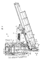
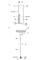
- FIG. 2 is a cross-sectional view of the nailing machine shown in FIG. 1 at a top dead center position;
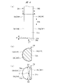
- FIG. 2 is an external view of a driver blade included in the nailing machine shown in FIG. 1;
- 4 is a view showing the structure of the driver blade shown in FIG. 3, where (a) is a partially enlarged view of the tip portion, (b) is a cross-sectional view along line BB in (a), and (c) is a C arrow view in (a).
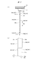
- FIG. 4 is an external view of the driver blade shown in FIG.
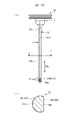
- FIG. 3 is a cross-sectional view of the nailing machine shown in FIG. 1 at a position between the top dead center and the bottom dead center;
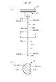
- FIG. FIG. 2 is a cross-sectional view of the nailing machine shown in FIG. 1 at a bottom dead center position;
- 2 is an enlarged partial cross-sectional view showing the structure of the nailing machine shown in FIG. 1 cut along line AA;
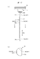
- FIG. It is a figure which shows the driver blade of the 1st modification in the nailing machine of this invention, (a) is an external view, (b) is an enlarged view of the front-end
- FIG. 11 is a view showing the driver blade shown in FIG. 10, where (a) is a cross-sectional view taken along line DD in FIG.
- FIG. 10 is a view showing a driver blade of a third modification in the nailing machine of the present invention, where (a) is an external view and (b) is a cross-sectional view taken along line EE in (a).
- 12A is an enlarged view of the tip portion of FIG. 12A
- FIG. 12B is a view of the driver blade shown in FIG. FIG.
- FIG. 10 is a view showing a driver blade of a fourth modification in the nailing machine of the present invention, (a) is an external view, and (b) is a cross-sectional view taken along line GG in (a). It is a figure which shows the driver blade shown in FIG. 14, (a) is an enlarged view of the front-end
- FIG. 10 is a view showing a driver blade of a fifth modification in the nailing machine of the present invention, where (a) is an external view and (b) is a sectional view taken along line II in (a). 16A is an enlarged view of the tip portion of FIG. 16A, and FIG.
- FIG. 16B is a view viewed from arrow J in FIG. 16A.
- FIG. 10 is a view showing a driver blade of a sixth modification in the nailing machine of the present invention, where (a) is an external view and (b) is a cross-sectional view taken along line KK in (a).
- 18A is an enlarged view of the tip portion of FIG. 18A
- FIG. 18B is a view viewed from arrow M in FIG.
- a work machine according to the present embodiment will be described with reference to the drawings.
- a nailing machine will be described as an example of a working machine.
- the same or equivalent elements shown in each figure are given the same reference numerals.
- the housing 11 has a body 18 , a handle 19 and a head cover 20 .
- the trunk portion 18 has a cylindrical shape, and the handle 19 is connected to the trunk portion 18 .
- the head cover 20 is fixed to one longitudinal end of the body 18 and closes the opening of the body 18 .
- the injection section 12 is also called a nose and is fixed to the other longitudinal end of the body section 18 .
- a plug 21 is provided on the handle 19 and an air hose is connected to the plug 21 .
- a cylinder 22 is provided inside the body portion 18 .
- the cylinder 22 is movable relative to the housing 11 in the direction along the centerline A1.
- a centerline A1 is the centerline of the cylinder 22 .
- the striking part 13 is arranged over the inside and outside of the cylinder 22 .
- the striking part 13 is operable with respect to the cylinder 22 in the direction along the center line A1.
- a pressure accumulation chamber 23 is provided in the handle 19 , the body portion 18 , and the head cover 20 . Compressed air supplied from the air hose is accumulated in the pressure accumulation chamber 23 .
- the head cover 20 also has a passageway 24 and an exhaust valve chamber 26 .
- Passage 24 is connected to the outside of housing 11 .
- a mount portion 27 is attached to the head cover 20 .
- Mount portion 27 has passages 28 and passages 29 .
- Passageway 29 is connected to passageway 24 via passageway 28 .
- Mount portion 27 supports exhaust valve 30 .
- the exhaust valve 30 is movable relative to the mount portion 27 in the direction along the center line A1. When the exhaust valve 30 operates, the passage 29 is opened and closed.
- a valve seat 31 is attached to the mount portion 27 .
- the valve seat 31 is made of synthetic rubber and has a piston upper chamber 32 .
- the piston upper chamber 32 communicates with the passageway 29 .
- the striking part 13 has a piston 33 and a driver blade 34 .
- Piston 33 is provided within cylinder 22 and is operable relative to cylinder 22 in a direction along center line A1.
- the pressure in the piston upper chamber 32 forces the piston 33 away from the valve seat 31 in the direction along the center line A1.
- a seal member 25 is attached to the outer peripheral surface of the piston 33 .
- the seal member 25 contacts the inner peripheral surface of the cylinder 22 .
- the driver blade 34 attached to the piston 33 moves to one side (stopper projecting side) in the axial direction 34e in FIG. 1, which is the direction along the axis 34d of the driver blade 34 shown in FIG. (stopper) 16 is a member that hits.
- a piston lower chamber 35 is provided between the piston 33 and the ejection portion 12 in the direction along the center line A1 inside the cylinder 22 .
- the seal member 25 seals the piston lower chamber 35 .
- a return air chamber 36 is also provided between the barrel 18 and the cylinder 22 .
- Passages 37 and 38 are provided that penetrate the cylinder 22 in the radial direction.
- a check valve 41 is provided on the outer peripheral surface of the cylinder 22 . The check valve 41 is actuated by the pressure inside the cylinder 22 and opens and closes the passage 37 .
- a passage 38 always connects the lower piston chamber 35 and the return air chamber 36 .
- the passageway 38 is arranged between the passageway 37 and the injection section 12 in a direction along the centerline A1.
- a bumper 39 is provided inside the cylinder 22 .
- the bumper 39 is arranged in the cylinder 22 at a position closest to the injection section 12 in the direction of the center line A1.
- the bumper 39 is made of synthetic rubber or silicon rubber.
- the bumper 39 has an axial hole 40, and the driver blade 34 can move in the axial hole 40 in the direction of the center line A1.
- a piston lower chamber 35 is formed between the piston 33 and the bumper 39 in the cylinder 22 .
- the ejection section 12 is fixed to the body section 18 and has an ejection path 43 .
- the injection path 43 is connected to the shaft hole 40 .
- the driver blade 34 is movable in the axial hole 40 and the injection path 43 in the direction along the centerline A1.
- the ejection portion 12 contacts the outer peripheral surface 34f of the driver blade 34 shown in FIG. 3, thereby guiding the movement of the driver blade 34 to one side (stopper projecting side) in the axial direction 34e.
- a push lever 15 is attached to the injection section 12 .
- the push lever 15 is operable with respect to the housing 11 and the injection section 12 in the direction along the center line A1.
- the push lever 15 is biased away from the housing 11 by a spring 42 as a biasing member.
- the push lever 15 biased by the spring 42 comes into contact with the stopper 44 and stops at the initial position.
- the push lever 15 can operate in a direction to approach the housing 11 against the biasing force of the spring 42 .
- a magazine 45 is also attached to the nailer 10 .
- the magazine 45 can accommodate a plurality of nails 16 as fasteners.
- a magazine 45 is supported by the ejection section 12 and the handle 19 .
- the magazine 45 is provided with a feeder 46 as a supply portion for the nails 16 and a spring 47.
- the spring 47 extends through the feeder 46 in a direction intersecting the axial direction 34e of the driver blade 34 (hereinafter referred to as this direction).
- the nail 16 is urged to one side (injection part side) of the urging direction B1). That is, the feeder 46 feeds the nail 16 to the injection path 43 by the biasing force of the spring 47 .
- the push lever 15 When the striking part 13 strikes the nail 16 into the mating member 17 and the push lever 15 is separated from the mating member 17 by the recoil, the push lever 15 is actuated by the biasing force of the spring 42 and stops at the initial position. Then, the compressed air in the exhaust valve chamber 26 is discharged to the outside. Furthermore, the exhaust valve 30 operates to connect the passage 29 and the passage 28, and the compressed air in the piston upper chamber 32 is discharged to the outside. When the pressure in the piston upper chamber 32 drops, the piston 33 rises due to the pressure of the compressed air supplied from the return air chamber 36 to the piston lower chamber 35 . Then, the piston 33 comes into contact with the valve seat 31, and the striking portion 13 stops at the top dead center.
- the driver blade 34 included in the nailing machine 10 of this embodiment will be described.
- the driver blade 34 is a member that forms the striking portion 13 together with the piston 33, and is shaped like a rod extending about an axis 34d.
- the driver blade 34 has a first portion and a second portion provided at a different position from the first portion in the axial direction 34e.
- the driver blade 34 has a third portion provided at a different position from the first portion and the second portion in the axial direction 34e. That is, the driver blade 34 has a first portion, a second portion, and a third portion provided at different positions in the axial direction 34e.
- the first portion and the second portion are provided on one side of the axial direction 34e (stopper projecting side) from the third portion.
- the first portion is the tip portion 34a of the driver blade 34
- the second portion is the central portion 34b
- the third portion is the root portion 34c. Therefore, the central portion 34b, which is the second portion, is positioned between the tip portion 34a, which is the first portion, and the root portion 34c, which is the third portion.
- a tip portion outer peripheral surface 34g which is an outer peripheral surface 34f positioned on the feeder 46 side (see FIG. 2) with respect to the axis 34d of the tip portion 34a, is an outer peripheral surface on the feeder 46 side with respect to the axis 34d of the central portion 34b. It does not protrude from the central outer peripheral surface 34i, which is 34f.
- the tip portion outer peripheral surface 34g and the center portion outer peripheral surface 34i are flat surfaces having the same height as shown in FIGS. 4(a) and 4(b).
- a tip portion outer peripheral surface 34h which is an outer peripheral surface 34f located on the opposite side of the feeder 46 with respect to the axis 34d of the tip portion 34a (hereinafter also referred to as the opposite side of the feeder), is as shown in FIGS. Furthermore, it protrudes from a central portion outer peripheral surface 34j, which is an outer peripheral surface 34f on the side opposite to the feeder with respect to the axis 34d of the central portion 34b.
- the tip portion outer peripheral surface 34h may protrude from the center portion outer peripheral surface 34j with respect to the axis 34d.
- the cross-sectional shape of the tip portion 34a in the direction perpendicular to the axial direction 34e consists of an arc shape and a straight line, as shown in FIG. 4(b). That is, a distal end outer peripheral surface 34h of the distal end portion 34a on the side opposite to the feeder is an arc-shaped surface, while a distal end portion outer peripheral surface 34g of the distal end portion 34a on the feeder 46 side is a flat surface. Similarly, the central outer peripheral surface 34j of the central portion 34b on the side opposite to the feeder is an arc-shaped surface, while the central outer peripheral surface 34i of the central portion 34b on the feeder 46 side is a flat surface. .
- the distal end outer peripheral surface 34h which is an arc-shaped surface on the side opposite to the feeder, protrudes from the central outer peripheral surface 34j, which is also an arc-shaped surface, with respect to the axis 34d.
- the shape of the cross section in the direction perpendicular to the axial direction 34e of the tip portion 34a and the central portion 34b are similar shapes.
- the circle that forms the arcuate outer peripheral surface 34h of the tip end portion 34a on the side opposite to the feeder and the circle that forms the arcuate outer peripheral surface 34j of the center portion 34b on the side opposite to the feeder are shown in the figure. As shown in 4(c), they are circles having the same center C1.
- a tip outer peripheral surface 34g of the tip portion 34a on the feeder 46 side and a center portion outer peripheral surface 34i of the center portion 34b on the feeder 46 side are flat surfaces having the same height. Therefore, the shape of the cross section of the tip portion 34a and the center portion 34b in the direction perpendicular to the axial direction 34e are similar shapes.
- the amount of protrusion of the distal end portion outer peripheral surface 34h with respect to the center portion outer peripheral surface 34j is 0.05% or more and less than 0.5% with respect to the length L2 of the axial direction 34e of the center portion 34b shown in FIG. Preferably.
- the amount of protrusion of the tip portion outer peripheral surface 34h with respect to the central portion outer peripheral surface 34j is about 0.05 mm to about 0.5 mm. .
- the diameter D1 of the circle at the center C1 forming the outer peripheral surface 34h of the distal end portion, which is an arc-shaped surface, is 7.0 mm.
- the diameter D2 of the circle of the center C1 forming the outer peripheral surface 34j is 6.6 mm to 6.8 mm.
- the amount of protrusion of the tip portion outer peripheral surface 34h with respect to the center portion outer peripheral surface 34j is 0.1 mm to 0.2 mm, which is within the range of about 0.05 mm to less than about 0.5 mm.
- the root portion outer peripheral surface 34k which is the outer peripheral surface 34f positioned on the feeder 46 side with respect to the axis 34d of the root portion 34c, is the central portion, which is the outer peripheral surface 34f on the feeder 46 side with respect to the axis 34d of the central portion 34b. It does not protrude from the outer peripheral surface 34i. Similar to the relationship between the tip portion 34a and the center portion 34b, in the driver blade 34 shown in FIG. 3, the root portion outer peripheral surface 34k and the center portion outer peripheral surface 34i are flat surfaces having the same height.
- the root outer peripheral surface 34m which is the outer peripheral surface 34f positioned on the anti-feeder side with respect to the axis 34d of the root 34c, is on the anti-feeder side with respect to the axis 34d of the central portion 34b, similar to the relationship between the tip 34a and the central portion 34b. It protrudes from the central portion outer peripheral surface 34j, which is the outer peripheral surface 34f of the .
- the root portion outer peripheral surface 34m may protrude from the central portion outer peripheral surface 34j with respect to the axis 34d.
- the cross-sectional shape of the root portion 34c in the direction orthogonal to the axial direction 34e is also composed of arcs and straight lines, and is the same as the cross-sectional shape of the tip portion 34a. That is, the root portion outer peripheral surface 34m, which is the outer peripheral surface 34f of the root portion 34c, is an arcuate surface.
- the root portion outer peripheral surface 34m which is an arc-shaped surface on the side opposite to the feeder, is positioned relative to the axis 34d from the center portion outer peripheral surface 34j, which is also an arc-shaped surface. Protruding.
- the amount of protrusion of the root outer peripheral surface 34m with respect to the central outer peripheral surface 34j is also 0.1 mm to 0.2 mm.
- the outer peripheral surface 34f of the center portion 34b on the anti-feeder side is recessed from the outer peripheral surfaces 34f of the tip portion 34a and the root portion 34c on the anti-feeder side. That is, the outer peripheral surface 34f of the driver blade 34 on the side opposite to the feeder has a stepped shape, and the center portion 34b is thinner than the tip portion 34a and the root portion 34c.
- the feeder 46 side of the driver blade 34 there is no level difference from the root portion 34c to the central portion 34b and the tip portion 34a, and the flat surface has the same height.
- the outer peripheral surface 34f on the side opposite to the feeder that is, the outer peripheral surface 34f on the side opposite to the feeder of the central portion 34b is located on the opposite side of the tip portion 34a and the root portion 34c. The reason why it is recessed from the outer peripheral surface 34f of is explained.
- the feeder 46 always pushes the nails 16 accommodated in the magazine 45 along the biasing direction B1 intersecting the axial direction 34e. Pushing to 13. Specifically, the feeder 46 presses another nail 16 against the striking portion 13 along the biasing direction B1 that intersects with the axial direction 34e while the striking portion 13 is striking the nail 16 . As a result, the nail 16 to be struck next is pressed against the driver blade 34 by the feeder 46 even while the striking part 13 is moving to strike the nail 16 . 4(c) and 5, the driver blade 34 is tapered toward the tip so as not to hit the nail 16 waiting to be hit next at the same time. A portion 34p is provided.
- the driver blade 34 is pressed against the feeder side by the pressing force of the nail 16 on standby and comes into contact with the inner wall 12 a of the injection section 12 . while moving toward the projecting side.
- the outer peripheral surfaces 34f on the anti-feeder side of the tip portion 34a and the root portion 34c protrude from the outer peripheral surface 34f on the anti-feeder side of the central portion 34b. It is possible to prevent the outer peripheral surface 34f from coming into contact with the inner wall 12a of the injection section 12. As shown in FIG.
- the central portion 34b of the driver blade 34 and the inner wall 12a of the injection portion 12 slide at high speed, heat is generated, and generation of a deteriorated layer on the surface of the central portion 34b of the driver blade 34 can be prevented.
- the amount of protrusion of the tip outer peripheral surface 34h with respect to the central outer peripheral surface 34j is 0.05% or more and less than 0.5% with respect to the length L2 of the central portion 34b of the driver blade 34. While avoiding the contact of the driver blade 34j with the inner wall 12a of the injection section 12, it is possible to suppress the reduction in the durability of the driver blade 34 due to the reduction in the diameter D2 of the central outer peripheral surface 34j.
- the flat surface has the same height.
- the outer peripheral surface 34k of the side tip portion and the outer peripheral surface 34g of the feeder 46 side of the tip portion 34a do not protrude from the outer peripheral surface 34i of the feeder 46 side of the central portion 34b. Nails 16 are supplied from the magazine side. Therefore, since the feeder 46 side of the driver blade 34 is a flat surface, it is possible to prevent the head of the nail 16 from being caught in the steps of the driver blade 34, causing vibration and adversely affecting the driving operation of the driver blade 34. .
- the shape of the tip 34a needs to be shared with existing nailers to some extent. If an attempt is made to provide a step between the outer peripheral surface 34f of the center portion 34b, the diameter of the central portion 34b must be reduced.
- the front end outer peripheral surface 34h on the side opposite to the feeder 46 protrudes from the central outer peripheral surface 34j on the side opposite to the feeder 46 in the central portion 34b
- the front end outer peripheral surface 34g on the feeder 46 side protrudes from the feeder 46 side in the central portion 34b.
- the driver blade 34 may be easily damaged from the central portion 34b regardless of the presence or absence of deterioration in the central portion 34b.
- the outer peripheral surface 34g of the tip portion on the side of the feeder 46 does not protrude from the outer peripheral surface 34i of the central portion 34b on the side of the feeder 46, and the diameter of the central portion 34b is excessively small. Therefore, damage to the central portion 34b can be suppressed.
- the lower end surface 34n of the driver blade 34 includes a striking surface 34q for striking the nail 16.
- the striking surface 34q is inclined with respect to the axis 34d shown in FIG. 3 so that the lower end on the side of the feeder 46 protrudes from the lower end on the side opposite to the feeder toward one side (stopper projecting side) in the axial direction 34e. formed.
- the striking surface 34q is inclined at an angle of 5° with respect to the axis 34d shown in FIG. It is for moving while contacting the inner wall 12a of the injection part 12 .
- the inner wall 12a of the ejection section 12 is provided with a U-groove 12b recessed toward the side opposite to the feeder.
- the tip of the nail 16 is moved while contacting the U-groove 12b, so that the tip of the nail 16 can be driven into the desired position of the mating member 17 shown in FIG. .
- the reaction from the nail 16 at the time of striking is the feeder 46 of the central portion 34b of the driver blade 34.
- a stress is applied to the non-feeder side of the central portion 34b of the driver blade 34 so that the non-feeder side extends. Due to the influence of this stress, the central portion 34b of the driver blade 34 on the side opposite to the feeder is easily damaged.
- the nail 16 is pressed against the driver blade 34 by the feeder 46 so that the central portion 34b of the driver blade 34 is in a state where it is easy to abut against the inner wall 12a of the injection section 12 .
- the outer peripheral surface 34f of the central portion 34b on the anti-feeder side is the tip portion 34a and the root portion. Since the portion 34c is recessed from the outer peripheral surface 34f on the side opposite to the feeder, the outer peripheral surface 34f of the central portion 34b and the inner wall 12a of the injection portion 12 can be prevented from sliding at high speed. That is, it is important to provide a step on the side opposite to the feeder of the driver blade 34, so that damage to the central portion 34b of the driver blade 34 can be prevented. As a result, the durability of the driver blade 34 can be improved.
- At least one of the tip portion 34a and the root portion 34c abuts the inner wall 12a of the injection portion 12 at the top dead center position of the striking portion 13. Even at the dead center position, either one of the tip portion 34a and the root portion 34c contacts the inner wall 12a of the ejection portion 12.
- the central portion 34b of the driver blade 34 can be prevented from coming into contact with the inner wall 12a of the injection section 12.
- FIG. Further, for example, in the example of the state in which the striking portion 13 reaches the bottom dead center shown in FIG. It abuts on the inner wall 12a. Therefore, even in this state, the central portion 34b of the driver blade 34 can be prevented from coming into contact with the inner wall 12a of the injection section 12. As shown in FIG.
- the tip portion 34a of the driver blade 34 protrudes from the injection portion 12 by a length L when the hitting portion 13 reaches the bottom dead center. Therefore, the projection length L of the tip portion 34a of the driver blade 34 from the injection portion 12 when the striking portion 13 reaches the bottom dead center, the length L1 of the tip portion 34a of the driver blade 34 shown in FIG. By making the relationship L ⁇ L1, at least the tip portion 34a of the driver blade 34 can be accommodated in the ejection portion 12 when the hitting portion 13 reaches the bottom dead center.
- the tip portion 34a of the driver blade 34 can be brought into contact with the inner wall 12a of the ejection portion 12, and the central portion 34b of the driver blade 34 can be brought into contact with the ejection portion 12. contact with the inner wall 12a of the .
- both the tip portion 34a and the root portion 34c of the driver blade 34 are accommodated in the injection portion 12 as shown in FIG.
- this further prevents the central portion 34 b of the driver blade 34 from contacting the inner wall 12 a of the injection section 12 .
- the tip portion 34a contacts the inner wall 12a of the ejection portion 12 even when the striking portion 13 is positioned between the top dead center position and the bottom dead center position.
- the central portion 34b of the driver blade 34 is possible to prevent the central portion 34b of the driver blade 34 from coming into contact with the inner wall 12a of the injection portion 12 .
- the tip portion 34 a and the root portion 34 c of the driver blade 34 is inside the injection portion 12 .
- the striking part 13 is arranged at the top dead center position, the bottom dead center position, or any position between the top dead center position and the bottom dead center position. However, it is sufficient that at least one of the tip portion 34a and the root portion 34c of the driver blade 34 is housed in the ejection portion 12. As shown in FIG.
- the distal end outer peripheral surface 34h on the side opposite to the feeder protrudes from the central outer peripheral surface 34j on the side opposite to the feeder, and the feeder 46 side
- the tip outer peripheral surface 34g is recessed from the central outer peripheral surface 34i on the feeder 46 side.
- the feeder 46 side outer peripheral surface 34f if the feeder 46 side tip outer peripheral surface 34g does not protrude from the feeder 46 side central outer peripheral surface 34i of the central portion 34b, the tip portion 34a and the central portion 34b have the same height. need not be a flat surface. Even if the tip outer peripheral surface 34g on the feeder 46 side is recessed from the central outer peripheral surface 34i on the feeder 46 side as in the first modification, the diameter of the central portion 34b does not become excessively small. damage can be suppressed.
- the distal end outer peripheral surface 34h on the side opposite to the feeder protrudes from the central outer peripheral surface 34j on the opposite side to the feeder.
- a U-shaped groove portion 34r is provided in the central portion 34b on the side opposite to the feeder.
- This groove portion 34r is fitted to a rail portion 12c formed in the injection portion 12 and shown in FIG. 11(b). That is, by fitting the groove portion 34r to the rail portion 12c of the ejection portion 12, the vertical movement of the driver blade 34 is guided by the rail portion 12c.
- this driver blade 34 by providing the stepped portion 34s in the groove portion 34r on the side opposite to the feeder of the central portion 34b, it is possible to prevent the groove portion 34r of the central portion 34b from being deteriorated due to friction with the rail portion 12c. However, even if the groove portion 34r of the central portion 34b is degraded, there is little possibility that the driver blade 34 will be damaged due to the characteristics of the impact at the time of driving. good.
- a driver blade 34 of a third modified example shown in FIGS. 12(a) and 12(b) has a shape in which a concave portion 34t is provided on an outer peripheral surface 34f of a central portion 34b on the side opposite to the feeder.
- the recess 34t is elongated only in the center portion 34b on the side opposite to the feeder, and is not provided in the tip portion 34a and the root portion 34c. Therefore, the center peripheral surface 34j on the side opposite to the feeder is recessed from the tip peripheral surface 34h on the feeder side because the concave portion 34t is provided.
- a driver blade 34 of a fourth modified example shown in FIGS. 14(a) and 14(b) has a plurality of longitudinal ribs elongated along an axial direction 34e on an outer peripheral surface 34f of a distal end portion 34a on the side opposite to the feeder. 34u is provided. As shown in FIGS. 15(a) and 15(b), the vertical ribs 34u are provided only on the tip portion 34a on the side opposite to the feeder, and are not provided on the central portion 34b and the root portion 34c on the side opposite to the feeder. .
- a portion (longitudinal rib 34u) of the distal end portion 34a on the side opposite to the feeder protrudes from the outer peripheral surface 34j of the central portion on the side opposite to the feeder.
- the vertical rib 34u may also be provided on the root portion 34c.
- the driver blade 34 of the fifth modification shown in FIGS. 16(a) and 16(b) is formed so as to intersect the axial direction 34e on the arcuate portion of the outer peripheral surface 34f on the side opposite to the feeder of the tip portion 34a.
- a plurality of circumferential ribs 34v are provided. As shown in FIGS. 17A and 17B, the circumferential rib 34v is provided only on the tip portion 34a, and is not provided on the central portion 34b and the root portion 34c. As a result, a portion (circumferential rib 34v) of the distal end portion 34a on the side opposite to the feeder protrudes from the outer peripheral surface 34j of the central portion on the side opposite to the feeder. Note that the circumferential rib 34v may also be provided on the root portion 34c.
- a driver blade 34 of a sixth modification shown in FIGS. 18(a) and 18(b) has a plated film 34w formed on an arcuate portion of an outer peripheral surface 34f on the side opposite to the feeder of a central portion 34b. .
- the plated film 34w is formed only on the center portion 34b, and is not formed on the tip portion 34a and the root portion 34c.
- the plating film 34w on the tip part 34a and the root part 34c is peeled off, and the plating film 34w on the central part 34b is peeled off.
- the plated film 34w is automatically left only on the side opposite to the feeder.
- the same base material as in the first method is used, and the tip portion 34a and the root portion 34c are masked during plating, so that the plated film 34w is formed only on the side opposite to the feeder of the central portion 34b. It is a way to
- the driver blade 34 of the sixth modification is recessed from the outer peripheral surface 34h of the tip portion on the feeder side. That is, it is sufficient that the central outer peripheral surface 34j of the base material of the driver blade 34 on the side opposite to the feeder is recessed from the tip outer peripheral surface 34h and the root outer peripheral surface 34m of the base material.
- the surface of 34w may protrude from, be recessed from, or be flush with the tip outer peripheral surface 34h and root outer peripheral surface 34m on the opposite feeder side.
- the outer peripheral surface 34f on the side opposite to the feeder of either the tip portion 34a or the root portion 34c is opposite to the central portion 34b. It protrudes from the outer peripheral surface 34f on the feeder side.
- the outer peripheral surface 34f of the center portion 34b on the side opposite to the feeder is recessed from at least a portion of the outer peripheral surface 34f on the side opposite to the feeder of either the tip portion 34a or the root portion 34c.
- the durability of the driver blade 34 can be improved in the driver blades 34 of the first to sixth modifications as well.
- the present invention is not limited to the above embodiments, and can be modified in various ways without departing from the scope of the invention.
- the first portion of the driver blade 34 is the tip portion 34a
- the second portion is the central portion 34b
- the first portion is located on one side of the axial direction 34e (stopper protruding side) relative to the second portion. ) is placed in the
- the first portion and the second portion may be at different positions in the axial direction 34 e of the driver blade 34 . Therefore, the first portion may be arranged on the other side in the axial direction 34e (opposite side to the stopper projecting side) of the second portion.
- the durability of the driver blade 34 can be improved by avoiding the outer peripheral surface 34f of the center portion 34b on the side opposite to the feeder from coming into contact with the inner wall 12a of the injection portion 12 .
- the driver blade 34 is not likely to be damaged. In other words, only a part in the circumferential direction may be configured to protrude from the arc-shaped central portion outer peripheral surface 34j.
- SYMBOLS 10 Nail driver (working machine), 11... Housing, 12... Injection part, 12a... Inner wall, 12b... U groove, 12c... Rail part, 13... Striking part, 14... Trigger, 15... Push lever, 16...
Landscapes
- Engineering & Computer Science (AREA)
- Mechanical Engineering (AREA)
- Physics & Mathematics (AREA)
- Fluid Mechanics (AREA)
- Portable Nailing Machines And Staplers (AREA)
Priority Applications (2)
| Application Number | Priority Date | Filing Date | Title |
|---|---|---|---|
| US18/546,653 US12194606B2 (en) | 2021-03-31 | 2021-12-24 | Working machine |
| JP2023510263A JP7619440B2 (ja) | 2021-03-31 | 2021-12-24 | 作業機 |
Applications Claiming Priority (2)
| Application Number | Priority Date | Filing Date | Title |
|---|---|---|---|
| JP2021-060793 | 2021-03-31 | ||
| JP2021060793 | 2021-03-31 |
Publications (1)
| Publication Number | Publication Date |
|---|---|
| WO2022209078A1 true WO2022209078A1 (ja) | 2022-10-06 |
Family
ID=83455767
Family Applications (1)
| Application Number | Title | Priority Date | Filing Date |
|---|---|---|---|
| PCT/JP2021/048091 Ceased WO2022209078A1 (ja) | 2021-03-31 | 2021-12-24 | 作業機 |
Country Status (3)
| Country | Link |
|---|---|
| US (1) | US12194606B2 (https=) |
| JP (1) | JP7619440B2 (https=) |
| WO (1) | WO2022209078A1 (https=) |
Families Citing this family (2)
| Publication number | Priority date | Publication date | Assignee | Title |
|---|---|---|---|---|
| EP4291358A4 (en) * | 2021-03-15 | 2025-03-19 | Russell Mineral Equipment Pty Ltd | Improvements to a liner bolt removal tool |
| CN118765225A (zh) * | 2022-03-16 | 2024-10-11 | 工机控股株式会社 | 作业机 |
Citations (5)
| Publication number | Priority date | Publication date | Assignee | Title |
|---|---|---|---|---|
| JPS5919279U (ja) * | 1982-07-29 | 1984-02-06 | マックス株式会社 | 空気式釘打機のドライバガイド |
| JPH11216686A (ja) * | 1997-11-18 | 1999-08-10 | Max Co Ltd | 紙連結形ファスナー |
| JPH11285988A (ja) * | 1998-04-03 | 1999-10-19 | Hitachi Koki Co Ltd | 釘打機 |
| JP2005205563A (ja) * | 2004-01-23 | 2005-08-04 | Hitachi Koki Co Ltd | 釘打機 |
| WO2021020364A1 (ja) * | 2019-07-31 | 2021-02-04 | 工機ホールディングス株式会社 | 打込機 |
Family Cites Families (26)
| Publication number | Priority date | Publication date | Assignee | Title |
|---|---|---|---|---|
| US3099837A (en) * | 1959-09-17 | 1963-08-06 | Internat Staple And Machine Co | Pneumatic driver |
| US4323127A (en) * | 1977-05-20 | 1982-04-06 | Cunningham James D | Electrically operated impact tool |
| US4129240A (en) * | 1977-07-05 | 1978-12-12 | Duo-Fast Corporation | Electric nailer |
| US4197974A (en) * | 1978-06-12 | 1980-04-15 | Speedfast Corporation | Nailer |
| EP0236721A3 (en) * | 1986-03-11 | 1989-10-25 | NITTETSU JITSUGYO CO., Ltd. | Hydraulic breaker |
| US5181450A (en) * | 1991-05-16 | 1993-01-26 | Umberto Monacelli | Pneumatic fastener driving apparatus with piston holding detent |
| US5322136A (en) * | 1992-07-17 | 1994-06-21 | Smith International, Inc. | Air percussion drilling assembly |
| EP0999014B1 (en) | 1998-11-06 | 2004-08-25 | Max Co., Ltd. | Tape-connected fasteners |
| AU2007243780B2 (en) * | 2006-04-20 | 2011-06-30 | Illinois Tool Works Inc. | Pneumatically operable fastener-driving tool and seal mechanism assembly, and a method of operating the same |
| US8763874B2 (en) * | 2007-10-05 | 2014-07-01 | Senco Brands, Inc. | Gas spring fastener driving tool with improved lifter and latch mechanisms |
| DE102010043837A1 (de) * | 2010-11-12 | 2012-05-16 | Hilti Aktiengesellschaft | Schlagwerkskörper, Schlagwerk und Handwerkzeugmaschine mit einem Schlagwerk |
| US9555531B2 (en) * | 2013-03-15 | 2017-01-31 | Caterpillar Inc. | Hydraulic hammer having co-axial accumulator and piston |
| WO2015087397A1 (ja) * | 2013-12-10 | 2015-06-18 | 株式会社泉精器製作所 | 油圧工具 |
| CA2943806C (en) * | 2014-03-27 | 2022-05-31 | Techtronic Power Tools Technology Limited | Powered fastener driver and operating method thereof |
| WO2016174995A1 (ja) * | 2015-04-30 | 2016-11-03 | 日立工機株式会社 | 打込機 |
| KR101709673B1 (ko) * | 2016-12-13 | 2017-03-09 | 대모 엔지니어링 주식회사 | 2단 오토스트로크 유압 브레이커 |
| JP2019198943A (ja) * | 2018-05-18 | 2019-11-21 | 工機ホールディングス株式会社 | 打込機 |
| US11413734B2 (en) * | 2018-10-17 | 2022-08-16 | Kyocera Senco Industrial Tools, Inc. | Working cylinder for power tool with piston lubricating system |
| JP2020196067A (ja) | 2019-05-31 | 2020-12-10 | 工機ホールディングス株式会社 | 打込機 |
| JP7351251B2 (ja) * | 2020-03-30 | 2023-09-27 | 工機ホールディングス株式会社 | 打込機 |
| US20220063074A1 (en) * | 2020-08-26 | 2022-03-03 | Robert Bosch Gmbh | Gas Spring for a Fastener Driving Tool |
| CN223289749U (zh) * | 2021-07-16 | 2025-09-02 | 米沃奇电动工具公司 | 具有压力机构的气弹簧动力式紧固件驱动器 |
| JP2023066961A (ja) * | 2021-10-29 | 2023-05-16 | 工機ホールディングス株式会社 | 作業機 |
| JP7761864B2 (ja) * | 2022-06-30 | 2025-10-29 | 工機ホールディングス株式会社 | 作業機 |
| WO2024090434A1 (ja) * | 2022-10-25 | 2024-05-02 | 工機ホールディングス株式会社 | 作業機 |
| CN120435363A (zh) * | 2023-01-19 | 2025-08-05 | 工机控股株式会社 | 作业机 |
-
2021
- 2021-12-24 US US18/546,653 patent/US12194606B2/en active Active
- 2021-12-24 WO PCT/JP2021/048091 patent/WO2022209078A1/ja not_active Ceased
- 2021-12-24 JP JP2023510263A patent/JP7619440B2/ja active Active
Patent Citations (5)
| Publication number | Priority date | Publication date | Assignee | Title |
|---|---|---|---|---|
| JPS5919279U (ja) * | 1982-07-29 | 1984-02-06 | マックス株式会社 | 空気式釘打機のドライバガイド |
| JPH11216686A (ja) * | 1997-11-18 | 1999-08-10 | Max Co Ltd | 紙連結形ファスナー |
| JPH11285988A (ja) * | 1998-04-03 | 1999-10-19 | Hitachi Koki Co Ltd | 釘打機 |
| JP2005205563A (ja) * | 2004-01-23 | 2005-08-04 | Hitachi Koki Co Ltd | 釘打機 |
| WO2021020364A1 (ja) * | 2019-07-31 | 2021-02-04 | 工機ホールディングス株式会社 | 打込機 |
Also Published As
| Publication number | Publication date |
|---|---|
| JP7619440B2 (ja) | 2025-01-22 |
| US20240139922A1 (en) | 2024-05-02 |
| US12194606B2 (en) | 2025-01-14 |
| JPWO2022209078A1 (https=) | 2022-10-06 |
Similar Documents
| Publication | Publication Date | Title |
|---|---|---|
| JP6217858B2 (ja) | 打込機 | |
| US20140158740A1 (en) | Fastening Tool | |
| US6745928B2 (en) | Trigger valve apparatus for pneumatic tool | |
| JP5716395B2 (ja) | 打込機 | |
| WO2022209078A1 (ja) | 作業機 | |
| KR20080090490A (ko) | 정타기 | |
| JP4618537B2 (ja) | 釘打機 | |
| KR100782242B1 (ko) | 동력 구동 못박기 기계 | |
| JP5076946B2 (ja) | 釘打機 | |
| TWI672201B (zh) | 打釘機 | |
| US7357286B2 (en) | Nailing machine | |
| JP4687572B2 (ja) | 打込機 | |
| JP4752751B2 (ja) | 打込機 | |
| US12257680B2 (en) | Work machine | |
| JP4524587B2 (ja) | 打込機 | |
| JP2017119330A (ja) | 打込機 | |
| JP6844160B2 (ja) | 打込機 | |
| JP5257588B2 (ja) | 打込機 | |
| JP5310121B2 (ja) | 打込機 | |
| JP4569521B2 (ja) | 打込機 | |
| JP6840963B2 (ja) | 打込機 | |
| JP2013006223A (ja) | 打込機 | |
| JP2012200812A (ja) | 打込機 | |
| JP2017177313A (ja) | 釘打機 | |
| JP2007069321A (ja) | 空気工具 |
Legal Events
| Date | Code | Title | Description |
|---|---|---|---|
| 121 | Ep: the epo has been informed by wipo that ep was designated in this application |
Ref document number: 21935225 Country of ref document: EP Kind code of ref document: A1 |
|
| WWE | Wipo information: entry into national phase |
Ref document number: 2023510263 Country of ref document: JP |
|
| WWE | Wipo information: entry into national phase |
Ref document number: 18546653 Country of ref document: US |
|
| NENP | Non-entry into the national phase |
Ref country code: DE |
|
| 122 | Ep: pct application non-entry in european phase |
Ref document number: 21935225 Country of ref document: EP Kind code of ref document: A1 |