WO2022201665A1 - ウエハ吸着チャック機構の洗浄装置 - Google Patents
ウエハ吸着チャック機構の洗浄装置 Download PDFInfo
- Publication number
- WO2022201665A1 WO2022201665A1 PCT/JP2021/045924 JP2021045924W WO2022201665A1 WO 2022201665 A1 WO2022201665 A1 WO 2022201665A1 JP 2021045924 W JP2021045924 W JP 2021045924W WO 2022201665 A1 WO2022201665 A1 WO 2022201665A1
- Authority
- WO
- WIPO (PCT)
- Prior art keywords
- suction
- frame
- cleaning
- wafer
- chuck
- Prior art date
- Legal status (The legal status is an assumption and is not a legal conclusion. Google has not performed a legal analysis and makes no representation as to the accuracy of the status listed.)
- Ceased
Links
Images



Classifications
-
- B—PERFORMING OPERATIONS; TRANSPORTING
- B08—CLEANING
- B08B—CLEANING IN GENERAL; PREVENTION OF FOULING IN GENERAL
- B08B3/00—Cleaning by methods involving the use or presence of liquid or steam
- B08B3/04—Cleaning involving contact with liquid
-
- B—PERFORMING OPERATIONS; TRANSPORTING
- B08—CLEANING
- B08B—CLEANING IN GENERAL; PREVENTION OF FOULING IN GENERAL
- B08B1/00—Cleaning by methods involving the use of tools
- B08B1/10—Cleaning by methods involving the use of tools characterised by the type of cleaning tool
- B08B1/12—Brushes
-
- B—PERFORMING OPERATIONS; TRANSPORTING
- B08—CLEANING
- B08B—CLEANING IN GENERAL; PREVENTION OF FOULING IN GENERAL
- B08B1/00—Cleaning by methods involving the use of tools
- B08B1/10—Cleaning by methods involving the use of tools characterised by the type of cleaning tool
- B08B1/16—Rigid blades, e.g. scrapers; Flexible blades, e.g. wipers
- B08B1/165—Scrapers
-
- B—PERFORMING OPERATIONS; TRANSPORTING
- B08—CLEANING
- B08B—CLEANING IN GENERAL; PREVENTION OF FOULING IN GENERAL
- B08B3/00—Cleaning by methods involving the use or presence of liquid or steam
- B08B3/02—Cleaning by the force of jets or sprays
-
- H—ELECTRICITY
- H10—SEMICONDUCTOR DEVICES; ELECTRIC SOLID-STATE DEVICES NOT OTHERWISE PROVIDED FOR
- H10P—GENERIC PROCESSES OR APPARATUS FOR THE MANUFACTURE OR TREATMENT OF DEVICES COVERED BY CLASS H10
- H10P52/00—Grinding, lapping or polishing of wafers, substrates or parts of devices
Definitions
- the present invention relates to a cleaning device for a wafer suction chuck mechanism, and more particularly to a cleaning device for a wafer suction chuck mechanism that sucks and holds a wafer integrated with a ring frame by means of an adhesive film.
- back grinding In order to thin a wafer, so-called back grinding (back grinding) is performed, in which the back surface of a semiconductor wafer (hereinafter referred to as "wafer”) is ground to thin the wafer (see, for example, Patent Document 1).
- the wafer integrated with a ring frame by means of an adhesive film is sucked and held by a chuck table so as to be releasable. It is located in the frame suction holding portion, and has a configuration for suction holding in a releasable manner.
- cutting sludge adheres to the chuck surface of the chuck table that sucks and holds the wafer and the frame suction holding portion that holds the ring frame by suction. Therefore, this type of grinding apparatus requires a mechanism for removing the grinding sludge.
- a conventional chuck table is divided into a chuck surface that sucks and holds the wafer, and a frame suction holding portion that holds the ring frame by suction.
- the chuck surface that holds the wafer by suction is cleaned by bringing a rotating dressing grindstone into contact with the rotating chuck table.
- suction of the ring frame will be hindered. Therefore, in the cleaning process of the frame suction holding part, after the operator grinds the wafer, while rotating the frame suction holding part together with the chuck table, pure water is supplied to the frame suction holding part by a water gun, and Bencotton or the like is brought into contact with the frame suction holding part. removing sludge.
- the chuck surface that adsorbs and holds the wafer is cleaned by pressing the rotating dressing grindstone against the rotating chuck table.
- the operator supplied pure water to the frame adsorption holding part with a water gun while rotating the frame adsorption holding part and the chuck table, and brought Bencott or the like into contact with the frame adsorption holding part to remove the sludge.
- the cleaning process of the frame suction holding portion is manually performed by the operator, which poses a problem of poor workability.
- An object of the present invention is to solve this problem.
- a cleaning device for a rotating wafer suction chuck mechanism comprising: an annular frame suction holding portion that suction-holds the ring frame outside the suction chuck portion; A frame suction holding part cleaning means for cleaning the holding part is provided, and the frame suction holding part cleaning means includes at least one of a scraper and a brush that can come into contact with the frame suction holding part, and a
- a cleaning apparatus for a wafer suction chuck mechanism is provided, which includes a water nozzle for discharging water.
- the frame suction-holding portion cleaning means is arranged on the frame suction-holding portion while the wafer chuck mechanism is rotated, and the water nozzle is removed from the frame suction-holding portion.
- the sludge floats on the water and is scraped off by either the brush or the scraper.
- the sludge scraped off by either or both of the brush and scraper is flushed out of the frame suction holding portion with water discharged from the water nozzle and discharged, thereby removing the sludge on the frame suction holding portion. can do.
- the sludge on the wafer suction chuck part can be removed and the sludge on the frame suction holding part can be removed. Removal can be done at the same time.
- the frame further comprises a suction chuck cleaning grindstone portion which is configured to be movable on the wafer suction chuck portion and which cleans the wafer suction chuck portion.
- a cleaning device for a wafer suction chuck mechanism is provided, wherein the suction holding portion cleaning means is configured to be movable integrally with the suction chuck cleaning grindstone portion.
- the dressing grindstone of the suction chuck cleaning grindstone section is brought into contact with the wafer suction chuck section, and the frame suction holding section cleaning means is arranged on the frame suction holding section.
- the sludge on the wafer suction chuck is scraped off by the dressing grindstone, and the sludge on the frame suction holder is scraped off by the frame suction holder cleaning means.
- the removal of sludge on the wafer suction chuck portion and the removal of sludge on the frame suction holding portion can be performed at the same time.
- a cleaning device for a wafer suction chuck mechanism according to the first or second aspect, wherein the frame suction holding portion has a water discharge hole for discharging water onto the frame suction holding portion.
- the frame suction holding portion has a water discharge hole for discharging water onto the frame suction holding portion.
- the frame suction holding portion cleaning means is adapted to remove the scraper or the brush from the frame suction holding portion.
- a cleaning device for a wafer suction chuck mechanism having a spring mechanism that elastically absorbs pressing force.
- a wafer in the configuration according to any one of the first to fourth aspects, further comprising a keep wet nozzle that intermittently supplies water onto the frame suction holding portion.
- a cleaning device for a suction chuck mechanism is provided.
- water is intermittently supplied from the keep-wet nozzle onto the frame suction-holding portion when the cleaning device is on standby, so that sludge can be prevented from adhering to the frame suction-holding portion due to drying.
- the present invention it is possible to simultaneously perform cleaning on the wafer suction chuck portion and cleaning on the frame suction holding portion. As a result, it becomes possible to automate the cleaning process of the chuck surface for holding the wafer by suction and the cleaning process of the frame suction holding portion. Also, the removal of sludge from the frame suction-holding portion is carried out by placing the frame suction-holding portion cleaning means on the frame suction-holding portion while the wafer chuck mechanism is rotated, and discharging water onto the frame suction-holding portion from a water nozzle. When either one of the brush and scraper is applied to the sludge, water floats the sludge, and the sludge is scraped off by either or both of the brush and scraper. Furthermore, since the scraped sludge is drained out of the frame suction holding portion by the water discharged from the water nozzle, the sludge on the frame suction holding portion can be easily and cleanly removed.
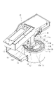
- FIG. 1 is a perspective view showing a wafer chuck mechanism and a cleaning device shown as an example according to an embodiment of the present invention
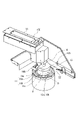
- FIG. FIG. 2 is a perspective view of the wafer chuck mechanism and the cleaning device as viewed from the front right side of FIG. 1
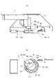
- FIG. 10A is a side view of the suction chuck cleaning grindstone portion and the frame suction holding portion cleaning means, with some of the constituent members omitted, with the arm positioned at the cleaning position
- FIG. ) is a plan view omitting a part of the configuration of (a).
- FIG. 10A is a side view of the suction chuck cleaning grindstone portion and the frame suction holding portion cleaning means, with some of the components omitted, in a state where the arm is placed at the standby position; ) is a plan view omitting a part of the configuration of (a).
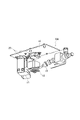
- FIG. 2 is an enlarged view of the essential configuration of the frame suction holding portion cleaning means in the same cleaning apparatus as viewed from the AA direction of FIG. 1;
- FIG. 2 is a perspective view showing a configuration of a main part of a frame suction holding portion cleaning means in the same cleaning apparatus;
- FIG. 4 is a plan view showing an example of a wafer held by a ring frame via an adhesive film;
- a rotating wafer having a wafer suction chuck portion that suction-holds a wafer attached to a ring frame via an adhesive film, and an annular frame suction-holding portion that suction-holds the ring frame outside the wafer suction chuck portion.
- a cleaning apparatus for an adsorption chuck mechanism comprising: frame adsorption holding part cleaning means for cleaning the frame adsorption holding part, the frame adsorption holding part cleaning means being movable above the frame adsorption holding part; It is realized by a configuration comprising at least one of a scraper and a brush that can come into contact with the holding portion, and a water nozzle that discharges water onto the frame suction holding portion.
- drawings may exaggerate by enlarging and exaggerating characteristic parts in order to make the features easier to understand, and the dimensional ratios, etc. of the constituent elements may not necessarily be the same as the actual ones.
- hatching of some components may be omitted in order to facilitate understanding of the cross-sectional structure of the components.
- the cleaning device 10 removes sludge adhering to the chuck mechanism 11, and includes an adsorption chuck cleaning grindstone section 10A, a frame adsorption holding section cleaning means 10B, and a position moving means 10C.
- the chuck mechanism 11 includes a wafer suction chuck portion 11A and a frame suction holding portion 11B surrounding the wafer suction chuck portion 11A.
- the wafer suction chuck portion 11A and the frame suction holding portion 11B integrally rotate in the direction of arrow D in FIG.
- a wafer W is attached to the chuck mechanism 11 during the grinding process.
- a wafer W held by a ring frame 102 via an adhesive film 101 as shown in FIG. 7 is used.
- the wafer W is sucked and held together with the adhesive film 101 on the chuck surface 11a of the wafer chuck portion 11A, and the ring frame 102 is sucked and held by the frame sucking and holding portion 11B.
- the wafer chuck portion 11A and the frame chuck portion 11B are independent from each other, and the wafer chuck portion 11A and the frame chuck portion 11B are vertically movable relative to each other.
- the wafer suction chuck portion 11A moves upward while the frame suction holding portion 11B suction-holds the ring frame 102, the entire adhesive film 101 is stretched, and the wafer W is moved from above the adhesive film 101. Make it easier to remove.
- the chucking surface 11a of the wafer suction chuck portion 11A is made of a porous material, and the wafer W attached to the adhesive film 101 on the chucking surface 11a can be vacuumed and held by suction.
- cleaning water pure water
- the frame suction holding portion 11B evacuates the ring frame 102 placed on the frame suction holding portion 11B, and has a plurality of suction holes 12a for sucking and holding the ring frame 102 on the frame suction holding portion 11B.
- a plurality of water ejection holes 12b for ejecting cleaning water (pure water) from the upper surface of the frame suction holding portion 11B during cleaning of the portion 11B are arranged in rows in the circumferential direction at approximately equal intervals.
- the suction hole 12a and the water discharge hole 12b are shared as the same hole, but they may be provided separately.
- a piping line for vacuuming at the frame suction holding portion 11B and a piping line for vacuuming at the chuck surface 11a of the wafer suction chuck portion 11A are separate systems. Therefore, evacuation can be controlled for each system.
- the position moving means 10C of the cleaning device 10 integrally moves the suction chuck cleaning grindstone portion 10A and the frame suction holding portion cleaning means 10B to the cleaning position and the standby position.
- the position moving means 10C is a rail member that horizontally guides the movement of the suction chuck cleaning grindstone portion 10A and the frame suction holding portion cleaning means 10B between the cleaning position and the standby position along one side of the wafer suction chuck portion 11A. 13 and an arm 14 for holding the suction chuck cleaning grindstone portion 10A. That is, the movement between the cleaning position and the standby position in the suction chuck cleaning grindstone portion 10A and the frame suction holding portion cleaning means 10B is guided by the arm 14 and the rail member 13 .
- the rail member 13 is attached to the base member 21 .
- the base member 21 is also provided with a drying prevention nozzle 22 that supplies water to the frame suction holding portion 11B to prevent drying during standby.
- the suction chuck cleaning grindstone section 10A has a dressing grindstone 15 attached to the lower end of the arm 14 so as to be horizontally rotatable.
- the dressing grindstone 15 is rotated in the direction of arrow E in FIG. 2 by the driving force of a motor (not shown).
- the dressing grindstone 15, while rotating horizontally, is pushed against the chuck surface 11a of the wafer suction chuck portion 11A, which is also rotating, due to the vertical movement of the arm 14, and adheres to the chuck surface 11a. scrape off any sludge.
- water is discharged from the lower surface of the dressing grindstone 15 to raise and scrape off the sludge on the chuck surface 11a.
- the frame suction holding portion cleaning means 10B is attached in a unitized state to a brim-like member 14a fixedly attached to the lower end of the arm 14 adjacent to the upper surface of the dressing grindstone 15. That is, the frame suction holding portion cleaning means 10B has a unit base 16 detachably attached to the flange member 14a. , a scraper 17, a brush 18 and a water nozzle 19 are attached to form a unit. Further, the frame suction holding portion cleaning means 10B unitized by the unit base 16 is detachably attached to the brim-shaped member 14a with bolts, nuts, etc., in a unit state.
- the frame suction/holding portion cleaning means 10B is moved to the cleaning position by the position moving means 10C.
- a water nozzle 19, a brush 18, and a scraper 17 are arranged in order from the upstream side to the downstream side of the direction.
- the contact force (pressing force) with which the brush 18 and the scraper 17 contact the frame suction holding portion 11B is substantially constant.
- a spring mechanism 20 is provided for damping.
- the brush 18 is obliquely attached to the frame suction holding portion 11B so as to remove sludge adhering to the corner portion 23a of the pedestal 23 of the frame suction holding portion 11B.
- the operation of the cleaning device 10 is controlled by control means (not shown).
- the control means controls each component constituting the cleaning apparatus 10 .
- the control means is, for example, a computer, and is composed of a CPU, a memory, and the like.
- the function of the control means may be realized by controlling using software, or may be realized by operating using hardware.
- the grinding apparatus is grinding the wafer W
- the suction chuck cleaning grindstone section 10A and the frame suction holding section cleaning means 10B are moved to the standby positions shown in FIG. 4 by the position moving means 10C.
- the wafer suction chuck portion 11A and the frame suction holding portion 11B rotate.
- the position moving means 10C moves the arm 14 to the cleaning position.
- the suction chuck cleaning grindstone portion 10A and the frame suction holding portion cleaning means 10B are also moved together to the upper position of the cleaning position.
- the wafer suction chuck portion 11A and the frame suction holding portion 11B are each rotated at a predetermined speed. Further, in order to prevent the sludge adhering to the chuck surface 11a of the wafer chuck portion 11A and the frame chuck portion 11B from drying, the wafer chuck portion 11A sprays water from the chuck surface 11a to prevent the frame chuck portion 11A from drying out. In 11B, the water from the water discharge hole 12b and the water from the anti-drying nozzle 22 are received and prevented.
- the rotating dressing grindstone 15 is pressed (contacted) against the chuck surface 11a of the wafer suction chuck section 11A to clean the sludge adhering to the chuck surface 11a. conduct.
- cleaning water is discharged and supplied from the grindstone surface of the dressing grindstone 15 and the entire surface of the chuck surface 11a for cleaning, and the cleaning water after cleaning is discharged to the outside of the chuck surface 11a.
- the frame suction/holding portion cleaning means 10B washing water is discharged and supplied from the water nozzle 19 onto the frame suction/holding portion 11B, and the scraper 17 and the brush 18 are brought into contact with the rotating frame suction/holding portion 11B. Then, the sludge adhering to the frame suction holding portion 11B is washed.
- this sludge cleaning process of the frame suction holding portion 11B water is discharged from a plurality of water discharge holes 12b provided in the frame suction holding portion 11B to wet the entire frame suction holding portion 11B. Since water is discharged from 19 and hit by brush 18, the sludge is likely to float and is scraped off by scraper 17, so scraping is smoothly performed. As a result, the cleaning process of the chuck surface 11a of the wafer adsorption chuck part 11A and the cleaning process of the frame adsorption holding part 11B can be performed at the same time.
- the cleaning water is supplied from the water nozzle 19, the cleaning water is supplied from the dressing grindstone 15, and the chuck is cleaned.
- the supply of washing water from the surface 11a is stopped.
- the rotation of the dressing grindstone 15 also stops, the arm 14 rises, and the dressing grindstone 15 also separates from the chuck surface 11a.
- the suction chuck cleaning grindstone section 10A and the frame suction holding section cleaning means 10B are moved to the standby position shown in FIG. 4 by the position moving means 10C.
- the cleaning of the wafer suction chuck portion 11A and the cleaning of the frame suction holding portion 11B can be performed at the same time. It becomes possible to automatically perform the cleaning process of the suction holding portion 11B.
- the frame suction holding portion 11B is provided with a plurality of water discharge holes 12b for discharging water in the circumferential direction of the frame suction holding portion 11B, it is possible to clean the frame suction holding portion 11B. Water is discharged from the water discharge hole 12b to wet the entire frame suction holding portion 11B, and further water is discharged from the water nozzle 19 to hit the brush 18, so that the sludge is more likely to float, and the scraper 17 removes the sludge. , so that the cleaning treatment effect is improved.
- the wafer suction chuck portion 11A is provided with a water discharge hole for discharging water from the entire chuck surface 11a during cleaning of the wafer suction chuck portion 11A, the wafer suction chuck portion 11A is cleaned during cleaning. Water is discharged from the entire chuck surface 11a of 11A, and the dressing grindstone 15 can be brought into contact with the entire wafer suction chuck portion in a wet state. The sludge scraped off by the dressing grindstone 15 can be easily discharged to the outside of the wafer suction chuck portion 11A.
- the frame suction holding portion cleaning means 10B is provided with a spring mechanism 20 for cushioning the scraper 17 and the brush 18 against the frame suction holding portion 11B, the scraper 17 and the brush 18 come into contact with the frame suction holding portion 11B.
- the contacting force (pressing force) is buffered by the spring action of the spring mechanism 20 to be substantially constant, and the scraper 17 and the brush 18 can be brought into contact with the frame suction holding portion 11B with a constant force.
- the spring mechanism 20 may have a structure in which only one spring mechanism 20 is provided in common for the scraper 17 and the brush 18, or a structure in which the spring mechanism 20 for the scraper 17 and the spring mechanism 20 for the brush 18 are provided individually. . In the case of discrete structures, finer damping adjustments can be made.
- a drying prevention nozzle (keep wet nozzle) 22 is provided to intermittently supply water onto the frame suction holding portion 11B when the cleaning device 10 is on standby, and the frame is suctioned from the drying prevention nozzle 22 when the cleaning device 10 is on standby. Since water is intermittently supplied onto the holding portion 11B, sludge can be prevented from adhering to the frame suction holding portion 11B due to drying.
- the brush 18 when removing the sludge from the frame suction holding portion 11B, the brush 18 is moved while the water nozzle 19 is discharging water onto the frame suction holding portion 11B while the wafer suction chuck portion 11A is being rotated.
- the sludge may be removed by contacting either the brush 18 or the scraper 17.
- the present invention can be modified in various ways without departing from the spirit of the invention, and the present invention naturally extends to such modifications.
Landscapes
- Mechanical Treatment Of Semiconductor (AREA)
- Cleaning Or Drying Semiconductors (AREA)
- Cleaning In General (AREA)
- Cleaning By Liquid Or Steam (AREA)
Abstract
Description
また、フレーム吸着保持部におけるスラッジの除去は、ウエハチャック機構を回転させた状態において、フレーム吸着保持部上にフレーム吸着保持部洗浄手段を配置し、水ノズルからフレーム吸着保持部上に水を吐出しながらブラシ及びスクレーパーの何れか1つを当てると、水でスラッジが浮き、ブラシ及びスクレーパーの何れか又はそれらの両方によりスラッジが掻き取られる。更に掻き取ったスラッジを、水ノズルから吐出された水でフレーム吸着保持部外に流して排出するので、フレーム吸着保持部上のスラッジを簡単、かつ、きれいに除去することができる。
また、本発明は、本発明の精神を逸脱しない限り種々の改変を成すことができ、そして、本発明が該改変されたものに及ぶことは当然である。
10A :吸着チャック洗浄砥石部
10B :フレーム吸着保持部洗浄手段
10C :位置移動手段
11 :チャック機構
11A :ウエハ吸着チャック部
11B :フレーム吸着保持部
11a :チャック面
12a :吸着孔
12b :水吐出孔
13 :レール部材
14 :アーム
14a :鍔状部材
15 :ドレス砥石
16 :ユニットベース
17 :スクレーパー
18 :ブラシ
19 :水ノズル
20 :バネ機構
21 :ベース部材
22 :乾燥防止用ノズル
23 :台座
23a :箇所
101 :粘着フィルム
102 :リングフレーム
W :ウエハ
Claims (5)
- 粘着フィルムを介してリングフレームに取り付けられたウエハを吸着保持するウエハ吸着チャック部と、前記ウエハ吸着チャック部の外側で前記リングフレームを吸着保持する環状のフレーム吸着保持部と、を有する回転するウエハ吸着チャック機構の洗浄装置であって、
前記フレーム吸着保持部上に移動可能で、前記フレーム吸着保持部を洗浄するフレーム吸着保持部洗浄手段を備え、
前記フレーム吸着保持部洗浄手段は、前記フレーム吸着保持部上に接触可能なスクレーパー及びブラシの少なくとも何れか1つと、前記フレーム吸着保持部上に水を吐出する水ノズルとを備える、
ことを特徴とするウエハ吸着チャック機構の洗浄装置。 - 前記ウエハ吸着チャック部上に移動可能に構成され、前記ウエハ吸着チャック部を洗浄する吸着チャック洗浄砥石部を更に備え、
前記フレーム吸着保持部洗浄手段は、前記吸着チャック洗浄砥石部と一体で移動可能に構成されている、ことを特徴とする請求項1に記載のウエハ吸着チャック機構の洗浄装置。 - 前記フレーム吸着保持部は、前記フレーム吸着保持部上に水を吐出する水吐出孔を有する、ことを特徴とする請求項1又は2に記載のウエハ吸着チャック機構の洗浄装置。
- 前記フレーム吸着保持部洗浄手段は、前記スクレーパー又は前記ブラシの前記フレーム吸着保持部への押し当て力を弾性的に吸収するバネ機構を備える、ことを特徴とする請求項1から請求項3までのいずれか1項に記載のウエハ吸着チャック機構の洗浄装置。
- 前記フレーム吸着保持部上に水を間欠的に供給するキープウエットノズルを更に有する、ことを特徴とする請求項1から請求項4までのいずれか1項に記載のウエハ吸着チャック機構の洗浄装置。
Priority Applications (3)
| Application Number | Priority Date | Filing Date | Title |
|---|---|---|---|
| CN202180096323.3A CN117121164A (zh) | 2021-03-26 | 2021-12-14 | 晶圆吸附卡盘机构的清洗装置 |
| KR1020237032362A KR102878592B1 (ko) | 2021-03-26 | 2021-12-14 | 웨이퍼 흡착 척 기구의 세정 장치 |
| US18/283,167 US20250065377A1 (en) | 2021-03-26 | 2021-12-14 | Cleaning device for wafer-suction chuck mechanism |
Applications Claiming Priority (2)
| Application Number | Priority Date | Filing Date | Title |
|---|---|---|---|
| JP2021-054214 | 2021-03-26 | ||
| JP2021054214A JP7721298B2 (ja) | 2021-03-26 | 2021-03-26 | ウエハ吸着チャック機構の洗浄装置 |
Publications (1)
| Publication Number | Publication Date |
|---|---|
| WO2022201665A1 true WO2022201665A1 (ja) | 2022-09-29 |
Family
ID=83396578
Family Applications (1)
| Application Number | Title | Priority Date | Filing Date |
|---|---|---|---|
| PCT/JP2021/045924 Ceased WO2022201665A1 (ja) | 2021-03-26 | 2021-12-14 | ウエハ吸着チャック機構の洗浄装置 |
Country Status (5)
| Country | Link |
|---|---|
| US (1) | US20250065377A1 (ja) |
| JP (1) | JP7721298B2 (ja) |
| KR (1) | KR102878592B1 (ja) |
| CN (1) | CN117121164A (ja) |
| WO (1) | WO2022201665A1 (ja) |
Citations (4)
| Publication number | Priority date | Publication date | Assignee | Title |
|---|---|---|---|---|
| JPH1145866A (ja) * | 1997-07-25 | 1999-02-16 | Sharp Corp | 半導体ウエハの研削装置 |
| JP2005051094A (ja) * | 2003-07-30 | 2005-02-24 | Disco Abrasive Syst Ltd | 切削装置 |
| JP2010021464A (ja) * | 2008-07-14 | 2010-01-28 | Disco Abrasive Syst Ltd | 加工装置のチャックテーブル |
| JP2017073457A (ja) * | 2015-10-07 | 2017-04-13 | 株式会社ディスコ | 洗浄装置 |
Family Cites Families (3)
| Publication number | Priority date | Publication date | Assignee | Title |
|---|---|---|---|---|
| JP2010137349A (ja) | 2008-12-15 | 2010-06-24 | Tokyo Seimitsu Co Ltd | ウェーハ用チャックテーブルおよびウェーハ処理装置 |
| JP7353042B2 (ja) * | 2019-02-25 | 2023-09-29 | 株式会社東京精密 | ブラシ洗浄装置 |
| KR20200107565A (ko) * | 2019-03-08 | 2020-09-16 | 에스케이실트론 주식회사 | 웨이퍼 폴리싱 장치 |
-
2021
- 2021-03-26 JP JP2021054214A patent/JP7721298B2/ja active Active
- 2021-12-14 WO PCT/JP2021/045924 patent/WO2022201665A1/ja not_active Ceased
- 2021-12-14 KR KR1020237032362A patent/KR102878592B1/ko active Active
- 2021-12-14 US US18/283,167 patent/US20250065377A1/en active Pending
- 2021-12-14 CN CN202180096323.3A patent/CN117121164A/zh active Pending
Patent Citations (4)
| Publication number | Priority date | Publication date | Assignee | Title |
|---|---|---|---|---|
| JPH1145866A (ja) * | 1997-07-25 | 1999-02-16 | Sharp Corp | 半導体ウエハの研削装置 |
| JP2005051094A (ja) * | 2003-07-30 | 2005-02-24 | Disco Abrasive Syst Ltd | 切削装置 |
| JP2010021464A (ja) * | 2008-07-14 | 2010-01-28 | Disco Abrasive Syst Ltd | 加工装置のチャックテーブル |
| JP2017073457A (ja) * | 2015-10-07 | 2017-04-13 | 株式会社ディスコ | 洗浄装置 |
Also Published As
| Publication number | Publication date |
|---|---|
| JP2022151236A (ja) | 2022-10-07 |
| KR102878592B1 (ko) | 2025-10-29 |
| JP7721298B2 (ja) | 2025-08-12 |
| KR20230148353A (ko) | 2023-10-24 |
| US20250065377A1 (en) | 2025-02-27 |
| CN117121164A (zh) | 2023-11-24 |
Similar Documents
| Publication | Publication Date | Title |
|---|---|---|
| KR102182910B1 (ko) | 웨이퍼의 엣지 연마 장치 및 방법 | |
| JP6054805B2 (ja) | 基板洗浄装置 | |
| TWI855112B (zh) | 邊緣修整裝置 | |
| JP5325003B2 (ja) | 研削装置 | |
| JP2003151943A (ja) | スクラブ洗浄装置 | |
| JP2018111146A (ja) | 基板処理システムおよび基板処理方法 | |
| JP2019063885A (ja) | 加工装置 | |
| CN217728158U (zh) | 双面研磨装置 | |
| JP2021074825A (ja) | 保持面洗浄装置 | |
| JP2010087443A (ja) | 搬送機構 | |
| JP5932320B2 (ja) | 研削装置 | |
| JP6468037B2 (ja) | 研磨装置 | |
| TWI824755B (zh) | 一種用於承載和清潔矽片的裝置 | |
| JP2007194367A (ja) | 洗浄装置及び該洗浄装置を備えるダイシング装置 | |
| JP2017147334A (ja) | 基板の裏面を洗浄する装置および方法 | |
| WO2022201665A1 (ja) | ウエハ吸着チャック機構の洗浄装置 | |
| JP5894490B2 (ja) | 研削装置 | |
| US5897425A (en) | Vertical polishing tool and method | |
| JP2019186497A (ja) | 洗浄装置 | |
| JP7161412B2 (ja) | 洗浄ユニット | |
| JP2008098574A (ja) | ウエーハの研磨装置 | |
| JP2023018185A (ja) | 洗浄装置 | |
| JP2005152817A (ja) | 洗浄装置及び半導体装置の製造装置 | |
| JP7578399B2 (ja) | 加工装置及び連通管の洗浄方法 | |
| JP7161411B2 (ja) | 乾燥機構 |
Legal Events
| Date | Code | Title | Description |
|---|---|---|---|
| 121 | Ep: the epo has been informed by wipo that ep was designated in this application |
Ref document number: 21931947 Country of ref document: EP Kind code of ref document: A1 |
|
| ENP | Entry into the national phase |
Ref document number: 20237032362 Country of ref document: KR Kind code of ref document: A |
|
| WWE | Wipo information: entry into national phase |
Ref document number: 1020237032362 Country of ref document: KR |
|
| NENP | Non-entry into the national phase |
Ref country code: DE |
|
| 122 | Ep: pct application non-entry in european phase |
Ref document number: 21931947 Country of ref document: EP Kind code of ref document: A1 |
|
| WWP | Wipo information: published in national office |
Ref document number: 18283167 Country of ref document: US |
|
| WWG | Wipo information: grant in national office |
Ref document number: 1020237032362 Country of ref document: KR |