WO2022185813A1 - ガイドワイヤ - Google Patents
ガイドワイヤ Download PDFInfo
- Publication number
- WO2022185813A1 WO2022185813A1 PCT/JP2022/003746 JP2022003746W WO2022185813A1 WO 2022185813 A1 WO2022185813 A1 WO 2022185813A1 JP 2022003746 W JP2022003746 W JP 2022003746W WO 2022185813 A1 WO2022185813 A1 WO 2022185813A1
- Authority
- WO
- WIPO (PCT)
- Prior art keywords
- guidewire
- coil body
- core shaft
- distal
- resin
- Prior art date
- Legal status (The legal status is an assumption and is not a legal conclusion. Google has not performed a legal analysis and makes no representation as to the accuracy of the status listed.)
- Ceased
Links
Images


Classifications
-
- A—HUMAN NECESSITIES
- A61—MEDICAL OR VETERINARY SCIENCE; HYGIENE
- A61M—DEVICES FOR INTRODUCING MEDIA INTO, OR ONTO, THE BODY; DEVICES FOR TRANSDUCING BODY MEDIA OR FOR TAKING MEDIA FROM THE BODY; DEVICES FOR PRODUCING OR ENDING SLEEP OR STUPOR
- A61M25/00—Catheters; Hollow probes
- A61M25/01—Introducing, guiding, advancing, emplacing or holding catheters
- A61M25/09—Guide wires
- A61M2025/09058—Basic structures of guide wires
- A61M2025/09083—Basic structures of guide wires having a coil around a core
- A61M2025/09091—Basic structures of guide wires having a coil around a core where a sheath surrounds the coil at the distal part
-
- A—HUMAN NECESSITIES
- A61—MEDICAL OR VETERINARY SCIENCE; HYGIENE
- A61M—DEVICES FOR INTRODUCING MEDIA INTO, OR ONTO, THE BODY; DEVICES FOR TRANSDUCING BODY MEDIA OR FOR TAKING MEDIA FROM THE BODY; DEVICES FOR PRODUCING OR ENDING SLEEP OR STUPOR
- A61M25/00—Catheters; Hollow probes
- A61M25/01—Introducing, guiding, advancing, emplacing or holding catheters
- A61M25/09—Guide wires
- A61M2025/09133—Guide wires having specific material compositions or coatings; Materials with specific mechanical behaviours, e.g. stiffness, strength to transmit torque
-
- A—HUMAN NECESSITIES
- A61—MEDICAL OR VETERINARY SCIENCE; HYGIENE
- A61M—DEVICES FOR INTRODUCING MEDIA INTO, OR ONTO, THE BODY; DEVICES FOR TRANSDUCING BODY MEDIA OR FOR TAKING MEDIA FROM THE BODY; DEVICES FOR PRODUCING OR ENDING SLEEP OR STUPOR
- A61M25/00—Catheters; Hollow probes
- A61M25/01—Introducing, guiding, advancing, emplacing or holding catheters
- A61M25/09—Guide wires
- A61M2025/09175—Guide wires having specific characteristics at the distal tip
-
- A—HUMAN NECESSITIES
- A61—MEDICAL OR VETERINARY SCIENCE; HYGIENE
- A61M—DEVICES FOR INTRODUCING MEDIA INTO, OR ONTO, THE BODY; DEVICES FOR TRANSDUCING BODY MEDIA OR FOR TAKING MEDIA FROM THE BODY; DEVICES FOR PRODUCING OR ENDING SLEEP OR STUPOR
- A61M2205/00—General characteristics of the apparatus
- A61M2205/02—General characteristics of the apparatus characterised by a particular materials
- A61M2205/0216—Materials providing elastic properties, e.g. for facilitating deformation and avoid breaking
Definitions
- the technology disclosed in this specification relates to guidewires.
- a guidewire In general, guidewires and the like that are inserted into the body, such as into blood vessels, are required to have good insertability into blood vessels, etc., and good operability inside blood vessels, etc.
- a guidewire includes, for example, a core shaft, a coil body that covers the outer periphery of the core shaft, and a distal joint that joins the distal end of the coil body and the distal end of the core shaft.
- a guide wire inserted into a blood vessel or the like is required to have a strong connection between the coil body and the core shaft, as well as good insertability and operability.
- the tip of the guidewire may hit the inner wall of the blood vessel at the entrance of the side branch.
- the distal end of the guidewire is less flexible (harder)
- the resistance at the distal end increases when the guidewire is further pushed in, and the guidewire advances toward the distal side of the side branch. It tends to be difficult to let go.
- Such a problem is not limited to advancing the guidewire from the main canal to the side branch, but is also a common problem when advancing the guidewire through a blood vessel having a complicated shape.
- This specification discloses a technology capable of solving the above-described problems.
- the guidewire disclosed in the present specification includes a core shaft, a coil body that covers the outer periphery of the core shaft, and a distal joint that joins the distal end of the coil body and the distal end of the core shaft. and, wherein the distal joint portion is formed of a resin material, joins the coil body and the core shaft on the proximal side of the distal joint portion, and is made of a metal material a fixed portion formed by
- the distal joint is made of a resin material, the slipperiness and flexibility of the distal end can be improved.
- the fixing portion is made of a metal material, the coil body and the core shaft can be firmly joined. Therefore, according to the present guidewire, it is possible to provide a guidewire in which the joint strength between the coil body and the core shaft is ensured while having good flexibility at the distal end portion.
- the distal joint may be made of an elastomer material. According to the guidewire adopting this configuration, the flexibility of the distal end of the guidewire can be further increased, so that it is possible to more reliably prevent damage to the inner wall of the blood vessel, etc., when the guidewire is inserted into the blood vessel, etc. .
- the gap between the distal joint portion and the fixed portion in the axial direction of the guidewire may be smaller than the length of the distal joint portion in the axial direction.
- the gap between the distal joint portion and the fixed portion is relatively small.
- the fixing portion is arranged at a position close to the distal end of the guidewire. Therefore, in the present guidewire, it is possible to more effectively ensure the joint strength between the coil body and the core shaft at the distal end thereof.
- the distal end joint portion and the fixed portion may be arranged continuously in the axial direction of the guidewire.
- the fixing portion is arranged at a position close to the distal end of the guidewire. Therefore, in the present guidewire, it is possible to more effectively ensure the joint strength between the coil body and the core shaft at the distal end thereof.
- the length of the distal end joint portion in the axial direction of the guidewire may be 2 or more times and 10 or less times the outer diameter of the coil body. Therefore, according to the guide wire adopting this configuration, it is possible to more effectively secure the joint strength between the distal joint portion and the coil body.
- the guide wire includes a resin coating that covers the outer surface of the distal joint portion and the outer peripheral surface of the coil body and is formed of one or more resin materials,
- the resin material forming the distal end joint may be at least one of the resin materials forming the resin film. Therefore, according to the guide wire adopting this configuration, it is possible to improve the adhesion between the distal joint portion and the resin coating, thereby preventing the resin coating from peeling off from the distal joint portion. can be done.
- FIG. 2 is an explanatory diagram schematically showing the configuration of a longitudinal section of the guidewire 100 according to the first embodiment; Partially enlarged view of the guide wire 100 Explanatory drawing schematically showing the configuration of a longitudinal section of a guide wire 100A in the second embodiment. Explanatory drawing schematically showing the configuration of a longitudinal section of a guide wire 100B in the third embodiment.
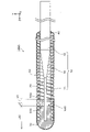
- FIG. 1 is an explanatory diagram schematically showing the configuration of the guidewire 100 in the first embodiment.
- FIG. 1 shows a longitudinal section (YZ section) of the guidewire 100 .
- the Z-axis positive direction side is the tip side (distal side) inserted into the body
- the Z-axis negative direction side is the proximal side (proximal side) operated by an operator such as a doctor. .
- FIG. 1 shows a cross-sectional (specifically, YZ cross-sectional) configuration of a coil body 20, a distal joint portion 30, a proximal joint portion 40, a metal fixing portion 50, and a resin portion 60, which will be described later.
- FIG. 1 shows the guide wire 100 as a whole in a straight line substantially parallel to the Z-axis direction, the guide wire 100 has flexibility to the extent that it can be curved.
- a portion of the guide wire 100 and each constituent member of the guide wire 100 including the distal end and extending from the distal end toward the base end halfway is referred to as a "distal end”.
- a portion that includes the proximal end and extends halfway toward the distal side from the proximal end is referred to as a "base end”.
- the guide wire 100 is a medical device that is inserted into a blood vessel or the like, for example, to guide a catheter (not shown) to a lesion (stenosis or occlusion) in the blood vessel or the like.
- the guidewire 100 includes a core shaft 10, a coil body 20, a distal joint portion 30, a proximal joint portion 40, a metal fixing portion 50, and a resin portion 60.
- the metal fixing portion 50 is an example of a fixing portion in the scope of claims.
- the core shaft 10 is an elongated member with a small diameter on the distal end side and a large diameter on the proximal end side.
- the core shaft 10 has a small diameter portion 11 , a large diameter portion 12 and a tapered portion 13 .
- illustration of a part of the large-diameter portion 12 is omitted.
- the small diameter portion 11 is a portion including the tip of the core shaft 10 .
- the small diameter portion 11 has a rod shape with a circular cross section.
- the cross section is a section (XY section in this embodiment) orthogonal to the axial direction (Z-axis direction in this embodiment) of the core shaft 10 (the same applies to the second embodiment and thereafter).
- the axial direction of the core shaft 10 coincides with the axial direction of the guide wire 100 .
- the large-diameter portion 12 is located on the base end side of the core shaft 10 with respect to the small-diameter portion 11 , and has a circular cross-section with a larger outer diameter than the small-diameter portion 11 .
- Tapered portion 13 is located between small diameter portion 11 and large diameter portion 12 .
- the tapered portion 13 has an outer diameter that gradually increases from the boundary position with the small diameter portion 11 toward the boundary position with the large diameter portion 12 .
- the outer diameter of the small diameter portion 11 is, for example, about 0.03 mm to 0.085 mm, and the outer diameter of the large diameter portion 12 is, for example, about 0.2 to 0.9 mm.
- the cross-sectional shape of each part of the core shaft 10 is not particularly limited, and may be polygonal such as triangular or quadrangular, for example.
- the core shaft 10 As a material for forming the core shaft 10, known materials are used. Wires, nickel-chromium alloys, cobalt alloys, tungsten, etc. are used.
- the core shaft 10 may be made of the same material as a whole, or may be made of different materials for each part.
- the coil body 20 is a coil-shaped member formed into a hollow cylindrical shape by spirally winding one wire.
- the coil body 20 is arranged so as to surround the outer circumference of the distal end portion of the core shaft 10 (specifically, the small diameter portion 11, the tapered portion 13, and part of the large diameter portion 12).
- a bore H is formed between the core shaft 10 and the coil body 20 .
- the total length of the coil body 20 is, for example, approximately 10 mm to 500 mm, and the outer diameter D20 (see FIG. 2) of the coil body 20 is, for example, approximately 0.2 mm to 0.9 mm.
- the coil body 20 As a material for forming the coil body 20, known materials are used. Wires, nickel-chromium alloys, cobalt alloys, tungsten, etc. are used.
- the distal joint 30 joins the distal end of the core shaft 10 and the distal end of the coil body 20 .
- the distal end of the core shaft 10 and the distal end of the coil body 20 are embedded and fixed inside the distal joint portion 30 .
- An outer peripheral surface on the distal end side of the distal joint portion 30 is a smooth surface (for example, a substantially hemispherical surface and a cylindrical surface).
- the distal joint 30 preferably has elasticity and flexibility, and is made of a resin material.
- a resin material for example, an elastomer material such as a thermosetting elastomer resin or a thermoplastic elastomer resin is used.
- thermosetting elastomer resin for example, silicone rubber, fluororubber, or the like is used.
- thermoplastic elastomer for example, polyurethane-based resin, polyester-based resin, polyamide-based resin, or the like is used.
- the distal joint portion 30 more preferably contains at least one of the resin materials that form the resin portion 60 described later.
- a resin for example, a hydrophilic resin or the like can be used, and more preferably a polyurethane resin or the like is used.
- the distal joint portion 30 may be made of one kind of resin material, or may be made of two or more kinds of resin materials. Arranging the flexible distal joint 30 on the distal side with respect to the core shaft 10 prevents damage to the blood vessel wall. Moreover, the presence of the resin portion 60 can improve the slipperiness of the distal end portion of the guide wire 100 . A detailed configuration of the distal joint portion 30 will be described later.
- the base end joint portion 40 is a member that joins the base end side of the core shaft 10 and the base end side of the coil body 20 .
- Known materials are used as materials for forming the base end joint portion 40.
- brazing materials aluminum alloy brazing, silver brazing, gold brazing, etc.
- metal solders Al--Sn alloys, Au--Sn alloys, etc.
- adhesives epoxy-based adhesives, etc.
- brazing material is used as the material forming the base end joint portion 40 .
- the metal fixing part 50 is a member that joins the coil body 20 and the core shaft 10 on the base end side of the distal joint part 30 .
- a portion of the core shaft 10 and a portion of the coil body 20 are embedded in the metal fixing portion 50 and joined together. More specifically, in this embodiment, as shown in the partial enlarged view of FIG. It is formed so as to cover the outer surface with a substantially constant thickness.
- materials for forming the metal fixing portion 50 include metal solder (Au—Sn alloy, Sn—Ag alloy, Sn—Pb alloy, Pb—Ag alloy, etc.), brazing material (aluminum alloy brazing, silver brazing, gold brazing, etc.). etc.) are used.
- the materials forming the metal fixing portion 50 and the proximal joint portion 40 may be the same or different. A detailed configuration of the metal fixing portion 50 will be described later.
- the resin portion 60 is a coating member made of one or more resin materials and covering the outer peripheral surface of the coil body 20 and the outer surfaces of the distal joint portion 30 and the proximal joint portion 40 .
- a known material such as a silicone resin is used.
- the resin material forming the resin portion 60 is preferably a hydrophilic resin, more preferably a hyaluronic acid-based resin, a PVA resin, or the like.
- the thickness of the resin portion 60 is, for example, approximately 0.002 to 0.1 mm.
- the resin portion 60 is an example of a resin coating in the claims.
- FIG. 2 is an explanatory diagram showing the configurations of the distal joint portion 30 and the metal fixing portion 50, and shows an enlarged longitudinal section (YZ section) thereof.
- the distal joint portion 30 has a fixing portion 31 and a distal end portion 33 .
- the fixing portion 31 is located on the most proximal side of the distal joint portion 30 and is a portion that fixes the distal end portion of the coil body 20 and the distal end portion of the core shaft 10 .
- the distal end portion 33 is provided at the distal end of the fixed portion 31 in the distal joint portion 30, and is a substantially spherical portion having an outer diameter that decreases toward the distal direction.
- the outer diameter of the distal end of the fixing portion 31 and the outer diameter of the proximal end of the distal end portion 33 are the same. That is, the outer surface of the fixed portion 31 and the outer surface of the distal end portion 33 are continuous. Further, in the present embodiment, the shape of the cross section (XY section) of the fixing portion 31 and the distal end portion 33 is substantially circular.
- the length L30 of the tip side joint portion 30 in the Z-axis direction is, for example, about 0.5 mm to 5 mm.
- the length L30 of the distal joint portion 30 can be, for example, about twice or more and about ten times or less, more specifically about three times the outer diameter D20 of the coil body 20 .
- the length L33 of the distal end portion 33 is, for example, approximately 0.45 mm to 1 mm. In this embodiment, the length L30 of the distal joint 30 is approximately 4 mm.
- the length L50 of the metal fixing portion 50 in the Z-axis direction is, for example, about 0.5 mm to 1.5 mm from the viewpoint of securing the joint strength between the coil body 20 and the core shaft 10. More specifically, , about 0.5 mm to 1 mm.
- the metal fixing portion 50 is positioned, for example, within 5 mm from the distal end of the guidewire 100 from the viewpoint of securing the bonding strength between the coil body 20 and the core shaft 10 at the distal end of the guidewire 100 .
- the end surface S30 on the proximal side of the distal joint portion 30 (specifically, the fixing portion 31) and the end surface S50 on the distal side of the metal fixing portion 50 are entirely are in contact with each other.
- the distal joint portion 30 and the metal fixing portion 50 are arranged continuously in the Z-axis direction. 1 and 2
- the end surface S30 of the tip-side joint portion 30 and the end surface S50 of the metal fixing portion 50 are drawn as surfaces perpendicular to the Z-axis direction, but the present invention is limited to this. not. The same applies to subsequent figures.
- the guidewire 100 of this embodiment can be manufactured, for example, by the following method. First, the core shaft 10 whose shape is processed by mechanical polishing or the like, and the coil body 20 manufactured by winding the coil wire are prepared. The core shaft 10 is inserted into the hollow portion of the coil body 20, and a distal joint portion 30, a proximal joint portion 40, and a metal fixing portion 50 for joining the coil body 20 and the core shaft 10 are formed.
- the tip joint 30 is formed by, for example, injecting molten resin into a mold capable of forming the shape of the tip joint 30, and immersing the tip portions of the core shaft 10 and the coil body 20 therein. It is formed by cooling.
- the metal fixing portion 50 is formed by injecting molten brazing material from the gap of the coil body 20 at the position where the metal fixing portion 50 is to be formed and cooling it.
- the proximal joint portion 40 is formed by brazing the core shaft 10 on the proximal side of the coil body 20 .
- the resin portion 60 is formed by dipping in the molten resin forming the resin portion 60 .
- the guide wire 100 having the configuration described above can be manufactured by the method described above.
- the guidewire 100 of this embodiment includes the core shaft 10 , the coil body 20 , and the distal joint 30 .
- the tip-side joint portion 30 is made of a resin material.
- Guidewire 100 further comprises a metal anchor 50 .
- the metal fixing portion 50 joins the coil body 20 and the core shaft 10 on the base end side of the distal joint portion 30 and is made of a metal material.
- the distal joint portion 30 is made of a resin material, the slipperiness and flexibility of the distal portion can be improved.
- the metal fixing portion 50 is made of a metal material, so that the coil body 20 and the core shaft 10 can be firmly joined. Therefore, according to the guidewire 100 of the present embodiment, it is possible to provide the guidewire 100 in which the joint strength between the coil body 20 and the core shaft 10 is ensured while having good flexibility at the distal end portion. .
- the distal joint portion 30 is made of an elastomer material. According to the guidewire 100 of the present embodiment, the flexibility of the distal end portion of the guidewire 100 can be further enhanced, so that it is possible to more reliably prevent damage to the inner wall of the blood vessel or the like when the guidewire 100 is inserted into the blood vessel or the like. .
- the distal joint portion 30 and the metal fixing portion 50 are arranged continuously in the axial direction of the guidewire 100 .
- the metal fixing portion 50 is arranged at a position close to the distal end of the guidewire 100 . Therefore, in the guidewire 100 of the present embodiment, the joint strength between the coil body 20 and the core shaft 10 can be more effectively secured at the distal end thereof.
- the length of the distal joint portion 30 in the axial direction of the guidewire 100 is two times or more and ten times or less the outer diameter D20 of the coil body 20 . Therefore, according to the guidewire 100 of the present embodiment, the joint strength between the distal joint portion 30 and the coil body 20 can be secured more effectively.
- the guide wire 100 of the present embodiment further includes the resin portion 60 , and the resin material forming the distal joint portion 30 is at least one kind of resin material forming the resin portion 60 . Therefore, according to the guide wire 100 of the present embodiment, it is possible to improve the adhesion between the distal joint portion 30 and the resin portion 60 , thereby preventing the resin portion 60 from being separated from the distal joint portion 30 . can be prevented.
- FIG. 3 is an explanatory diagram schematically showing the configuration of a longitudinal section (YZ section) of the guidewire 100A in the second embodiment.
- YZ section longitudinal section
- the guidewire 100A of the second embodiment has a metal fixing portion 50A instead of the metal fixing portion 50 of the guidewire 100 of the first embodiment.
- the metal fixing portion 50A like the metal fixing portion 50, is a member that joins the coil body 20 and the core shaft 10 on the base end side of the distal joint portion 30, and is made of the metal material described above.
- the metal fixing portion 50A is arranged apart from the distal joint portion 30 . In other words, the end surface S30 of the tip-side joint portion 30 and the end surface S50 of the metal fixing portion 50A are not in contact with each other over the entirety.
- the gap Ld between the distal joint portion 30 and the metal fixing portion 50A is smaller than the length L30 of the distal joint portion 30, for example, about 0.5 mm to 1 mm.
- the length L50 of the metal fixing portion 50A is the same as the length L50 of the metal fixing portion 50, and is, for example, about 0.5 mm to 1.5 mm, more specifically about 0.5 mm to 1 mm. is.
- the metal fixing portion 50A is positioned, for example, within 5 mm from the distal end of the guidewire 100 from the viewpoint of ensuring the bonding strength between the coil body 20 and the core shaft 10 at the distal end of the guidewire 100. As shown in FIG.
- the gap Ld between the distal joint portion 30 and the metal fixing portion 50A in the axial direction of the guidewire 100A is smaller than the length L30 of the distal joint portion 30 in the axial direction.
- the gap Ld between the distal joint portion 30 and the metal fixing portion 50A is relatively small.
- the metal fixing portion 50A is arranged at a position close to the distal end of the guidewire 100A. Therefore, in the guidewire 100A of the present embodiment, it is possible to more effectively secure the joint strength between the coil body 20 and the core shaft 10 at the distal end thereof.
- FIG. 4 is an explanatory view schematically showing the configuration of a longitudinal section (YZ section) of the guidewire 100B in the third embodiment.
- the same reference numerals are assigned to the same configurations as those of the guidewire 100 of the first embodiment, and the description thereof will be omitted as appropriate.
- the guidewire 100B of the third embodiment does not include the resin portion 60 of the guidewire 100 of the first embodiment. According to the guide wire 100B of the present embodiment, the effects of the guide wire 100 of the first embodiment except for the effect of providing the resin portion 60 are exhibited.
- the configuration in which the outer surface of the coil body 20 is embedded in the metal fixing portion 50 is adopted in the first embodiment, the configuration is not limited to this. That is, a part of the outer surface of the coil body 20 is not embedded in the metal fixing part 50, and the outer surface of the coil body 20 is in contact with the resin part 60 at the part where the metal fixing part 50 is arranged. good too.
- the outer surface of the coil body 20 may be exposed.
- the end surface S30 of the distal joint portion 30 and the end surface S50 of the metal fixing portion 50 are in contact with each other over the entire area, but the configuration is not limited to this. That is, the end surface S30 and the end surface S50 may be configured so as not to be in contact with each other at least partially.
- the gap Ld between the tip side joint portion 30 and the metal fixing portion 50 may be equal to or longer than the length L30 of the tip side joint portion 30 .
- the length L30 of the distal joint 30 may be less than twice the outer diameter D20 of the coil body 20, or more than ten times.
- the resin portion 60 may be configured to cover at least a portion of the outer surfaces of the distal joint portion 30 and the metal fixing portion 50 .
- the distal joint portion 30 may be made of a resin material different from the resin material forming the resin portion 60 .
- each member in the above embodiment is merely an example, and various modifications are possible.
- the method of manufacturing the guidewire in the above embodiment is merely an example, and various modifications are possible.
- the metal fixing portion 50 is formed after the distal joint portion 30 is formed, but the distal joint portion 30 may be formed after the metal fixing portion 50 is formed.
- the distal end portion 33 of the distal joint portion 30 has a substantially spherical segment shape, but the present invention is not limited to this, and other shapes may be employed.
Landscapes
- Health & Medical Sciences (AREA)
- Life Sciences & Earth Sciences (AREA)
- Biophysics (AREA)
- Pulmonology (AREA)
- Engineering & Computer Science (AREA)
- Anesthesiology (AREA)
- Biomedical Technology (AREA)
- Heart & Thoracic Surgery (AREA)
- Hematology (AREA)
- Animal Behavior & Ethology (AREA)
- General Health & Medical Sciences (AREA)
- Public Health (AREA)
- Veterinary Medicine (AREA)
- Media Introduction/Drainage Providing Device (AREA)
Priority Applications (3)
| Application Number | Priority Date | Filing Date | Title |
|---|---|---|---|
| EP22762871.6A EP4302814A4 (en) | 2021-03-03 | 2022-02-01 | GUIDE WIRE |
| CN202280018062.8A CN116963798A (zh) | 2021-03-03 | 2022-02-01 | 导丝 |
| US18/448,465 US20230381462A1 (en) | 2021-03-03 | 2023-08-11 | Guide wires |
Applications Claiming Priority (2)
| Application Number | Priority Date | Filing Date | Title |
|---|---|---|---|
| JP2021-033173 | 2021-03-03 | ||
| JP2021033173A JP7538743B2 (ja) | 2021-03-03 | 2021-03-03 | ガイドワイヤ |
Related Child Applications (1)
| Application Number | Title | Priority Date | Filing Date |
|---|---|---|---|
| US18/448,465 Continuation US20230381462A1 (en) | 2021-03-03 | 2023-08-11 | Guide wires |
Publications (1)
| Publication Number | Publication Date |
|---|---|
| WO2022185813A1 true WO2022185813A1 (ja) | 2022-09-09 |
Family
ID=83155000
Family Applications (1)
| Application Number | Title | Priority Date | Filing Date |
|---|---|---|---|
| PCT/JP2022/003746 Ceased WO2022185813A1 (ja) | 2021-03-03 | 2022-02-01 | ガイドワイヤ |
Country Status (5)
| Country | Link |
|---|---|
| US (1) | US20230381462A1 (https=) |
| EP (1) | EP4302814A4 (https=) |
| JP (1) | JP7538743B2 (https=) |
| CN (1) | CN116963798A (https=) |
| WO (1) | WO2022185813A1 (https=) |
Citations (6)
| Publication number | Priority date | Publication date | Assignee | Title |
|---|---|---|---|---|
| JPH08238319A (ja) * | 1994-11-29 | 1996-09-17 | Target Therapeutics Inc | 潤滑性の向上したガイドワイヤ |
| JP2010214054A (ja) | 2009-03-19 | 2010-09-30 | Japan Lifeline Co Ltd | 医療用ガイドワイヤ |
| JP2012152478A (ja) * | 2011-01-28 | 2012-08-16 | Asahi Intecc Co Ltd | ガイドワイヤ |
| JP2013111320A (ja) * | 2011-11-30 | 2013-06-10 | Asahi Intecc Co Ltd | ガイドワイヤ |
| WO2013114985A1 (ja) * | 2012-02-01 | 2013-08-08 | 株式会社パイオラックスメディカルデバイス | ガイドワイヤ |
| JP2017080153A (ja) * | 2015-10-29 | 2017-05-18 | 株式会社パイオラックスメディカルデバイス | ガイドワイヤ |
Family Cites Families (3)
| Publication number | Priority date | Publication date | Assignee | Title |
|---|---|---|---|---|
| US5067489A (en) * | 1988-08-16 | 1991-11-26 | Flexmedics Corporation | Flexible guide with safety tip |
| JP2014100300A (ja) * | 2012-11-20 | 2014-06-05 | Asahi Intecc Co Ltd | ガイドワイヤ |
| CN112135655B (zh) * | 2018-05-01 | 2023-06-13 | 朝日英达科株式会社 | 导丝 |
-
2021
- 2021-03-03 JP JP2021033173A patent/JP7538743B2/ja active Active
-
2022
- 2022-02-01 CN CN202280018062.8A patent/CN116963798A/zh active Pending
- 2022-02-01 WO PCT/JP2022/003746 patent/WO2022185813A1/ja not_active Ceased
- 2022-02-01 EP EP22762871.6A patent/EP4302814A4/en active Pending
-
2023
- 2023-08-11 US US18/448,465 patent/US20230381462A1/en active Pending
Patent Citations (6)
| Publication number | Priority date | Publication date | Assignee | Title |
|---|---|---|---|---|
| JPH08238319A (ja) * | 1994-11-29 | 1996-09-17 | Target Therapeutics Inc | 潤滑性の向上したガイドワイヤ |
| JP2010214054A (ja) | 2009-03-19 | 2010-09-30 | Japan Lifeline Co Ltd | 医療用ガイドワイヤ |
| JP2012152478A (ja) * | 2011-01-28 | 2012-08-16 | Asahi Intecc Co Ltd | ガイドワイヤ |
| JP2013111320A (ja) * | 2011-11-30 | 2013-06-10 | Asahi Intecc Co Ltd | ガイドワイヤ |
| WO2013114985A1 (ja) * | 2012-02-01 | 2013-08-08 | 株式会社パイオラックスメディカルデバイス | ガイドワイヤ |
| JP2017080153A (ja) * | 2015-10-29 | 2017-05-18 | 株式会社パイオラックスメディカルデバイス | ガイドワイヤ |
Non-Patent Citations (1)
| Title |
|---|
| See also references of EP4302814A4 |
Also Published As
| Publication number | Publication date |
|---|---|
| US20230381462A1 (en) | 2023-11-30 |
| JP2022134196A (ja) | 2022-09-15 |
| EP4302814A4 (en) | 2025-01-15 |
| JP7538743B2 (ja) | 2024-08-22 |
| EP4302814A1 (en) | 2024-01-10 |
| CN116963798A (zh) | 2023-10-27 |
Similar Documents
| Publication | Publication Date | Title |
|---|---|---|
| JP7339355B2 (ja) | 医療用管状体 | |
| JP7266407B2 (ja) | カテーテル及びカテーテルの製造方法 | |
| US9623212B2 (en) | Guide wire | |
| CN102811759B (zh) | 导丝 | |
| US11890428B2 (en) | Catheter | |
| JP7175311B2 (ja) | ガイドワイヤ及びガイドワイヤを製造する方法 | |
| US20200353210A1 (en) | Catheter | |
| WO2022185813A1 (ja) | ガイドワイヤ | |
| JP6850368B2 (ja) | カテーテル | |
| JP7474589B2 (ja) | ガイドワイヤ、ガイドワイヤの製造方法 | |
| JP2006271901A (ja) | コイル状造影マーカーとその製造方法、及びカテーテル | |
| JP2024037226A (ja) | カテーテル | |
| JP7389123B2 (ja) | ガイドワイヤ | |
| WO2022158366A1 (ja) | 多層コイル | |
| JP7529799B2 (ja) | ガイドワイヤ | |
| US20260076690A1 (en) | Medical device | |
| WO2025142505A1 (ja) | ガイドワイヤ | |
| JP2013138704A (ja) | 医療機器、および医療機器の製造方法 | |
| WO2024038595A1 (ja) | 医療用長尺体およびカテーテル | |
| JP2025101072A (ja) | ガイドワイヤ | |
| JP2025101069A (ja) | ガイドワイヤ | |
| JP2025175317A (ja) | 医療デバイスおよび医療デバイスの製造方法 | |
| WO2025099917A1 (ja) | 医療デバイス | |
| JP2025005471A (ja) | ガイドワイヤ | |
| JP2024049609A (ja) | ガイドワイヤ |
Legal Events
| Date | Code | Title | Description |
|---|---|---|---|
| 121 | Ep: the epo has been informed by wipo that ep was designated in this application |
Ref document number: 22762871 Country of ref document: EP Kind code of ref document: A1 |
|
| WWE | Wipo information: entry into national phase |
Ref document number: 202280018062.8 Country of ref document: CN |
|
| WWE | Wipo information: entry into national phase |
Ref document number: 2022762871 Country of ref document: EP |
|
| NENP | Non-entry into the national phase |
Ref country code: DE |
|
| ENP | Entry into the national phase |
Ref document number: 2022762871 Country of ref document: EP Effective date: 20231004 |