WO2022185613A1 - 樹脂成形品の製造装置、樹脂成形品の製造方法および金型 - Google Patents
樹脂成形品の製造装置、樹脂成形品の製造方法および金型 Download PDFInfo
- Publication number
- WO2022185613A1 WO2022185613A1 PCT/JP2021/040303 JP2021040303W WO2022185613A1 WO 2022185613 A1 WO2022185613 A1 WO 2022185613A1 JP 2021040303 W JP2021040303 W JP 2021040303W WO 2022185613 A1 WO2022185613 A1 WO 2022185613A1
- Authority
- WO
- WIPO (PCT)
- Prior art keywords
- mold
- molded product
- heater
- resin molded
- manufacturing
- Prior art date
- Legal status (The legal status is an assumption and is not a legal conclusion. Google has not performed a legal analysis and makes no representation as to the accuracy of the status listed.)
- Ceased
Links
Images












Classifications
-
- B—PERFORMING OPERATIONS; TRANSPORTING
- B29—WORKING OF PLASTICS; WORKING OF SUBSTANCES IN A PLASTIC STATE IN GENERAL
- B29C—SHAPING OR JOINING OF PLASTICS; SHAPING OF MATERIAL IN A PLASTIC STATE, NOT OTHERWISE PROVIDED FOR; AFTER-TREATMENT OF THE SHAPED PRODUCTS, e.g. REPAIRING
- B29C45/00—Injection moulding, i.e. forcing the required volume of moulding material through a nozzle into a closed mould; Apparatus therefor
- B29C45/0053—Injection moulding, i.e. forcing the required volume of moulding material through a nozzle into a closed mould; Apparatus therefor combined with a final operation, e.g. shaping
- B29C45/006—Joining parts moulded in separate cavities
-
- B—PERFORMING OPERATIONS; TRANSPORTING
- B29—WORKING OF PLASTICS; WORKING OF SUBSTANCES IN A PLASTIC STATE IN GENERAL
- B29C—SHAPING OR JOINING OF PLASTICS; SHAPING OF MATERIAL IN A PLASTIC STATE, NOT OTHERWISE PROVIDED FOR; AFTER-TREATMENT OF THE SHAPED PRODUCTS, e.g. REPAIRING
- B29C65/00—Joining or sealing of preformed parts, e.g. welding of plastics materials; Apparatus therefor
- B29C65/02—Joining or sealing of preformed parts, e.g. welding of plastics materials; Apparatus therefor by heating, with or without pressure
- B29C65/14—Joining or sealing of preformed parts, e.g. welding of plastics materials; Apparatus therefor by heating, with or without pressure using wave energy, i.e. electromagnetic radiation, or particle radiation
- B29C65/1429—Joining or sealing of preformed parts, e.g. welding of plastics materials; Apparatus therefor by heating, with or without pressure using wave energy, i.e. electromagnetic radiation, or particle radiation characterised by the way of heating the interface
- B29C65/1432—Joining or sealing of preformed parts, e.g. welding of plastics materials; Apparatus therefor by heating, with or without pressure using wave energy, i.e. electromagnetic radiation, or particle radiation characterised by the way of heating the interface direct heating of the surfaces to be joined
-
- B—PERFORMING OPERATIONS; TRANSPORTING
- B29—WORKING OF PLASTICS; WORKING OF SUBSTANCES IN A PLASTIC STATE IN GENERAL
- B29C—SHAPING OR JOINING OF PLASTICS; SHAPING OF MATERIAL IN A PLASTIC STATE, NOT OTHERWISE PROVIDED FOR; AFTER-TREATMENT OF THE SHAPED PRODUCTS, e.g. REPAIRING
- B29C65/00—Joining or sealing of preformed parts, e.g. welding of plastics materials; Apparatus therefor
- B29C65/02—Joining or sealing of preformed parts, e.g. welding of plastics materials; Apparatus therefor by heating, with or without pressure
- B29C65/18—Joining or sealing of preformed parts, e.g. welding of plastics materials; Apparatus therefor by heating, with or without pressure using heated tools
-
- B—PERFORMING OPERATIONS; TRANSPORTING
- B29—WORKING OF PLASTICS; WORKING OF SUBSTANCES IN A PLASTIC STATE IN GENERAL
- B29C—SHAPING OR JOINING OF PLASTICS; SHAPING OF MATERIAL IN A PLASTIC STATE, NOT OTHERWISE PROVIDED FOR; AFTER-TREATMENT OF THE SHAPED PRODUCTS, e.g. REPAIRING
- B29C65/00—Joining or sealing of preformed parts, e.g. welding of plastics materials; Apparatus therefor
- B29C65/02—Joining or sealing of preformed parts, e.g. welding of plastics materials; Apparatus therefor by heating, with or without pressure
- B29C65/18—Joining or sealing of preformed parts, e.g. welding of plastics materials; Apparatus therefor by heating, with or without pressure using heated tools
- B29C65/20—Joining or sealing of preformed parts, e.g. welding of plastics materials; Apparatus therefor by heating, with or without pressure using heated tools with direct contact, e.g. using "mirror"
- B29C65/2053—Joining or sealing of preformed parts, e.g. welding of plastics materials; Apparatus therefor by heating, with or without pressure using heated tools with direct contact, e.g. using "mirror" characterised by special ways of bringing the welding mirrors into position
- B29C65/2061—Joining or sealing of preformed parts, e.g. welding of plastics materials; Apparatus therefor by heating, with or without pressure using heated tools with direct contact, e.g. using "mirror" characterised by special ways of bringing the welding mirrors into position by sliding
-
- B—PERFORMING OPERATIONS; TRANSPORTING
- B29—WORKING OF PLASTICS; WORKING OF SUBSTANCES IN A PLASTIC STATE IN GENERAL
- B29C—SHAPING OR JOINING OF PLASTICS; SHAPING OF MATERIAL IN A PLASTIC STATE, NOT OTHERWISE PROVIDED FOR; AFTER-TREATMENT OF THE SHAPED PRODUCTS, e.g. REPAIRING
- B29C65/00—Joining or sealing of preformed parts, e.g. welding of plastics materials; Apparatus therefor
- B29C65/78—Means for handling the parts to be joined, e.g. for making containers or hollow articles, e.g. means for handling sheets, plates, web-like materials, tubular articles, hollow articles or elements to be joined therewith; Means for discharging the joined articles from the joining apparatus
- B29C65/7841—Holding or clamping means for handling purposes
-
- B—PERFORMING OPERATIONS; TRANSPORTING
- B29—WORKING OF PLASTICS; WORKING OF SUBSTANCES IN A PLASTIC STATE IN GENERAL
- B29C—SHAPING OR JOINING OF PLASTICS; SHAPING OF MATERIAL IN A PLASTIC STATE, NOT OTHERWISE PROVIDED FOR; AFTER-TREATMENT OF THE SHAPED PRODUCTS, e.g. REPAIRING
- B29C65/00—Joining or sealing of preformed parts, e.g. welding of plastics materials; Apparatus therefor
- B29C65/78—Means for handling the parts to be joined, e.g. for making containers or hollow articles, e.g. means for handling sheets, plates, web-like materials, tubular articles, hollow articles or elements to be joined therewith; Means for discharging the joined articles from the joining apparatus
- B29C65/7897—Means for discharging the joined articles from the joining apparatus
-
- B—PERFORMING OPERATIONS; TRANSPORTING
- B29—WORKING OF PLASTICS; WORKING OF SUBSTANCES IN A PLASTIC STATE IN GENERAL
- B29C—SHAPING OR JOINING OF PLASTICS; SHAPING OF MATERIAL IN A PLASTIC STATE, NOT OTHERWISE PROVIDED FOR; AFTER-TREATMENT OF THE SHAPED PRODUCTS, e.g. REPAIRING
- B29C66/00—General aspects of processes or apparatus for joining preformed parts
- B29C66/01—General aspects dealing with the joint area or with the area to be joined
- B29C66/05—Particular design of joint configurations
- B29C66/10—Particular design of joint configurations particular design of the joint cross-sections
- B29C66/11—Joint cross-sections comprising a single joint-segment, i.e. one of the parts to be joined comprising a single joint-segment in the joint cross-section
- B29C66/114—Single butt joints
- B29C66/1142—Single butt to butt joints
-
- B—PERFORMING OPERATIONS; TRANSPORTING
- B29—WORKING OF PLASTICS; WORKING OF SUBSTANCES IN A PLASTIC STATE IN GENERAL
- B29C—SHAPING OR JOINING OF PLASTICS; SHAPING OF MATERIAL IN A PLASTIC STATE, NOT OTHERWISE PROVIDED FOR; AFTER-TREATMENT OF THE SHAPED PRODUCTS, e.g. REPAIRING
- B29C66/00—General aspects of processes or apparatus for joining preformed parts
- B29C66/01—General aspects dealing with the joint area or with the area to be joined
- B29C66/05—Particular design of joint configurations
- B29C66/10—Particular design of joint configurations particular design of the joint cross-sections
- B29C66/13—Single flanged joints; Fin-type joints; Single hem joints; Edge joints; Interpenetrating fingered joints; Other specific particular designs of joint cross-sections not provided for in groups B29C66/11 - B29C66/12
- B29C66/131—Single flanged joints, i.e. one of the parts to be joined being rigid and flanged in the joint area
- B29C66/1312—Single flange to flange joints, the parts to be joined being rigid
-
- B—PERFORMING OPERATIONS; TRANSPORTING
- B29—WORKING OF PLASTICS; WORKING OF SUBSTANCES IN A PLASTIC STATE IN GENERAL
- B29C—SHAPING OR JOINING OF PLASTICS; SHAPING OF MATERIAL IN A PLASTIC STATE, NOT OTHERWISE PROVIDED FOR; AFTER-TREATMENT OF THE SHAPED PRODUCTS, e.g. REPAIRING
- B29C66/00—General aspects of processes or apparatus for joining preformed parts
- B29C66/01—General aspects dealing with the joint area or with the area to be joined
- B29C66/05—Particular design of joint configurations
- B29C66/20—Particular design of joint configurations particular design of the joint lines, e.g. of the weld lines
- B29C66/24—Particular design of joint configurations particular design of the joint lines, e.g. of the weld lines said joint lines being closed or non-straight
- B29C66/242—Particular design of joint configurations particular design of the joint lines, e.g. of the weld lines said joint lines being closed or non-straight said joint lines being closed, i.e. forming closed contours
- B29C66/2424—Particular design of joint configurations particular design of the joint lines, e.g. of the weld lines said joint lines being closed or non-straight said joint lines being closed, i.e. forming closed contours being a closed polygonal chain
- B29C66/24243—Particular design of joint configurations particular design of the joint lines, e.g. of the weld lines said joint lines being closed or non-straight said joint lines being closed, i.e. forming closed contours being a closed polygonal chain forming a quadrilateral
- B29C66/24244—Particular design of joint configurations particular design of the joint lines, e.g. of the weld lines said joint lines being closed or non-straight said joint lines being closed, i.e. forming closed contours being a closed polygonal chain forming a quadrilateral forming a rectangle
-
- B—PERFORMING OPERATIONS; TRANSPORTING
- B29—WORKING OF PLASTICS; WORKING OF SUBSTANCES IN A PLASTIC STATE IN GENERAL
- B29C—SHAPING OR JOINING OF PLASTICS; SHAPING OF MATERIAL IN A PLASTIC STATE, NOT OTHERWISE PROVIDED FOR; AFTER-TREATMENT OF THE SHAPED PRODUCTS, e.g. REPAIRING
- B29C66/00—General aspects of processes or apparatus for joining preformed parts
- B29C66/01—General aspects dealing with the joint area or with the area to be joined
- B29C66/05—Particular design of joint configurations
- B29C66/20—Particular design of joint configurations particular design of the joint lines, e.g. of the weld lines
- B29C66/24—Particular design of joint configurations particular design of the joint lines, e.g. of the weld lines said joint lines being closed or non-straight
- B29C66/242—Particular design of joint configurations particular design of the joint lines, e.g. of the weld lines said joint lines being closed or non-straight said joint lines being closed, i.e. forming closed contours
- B29C66/2424—Particular design of joint configurations particular design of the joint lines, e.g. of the weld lines said joint lines being closed or non-straight said joint lines being closed, i.e. forming closed contours being a closed polygonal chain
- B29C66/24243—Particular design of joint configurations particular design of the joint lines, e.g. of the weld lines said joint lines being closed or non-straight said joint lines being closed, i.e. forming closed contours being a closed polygonal chain forming a quadrilateral
- B29C66/24244—Particular design of joint configurations particular design of the joint lines, e.g. of the weld lines said joint lines being closed or non-straight said joint lines being closed, i.e. forming closed contours being a closed polygonal chain forming a quadrilateral forming a rectangle
- B29C66/24245—Particular design of joint configurations particular design of the joint lines, e.g. of the weld lines said joint lines being closed or non-straight said joint lines being closed, i.e. forming closed contours being a closed polygonal chain forming a quadrilateral forming a rectangle forming a square
-
- B—PERFORMING OPERATIONS; TRANSPORTING
- B29—WORKING OF PLASTICS; WORKING OF SUBSTANCES IN A PLASTIC STATE IN GENERAL
- B29C—SHAPING OR JOINING OF PLASTICS; SHAPING OF MATERIAL IN A PLASTIC STATE, NOT OTHERWISE PROVIDED FOR; AFTER-TREATMENT OF THE SHAPED PRODUCTS, e.g. REPAIRING
- B29C66/00—General aspects of processes or apparatus for joining preformed parts
- B29C66/50—General aspects of joining tubular articles; General aspects of joining long products, i.e. bars or profiled elements; General aspects of joining single elements to tubular articles, hollow articles or bars; General aspects of joining several hollow-preforms to form hollow or tubular articles
- B29C66/51—Joining tubular articles, profiled elements or bars; Joining single elements to tubular articles, hollow articles or bars; Joining several hollow-preforms to form hollow or tubular articles
- B29C66/54—Joining several hollow-preforms, e.g. half-shells, to form hollow articles, e.g. for making balls, containers; Joining several hollow-preforms, e.g. half-cylinders, to form tubular articles
-
- B—PERFORMING OPERATIONS; TRANSPORTING
- B29—WORKING OF PLASTICS; WORKING OF SUBSTANCES IN A PLASTIC STATE IN GENERAL
- B29C—SHAPING OR JOINING OF PLASTICS; SHAPING OF MATERIAL IN A PLASTIC STATE, NOT OTHERWISE PROVIDED FOR; AFTER-TREATMENT OF THE SHAPED PRODUCTS, e.g. REPAIRING
- B29C66/00—General aspects of processes or apparatus for joining preformed parts
- B29C66/70—General aspects of processes or apparatus for joining preformed parts characterised by the composition, physical properties or the structure of the material of the parts to be joined; Joining with non-plastics material
- B29C66/73—General aspects of processes or apparatus for joining preformed parts characterised by the composition, physical properties or the structure of the material of the parts to be joined; Joining with non-plastics material characterised by the intensive physical properties of the material of the parts to be joined, by the optical properties of the material of the parts to be joined, by the extensive physical properties of the parts to be joined, by the state of the material of the parts to be joined or by the material of the parts to be joined being a thermoplastic or a thermoset
- B29C66/739—General aspects of processes or apparatus for joining preformed parts characterised by the composition, physical properties or the structure of the material of the parts to be joined; Joining with non-plastics material characterised by the intensive physical properties of the material of the parts to be joined, by the optical properties of the material of the parts to be joined, by the extensive physical properties of the parts to be joined, by the state of the material of the parts to be joined or by the material of the parts to be joined being a thermoplastic or a thermoset characterised by the material of the parts to be joined being a thermoplastic or a thermoset
- B29C66/7392—General aspects of processes or apparatus for joining preformed parts characterised by the composition, physical properties or the structure of the material of the parts to be joined; Joining with non-plastics material characterised by the intensive physical properties of the material of the parts to be joined, by the optical properties of the material of the parts to be joined, by the extensive physical properties of the parts to be joined, by the state of the material of the parts to be joined or by the material of the parts to be joined being a thermoplastic or a thermoset characterised by the material of the parts to be joined being a thermoplastic or a thermoset characterised by the material of at least one of the parts being a thermoplastic
- B29C66/73921—General aspects of processes or apparatus for joining preformed parts characterised by the composition, physical properties or the structure of the material of the parts to be joined; Joining with non-plastics material characterised by the intensive physical properties of the material of the parts to be joined, by the optical properties of the material of the parts to be joined, by the extensive physical properties of the parts to be joined, by the state of the material of the parts to be joined or by the material of the parts to be joined being a thermoplastic or a thermoset characterised by the material of the parts to be joined being a thermoplastic or a thermoset characterised by the material of at least one of the parts being a thermoplastic characterised by the materials of both parts being thermoplastics
-
- B—PERFORMING OPERATIONS; TRANSPORTING
- B29—WORKING OF PLASTICS; WORKING OF SUBSTANCES IN A PLASTIC STATE IN GENERAL
- B29C—SHAPING OR JOINING OF PLASTICS; SHAPING OF MATERIAL IN A PLASTIC STATE, NOT OTHERWISE PROVIDED FOR; AFTER-TREATMENT OF THE SHAPED PRODUCTS, e.g. REPAIRING
- B29C66/00—General aspects of processes or apparatus for joining preformed parts
- B29C66/80—General aspects of machine operations or constructions and parts thereof
- B29C66/83—General aspects of machine operations or constructions and parts thereof characterised by the movement of the joining or pressing tools
- B29C66/832—Reciprocating joining or pressing tools
- B29C66/8322—Joining or pressing tools reciprocating along one axis
- B29C66/83221—Joining or pressing tools reciprocating along one axis cooperating reciprocating tools, each tool reciprocating along one axis
-
- B—PERFORMING OPERATIONS; TRANSPORTING
- B29—WORKING OF PLASTICS; WORKING OF SUBSTANCES IN A PLASTIC STATE IN GENERAL
- B29C—SHAPING OR JOINING OF PLASTICS; SHAPING OF MATERIAL IN A PLASTIC STATE, NOT OTHERWISE PROVIDED FOR; AFTER-TREATMENT OF THE SHAPED PRODUCTS, e.g. REPAIRING
- B29C69/00—Combinations of shaping techniques not provided for in a single one of main groups B29C39/00 - B29C67/00, e.g. associations of moulding and joining techniques; Apparatus therefore
- B29C69/004—Combinations of shaping techniques not provided for in a single one of main groups B29C39/00 - B29C67/00, e.g. associations of moulding and joining techniques; Apparatus therefore making articles by joining parts moulded in separate cavities, said parts being in said separate cavities during said joining
-
- B—PERFORMING OPERATIONS; TRANSPORTING
- B29—WORKING OF PLASTICS; WORKING OF SUBSTANCES IN A PLASTIC STATE IN GENERAL
- B29C—SHAPING OR JOINING OF PLASTICS; SHAPING OF MATERIAL IN A PLASTIC STATE, NOT OTHERWISE PROVIDED FOR; AFTER-TREATMENT OF THE SHAPED PRODUCTS, e.g. REPAIRING
- B29C45/00—Injection moulding, i.e. forcing the required volume of moulding material through a nozzle into a closed mould; Apparatus therefor
- B29C45/0053—Injection moulding, i.e. forcing the required volume of moulding material through a nozzle into a closed mould; Apparatus therefor combined with a final operation, e.g. shaping
- B29C45/006—Joining parts moulded in separate cavities
- B29C2045/0063—Joining parts moulded in separate cavities facing before assembling, i.e. bringing the parts opposite to each other before assembling
-
- B—PERFORMING OPERATIONS; TRANSPORTING
- B29—WORKING OF PLASTICS; WORKING OF SUBSTANCES IN A PLASTIC STATE IN GENERAL
- B29C—SHAPING OR JOINING OF PLASTICS; SHAPING OF MATERIAL IN A PLASTIC STATE, NOT OTHERWISE PROVIDED FOR; AFTER-TREATMENT OF THE SHAPED PRODUCTS, e.g. REPAIRING
- B29C45/00—Injection moulding, i.e. forcing the required volume of moulding material through a nozzle into a closed mould; Apparatus therefor
- B29C45/0053—Injection moulding, i.e. forcing the required volume of moulding material through a nozzle into a closed mould; Apparatus therefor combined with a final operation, e.g. shaping
- B29C45/006—Joining parts moulded in separate cavities
- B29C2045/0074—Joining parts moulded in separate cavities inserting a heating tool inside the mould
-
- B—PERFORMING OPERATIONS; TRANSPORTING
- B29—WORKING OF PLASTICS; WORKING OF SUBSTANCES IN A PLASTIC STATE IN GENERAL
- B29C—SHAPING OR JOINING OF PLASTICS; SHAPING OF MATERIAL IN A PLASTIC STATE, NOT OTHERWISE PROVIDED FOR; AFTER-TREATMENT OF THE SHAPED PRODUCTS, e.g. REPAIRING
- B29C65/00—Joining or sealing of preformed parts, e.g. welding of plastics materials; Apparatus therefor
- B29C65/02—Joining or sealing of preformed parts, e.g. welding of plastics materials; Apparatus therefor by heating, with or without pressure
- B29C65/14—Joining or sealing of preformed parts, e.g. welding of plastics materials; Apparatus therefor by heating, with or without pressure using wave energy, i.e. electromagnetic radiation, or particle radiation
- B29C65/1403—Joining or sealing of preformed parts, e.g. welding of plastics materials; Apparatus therefor by heating, with or without pressure using wave energy, i.e. electromagnetic radiation, or particle radiation characterised by the type of electromagnetic or particle radiation
- B29C65/1412—Infrared [IR] radiation
-
- B—PERFORMING OPERATIONS; TRANSPORTING
- B29—WORKING OF PLASTICS; WORKING OF SUBSTANCES IN A PLASTIC STATE IN GENERAL
- B29C—SHAPING OR JOINING OF PLASTICS; SHAPING OF MATERIAL IN A PLASTIC STATE, NOT OTHERWISE PROVIDED FOR; AFTER-TREATMENT OF THE SHAPED PRODUCTS, e.g. REPAIRING
- B29C65/00—Joining or sealing of preformed parts, e.g. welding of plastics materials; Apparatus therefor
- B29C65/02—Joining or sealing of preformed parts, e.g. welding of plastics materials; Apparatus therefor by heating, with or without pressure
- B29C65/14—Joining or sealing of preformed parts, e.g. welding of plastics materials; Apparatus therefor by heating, with or without pressure using wave energy, i.e. electromagnetic radiation, or particle radiation
- B29C65/1403—Joining or sealing of preformed parts, e.g. welding of plastics materials; Apparatus therefor by heating, with or without pressure using wave energy, i.e. electromagnetic radiation, or particle radiation characterised by the type of electromagnetic or particle radiation
- B29C65/1412—Infrared [IR] radiation
- B29C65/1416—Near-infrared radiation [NIR]
-
- B—PERFORMING OPERATIONS; TRANSPORTING
- B29—WORKING OF PLASTICS; WORKING OF SUBSTANCES IN A PLASTIC STATE IN GENERAL
- B29C—SHAPING OR JOINING OF PLASTICS; SHAPING OF MATERIAL IN A PLASTIC STATE, NOT OTHERWISE PROVIDED FOR; AFTER-TREATMENT OF THE SHAPED PRODUCTS, e.g. REPAIRING
- B29C65/00—Joining or sealing of preformed parts, e.g. welding of plastics materials; Apparatus therefor
- B29C65/02—Joining or sealing of preformed parts, e.g. welding of plastics materials; Apparatus therefor by heating, with or without pressure
- B29C65/18—Joining or sealing of preformed parts, e.g. welding of plastics materials; Apparatus therefor by heating, with or without pressure using heated tools
- B29C65/24—Joining or sealing of preformed parts, e.g. welding of plastics materials; Apparatus therefor by heating, with or without pressure using heated tools characterised by the means for heating the tool
- B29C65/30—Electrical means
- B29C65/305—Electrical means involving the use of cartridge heaters
Definitions
- the present invention relates to a resin molded product manufacturing apparatus, a resin molded product manufacturing method, and a mold.
- Patent Document 1 describes a technique related to a die slide injection method (DSI method), which is a type of injection molding method.
- the hollow molded product When manufacturing a hollow molded product with a cavity inside by injection molding technology, the hollow molded product is not manufactured integrally, but after each of multiple partial molded products is manufactured by injection molding technology, multiple partial moldings are performed. It is sometimes practiced to manufacture hollow molded articles by gluing the articles together.
- injection molding technology is also used, for example, when bonding multiple partial molded products. That is, instead of using an adhesive to bond a plurality of partial molded products, the injected molten resin is poured into the joining portion to bond the plurality of partial molded products.
- a heater is inserted between the plurality of partial moldings, and the heat generated from the heater heats the plurality of parts.
- a technique has been developed for bonding a plurality of partial molded products by melting the joints of the molded products themselves and then applying pressure to the melted joints.
- the technique of bonding a plurality of partial moldings using a heater can obtain sufficient bonding strength compared to the technique of bonding a plurality of partial moldings using injected molten resin. good at what it can do.
- An apparatus for manufacturing a resin molded product includes a first mold mounting portion to which a first mold can be mounted, and a second mold having a notch portion to which a second mold can be mounted.
- a mold mount and a heater movable to be inserted into the cavity formed by the first mold and the second mold are provided.
- the heater moves to the outside of the cavity, the heater and the notch overlap in plan view.
- a manufacturing apparatus for a resin molded product includes a heater oscillating section configured to oscillate a heater.
- a manufacturing apparatus for a resin molded product in one embodiment includes a convection suppressing member that suppresses convection caused by heat generated from a heater inserted into a cavity.
- a centering mechanism that can be attached between a first mold and a second mold facing each other, wherein the arrangement position of the heater inserted in the cavity is determined by the first mold and the second mold. Equipped with a centering mechanism that can be adjusted to the center between
- An apparatus for manufacturing a resin molded product includes a first monitoring unit configured to monitor an arrangement state of a first portion, and a second monitoring unit configured to monitor an arrangement state of a second portion. monitoring unit.
- a method for manufacturing a resin molded product includes the steps of: placing a first portion that constitutes the resin molded product in a first mold; and placing in a mold.
- the mold in one embodiment has a notch in which a part of the heater can be arranged.
- a mold according to one embodiment includes a recess in which a first portion that constitutes a resin molded product can be placed, and a chuck portion that can fix the first portion placed in the recess.
- a mold according to one embodiment includes a recess in which a second portion that constitutes a resin molded product can be placed, and a chuck portion that can fix the second portion placed in the recess.
- FIG. 4 is a diagram illustrating a technique of manufacturing an integrally molded product by bonding two partial molded products separately manufactured by injection molding technology.
- FIG. 4 is a diagram illustrating a technique of manufacturing an integrally molded product by bonding two partial molded products separately manufactured by injection molding technology.
- (a) to (c) are schematic diagrams for explaining the “DSI method”.
- 1 is a diagram showing the configuration of a molded product manufacturing system that implements the “HP-DSI method”; FIG. It is a figure explaining operation
- 1 is a schematic diagram of the “HP-IWM” system; FIG.
- FIG. 2 is a flowchart for explaining the outline of the operation of the "HP-IWM" system; It is a figure which shows the structure of an injection molding apparatus. It is a figure explaining operation
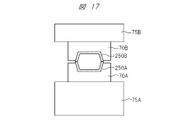
- FIG. 17 is a diagram for explaining the operation of the molded product manufacturing apparatus continued from FIG. 16;
- FIG. 4 is a plan view schematically showing a state in which a partially molded product fitted in a mold is fixed by a plurality of chuck portions; It is a figure which shows an example of the fixing method of the partial molded product by a chuck part. It is a figure which shows an example of the fixing method of the partial molded product by a chuck part.
- FIG. 10 is a diagram showing another example of a method of fixing a partially molded product by means of a chuck; FIG.
- FIG. 10 is a diagram showing another example of a method of fixing a partially molded product by means of a chuck; It is a figure explaining operation
- FIG. 24 is a diagram for explaining the operation of the molded product manufacturing apparatus continued from FIG. 23;
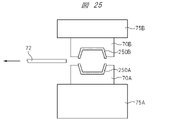
- FIG. 25 is a diagram for explaining the operation of the molded product manufacturing apparatus continued from FIG. 24;
- It is a figure explaining a welding process.
- FIG. 28 is a diagram for explaining the operation of the molded product manufacturing apparatus continued from FIG. 27;
- FIG. 29 is a diagram for explaining the operation of the molded product manufacturing apparatus continued from FIG. 28;
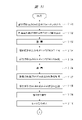
- FIG. 30 is a diagram for explaining the operation of the molded product manufacturing apparatus continued from FIG. 29; It is a flow chart explaining operation of a cast manufacturing device. It is a flow chart explaining operation of a cast manufacturing device. It is a figure explaining room for improvement. It is a figure explaining the 1st devised point.
- FIG. 4 is a diagram schematically showing a “horizontal configuration”; It is a figure explaining a 1st solution.
- FIG. 10 is a diagram showing a specific configuration example 1;
- FIG. 11 is a diagram showing a specific configuration example 2; It is a figure explaining the structure which provides a centering mechanism. It is a figure which shows the fixing mechanism which fixes the heater comprised from a non-contact heater.
- FIG. 4 is a diagram schematically showing a “horizontal configuration”; It is a figure explaining a 1st solution.
- FIG. 10 is a diagram showing a specific configuration example 1;
- FIG. 11 is a diagram showing a specific configuration example 2; It
- FIG. 10 is a diagram showing a configuration example employing a centering mechanism, which is a third contrived point, as a fixing mechanism for fixing a heater composed of a non-contact heater.
- (a) and (b) are diagrams showing the operation of the centering mechanism. It is a figure which shows a rack and pinion type centering mechanism. It is a figure explaining the centering mechanism of a link mechanism system.
- Hollow molded articles having internal cavities are formed, for example, using injection molding techniques. At this time, it is rare to integrally manufacture a hollow molded product by injection molding technology, and most hollow molded products are often manufactured by combining a plurality of partial molded products manufactured by injection molding technology.
- an integrally molded product 10 is manufactured by bonding a partially molded product 1A and a partially molded product 1B that are separately manufactured by injection molding technology.
- injection molding technology is also used when bonding multiple partial molded products. That is, instead of using an adhesive to bond a plurality of partial molded products, the injected molten resin is poured into the joining portion to bond the plurality of partial molded products.
- die slide injection method there is a technique called "die slide injection method”.
- the "die slide injection method” will be referred to as the “DSI method” and the “DSI method” will be described.
- 3A to 3C are schematic diagrams for explaining the "DSI method”.
- a mold 20A having a first molding region for forming a partial molded product 2A and a mold 20B having a second molding region for forming a partial molded product 2B are prepared. . Then, by pouring the molten resin into the mold 20A and the mold 20B in a "closed" state, the partial molded product 2A is formed in the first molding region of the mold 20A, and the second molding of the mold 20B is performed. A partial molded product 2B is formed in the region.
- the mold 20B by sliding the mold 20B with respect to the mold 20A while the molds are open, the partial molded product 2A and the partial molded product 2B are positioned to face each other. Deploy. After that, as shown in FIG. 3(c), the mold 20A and the mold 20B are "closed", and the molten resin is poured into the joining portion between the partial molded product 2A and the partial molded product 2B. As a result, the partial molded product 2A and the partial molded product 2B are adhered with the molten resin to manufacture an integrally molded product.
- a heater is inserted between the two partial molded products, and the heat generated from the heater is generated.
- a technique has been developed for bonding two partial molded products together by melting the joint regions of the two partial molded products themselves with the heat generated and then applying pressure to the melted joint regions.
- a technique improved from this "DSI method” is called a "hot plate-die slide injection method” because it uses a heater.
- FIG. 4 is a diagram showing a configuration example of a molded product manufacturing system that implements the "HP-DSI method”.
- the molded product manufacturing system 100 has a mold clamping device 30 attached to a movable platen 31 .
- This mold clamping device 30 is configured to be able to variably control the distance between the movable platen 31 and the fixed platen 35 .
- a movable mold 32 and a fixed mold 33 can be arranged between the movable platen 31 and the fixed platen 35 .
- the distance between the movable mold 32 and the fixed mold 33 is shortened to close the mold.
- the distance between the movable mold 32 and the fixed mold 33 can be increased to "open the mold".
- a closed space is formed between the movable mold 32 and the fixed mold 33. is formed.
- two closed spaces are formed at different positions.
- the partial molded product 45A is formed by pouring the resin into the closed space
- the partial molded product 45B is formed by pouring the resin into the other closed space.
- a slide mechanism 32A is attached to the movable mold 32, and the slide mechanism 32A is configured so that the position of the movable mold 32 can be slid with respect to the fixed mold 33.
- a hot runner manifold (in-mold flow path) 34 is formed inside the fixed mold 33. By flowing resin through the hot runner manifold 34, the space between the movable mold 32 and the fixed mold 33 is " Resin is injected into the two closed spaces formed when the mold is closed.
- an injection device 41 for extruding resin is connected to the stationary platen 35 , and the resin extruded from the injection device 41 is injected into the fixed die 33 through the stationary platen 35 . It is designed to flow into a hot runner manifold 34 formed in the .
- This injection device 41 has a hopper 40 for putting resin raw material and a cylinder (barrel) 38 .
- the resin raw material is put into the hopper 40 , the resin raw material is kneaded by the rotatable screw 37 arranged inside the cylinder 38 .
- a heater 39 is arranged around the cylinder 38, and the resin raw material put into the inside of the cylinder 38 is heated by the heater 39 and kneaded by the screw 37 to become a molten resin.
- a screw head backflow prevention ring 36 is provided inside the cylinder 38 to prevent backflow of the molten resin when the screw 37 advances (during injection).
- the movable mold 32 and the fixed mold 33 are arranged between the movable platen 31 and the fixed platen 35. As shown in FIG. Then, by moving the movable platen 31 closer to the fixed platen 35 by the mold clamping device 30 , “mold closing” is performed between the movable mold 32 and the fixed mold 33 . As a result, two closed spaces are formed between the movable mold 32 and the fixed mold 33, as shown in FIG.
- the resin raw material is put into the cylinder 38 from the hopper 40 of the injection device 41, and the inside of the cylinder 38 is The resin raw material is kneaded by the screw 37 arranged in the . As a result, the resin raw material becomes molten resin. This molten resin is extruded from the inside of the cylinder 38 . The extruded molten resin is injected into each of the two closed spaces formed between the movable mold 32 and the fixed mold 33 via the hot runner manifold 34 formed inside the fixed mold 33. . As a result, the molten resin is solidified in one sealed space to form a partial molded product 45A, and the molten resin is solidified in the other sealed space to form a partial molded product 45B.
- the movable platen 31 is moved away from the fixed platen 35 by the mold clamping device 30 to "open" the movable mold 32 and the fixed mold 33 .
- the movable mold 32 is slid with respect to the fixed mold 33 by the slide mechanism 32A.
- the molded part 45B is arranged at a position facing the molded part 45A.
- the heater slide mechanism provided in the molded product manufacturing system 100 inserts the heater 42 between the partially molded product 45A and the slid partial molded product 45B. That is, the heater 42 is inserted into the cavity formed between the fixed mold 33 and the slid movable mold 32 . Then, the heat supplied from the heated heater 42 heats and melts the portion that will be the joint portion between the partial molded product 45A and the partial molded product 45B.
- the mold clamping device 30 moves the movable platen 31 closer to the fixed platen 35, thereby separating the movable mold 32 and the fixed mold. 33 is "mold closed".
- the partial molded product 45A and the partial molded product 45B are fused together by applying pressure to the melted joining portion of the molded partial product 45A and the molded partial product 45B.
- the movable platen 31 is moved away from the fixed platen 35 by the mold clamping device 30 to "open" the space between the movable mold 32 and the fixed mold 33.
- An integrally molded product 45 formed by welding the molded product 45A and the partial molded product 45B is taken out.
- the partial molded product 45A and the partial molded product 45B are partially melted by the heat supplied from the heater 42 and adhered.
- the “HP-DSI method” of manufacturing the integrally molded product 45 is realized. Such "HP-DSI method” can supply a sufficient amount of heat and apply pressure to the joining portion between the partial molded product 45A and the partial molded product 45B. It is excellent in that strength can be obtained.
- a partial molded product 45A is formed in one of two closed spaces formed between the movable mold 32 and the fixed mold 33 by injection molding technology, and A partial molded product 45B is formed in the other closed space. Then, without removing the partial molded product 45A formed in one closed space and the partial molded product 45B formed in the other closed space, the partial molded product 45B is slid, and then the partial molded product 45A and the partial molded product are formed by the heater 42.
- the integrally molded product 45 is manufactured by melting and adhering the joining portion with the product 45B. That is, in the "HP-DSI method", the molded parts 45A and 45B are processed without being removed from between the movable mold 32 and the fixed mold 33 from the first step to the last step.
- the synthetic resin forming the partial molded product 45A and the partial molded product 45B tends to shrink.
- Shrinkage of the resin may cause the partial molded product 45A and the partial molded product 45B to come off.
- the integrally molded product 50 cannot be manufactured.
- the first room for improvement in the "HP-DSI method” is that the molded parts 45A and 45B tend to separate due to shrinkage of the resin.
- the integrally molded product 45 is manufactured by combining the partially molded product 45A and the partially molded product 45B.
- the size of this integrally molded product 45 is large, it is necessary to increase the size of the molded product manufacturing system 100 that implements the “HP-DSI method”.
- the second room for improvement in the "HP-DSI method" is that as the size of the integrally molded product 45 increases, not only the movable mold 32 and the fixed mold 33 themselves, but also the slide mechanism 32A will increase in size. As a result of the necessity, the molded product manufacturing system 100 including these components tends to be enlarged.
- FIG. 7 is a diagram schematically showing the "HP-IWM” system.
- the “HP-IWM” system 150 includes an injection molding machine 160, an injection molding machine 170, a take-out device 160A, a take-out device 170A, a conveyor 160B, a conveyor 170B, a robot arm 180, and a molded product. It has a manufacturing apparatus 200 and a conveyor 190 .
- Injection molding apparatus 160 is configured to produce molded parts 50A, which are removed from injection molding apparatus 160 by take-out device 160A and placed on conveyor 160B. be transported.
- the injection molding machine 170 is configured to produce a molded part 50B, and the molded part 50B produced by the injection molding machine 170 is removed from the injection molding machine 170 by a removal device 170A and It is conveyed by the conveyor 170B.
- the robot arm 180 is configured to convey the partial molded product 50A conveyed by the conveyor 160B to the molded product manufacturing apparatus 200, and to convey the partial molded product 50B conveyed by the conveyor 170B to the molded product manufacturing apparatus 200. It is
- the molded product manufacturing apparatus 200 inserts the partial molded product 50A and the partial molded product 50B conveyed by the robot arm 180 into the respective molds, and performs the By applying heat supplied from the heater, the partial molded product 50A and the partial molded product 50B are partially melted and adhered to each other, thereby manufacturing the integrally molded product 50 .
- the robot arm 180 also has the function of transporting the integrally molded product 50 manufactured by the molded product manufacturing apparatus 200 from the molded product manufacturing apparatus 200 to the conveyor 190 .
- FIG. 8 is a flow chart explaining the outline of the operation of the "HP-IWM" system.
- the molded partial molded product 50A is removed from the injection molding device 160 by the removal device 160A (S12). Then, the partial molded product 50A taken out by the take-out device 160A is conveyed by the conveyor 160B (S13).
- the molded partial molded product 50B is taken out from the injection molding device 170 by the take-out device 170A (S22). . Then, the partial molded product 50B taken out by the take-out device 170A is conveyed by the conveyor 170B (S23).
- the partial molded product 50A conveyed by the conveyor 160B is carried into the molded product manufacturing apparatus 200 by the robot arm 180, and the partial molded product 50B conveyed by the conveyor 170B is also transported by the robot arm 180. It is carried into the molded product manufacturing apparatus 200 .
- each of molded parts 50A and 50B is fitted into a mold (S31).
- the heater heats the joint portions of the molded product parts 50A and 50B fitted in the mold (S32).
- the portions to be the joint portions of the partial molded product 50A and the partial molded product 50B are melted.
- the melted parts are welded (S33) to bond the partially molded product 50A and the partially molded product 50B to manufacture the integrally molded product 50.
- the integrally molded product 50 manufactured by the molded product manufacturing apparatus 200 is transported to the conveyor 190 by the robot arm 180 after being taken out from the molded product manufacturing apparatus 200 (S34).
- the integrally molded product 50 can be manufactured.
- FIG. 9 is a diagram showing the configuration of the main parts of the injection molding apparatuses 160 and 170. As shown in FIG.
- an injection molding apparatus 160 has a movable platen 52 and a stationary platen 53 connected to tie bars 51, and the movable platen 52 connected to the tie bars 51 is configured to be movable.
- a movable mold 54 and a fixed mold 55 can be arranged between the movable platen 52 and the fixed platen 53 .
- the distance between the movable mold 54 and the fixed mold 55 can be shortened to close the mold.
- the distance between the movable mold 54 and the fixed mold 55 can be increased to "open the mold".
- a sealed space is formed between the movable mold 54 and the fixed mold 55.
- 50A is formed.
- a hot runner manifold (in-mold flow path) 56 is formed inside the fixed mold 55 . Resin can be injected into the closed space formed when the mold is closed.
- the injection device 41 is connected to the fixed mold 55.
- the injection device 41 has the functions of rotating and moving the screw forward and backward, and can plasticize, melt, weigh, and inject the resin. Resin injected from the injection device 41 flows into a hot runner manifold 56 formed inside a fixed mold 55 .
- This injection device 41 has a hopper 61 for putting resin raw material and a cylinder (barrel) 59 .
- the resin raw material is put into the hopper 61 , the resin raw material is kneaded by the rotatable screw 58 arranged inside the cylinder 59 .
- a heater 60 is arranged around the cylinder 59, and the resin raw material put into the cylinder 59 is kneaded by the screw 58 while being heated by the heater 60 to become a molten resin.
- a screw head backflow prevention ring 57 is provided inside the cylinder 59 to prevent backflow of the molten resin when the screw 58 advances (during injection).
- the injection molding apparatus 160 is equipped with a take-out device 160A for taking out the manufactured partial molded product 50A.
- a chuck 62 is provided for this purpose.
- a movable mold 54 and a fixed mold 55 are arranged between a movable platen 52 and a fixed platen 53.
- the movable platen 52 is moved closer to the fixed platen 53 to "close” the movable mold 54 and the fixed mold 55.
- a closed space is formed between the movable mold 54 and the fixed mold 55, as shown in FIG.
- the resin raw material is charged into the cylinder 59 from the hopper 61 of the injection device 41, and the inside of the cylinder 59 is heated by the heater 60 arranged around the cylinder 59 while the charged resin raw material is The resin raw material is kneaded by the screw 58 arranged in the . As a result, the resin raw material becomes molten resin.
- This molten resin is metered into the cylinder 59 by retreating the screw and injected by advancing the screw.
- the injected molten resin is injected into the closed space formed between the movable mold 54 and the fixed mold 55 through the hot runner manifold 56 formed inside the fixed mold 55 .
- the molten resin is solidified in the sealed space to form the partial molded product 50A.
- the movable platen 52 is moved away from the fixed platen 53, thereby "opening" the movable mold 54 and the fixed mold 55.
- the partial molded product 50A is sucked by a chuck 62 provided in the unloading device 160A.
- the partial molded product 50A sucked by the chuck 62 is placed on, for example, a conveyor 160B shown in FIG. 7 and conveyed.
- FIG. 12 is a schematic diagram showing the external configuration of the molded product manufacturing apparatus 200. As shown in FIG.
- the molded product manufacturing apparatus 200 can be provided not only as a dedicated apparatus, but also, for example, by modifying a general-purpose press apparatus. Specifically, it can be realized by installing a die, a heater, a heater slide mechanism, and a heater slide control section in a general-purpose press apparatus.
- This molded product manufacturing apparatus 200 is configured to manufacture an integrally molded product by partially melting and adhering two partial molded products by heat supplied from a heater, and has the following configuration. ing.
- the molded product manufacturing apparatus 200 has a mold 70A, a mold 70B, a contact/non-contact control section 71, a heater 72, a heater slide mechanism 73, and a heater slide control section 74.
- the mold 70A is configured so that the partial molded product 250A manufactured by one of the injection molding apparatuses can be fitted therein, and is fixed to the stage. Therefore, the mold 70A can be said to be a fixed mold fixed to the stage.
- This stage functions as a mold mounting portion 75A for mounting the mold 70A.
- the mold 70A is formed with a recess into which the partially molded product 250A is fitted.
- the mold 70B is configured, for example, so that the partial molded product 250B manufactured by the other injection molding device can be fitted.
- the mold 70B is arranged at a position facing the mold 70A and is movable so that the distance between the fixed mold 70A and the mold 70B can be changed. Therefore, the mold 70B can be said to be a movable mold that can move.
- the mold 70B is mounted on the mold mounting portion 75B.
- the mold 70B is formed with a recess, and the partial molded product 250B is fitted into this recess.
- the contact/non-contact control unit 71 is configured to control contact/non-contact between the molded part 250A fitted in the mold 70A and the molded part 250B fitted in the mold 70B. Specifically, the contact/non-contact control unit 71 controls the “mold closing”/“mold opening” between the mold 70A and the mold 70B, so that the partial molded product 250A and the partial molded product 250B are separated from each other. Controls contact/non-contact between For example, the contact/non-contact control unit 71 can control "mold closing"/"mold opening" between the mold 70A and the mold 70B by controlling the movement of the mold 70B. It is configured.
- the contact/non-contact control section 71 can also be called a variable control section that variably controls the distance between the mold mounting section 75A and the mold mounting section 75B.
- Heater 72 is configured to be insertable between partial molded product 250A fitted in mold 70A and partial molded product 250B fitted in mold 70B. It is configured to be able to heat the portion that is to be the joining portion between the partial molded product 250A and the partial molded product 250B while being inserted between the two.
- the heater 72 is configured to be movable so as to be inserted into a cavity formed between the mold 70A in which the molded part 250A is placed and the mold 70B in which the molded part 250B is placed. 2, the heater 72 is inserted into the cavity so as to heat the joint portion between the partial molded product 250A and the partial molded product 250B.
- the heater slide mechanism 73 is fixed to one of the mold 70A, the mold 70B, the mold mounting portion 75A, and the mold mounting portion 75B, and slides the heater 72 between the molded parts 250A and 250B.
- the heater 72 is configured to be slid in order to be inserted or retracted from between the molded parts 250A and 250B. That is, the heater slide mechanism 73 is configured to allow the heater 72 to slide between the inserted position and the retracted position.
- the heater slide mechanism 73 is controlled by a heater slide control section 74 .
- a mold 70A is placed on a stage 75A, and a partially molded product (first workpiece) 250A is fitted into this mold 70A.
- a mold 70B is arranged at a position facing the mold 70A, and a partially molded product (second work) 250B is fitted in this mold 70B.
- the contact/non-contact control section 71 is configured to control movement of the mold 70B by movement of the stage 75B.
- the contact/non-contact control unit 71 controls the movement of the mold 70B to adjust the distance between the molded part 250A fitted in the mold 70A and the molded part 250B fitted in the mold 70B.
- it is configured to control contact/non-contact.
- the contact/non-contact control section 71 has a function of controlling the distance between the mold 70A and the mold 70B or "mold closing"/"mold opening".
- the molded product manufacturing apparatus 200 has a heater 72 .
- the heater 72 is connected to a heater slide mechanism 73 so that it can slide in the arrow direction (horizontal direction) in FIG. 12 by the heater slide mechanism 73 .
- the heater slide control section 74 is configured to control the temperature and output of the heater slide mechanism 73 and the heater.
- the heater slide mechanism 73 is controlled by the heater slide control unit 74 so that the heater 72 is inserted between the molded parts 250A and 250B or retracted from between the molded parts 250A and 250B. It's like
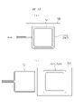
- FIGS. 13(a) and 13(b) are views seen from the top of FIG. 12, and are plan views schematically showing the movement of the heater 72.
- FIG. The heater 72 is configured to be slidable between an insertion position (FIG. 13(a)) that planarly overlaps the mold 70B and a retracted position (FIG. 13(b)) that does not planarly overlap the mold 70B.
- FIG. 13(a) when the heater 72 is arranged at the insertion position overlapping the mold 70B in plan view, the position where the heater 72 heats the welded part of the molded part 250B and the molded part 250A is They overlap. As a result, the heater 72 can heat the joint portion between the molded parts 250A and 250B.
- the molded product manufacturing apparatus 200 is configured as described above.
- the heater 72 used in the "HP-IWM method" may be composed of a non-contact heater or a contact heater.
- non-contact heaters include carbon heaters and halogen heaters, but any heater can be used as long as it can heat the partial molded product without contact by irradiating infrared rays, near-infrared rays, or the like.
- a heating plate can be mentioned as a contact heater.
- the heating plate is, for example, a cartridge heater that heats a plate made of metal such as iron, aluminum, brass, or copper, a ceramic heater that insulates the heating element by sandwiching it between ceramics such as alumina or silicon nitride, or a heat-resistant heating element. Any type can be used as long as it can heat the welding part, such as a film-shaped heater insulated by sandwiching it with a film.
- non-contact heater The advantage of using a non-contact heater is that it does not come into contact with the partial molded product, so it can be heated in a clean state, but it is difficult to adjust the temperature.
- contact heaters offer the advantage of easier temperature control than non-contact heaters.
- Both the non-contact heater and the contact heater may have a shape that can heat the entire projected surface of the partial molded product, or may have a shape that can selectively heat only the welded part of the partial molded product.
- the resin in the non-heated portion will not melt and the portion will not be joined.
- the heater is required to have a function of uniformly heating the welded portion by adjusting its shape and output characteristics.
- the detailed operation of the molded product manufacturing apparatus 200 will be described below, but the operation differs depending on whether the heater 72 is a non-contact heater or a contact heater. For this reason, first, the operation when the heater 72 is configured as a non-contact heater will be described, and then the operation when the heater 72 is configured as a contact heater will be described.
- the partially molded product 250A is fitted in the mold 70A (S101 in FIG. 14), and the partially molded product 250B is fitted in the mold 70B (S102 in FIG. 14).
- the mold 70B is moved downward under the control of the contact/non-contact control section 71, so that the mold 70A and the mold 70B are separated into the partial molded product 250A and the partial molded product 250B.
- the mold is "closed" to the position where the joint portions are in close contact (S103 in FIG. 14).
- FIG. 18 is a plan view schematically showing a state in which a partially molded product fitted in a mold is fixed by a plurality of chuck portions.
- the partially molded product 250A fitted in the mold 70A is fixed by a plurality of chuck portions 80A (S104 in FIG. 14).
- the partial molded product 250B fitted in the mold 70B is fixed by a plurality of chuck portions 80B (S105 in FIG. 14).
- the mold 70A has a plurality of chuck portions 80A that fix the partial molded product 250A.
- the mold 70B has a plurality of chuck portions 80B that fix the partial molded product 250B.
- the number of chucks can be appropriately determined according to the size of the molded product. Fixing of the molded part 250A (S104) and fixing of the molded part 250B (S105) may be performed at the same time.
- FIGS. 19 and 20 are diagrams showing an example of a method of fixing a partially molded product by means of a chuck portion.
- a flange 90 is provided at the tip of the partially molded product 250A fitted in the mold 70A.
- the chuck portion 80A is composed of a partial core 81 and an air cylinder 82.
- FIGS. 19 and 20 by inserting the partial core 81 into the flange 90 by the pushing force of the air cylinder 82, the partial molded product 250A can be fixed by the chuck portion 80A.
- 21 and 22 are diagrams showing another example of the method of fixing the molded part 250A by the chuck part 80A and the method of fixing the molded part 250B by the chuck part 80B.
- the chuck portion 80A has a partial core 83A and an air cylinder 84A, and the partial core 83A and the air cylinder 84A are connected.
- the chuck portion 80B has a partial core 83B and an air cylinder 84B, and the partial core 83B and the air cylinder 84B are connected.
- the distal end portion of the partial core 83A and the distal end portion of the partial core 83B have a "saw blade shape" that is easy to press and pull out. At this time, as shown in FIGS.
- the partial core 83A is pressed against the end portion of the partial molded product 250A by the pushing force of the air cylinder 84A, thereby fixing the partial molded product 250A with the chuck portion 80A. can.
- the partial core 83B against the end of the partial molded product 250B with the pushing force of the air cylinder 84B, the partial molded product 250B can be fixed by the chuck portion 80B.
- the chucking state of the partial molded products 250A and 250B can be monitored.
- Either one type of chuck mechanism shown in FIGS. 19 and 21 may be used, or a combination of multiple types may be used. Other mechanisms may be used as long as they can chuck the partially molded product.
- the air cylinders 84A, 84B may be hydraulic cylinders.
- the partial cores 83A and 83B may be pressed against the ends of the partial molded products 250A and 250B by the elastic force of springs.
- the partial cores 83A, 83B may be moved by a motor.
- the mold 70A and the mold 70B are "opened” by moving the mold 70B upward under the control of the contact/non-contact control unit 71 (S106 in FIG. 14).
- the monitoring unit 91 monitors the fitting state of the partial molded product 250A fitted in the mold 70A (S107 in FIG. 14), and also the partial molded product 250B fitted in the mold 70B. The fitting state is monitored by the monitoring unit 91 (S108 in FIG. 14).
- the monitoring unit 91 has an imaging device 92A, an imaging device 92B, and a monitoring control unit 93.
- the imaging device 92A is configured to capture an image of the fitted state of the molded part 250A
- the imaging device 92B is configured to capture an image of the fitted state of the molded part 250B.
- the monitoring control unit 93 monitors whether or not the fitting state of the partial molded product 250A is good based on the image captured by the imaging device 92A, and also monitors whether the partial molded product 250A is properly fitted based on the image captured by the imaging device 92B. It is configured to monitor whether or not the fitting state of the molded product 250B is good.
- the imaging device 92A and the imaging device 92B commercially available cameras for monitoring the state of molds can be used.
- the imaging devices 92A and 92B may monitor the states of the molded parts 250A and 250B with a single device, or the states of the molded parts 250A and 250B may be divided into parts by a plurality of devices. can be monitored.
- the operation of the molded product manufacturing apparatus 200 is continued.
- the monitoring unit 91 determines that at least one of the fitting state of the molded product part 250A and the fitting condition of the molded product part 250B is not good, the operation of the molded product manufacturing apparatus 200 is stopped. can take This can be expected to prevent the production of defective products or damage to the mold.
- the mold 70A and the mold 70B are partially “closed” by moving the mold 70B slightly downward under the control of the contact/non-contact control unit 71 ( S109 in FIG. 14). Then, the heater slide mechanism 73 is controlled by the heater slide control unit 74 to slide the heater 72 and insert it between the molded parts 250A and 250B (S110 in FIG. 14).
- the heater 72 is heated (S111 in FIG. 14). As a result, the heat supplied from the heater 72 melts the portion that will be the joining portion between the molded partial product 250A and the molded partial product 250B. Thereafter, as shown in FIG. 25, the heater slide mechanism 73 is controlled by the heater slide control unit 74 to slide the heater 72 and retract the heater 72 from between the molded parts 250A and 250B. (S112 in FIG. 15).
- the molds 70A and 70B are completely "closed” by moving the mold 70B downward under the control of the contact/non-contact control unit 71 (S113 in FIG. 15).
- a predetermined pressure is applied for a predetermined period of time measured by a timer, or a predetermined amount of pressure is applied.
- the melted resin oozes out and the joint portions of the molded parts 250A and 250B are welded.
- the partially molded product 250A and the partially molded product 250B are integrated to form the integrally molded product 50.
- the fixing of the integrally molded product 50 by the chuck portion 80A is released (S114 in FIG. 15).
- FIG. 28 by moving the mold 70B upward under the control of the contact/non-contact control section 71, the mold 70A and the mold 70B are “opened” and the hydraulic ejection pins 95 are moved. pushes up the integrally molded product 250 (S115 in FIG. 15).
- the fixing of the integrally molded product 50 by the chuck portion 80B is released (S116 in FIG. 15).
- the integrally molded product 250 is finally taken out by projecting the ejector pin 96 (S117 in FIG. 15).
- the order of removing the chuck parts 80A and 80B is not limited to this.
- the fixation by the chuck portion 80A is released first, but the fixation by the chuck portion 80B may be released first by switching the A side and the B side.
- the integrally molded product 250 can be manufactured by operating the molded product manufacturing apparatus 200 according to the present embodiment.
- Figures 31 and 32 are flowcharts for explaining the operation of the molded product manufacturing apparatus.
- FIGS. 31 and 32 are almost the same as the flowcharts shown in FIGS. 14 and 15, so the different points will be mainly described.
- steps S101 to S110 are the same.
- the heater 72 is inserted between the molded parts 250A and 250B (S110 in FIG. 31).
- a gap exists between the heater 72 and the partial molded products 250A and 250B.
- the heater 72 is out of contact with the molded parts 250A and 250B.
- the mold 70A and the mold 70B are "closed” by moving the mold 70B downward under the control of the contact/non-contact control section 71.
- the heater 72 is brought into contact with and sandwiched between the molded parts 250A and 250B.
- the “mold closing” at this time is adjusted so that the pressing force is weak so as not to damage the heater 72 .
- the heater 72 is heated while being in contact with the molded parts 250A and 250B. As a result, the portion that will be the joining portion between the molded partial product 250A and the molded partial product 250B is melted (S201 in FIG. 32).
- the mold 70A and the mold 70B are "opened” by moving the mold 70B upward under the control of the contact/non-contact control unit 71 (S202 in FIG. 32).
- the heater slide mechanism 73 is controlled by the heater slide control unit 74 to slide the heater 72 and retract the heater 72 from between the molded parts 250A and 250B (S112 in FIG. 32). .
- the subsequent steps are the same.
- the integrally molded product 250 can be manufactured.
- the first characteristic point of this embodiment is that, in the technology of manufacturing an integrally molded product by partially melting and adhering two partially molded products by heat supplied from a heater, the partially molded product is attached to a mold.
- the point is that it has a step of fitting. As a result, even if the resin forming the partially molded product shrinks, it is possible to prevent the partially molded product from coming off the mold.
- the partially molded product is processed without being removed from the mold.
- the synthetic resin that constitutes the partially molded product has the property of shrinking. For this reason, if the partial molded product is processed from the first process to the last process without removing it from the mold, there is a possibility that the synthetic resin will shrink in the middle process and the partial molded product will come off the mold. be.
- a partially molded product manufactured by another device is fitted into the mold.
- the mold can be designed in consideration of the shrinkage of the resin forming the partial molded product, the possibility of the partially molded product coming off the mold can be reduced.
- it is possible to improve the manufacturing yield of integrally molded products.
- a second characteristic point of the present embodiment is that, for example, as shown in FIGS. 18 to 22, a chuck portion is provided for fixing the partially molded product fitted in the mold.
- a chuck portion is provided for fixing the partially molded product fitted in the mold.
- the third characteristic point of this embodiment is that it has a monitoring unit configured to monitor the fitting state of the partially molded product, as shown in FIG. 23, for example. Accordingly, even if the partially molded product is detached from the mold, it can be detected by the monitoring unit. Then, for example, when the monitoring unit detects an abnormality such as a lift of the partially molded product, it is possible to stop the production line. Therefore, according to the third characteristic point of the present embodiment, it is possible to prevent the production of defective products, and from this point as well, it is possible to further improve the production yield of integrally molded products. .
- the technical idea of the present embodiment is to manufacture an integrally molded product by melting and adhering the joint portions of a plurality of partially molded products by heat supplied from a heater.
- the heater plays an important role in improving the performance of the molded product manufacturing apparatus.
- the performance of the molded product manufacturing apparatus is improved by focusing on the heater and applying various ideas related to the heater.
- FIG. 33 is a diagram for explaining room for improvement.
- the portion that will be the joining portion between the partial molded product 250A fitted in the mold 70A and the partial molded product 250B fitted in the mold 70B is inserted between the mold 70A and the mold 70B. It is melted by being heated by the heater 72 . Thereafter, since the heater 72 becomes an obstacle to welding the melted portion, the heater 72 is retracted to the outside of the mold 70A and the mold 70B, as shown in FIG.
- the stroke L1 in order to reliably retract the heater 72 to a position where it does not contact the mold 70A and the mold 70B, it is necessary to take a long stroke L1 shown in FIG.
- the stroke L1 if the stroke L1 is lengthened, the overall length of the device will be lengthened, which will lead to an increase in the size of the molded product manufacturing device.
- the longer stroke L1 means longer cycle time for sliding the heater 72 between the insertion position and the retracted position, which leads to a decrease in throughput.
- the sliding distance of the heater 72 becomes longer, and the vibration (flexure) of the supporting portion that supports the heater 72 also becomes larger. This means that it becomes difficult for the heater 72 to uniformly heat the bonding site. From the above, it is desirable that the stroke for sliding the heater 72 is as short as possible.
- FIG. 34 is a diagram explaining the first devised point.
- a notch portion 300 is provided in the mold 70B.
- This cutout portion 300 functions as a standby place (retreat place) for the heater 72 . That is, when the heater 72 moves to the standby position outside the cavity formed by the molds 70A and 70B, the heater 72 and the notch 300 overlap in plan view.
- the first devised point is to provide the notch portion 300, which serves as a retreating place for the heater 72, in the mold 70B.
- the notch 300 may be provided in the mold 70A instead of in the mold 70B, or may be provided in both the mold 70B and the mold 70A.
- the stroke L2 for sliding the heater 72 becomes shorter than the stroke L1 shown in FIG. 33 where the notch 300 is not provided.
- the stroke L2 is shortened, and as a result, the overall length of the apparatus can be shortened, thereby suppressing an increase in the size of the molded product manufacturing apparatus.
- the cycle time for reciprocating sliding of the heater 72 can be shortened. This means that the throughput is improved.
- the shortening of the time required for the heater 72 to slide from the insertion position to the retracted position means that the time until welding of the melted portion performed after retracting the heater 72 is shortened. Shortening the time until the melted portion is welded means that the temperature drop of the melted portion can be suppressed. As a result, the fusion portion can be welded while maintaining a high temperature. Therefore, according to the first devised point, it is also possible to improve the bonding reliability of the melted portion.
- the length of the supporting portion (for example, the supporting arm) that supports the heater 72 can be shortened, it is possible to suppress shaking (deflection) of the supporting portion. As a result, according to the first devised point, it is possible to realize uniform heating in the portion that will be the joining portion.
- the sliding time of the heater 72 can be shortened.
- uniform heating can be realized to improve the bonding reliability of the bonding portion, which is a remarkable effect that cannot be obtained by conventional techniques.
- the first devised point has a very excellent technical significance in that a large effect can be obtained without increasing the cost.
- the second devised point is the devised point for the room for improvement that becomes apparent in the "horizontal configuration".
- the room for improvement that becomes apparent especially in the “horizontal configuration” will be described.
- FIG. 35 is a diagram schematically showing the "horizontal configuration”.
- a mold 70A and a mold 70B are arranged facing each other in the horizontal direction.
- a heater 72 is inserted in the gap between the mold 70A and the mold 70B.
- cold air flows into the gap from below, and the cold air that has flowed in is warmed by the heater 72 .
- the warmed air flows toward the upper side of the gap.
- the heater 72 inserted in the gap between the mold 70A and the mold 70B heats in this way, convection occurs in the air existing in the gap, resulting in a temperature difference between the lower side and the upper side of the gap. That is, a temperature distribution occurs in the gap.
- FIG. 36 is a diagram explaining the first solution.
- a swing mechanism 400 is connected to the heater 72 that can be inserted into the gap between the mold 70A and the mold 70B.
- the rocking mechanism 400 has, for example, a forward/backward movement mechanism 410 configured to move the heater back and forth, a rotatable motor 420, and an eccentric cam 430 attached to the motor.
- the heater 72 connected to the swing mechanism 400 can perform a swing motion (swing motion).
- the first solution is to connect the swinging mechanism 400 to the heater 72, thereby swinging the heater 72 inserted into the gap between the mold 70A and the mold 70B.
- the air present in the gap is agitated by the heater 72 that is oscillating, thereby suppressing non-uniformity in temperature caused by convection.
- the swing mechanism 400 in the molded product manufacturing apparatus, which increases the manufacturing cost of the molded product manufacturing apparatus.
- the heater 72 since the heater 72 is caused to swing, it is necessary to secure a distance between the heater 72 and the molds 70A and 70B in order to avoid collision between the heater 72 and the molds 70A and 70B. There is This means that the distance between the heater 72 and the partial molded product fitted in the mold 70A or the partial molded product fitted in the mold 70B is increased, and the thermal energy generated by the heater 72 is efficiently dissipated. There is room for improvement that is not well exploited.
- the basic idea of the second solution is to improve the temperature uniformity of the gap by providing a convection suppression member that suppresses the air convection that causes the temperature non-uniformity in the gap between the molds 70A and 70B. It is a thought that
- FIG. 37 is a diagram showing a specific configuration example 1.
- the mold 70A is provided with a cover 440 to cover the upper side of the gap and a cover 450 to cover the lower side of the gap.
- the cover 450 suppresses the inflow of cold air from the lower side of the gap
- the cover 440 suppresses the outflow of warm air from the upper side of the gap.
- the covers 440 and 450 suppress air convection caused by heat generated from the heater 72 inserted into the gap. That is, cover 440 and cover 450 function as convection suppression members that suppress convection caused by heat supplied from the heater. In this way, according to Specific Configuration Example 1, it is possible to improve the temperature uniformity of the gap.
- FIG. 37 illustrates a configuration in which the cover 440 and the cover 450 are provided on the mold 70A
- the configuration is not limited to this, and for example, a configuration in which the cover 440 and the cover 450 are provided on the mold 70B may be employed.
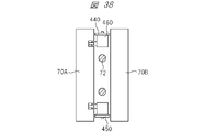
- FIG. 38 is a diagram showing a second specific configuration example.
- an outer frame body 460 arranged outside the heater 72 together with the heater 72 is inserted into the gap. That is, in the specific configuration example 2, the heater slide mechanism is configured to slide the slide unit, which is an integral structure composed of the heater 72 and the outer frame 460 arranged outside the heater 72 .
- the outer frame 460 functions as a convection suppression member that suppresses convection caused by heat supplied from the heater. Further, by attaching the covers 440 and 450 for preventing convection to the outside of the outer frame 460, the effect of suppressing the convection can be further enhanced. In this manner, according to Specific Configuration Example 2, the temperature uniformity of the gap can be improved.
- the outer frame 460 has a function as a convection suppressing member, but since the outer frame 460 also has another function, the other function of the outer frame 460 will be described.
- the outer frame body 460 collides with the heater 72 first. In this case, a torque abnormality or the like occurs in the heater slide mechanism that slides the outer frame body 460 . Therefore, the heater 72 can be protected by detecting this torque abnormality and stopping the device.
- the outer frame 460 has not only a function as a convection suppression member but also a function to protect the heater 72 .
- the slide unit may be provided on the mold 70A or the stage 75A of the molded product manufacturing apparatus 200, or may be provided independently outside the molded product manufacturing apparatus 200.
- a guide mechanism such as a linear guide on the parting surface of the mold 70A and attach it.
- the specific configuration example 1 and the specific configuration A simple configuration as shown in Example 2 can improve the temperature uniformity in the gap between the mold 70A and the mold 70B.
- the second solution has a very good technical significance in terms of being able to obtain a great effect without increasing the cost.
- the heater 72 is composed of a heating plate that is a contact heater, the heater 72 evenly contacts both the sub-molded product 250A fitted in the mold 70A and the sub-molded product 250B fitted in the mold 70B. There is a need. Therefore, when the mold 70A and the mold 70B are changed from "mold open” to "mold closed", the heater 72 can be maintained in the central portion between the mold 70A and the mold 70B. desirable.
- a centering mechanism 500 is provided between the mold 70A and the mold 70B.
- the centering mechanism 500 has a connecting portion 510 connected to the heater 72, a spring 520A provided on the die 70A side, and a spring 520B provided on the die 70B side.
- the spring constant of the spring 520A and the spring constant of the spring 520B are set to the same value.
- the fixed heater 72 is maintained in a central position between the mold 70A and the mold 70B. That is, the dimensions "a", "b", and "c" shown in Figure 39 are each maintained at the same value.
- the heater 72 composed of the heating plate can be evenly brought into contact with both the partial molded product 250A and the partial molded product 250B at the same timing and pressure.
- the transfer of heat between molded products 250A, 250B and heater 72 depends on the pressing pressure. Therefore, according to the third devised point, the heater 72 can evenly heat the joint portion of the molded partial product 250A and the molded partial product 250B.
- FIG. 40 is a diagram showing an example of a fixing mechanism for fixing the heater 72 composed of a non-contact heater.
- the distance between the heater 72 and the mold 70A is mechanically adjusted with a shim or the like.
- the heater 72 and the mold 70B are adjusted under the control of the contact/non-contact control section 71 that moves the mold 70B. That is, in the configuration shown in FIG. 40, the distance (“A”) between heater 72 and mold 70A and the distance (“B”) between heater 72 and mold 70B are adjusted by different mechanisms. .
- the configuration shown in FIG. 40 the configuration shown in FIG.
- the centering mechanism 500 which is the third devised point, as a fixing mechanism for fixing the heater 72 composed of a non-contact heater.
- FIG. 41 is a diagram showing a configuration example employing a centering mechanism, which is the third devised point, as a fixing mechanism for fixing the heater 72 composed of a non-contact heater.
- 42(a) and 42(b) are diagrams schematically showing the operation of the centering mechanism shown in FIG. 41.
- a centering mechanism 500 is connected to a frame 700, and a heater 72 fixed to the frame 700 is arranged in the center of the frame 700.
- the frame 700 is connected to the centering mechanism 500, which is the third devised point.
- the heater 72 is composed of a non-contact heater, from the viewpoint of uniform heating, as described in the above-mentioned second contrivance, the air convection in the gap between the mold 70A and the mold 70B is prevented. It is desirable to provide a convection suppression member that suppresses the resulting temperature distribution.
- the frame 700 functions as a convection suppressing member. That is, a frame 700 is adopted to fix the heater 72 composed of a non-contact heater, and a configuration (configuration shown in FIG. 41) is adopted in which the frame 700 is connected to the centering mechanism 500, which is the third devised point. .
- the centering mechanism 500 allows the heater 72 to be placed in the center between the molds 70A and 70B, and the frame 700 itself functions as a convection suppressing member.
- a remarkable effect can be obtained in that the heating of the molded product 250A and the heating of the partially molded product 250B fitted in the mold 70B can be performed uniformly.
- the molds 70A and 70B are "closed” until they come into contact with the frame 700, not only can the gaps between the heater 72 and the partial molded products 250A and 250B become closer, but also the gaps in which the air stays can be created. It is possible to further enhance the effect of suppressing convection.
- the temperature of the air in the frame 700 rises, and the heat radiation from the molded parts 250A and 250B to the air decreases, thereby further increasing the heating efficiency.
- centering mechanism 500 for example, a spring-type centering mechanism has been described, but the centering mechanism 500 is not limited to this, and may be a rack and pinion as shown in FIGS. 43(a) and 43(b). 44(a) and 44(b), or a link mechanism type centering mechanism 500B as shown in FIGS.
- FIG. 43(a) is a front view of the rack and pinion centering mechanism 500A
- FIG. 43(b) is a side view of the rack and pinion centering mechanism 500A.
- the gear 1000 is housed in a gear box 1100, and the gear box 1100 is fixed to the guide rail 1200.
- a frame 1500 including a heater and a heater slide mechanism 73 for driving the frame 1500 including the heater are connected to the guide rail 1200 .
- the rack 1400 rotates the gear 1000 so that the guide rail 1200 to which the frame 1500 including the heater is attached is always centered between the mold 1600A and the mold 1600B.
- the frame 1500 including the heater can be arranged in the central portion between the mold 1600A and the mold 1600B.
- FIG. 44(a) is a front view of a link mechanism type centering mechanism 500B
- FIG. 44(b) is a side view of the link mechanism type centering mechanism 500B.
- the rack and pinion type centering mechanism 500A and the link type centering mechanism 500B are designed so that the guide rail 1200 arranged in the center of the mold is always arranged in the center when the mold is opened and closed. The same effect as the spring type centering mechanism 500 can be obtained.
- the short link 2000B and the like need to be arranged outside the mold 1600A and the mold 1600B in the plane direction so as not to interfere with the mold 1600A and the mold 1600B during "mold closing" (FIG. 43(b) and FIG. 44(b)).
Landscapes
- Engineering & Computer Science (AREA)
- Mechanical Engineering (AREA)
- Manufacturing & Machinery (AREA)
- Physics & Mathematics (AREA)
- Health & Medical Sciences (AREA)
- Electromagnetism (AREA)
- Toxicology (AREA)
- Injection Moulding Of Plastics Or The Like (AREA)
- Moulds For Moulding Plastics Or The Like (AREA)
- Lining Or Joining Of Plastics Or The Like (AREA)
Priority Applications (3)
| Application Number | Priority Date | Filing Date | Title |
|---|---|---|---|
| US18/279,859 US20240149506A1 (en) | 2021-03-02 | 2021-11-01 | Apparatus of Manufacturing Resin Molding Product, Method of Manufacturing Resin Molding Product, and Mold |
| EP21929173.9A EP4302960A4 (en) | 2021-03-02 | 2021-11-01 | RESIN FORMED ARTICLE PRODUCTION DEVICE, RESIN FORMED ARTICLE PRODUCTION METHOD, AND MOLD |
| CN202180093376.XA CN116829337A (zh) | 2021-03-02 | 2021-11-01 | 树脂成型品的制造装置、树脂成型品的制造方法及模具 |
Applications Claiming Priority (2)
| Application Number | Priority Date | Filing Date | Title |
|---|---|---|---|
| JP2021-032385 | 2021-03-02 | ||
| JP2021032385A JP7553384B2 (ja) | 2021-03-02 | 2021-03-02 | 樹脂成形品の製造装置および金型 |
Publications (1)
| Publication Number | Publication Date |
|---|---|
| WO2022185613A1 true WO2022185613A1 (ja) | 2022-09-09 |
Family
ID=83154250
Family Applications (1)
| Application Number | Title | Priority Date | Filing Date |
|---|---|---|---|
| PCT/JP2021/040303 Ceased WO2022185613A1 (ja) | 2021-03-02 | 2021-11-01 | 樹脂成形品の製造装置、樹脂成形品の製造方法および金型 |
Country Status (5)
| Country | Link |
|---|---|
| US (1) | US20240149506A1 (https=) |
| EP (1) | EP4302960A4 (https=) |
| JP (2) | JP7553384B2 (https=) |
| CN (1) | CN116829337A (https=) |
| WO (1) | WO2022185613A1 (https=) |
Families Citing this family (1)
| Publication number | Priority date | Publication date | Assignee | Title |
|---|---|---|---|---|
| SE547713C2 (en) * | 2024-03-25 | 2025-11-11 | Scania Cv Ab | Welding arrangement and a method of joining plastic products by welding |
Citations (3)
| Publication number | Priority date | Publication date | Assignee | Title |
|---|---|---|---|---|
| JPH01229616A (ja) * | 1988-03-11 | 1989-09-13 | Kobayashi Kogyo Kk | 合成樹脂製成形品の熱溶着方法 |
| JPH03187730A (ja) * | 1989-12-16 | 1991-08-15 | Sakae Riken Kogyo Kk | 中空状エアスポイラーの製法 |
| JP2018008404A (ja) | 2016-07-12 | 2018-01-18 | 株式会社日本製鋼所 | 接合成形品の製造方法および接合成形品の製造装置 |
Family Cites Families (6)
| Publication number | Priority date | Publication date | Assignee | Title |
|---|---|---|---|---|
| JPS51123283A (en) * | 1975-04-21 | 1976-10-27 | Nomura Kasei Kk | Temperature radiant heating welding apparatus for plastic gasket |
| JP3074340B2 (ja) * | 1992-07-02 | 2000-08-07 | トーワ株式会社 | 電子部品の樹脂封止成形方法及び金型 |
| JP3456554B2 (ja) * | 1994-12-05 | 2003-10-14 | 日本グリースニップル株式会社 | 熱溶着可能な樹脂製管状部品を加熱溶融させるヒータ装置 |
| JP2006346944A (ja) * | 2005-06-14 | 2006-12-28 | Ckk:Kk | 樹脂部品の溶着方法及び溶着装置 |
| TWI564106B (zh) * | 2011-03-28 | 2017-01-01 | 山田尖端科技股份有限公司 | 接合裝置以及接合方法 |
| JP5852632B2 (ja) * | 2013-12-18 | 2016-02-03 | 株式会社日本製鋼所 | 中空成形品の製造方法および中空成形品の製造装置 |
-
2021
- 2021-03-02 JP JP2021032385A patent/JP7553384B2/ja active Active
- 2021-11-01 EP EP21929173.9A patent/EP4302960A4/en active Pending
- 2021-11-01 CN CN202180093376.XA patent/CN116829337A/zh active Pending
- 2021-11-01 WO PCT/JP2021/040303 patent/WO2022185613A1/ja not_active Ceased
- 2021-11-01 US US18/279,859 patent/US20240149506A1/en active Pending
-
2024
- 2024-09-05 JP JP2024152929A patent/JP7791957B2/ja active Active
Patent Citations (3)
| Publication number | Priority date | Publication date | Assignee | Title |
|---|---|---|---|---|
| JPH01229616A (ja) * | 1988-03-11 | 1989-09-13 | Kobayashi Kogyo Kk | 合成樹脂製成形品の熱溶着方法 |
| JPH03187730A (ja) * | 1989-12-16 | 1991-08-15 | Sakae Riken Kogyo Kk | 中空状エアスポイラーの製法 |
| JP2018008404A (ja) | 2016-07-12 | 2018-01-18 | 株式会社日本製鋼所 | 接合成形品の製造方法および接合成形品の製造装置 |
Non-Patent Citations (1)
| Title |
|---|
| See also references of EP4302960A4 |
Also Published As
| Publication number | Publication date |
|---|---|
| EP4302960A1 (en) | 2024-01-10 |
| JP2024166233A (ja) | 2024-11-28 |
| JP7791957B2 (ja) | 2025-12-24 |
| JP7553384B2 (ja) | 2024-09-18 |
| JP2022133613A (ja) | 2022-09-14 |
| CN116829337A (zh) | 2023-09-29 |
| US20240149506A1 (en) | 2024-05-09 |
| EP4302960A4 (en) | 2025-04-02 |
Similar Documents
| Publication | Publication Date | Title |
|---|---|---|
| US7824173B2 (en) | Apparatus for molding a hollow molded article | |
| JP7791957B2 (ja) | 樹脂成形品の製造装置および樹脂成形品の製造方法 | |
| KR950004503A (ko) | 전자부품의 수지봉지성형방법 및 장치 | |
| JP2019177660A (ja) | 射出成形機及び射出成形方法 | |
| JP4567011B2 (ja) | 射出成形方法および射出成形装置 | |
| JP6845683B2 (ja) | 射出成形機及び射出成形方法 | |
| JP3572772B2 (ja) | 半導体封止用金型装置及びこの金型装置を用いた半導体封止装置並びに半導体装置の封装樹脂成形方法 | |
| JP4897756B2 (ja) | 中空成形品の成形方法および成形装置 | |
| US20250065547A1 (en) | Injection molding machine system, mold, and method for molding molded article | |
| JP2009039908A (ja) | 射出成形装置 | |
| JP3752160B2 (ja) | 複合成形品の射出成形方法および射出成形用金型 | |
| US20070069422A1 (en) | Method of resin-seal-molding electronic component and apparatus therefor | |
| JP2004237500A (ja) | 樹脂成形品の製造方法 | |
| JP4855026B2 (ja) | 電子部品の樹脂封止成形方法及び装置 | |
| CN110315707B (zh) | 注射成型机的顶出杆调整方法 | |
| JP7649262B2 (ja) | 射出成形機システムおよび成形品の製造方法 | |
| JP4716834B2 (ja) | 射出成形設備における射出成形機の運転方法 | |
| JP2019119184A (ja) | 射出成形金型および射出成形方法 | |
| JP5576032B2 (ja) | 射出成形機 | |
| JP3711911B2 (ja) | 射出成形機 | |
| JPH0537474Y2 (https=) | ||
| JP5308951B2 (ja) | 成形同時転写用金型、成形同時転写装置及び成形同時転写品の製造方法 | |
| JP2002355841A (ja) | 射出成形機 | |
| KR102502455B1 (ko) | 사출 성형기 | |
| WO2025104965A1 (ja) | 樹脂成形品の製造方法 |
Legal Events
| Date | Code | Title | Description |
|---|---|---|---|
| 121 | Ep: the epo has been informed by wipo that ep was designated in this application |
Ref document number: 21929173 Country of ref document: EP Kind code of ref document: A1 |
|
| WWE | Wipo information: entry into national phase |
Ref document number: 202180093376.X Country of ref document: CN |
|
| WWE | Wipo information: entry into national phase |
Ref document number: 18279859 Country of ref document: US |
|
| WWE | Wipo information: entry into national phase |
Ref document number: 2021929173 Country of ref document: EP |
|
| NENP | Non-entry into the national phase |
Ref country code: DE |
|
| ENP | Entry into the national phase |
Ref document number: 2021929173 Country of ref document: EP Effective date: 20231002 |