WO2022181443A1 - タイヤ - Google Patents
タイヤ Download PDFInfo
- Publication number
- WO2022181443A1 WO2022181443A1 PCT/JP2022/006415 JP2022006415W WO2022181443A1 WO 2022181443 A1 WO2022181443 A1 WO 2022181443A1 JP 2022006415 W JP2022006415 W JP 2022006415W WO 2022181443 A1 WO2022181443 A1 WO 2022181443A1
- Authority
- WO
- WIPO (PCT)
- Prior art keywords
- tire
- inner liner
- rubber composition
- mount member
- rubber
- Prior art date
Links
- 229920001971 elastomer Polymers 0.000 claims abstract description 161
- 239000005060 rubber Substances 0.000 claims abstract description 160
- 239000000203 mixture Substances 0.000 claims abstract description 99
- 230000009477 glass transition Effects 0.000 claims description 66
- 238000005259 measurement Methods 0.000 claims description 27
- 238000009826 distribution Methods 0.000 claims description 6
- 238000004891 communication Methods 0.000 claims description 3
- 238000010438 heat treatment Methods 0.000 claims description 3
- 239000011347 resin Substances 0.000 description 64
- 229920005989 resin Polymers 0.000 description 64
- 239000003981 vehicle Substances 0.000 description 57
- 239000000463 material Substances 0.000 description 34
- 238000011156 evaluation Methods 0.000 description 33
- PPBRXRYQALVLMV-UHFFFAOYSA-N Styrene Chemical compound C=CC1=CC=CC=C1 PPBRXRYQALVLMV-UHFFFAOYSA-N 0.000 description 30
- 230000000052 comparative effect Effects 0.000 description 23
- 230000000694 effects Effects 0.000 description 23
- 238000013329 compounding Methods 0.000 description 22
- 229930195729 fatty acid Natural products 0.000 description 20
- 238000004073 vulcanization Methods 0.000 description 20
- 235000014113 dietary fatty acids Nutrition 0.000 description 19
- 239000000194 fatty acid Substances 0.000 description 19
- 150000004665 fatty acids Chemical class 0.000 description 18
- 238000000034 method Methods 0.000 description 18
- -1 methacrylic acid Chemical class 0.000 description 16
- 238000012360 testing method Methods 0.000 description 16
- 235000007586 terpenes Nutrition 0.000 description 15
- RRHGJUQNOFWUDK-UHFFFAOYSA-N Isoprene Chemical compound CC(=C)C=C RRHGJUQNOFWUDK-UHFFFAOYSA-N 0.000 description 14
- VYPSYNLAJGMNEJ-UHFFFAOYSA-N Silicium dioxide Chemical compound O=[Si]=O VYPSYNLAJGMNEJ-UHFFFAOYSA-N 0.000 description 14
- NINIDFKCEFEMDL-UHFFFAOYSA-N Sulfur Chemical compound [S] NINIDFKCEFEMDL-UHFFFAOYSA-N 0.000 description 13
- 238000002156 mixing Methods 0.000 description 13
- IANQTJSKSUMEQM-UHFFFAOYSA-N 1-benzofuran Chemical compound C1=CC=C2OC=CC2=C1 IANQTJSKSUMEQM-UHFFFAOYSA-N 0.000 description 12
- 239000011324 bead Substances 0.000 description 12
- 239000000178 monomer Substances 0.000 description 12
- 238000012545 processing Methods 0.000 description 12
- 239000000126 substance Substances 0.000 description 12
- 229910052717 sulfur Inorganic materials 0.000 description 12
- 239000011593 sulfur Substances 0.000 description 12
- 239000012744 reinforcing agent Substances 0.000 description 11
- YBYIRNPNPLQARY-UHFFFAOYSA-N 1H-indene Chemical compound C1=CC=C2CC=CC2=C1 YBYIRNPNPLQARY-UHFFFAOYSA-N 0.000 description 10
- 244000043261 Hevea brasiliensis Species 0.000 description 10
- XLOMVQKBTHCTTD-UHFFFAOYSA-N Zinc monoxide Chemical compound [Zn]=O XLOMVQKBTHCTTD-UHFFFAOYSA-N 0.000 description 10
- 239000000654 additive Substances 0.000 description 10
- 230000004888 barrier function Effects 0.000 description 10
- 229920005549 butyl rubber Polymers 0.000 description 10
- 239000006229 carbon black Substances 0.000 description 10
- XMGQYMWWDOXHJM-UHFFFAOYSA-N limonene Chemical compound CC(=C)C1CCC(C)=CC1 XMGQYMWWDOXHJM-UHFFFAOYSA-N 0.000 description 10
- 229910052751 metal Inorganic materials 0.000 description 10
- 239000002184 metal Substances 0.000 description 10
- 229920003052 natural elastomer Polymers 0.000 description 10
- 229920001194 natural rubber Polymers 0.000 description 10
- 150000003505 terpenes Chemical class 0.000 description 10
- 239000004636 vulcanized rubber Substances 0.000 description 10
- 229920000178 Acrylic resin Polymers 0.000 description 9
- 239000004925 Acrylic resin Substances 0.000 description 9
- 125000000484 butyl group Chemical group [H]C([*])([H])C([H])([H])C([H])([H])C([H])([H])[H] 0.000 description 9
- 238000013016 damping Methods 0.000 description 9
- 229920003049 isoprene rubber Polymers 0.000 description 9
- 150000003839 salts Chemical class 0.000 description 9
- 239000003921 oil Substances 0.000 description 8
- 235000019198 oils Nutrition 0.000 description 8
- XYLMUPLGERFSHI-UHFFFAOYSA-N alpha-Methylstyrene Chemical compound CC(=C)C1=CC=CC=C1 XYLMUPLGERFSHI-UHFFFAOYSA-N 0.000 description 7
- 239000003795 chemical substances by application Substances 0.000 description 7
- 239000004014 plasticizer Substances 0.000 description 7
- 239000010734 process oil Substances 0.000 description 7
- 239000000377 silicon dioxide Substances 0.000 description 7
- KPAPHODVWOVUJL-UHFFFAOYSA-N 1-benzofuran;1h-indene Chemical compound C1=CC=C2CC=CC2=C1.C1=CC=C2OC=CC2=C1 KPAPHODVWOVUJL-UHFFFAOYSA-N 0.000 description 6
- CERQOIWHTDAKMF-UHFFFAOYSA-N Methacrylic acid Chemical compound CC(=C)C(O)=O CERQOIWHTDAKMF-UHFFFAOYSA-N 0.000 description 6
- 229920000459 Nitrile rubber Polymers 0.000 description 6
- 239000006057 Non-nutritive feed additive Substances 0.000 description 6
- 235000021355 Stearic acid Nutrition 0.000 description 6
- 125000004432 carbon atom Chemical group C* 0.000 description 6
- 238000010586 diagram Methods 0.000 description 6
- QIQXTHQIDYTFRH-UHFFFAOYSA-N octadecanoic acid Chemical compound CCCCCCCCCCCCCCCCCC(O)=O QIQXTHQIDYTFRH-UHFFFAOYSA-N 0.000 description 6
- OQCDKBAXFALNLD-UHFFFAOYSA-N octadecanoic acid Natural products CCCCCCCC(C)CCCCCCCCC(O)=O OQCDKBAXFALNLD-UHFFFAOYSA-N 0.000 description 6
- 238000005498 polishing Methods 0.000 description 6
- 229920001084 poly(chloroprene) Polymers 0.000 description 6
- 150000004671 saturated fatty acids Chemical class 0.000 description 6
- 239000008117 stearic acid Substances 0.000 description 6
- ISWSIDIOOBJBQZ-UHFFFAOYSA-N Phenol Chemical compound OC1=CC=CC=C1 ISWSIDIOOBJBQZ-UHFFFAOYSA-N 0.000 description 5
- 125000003118 aryl group Chemical group 0.000 description 5
- 229920001577 copolymer Polymers 0.000 description 5
- 239000000835 fiber Substances 0.000 description 5
- 239000000945 filler Substances 0.000 description 5
- 229920000642 polymer Polymers 0.000 description 5
- 230000008569 process Effects 0.000 description 5
- KUAZQDVKQLNFPE-UHFFFAOYSA-N thiram Chemical compound CN(C)C(=S)SSC(=S)N(C)C KUAZQDVKQLNFPE-UHFFFAOYSA-N 0.000 description 5
- 229960002447 thiram Drugs 0.000 description 5
- 235000021122 unsaturated fatty acids Nutrition 0.000 description 5
- 150000004670 unsaturated fatty acids Chemical class 0.000 description 5
- 239000011787 zinc oxide Substances 0.000 description 5
- GRWFGVWFFZKLTI-IUCAKERBSA-N (-)-α-pinene Chemical compound CC1=CC[C@@H]2C(C)(C)[C@H]1C2 GRWFGVWFFZKLTI-IUCAKERBSA-N 0.000 description 4
- 239000005062 Polybutadiene Substances 0.000 description 4
- 229920005683 SIBR Polymers 0.000 description 4
- 229920005555 halobutyl Polymers 0.000 description 4
- 150000002430 hydrocarbons Chemical class 0.000 description 4
- 239000003208 petroleum Substances 0.000 description 4
- 150000002989 phenols Chemical class 0.000 description 4
- 229920002857 polybutadiene Polymers 0.000 description 4
- 230000000379 polymerizing effect Effects 0.000 description 4
- 229920002554 vinyl polymer Polymers 0.000 description 4
- 229910052725 zinc Inorganic materials 0.000 description 4
- WTARULDDTDQWMU-RKDXNWHRSA-N (+)-β-pinene Chemical compound C1[C@H]2C(C)(C)[C@@H]1CCC2=C WTARULDDTDQWMU-RKDXNWHRSA-N 0.000 description 3
- WTARULDDTDQWMU-IUCAKERBSA-N (-)-Nopinene Natural products C1[C@@H]2C(C)(C)[C@H]1CCC2=C WTARULDDTDQWMU-IUCAKERBSA-N 0.000 description 3
- QTBSBXVTEAMEQO-UHFFFAOYSA-N Acetic acid Chemical compound CC(O)=O QTBSBXVTEAMEQO-UHFFFAOYSA-N 0.000 description 3
- OYPRJOBELJOOCE-UHFFFAOYSA-N Calcium Chemical compound [Ca] OYPRJOBELJOOCE-UHFFFAOYSA-N 0.000 description 3
- KWYUFKZDYYNOTN-UHFFFAOYSA-M Potassium hydroxide Chemical compound [OH-].[K+] KWYUFKZDYYNOTN-UHFFFAOYSA-M 0.000 description 3
- WTARULDDTDQWMU-UHFFFAOYSA-N Pseudopinene Natural products C1C2C(C)(C)C1CCC2=C WTARULDDTDQWMU-UHFFFAOYSA-N 0.000 description 3
- 229910000831 Steel Inorganic materials 0.000 description 3
- HCHKCACWOHOZIP-UHFFFAOYSA-N Zinc Chemical compound [Zn] HCHKCACWOHOZIP-UHFFFAOYSA-N 0.000 description 3
- 239000000853 adhesive Substances 0.000 description 3
- 230000001070 adhesive effect Effects 0.000 description 3
- XCPQUQHBVVXMRQ-UHFFFAOYSA-N alpha-Fenchene Natural products C1CC2C(=C)CC1C2(C)C XCPQUQHBVVXMRQ-UHFFFAOYSA-N 0.000 description 3
- 230000002238 attenuated effect Effects 0.000 description 3
- 229930006722 beta-pinene Natural products 0.000 description 3
- 229920005557 bromobutyl Polymers 0.000 description 3
- 229910052791 calcium Inorganic materials 0.000 description 3
- 239000011575 calcium Substances 0.000 description 3
- 229910052799 carbon Inorganic materials 0.000 description 3
- LCWMKIHBLJLORW-UHFFFAOYSA-N gamma-carene Natural products C1CC(=C)CC2C(C)(C)C21 LCWMKIHBLJLORW-UHFFFAOYSA-N 0.000 description 3
- 125000002887 hydroxy group Chemical group [H]O* 0.000 description 3
- 238000009413 insulation Methods 0.000 description 3
- 235000001510 limonene Nutrition 0.000 description 3
- 229940087305 limonene Drugs 0.000 description 3
- YWAKXRMUMFPDSH-UHFFFAOYSA-N pentene Chemical compound CCCC=C YWAKXRMUMFPDSH-UHFFFAOYSA-N 0.000 description 3
- 230000000704 physical effect Effects 0.000 description 3
- 150000003097 polyterpenes Chemical class 0.000 description 3
- HJWLCRVIBGQPNF-UHFFFAOYSA-N prop-2-enylbenzene Chemical compound C=CCC1=CC=CC=C1 HJWLCRVIBGQPNF-UHFFFAOYSA-N 0.000 description 3
- 210000003491 skin Anatomy 0.000 description 3
- 239000010959 steel Substances 0.000 description 3
- 229920003048 styrene butadiene rubber Polymers 0.000 description 3
- QAZLUNIWYYOJPC-UHFFFAOYSA-M sulfenamide Chemical compound [Cl-].COC1=C(C)C=[N+]2C3=NC4=CC=C(OC)C=C4N3SCC2=C1C QAZLUNIWYYOJPC-UHFFFAOYSA-M 0.000 description 3
- 238000005987 sulfurization reaction Methods 0.000 description 3
- 229930195735 unsaturated hydrocarbon Natural products 0.000 description 3
- 239000011701 zinc Substances 0.000 description 3
- MYRTYDVEIRVNKP-UHFFFAOYSA-N 1,2-Divinylbenzene Chemical compound C=CC1=CC=CC=C1C=C MYRTYDVEIRVNKP-UHFFFAOYSA-N 0.000 description 2
- YXIWHUQXZSMYRE-UHFFFAOYSA-N 1,3-benzothiazole-2-thiol Chemical compound C1=CC=C2SC(S)=NC2=C1 YXIWHUQXZSMYRE-UHFFFAOYSA-N 0.000 description 2
- VXNZUUAINFGPBY-UHFFFAOYSA-N 1-Butene Chemical compound CCC=C VXNZUUAINFGPBY-UHFFFAOYSA-N 0.000 description 2
- UAJRSHJHFRVGMG-UHFFFAOYSA-N 1-ethenyl-4-methoxybenzene Chemical compound COC1=CC=C(C=C)C=C1 UAJRSHJHFRVGMG-UHFFFAOYSA-N 0.000 description 2
- LRTOHSLOFCWHRF-UHFFFAOYSA-N 1-methyl-1h-indene Chemical compound C1=CC=C2C(C)C=CC2=C1 LRTOHSLOFCWHRF-UHFFFAOYSA-N 0.000 description 2
- KAKZBPTYRLMSJV-UHFFFAOYSA-N Butadiene Chemical compound C=CC=C KAKZBPTYRLMSJV-UHFFFAOYSA-N 0.000 description 2
- VTYYLEPIZMXCLO-UHFFFAOYSA-L Calcium carbonate Chemical compound [Ca+2].[O-]C([O-])=O VTYYLEPIZMXCLO-UHFFFAOYSA-L 0.000 description 2
- 229920002943 EPDM rubber Polymers 0.000 description 2
- WEEGYLXZBRQIMU-UHFFFAOYSA-N Eucalyptol Chemical compound C1CC2CCC1(C)OC2(C)C WEEGYLXZBRQIMU-UHFFFAOYSA-N 0.000 description 2
- WSFSSNUMVMOOMR-UHFFFAOYSA-N Formaldehyde Chemical compound O=C WSFSSNUMVMOOMR-UHFFFAOYSA-N 0.000 description 2
- BAPJBEWLBFYGME-UHFFFAOYSA-N Methyl acrylate Chemical compound COC(=O)C=C BAPJBEWLBFYGME-UHFFFAOYSA-N 0.000 description 2
- PXHVJJICTQNCMI-UHFFFAOYSA-N Nickel Chemical compound [Ni] PXHVJJICTQNCMI-UHFFFAOYSA-N 0.000 description 2
- MOYAFQVGZZPNRA-UHFFFAOYSA-N Terpinolene Chemical compound CC(C)=C1CCC(C)=CC1 MOYAFQVGZZPNRA-UHFFFAOYSA-N 0.000 description 2
- 150000003926 acrylamides Chemical class 0.000 description 2
- NIXOWILDQLNWCW-UHFFFAOYSA-N acrylic acid group Chemical group C(C=C)(=O)O NIXOWILDQLNWCW-UHFFFAOYSA-N 0.000 description 2
- 230000000996 additive effect Effects 0.000 description 2
- 229920006271 aliphatic hydrocarbon resin Polymers 0.000 description 2
- MVNCAPSFBDBCGF-UHFFFAOYSA-N alpha-pinene Natural products CC1=CCC23C1CC2C3(C)C MVNCAPSFBDBCGF-UHFFFAOYSA-N 0.000 description 2
- 150000001491 aromatic compounds Chemical class 0.000 description 2
- 229920006272 aromatic hydrocarbon resin Polymers 0.000 description 2
- UAHWPYUMFXYFJY-UHFFFAOYSA-N beta-myrcene Chemical compound CC(C)=CCCC(=C)C=C UAHWPYUMFXYFJY-UHFFFAOYSA-N 0.000 description 2
- VTEKOFXDMRILGB-UHFFFAOYSA-N bis(2-ethylhexyl)carbamothioylsulfanyl n,n-bis(2-ethylhexyl)carbamodithioate Chemical compound CCCCC(CC)CN(CC(CC)CCCC)C(=S)SSC(=S)N(CC(CC)CCCC)CC(CC)CCCC VTEKOFXDMRILGB-UHFFFAOYSA-N 0.000 description 2
- IISBACLAFKSPIT-UHFFFAOYSA-N bisphenol A Chemical compound C=1C=C(O)C=CC=1C(C)(C)C1=CC=C(O)C=C1 IISBACLAFKSPIT-UHFFFAOYSA-N 0.000 description 2
- 229920005556 chlorobutyl Polymers 0.000 description 2
- 150000001875 compounds Chemical class 0.000 description 2
- 239000000470 constituent Substances 0.000 description 2
- 238000005520 cutting process Methods 0.000 description 2
- ZSWFCLXCOIISFI-UHFFFAOYSA-N cyclopentadiene Chemical compound C1C=CC=C1 ZSWFCLXCOIISFI-UHFFFAOYSA-N 0.000 description 2
- WITDFSFZHZYQHB-UHFFFAOYSA-N dibenzylcarbamothioylsulfanyl n,n-dibenzylcarbamodithioate Chemical compound C=1C=CC=CC=1CN(CC=1C=CC=CC=1)C(=S)SSC(=S)N(CC=1C=CC=CC=1)CC1=CC=CC=C1 WITDFSFZHZYQHB-UHFFFAOYSA-N 0.000 description 2
- 229920003244 diene elastomer Polymers 0.000 description 2
- UKMSUNONTOPOIO-UHFFFAOYSA-N docosanoic acid Chemical compound CCCCCCCCCCCCCCCCCCCCCC(O)=O UKMSUNONTOPOIO-UHFFFAOYSA-N 0.000 description 2
- POULHZVOKOAJMA-UHFFFAOYSA-N dodecanoic acid Chemical compound CCCCCCCCCCCC(O)=O POULHZVOKOAJMA-UHFFFAOYSA-N 0.000 description 2
- 150000002148 esters Chemical class 0.000 description 2
- NNRLDGQZIVUQTE-UHFFFAOYSA-N gamma-Terpineol Chemical compound CC(C)=C1CCC(C)(O)CC1 NNRLDGQZIVUQTE-UHFFFAOYSA-N 0.000 description 2
- IPCSVZSSVZVIGE-UHFFFAOYSA-N hexadecanoic acid Chemical compound CCCCCCCCCCCCCCCC(O)=O IPCSVZSSVZVIGE-UHFFFAOYSA-N 0.000 description 2
- 229920001519 homopolymer Polymers 0.000 description 2
- VKOBVWXKNCXXDE-UHFFFAOYSA-N icosanoic acid Chemical compound CCCCCCCCCCCCCCCCCCCC(O)=O VKOBVWXKNCXXDE-UHFFFAOYSA-N 0.000 description 2
- 239000007788 liquid Substances 0.000 description 2
- 238000012544 monitoring process Methods 0.000 description 2
- 230000035699 permeability Effects 0.000 description 2
- 239000005011 phenolic resin Substances 0.000 description 2
- GRWFGVWFFZKLTI-UHFFFAOYSA-N rac-alpha-Pinene Natural products CC1=CCC2C(C)(C)C1C2 GRWFGVWFFZKLTI-UHFFFAOYSA-N 0.000 description 2
- 230000003014 reinforcing effect Effects 0.000 description 2
- 229920006395 saturated elastomer Polymers 0.000 description 2
- 235000003441 saturated fatty acids Nutrition 0.000 description 2
- 230000001629 suppression Effects 0.000 description 2
- 238000004381 surface treatment Methods 0.000 description 2
- 235000015112 vegetable and seed oil Nutrition 0.000 description 2
- 239000008158 vegetable oil Substances 0.000 description 2
- OGLDWXZKYODSOB-UHFFFAOYSA-N α-phellandrene Chemical compound CC(C)C1CC=C(C)C=C1 OGLDWXZKYODSOB-UHFFFAOYSA-N 0.000 description 2
- YHQGMYUVUMAZJR-UHFFFAOYSA-N α-terpinene Chemical compound CC(C)C1=CC=C(C)CC1 YHQGMYUVUMAZJR-UHFFFAOYSA-N 0.000 description 2
- YKFLAYDHMOASIY-UHFFFAOYSA-N γ-terpinene Chemical compound CC(C)C1=CCC(C)=CC1 YKFLAYDHMOASIY-UHFFFAOYSA-N 0.000 description 2
- GWHCXVQVJPWHRF-KTKRTIGZSA-N (15Z)-tetracosenoic acid Chemical compound CCCCCCCC\C=C/CCCCCCCCCCCCCC(O)=O GWHCXVQVJPWHRF-KTKRTIGZSA-N 0.000 description 1
- GQVMHMFBVWSSPF-SOYUKNQTSA-N (4E,6E)-2,6-dimethylocta-2,4,6-triene Chemical compound C\C=C(/C)\C=C\C=C(C)C GQVMHMFBVWSSPF-SOYUKNQTSA-N 0.000 description 1
- OYHQOLUKZRVURQ-NTGFUMLPSA-N (9Z,12Z)-9,10,12,13-tetratritiooctadeca-9,12-dienoic acid Chemical compound C(CCCCCCC\C(=C(/C\C(=C(/CCCCC)\[3H])\[3H])\[3H])\[3H])(=O)O OYHQOLUKZRVURQ-NTGFUMLPSA-N 0.000 description 1
- PMJHHCWVYXUKFD-SNAWJCMRSA-N (E)-1,3-pentadiene Chemical compound C\C=C\C=C PMJHHCWVYXUKFD-SNAWJCMRSA-N 0.000 description 1
- WRIDQFICGBMAFQ-UHFFFAOYSA-N (E)-8-Octadecenoic acid Natural products CCCCCCCCCC=CCCCCCCC(O)=O WRIDQFICGBMAFQ-UHFFFAOYSA-N 0.000 description 1
- WUOACPNHFRMFPN-SECBINFHSA-N (S)-(-)-alpha-terpineol Chemical compound CC1=CC[C@@H](C(C)(C)O)CC1 WUOACPNHFRMFPN-SECBINFHSA-N 0.000 description 1
- RUJPNZNXGCHGID-UHFFFAOYSA-N (Z)-beta-Terpineol Natural products CC(=C)C1CCC(C)(O)CC1 RUJPNZNXGCHGID-UHFFFAOYSA-N 0.000 description 1
- WVAFEFUPWRPQSY-UHFFFAOYSA-N 1,2,3-tris(ethenyl)benzene Chemical compound C=CC1=CC=CC(C=C)=C1C=C WVAFEFUPWRPQSY-UHFFFAOYSA-N 0.000 description 1
- QLLUAUADIMPKIH-UHFFFAOYSA-N 1,2-bis(ethenyl)naphthalene Chemical compound C1=CC=CC2=C(C=C)C(C=C)=CC=C21 QLLUAUADIMPKIH-UHFFFAOYSA-N 0.000 description 1
- RFFOTVCVTJUTAD-AOOOYVTPSA-N 1,4-cineole Chemical compound CC(C)[C@]12CC[C@](C)(CC1)O2 RFFOTVCVTJUTAD-AOOOYVTPSA-N 0.000 description 1
- BOVQCIDBZXNFEJ-UHFFFAOYSA-N 1-chloro-3-ethenylbenzene Chemical compound ClC1=CC=CC(C=C)=C1 BOVQCIDBZXNFEJ-UHFFFAOYSA-N 0.000 description 1
- KTZVZZJJVJQZHV-UHFFFAOYSA-N 1-chloro-4-ethenylbenzene Chemical compound ClC1=CC=C(C=C)C=C1 KTZVZZJJVJQZHV-UHFFFAOYSA-N 0.000 description 1
- NVZWEEGUWXZOKI-UHFFFAOYSA-N 1-ethenyl-2-methylbenzene Chemical compound CC1=CC=CC=C1C=C NVZWEEGUWXZOKI-UHFFFAOYSA-N 0.000 description 1
- JZHGRUMIRATHIU-UHFFFAOYSA-N 1-ethenyl-3-methylbenzene Chemical compound CC1=CC=CC(C=C)=C1 JZHGRUMIRATHIU-UHFFFAOYSA-N 0.000 description 1
- KJCVRFUGPWSIIH-UHFFFAOYSA-N 1-naphthol Chemical compound C1=CC=C2C(O)=CC=CC2=C1 KJCVRFUGPWSIIH-UHFFFAOYSA-N 0.000 description 1
- QEDJMOONZLUIMC-UHFFFAOYSA-N 1-tert-butyl-4-ethenylbenzene Chemical compound CC(C)(C)C1=CC=C(C=C)C=C1 QEDJMOONZLUIMC-UHFFFAOYSA-N 0.000 description 1
- IGGDKDTUCAWDAN-UHFFFAOYSA-N 1-vinylnaphthalene Chemical compound C1=CC=C2C(C=C)=CC=CC2=C1 IGGDKDTUCAWDAN-UHFFFAOYSA-N 0.000 description 1
- HECLRDQVFMWTQS-RGOKHQFPSA-N 1755-01-7 Chemical compound C1[C@H]2[C@@H]3CC=C[C@@H]3[C@@H]1C=C2 HECLRDQVFMWTQS-RGOKHQFPSA-N 0.000 description 1
- RJYOKYDKKOFLBT-UHFFFAOYSA-N 2-[methyl(octadecanoyl)amino]acetic acid Chemical compound CCCCCCCCCCCCCCCCCC(=O)N(C)CC(O)=O RJYOKYDKKOFLBT-UHFFFAOYSA-N 0.000 description 1
- ISRGONDNXBCDBM-UHFFFAOYSA-N 2-chlorostyrene Chemical compound ClC1=CC=CC=C1C=C ISRGONDNXBCDBM-UHFFFAOYSA-N 0.000 description 1
- ROGIWVXWXZRRMZ-UHFFFAOYSA-N 2-methylbuta-1,3-diene;styrene Chemical compound CC(=C)C=C.C=CC1=CC=CC=C1 ROGIWVXWXZRRMZ-UHFFFAOYSA-N 0.000 description 1
- QTWJRLJHJPIABL-UHFFFAOYSA-N 2-methylphenol;3-methylphenol;4-methylphenol Chemical compound CC1=CC=C(O)C=C1.CC1=CC=CC(O)=C1.CC1=CC=CC=C1O QTWJRLJHJPIABL-UHFFFAOYSA-N 0.000 description 1
- LQJBNNIYVWPHFW-UHFFFAOYSA-N 20:1omega9c fatty acid Natural products CCCCCCCCCCC=CCCCCCCCC(O)=O LQJBNNIYVWPHFW-UHFFFAOYSA-N 0.000 description 1
- JLBJTVDPSNHSKJ-UHFFFAOYSA-N 4-Methylstyrene Chemical compound CC1=CC=C(C=C)C=C1 JLBJTVDPSNHSKJ-UHFFFAOYSA-N 0.000 description 1
- QSBYPNXLFMSGKH-UHFFFAOYSA-N 9-Heptadecensaeure Natural products CCCCCCCC=CCCCCCCCC(O)=O QSBYPNXLFMSGKH-UHFFFAOYSA-N 0.000 description 1
- RSWGJHLUYNHPMX-UHFFFAOYSA-N Abietic-Saeure Natural products C12CCC(C(C)C)=CC2=CCC2C1(C)CCCC2(C)C(O)=O RSWGJHLUYNHPMX-UHFFFAOYSA-N 0.000 description 1
- NLHHRLWOUZZQLW-UHFFFAOYSA-N Acrylonitrile Chemical compound C=CC#N NLHHRLWOUZZQLW-UHFFFAOYSA-N 0.000 description 1
- 229920001342 Bakelite® Polymers 0.000 description 1
- 235000021357 Behenic acid Nutrition 0.000 description 1
- 240000001548 Camellia japonica Species 0.000 description 1
- HECLRDQVFMWTQS-UHFFFAOYSA-N Dicyclopentadiene Chemical compound C1C2C3CC=CC3C1C=C2 HECLRDQVFMWTQS-UHFFFAOYSA-N 0.000 description 1
- ORAWFNKFUWGRJG-UHFFFAOYSA-N Docosanamide Chemical compound CCCCCCCCCCCCCCCCCCCCCC(N)=O ORAWFNKFUWGRJG-UHFFFAOYSA-N 0.000 description 1
- 244000041517 Etlingera elatior Species 0.000 description 1
- UFHFLCQGNIYNRP-UHFFFAOYSA-N Hydrogen Chemical compound [H][H] UFHFLCQGNIYNRP-UHFFFAOYSA-N 0.000 description 1
- DGAQECJNVWCQMB-PUAWFVPOSA-M Ilexoside XXIX Chemical compound C[C@@H]1CC[C@@]2(CC[C@@]3(C(=CC[C@H]4[C@]3(CC[C@@H]5[C@@]4(CC[C@@H](C5(C)C)OS(=O)(=O)[O-])C)C)[C@@H]2[C@]1(C)O)C)C(=O)O[C@H]6[C@@H]([C@H]([C@@H]([C@H](O6)CO)O)O)O.[Na+] DGAQECJNVWCQMB-PUAWFVPOSA-M 0.000 description 1
- VQTUBCCKSQIDNK-UHFFFAOYSA-N Isobutene Chemical group CC(C)=C VQTUBCCKSQIDNK-UHFFFAOYSA-N 0.000 description 1
- 229920002633 Kraton (polymer) Polymers 0.000 description 1
- 239000005639 Lauric acid Substances 0.000 description 1
- 235000018330 Macadamia integrifolia Nutrition 0.000 description 1
- 240000000912 Macadamia tetraphylla Species 0.000 description 1
- 235000003800 Macadamia tetraphylla Nutrition 0.000 description 1
- FYYHWMGAXLPEAU-UHFFFAOYSA-N Magnesium Chemical compound [Mg] FYYHWMGAXLPEAU-UHFFFAOYSA-N 0.000 description 1
- WSTYNZDAOAEEKG-UHFFFAOYSA-N Mayol Natural products CC1=C(O)C(=O)C=C2C(CCC3(C4CC(C(CC4(CCC33C)C)=O)C)C)(C)C3=CC=C21 WSTYNZDAOAEEKG-UHFFFAOYSA-N 0.000 description 1
- VVQNEPGJFQJSBK-UHFFFAOYSA-N Methyl methacrylate Chemical compound COC(=O)C(C)=C VVQNEPGJFQJSBK-UHFFFAOYSA-N 0.000 description 1
- GYCMBHHDWRMZGG-UHFFFAOYSA-N Methylacrylonitrile Chemical compound CC(=C)C#N GYCMBHHDWRMZGG-UHFFFAOYSA-N 0.000 description 1
- ZOKXTWBITQBERF-UHFFFAOYSA-N Molybdenum Chemical compound [Mo] ZOKXTWBITQBERF-UHFFFAOYSA-N 0.000 description 1
- XJXROGWVRIJYMO-SJDLZYGOSA-N Nervonic acid Natural products O=C(O)[C@@H](/C=C/CCCCCCCC)CCCCCCCCCCCC XJXROGWVRIJYMO-SJDLZYGOSA-N 0.000 description 1
- 239000005642 Oleic acid Substances 0.000 description 1
- ZQPPMHVWECSIRJ-UHFFFAOYSA-N Oleic acid Natural products CCCCCCCCC=CCCCCCCCC(O)=O ZQPPMHVWECSIRJ-UHFFFAOYSA-N 0.000 description 1
- 235000019482 Palm oil Nutrition 0.000 description 1
- 235000021314 Palmitic acid Nutrition 0.000 description 1
- 241000282320 Panthera leo Species 0.000 description 1
- 235000019483 Peanut oil Nutrition 0.000 description 1
- ZLMJMSJWJFRBEC-UHFFFAOYSA-N Potassium Chemical compound [K] ZLMJMSJWJFRBEC-UHFFFAOYSA-N 0.000 description 1
- 235000019484 Rapeseed oil Nutrition 0.000 description 1
- 229920000297 Rayon Polymers 0.000 description 1
- 235000019774 Rice Bran oil Nutrition 0.000 description 1
- KHPCPRHQVVSZAH-HUOMCSJISA-N Rosin Natural products O(C/C=C/c1ccccc1)[C@H]1[C@H](O)[C@@H](O)[C@@H](O)[C@@H](CO)O1 KHPCPRHQVVSZAH-HUOMCSJISA-N 0.000 description 1
- 235000019485 Safflower oil Nutrition 0.000 description 1
- 239000006087 Silane Coupling Agent Substances 0.000 description 1
- 235000019486 Sunflower oil Nutrition 0.000 description 1
- FZWLAAWBMGSTSO-UHFFFAOYSA-N Thiazole Chemical compound C1=CSC=N1 FZWLAAWBMGSTSO-UHFFFAOYSA-N 0.000 description 1
- 230000001133 acceleration Effects 0.000 description 1
- 230000000397 acetylating effect Effects 0.000 description 1
- 150000008065 acid anhydrides Chemical class 0.000 description 1
- 229920006397 acrylic thermoplastic Polymers 0.000 description 1
- XECAHXYUAAWDEL-UHFFFAOYSA-N acrylonitrile butadiene styrene Chemical compound C=CC=C.C=CC#N.C=CC1=CC=CC=C1 XECAHXYUAAWDEL-UHFFFAOYSA-N 0.000 description 1
- 229910052783 alkali metal Inorganic materials 0.000 description 1
- 150000001340 alkali metals Chemical class 0.000 description 1
- 229910052784 alkaline earth metal Inorganic materials 0.000 description 1
- 150000001342 alkaline earth metals Chemical class 0.000 description 1
- 150000001336 alkenes Chemical class 0.000 description 1
- 125000005907 alkyl ester group Chemical group 0.000 description 1
- OVKDFILSBMEKLT-UHFFFAOYSA-N alpha-Terpineol Natural products CC(=C)C1(O)CCC(C)=CC1 OVKDFILSBMEKLT-UHFFFAOYSA-N 0.000 description 1
- DTOSIQBPPRVQHS-PDBXOOCHSA-N alpha-linolenic acid Chemical compound CC\C=C/C\C=C/C\C=C/CCCCCCCC(O)=O DTOSIQBPPRVQHS-PDBXOOCHSA-N 0.000 description 1
- 235000020661 alpha-linolenic acid Nutrition 0.000 description 1
- VYBREYKSZAROCT-UHFFFAOYSA-N alpha-myrcene Natural products CC(=C)CCCC(=C)C=C VYBREYKSZAROCT-UHFFFAOYSA-N 0.000 description 1
- OGLDWXZKYODSOB-SNVBAGLBSA-N alpha-phellandrene Natural products CC(C)[C@H]1CC=C(C)C=C1 OGLDWXZKYODSOB-SNVBAGLBSA-N 0.000 description 1
- 229940088601 alpha-terpineol Drugs 0.000 description 1
- WNROFYMDJYEPJX-UHFFFAOYSA-K aluminium hydroxide Chemical compound [OH-].[OH-].[OH-].[Al+3] WNROFYMDJYEPJX-UHFFFAOYSA-K 0.000 description 1
- PNEYBMLMFCGWSK-UHFFFAOYSA-N aluminium oxide Inorganic materials [O-2].[O-2].[O-2].[Al+3].[Al+3] PNEYBMLMFCGWSK-UHFFFAOYSA-N 0.000 description 1
- 150000001408 amides Chemical class 0.000 description 1
- 230000003712 anti-aging effect Effects 0.000 description 1
- 239000004760 aramid Substances 0.000 description 1
- 229920006231 aramid fiber Polymers 0.000 description 1
- 125000003710 aryl alkyl group Chemical group 0.000 description 1
- 150000007860 aryl ester derivatives Chemical class 0.000 description 1
- QVGXLLKOCUKJST-UHFFFAOYSA-N atomic oxygen Chemical compound [O] QVGXLLKOCUKJST-UHFFFAOYSA-N 0.000 description 1
- LFYJSSARVMHQJB-QIXNEVBVSA-N bakuchiol Chemical compound CC(C)=CCC[C@@](C)(C=C)\C=C\C1=CC=C(O)C=C1 LFYJSSARVMHQJB-QIXNEVBVSA-N 0.000 description 1
- 229910052788 barium Inorganic materials 0.000 description 1
- DSAJWYNOEDNPEQ-UHFFFAOYSA-N barium atom Chemical compound [Ba] DSAJWYNOEDNPEQ-UHFFFAOYSA-N 0.000 description 1
- 229940116226 behenic acid Drugs 0.000 description 1
- 238000012662 bulk polymerization Methods 0.000 description 1
- 229910000019 calcium carbonate Inorganic materials 0.000 description 1
- 239000010495 camellia oil Substances 0.000 description 1
- 125000003178 carboxy group Chemical group [H]OC(*)=O 0.000 description 1
- 150000001733 carboxylic acid esters Chemical class 0.000 description 1
- 150000001735 carboxylic acids Chemical class 0.000 description 1
- 239000004359 castor oil Substances 0.000 description 1
- 235000019438 castor oil Nutrition 0.000 description 1
- YACLQRRMGMJLJV-UHFFFAOYSA-N chloroprene Chemical compound ClC(=C)C=C YACLQRRMGMJLJV-UHFFFAOYSA-N 0.000 description 1
- RFFOTVCVTJUTAD-UHFFFAOYSA-N cineole Natural products C1CC2(C)CCC1(C(C)C)O2 RFFOTVCVTJUTAD-UHFFFAOYSA-N 0.000 description 1
- GQVMHMFBVWSSPF-UHFFFAOYSA-N cis-alloocimene Natural products CC=C(C)C=CC=C(C)C GQVMHMFBVWSSPF-UHFFFAOYSA-N 0.000 description 1
- GWHCXVQVJPWHRF-UHFFFAOYSA-N cis-tetracosenoic acid Natural products CCCCCCCCC=CCCCCCCCCCCCCCC(O)=O GWHCXVQVJPWHRF-UHFFFAOYSA-N 0.000 description 1
- 239000004927 clay Substances 0.000 description 1
- 229910052570 clay Inorganic materials 0.000 description 1
- 235000019864 coconut oil Nutrition 0.000 description 1
- 239000003240 coconut oil Substances 0.000 description 1
- 235000018597 common camellia Nutrition 0.000 description 1
- 239000000306 component Substances 0.000 description 1
- 235000005687 corn oil Nutrition 0.000 description 1
- 239000002285 corn oil Substances 0.000 description 1
- 235000012343 cottonseed oil Nutrition 0.000 description 1
- 239000002385 cottonseed oil Substances 0.000 description 1
- 229930003836 cresol Natural products 0.000 description 1
- AFZSMODLJJCVPP-UHFFFAOYSA-N dibenzothiazol-2-yl disulfide Chemical compound C1=CC=C2SC(SSC=3SC4=CC=CC=C4N=3)=NC2=C1 AFZSMODLJJCVPP-UHFFFAOYSA-N 0.000 description 1
- 150000001993 dienes Chemical class 0.000 description 1
- 229930004069 diterpene Natural products 0.000 description 1
- 150000004141 diterpene derivatives Chemical class 0.000 description 1
- 239000000806 elastomer Substances 0.000 description 1
- 210000002615 epidermis Anatomy 0.000 description 1
- UAUDZVJPLUQNMU-KTKRTIGZSA-N erucamide Chemical compound CCCCCCCC\C=C/CCCCCCCCCCCC(N)=O UAUDZVJPLUQNMU-KTKRTIGZSA-N 0.000 description 1
- ZEMPKEQAKRGZGQ-XOQCFJPHSA-N glycerol triricinoleate Natural products CCCCCC[C@@H](O)CC=CCCCCCCCC(=O)OC[C@@H](COC(=O)CCCCCCCC=CC[C@@H](O)CCCCCC)OC(=O)CCCCCCCC=CC[C@H](O)CCCCCC ZEMPKEQAKRGZGQ-XOQCFJPHSA-N 0.000 description 1
- 150000004820 halides Chemical class 0.000 description 1
- 230000020169 heat generation Effects 0.000 description 1
- 229930195733 hydrocarbon Natural products 0.000 description 1
- 229910052739 hydrogen Inorganic materials 0.000 description 1
- 239000001257 hydrogen Substances 0.000 description 1
- 229920002681 hypalon Polymers 0.000 description 1
- 230000001678 irradiating effect Effects 0.000 description 1
- QXJSBBXBKPUZAA-UHFFFAOYSA-N isooleic acid Natural products CCCCCCCC=CCCCCCCCCC(O)=O QXJSBBXBKPUZAA-UHFFFAOYSA-N 0.000 description 1
- 238000005304 joining Methods 0.000 description 1
- 229940119170 jojoba wax Drugs 0.000 description 1
- 229960004488 linolenic acid Drugs 0.000 description 1
- KQQKGWQCNNTQJW-UHFFFAOYSA-N linolenic acid Natural products CC=CCCC=CCC=CCCCCCCCC(O)=O KQQKGWQCNNTQJW-UHFFFAOYSA-N 0.000 description 1
- 235000021388 linseed oil Nutrition 0.000 description 1
- 239000000944 linseed oil Substances 0.000 description 1
- 229910052749 magnesium Inorganic materials 0.000 description 1
- 239000011777 magnesium Substances 0.000 description 1
- FPYJFEHAWHCUMM-UHFFFAOYSA-N maleic anhydride Chemical compound O=C1OC(=O)C=C1 FPYJFEHAWHCUMM-UHFFFAOYSA-N 0.000 description 1
- 238000004519 manufacturing process Methods 0.000 description 1
- 150000002739 metals Chemical class 0.000 description 1
- 125000005641 methacryl group Chemical group 0.000 description 1
- 239000010445 mica Substances 0.000 description 1
- 229910052618 mica group Inorganic materials 0.000 description 1
- 238000005065 mining Methods 0.000 description 1
- 229910052750 molybdenum Inorganic materials 0.000 description 1
- 239000011733 molybdenum Substances 0.000 description 1
- 229930003658 monoterpene Natural products 0.000 description 1
- 150000002773 monoterpene derivatives Chemical class 0.000 description 1
- 235000002577 monoterpenes Nutrition 0.000 description 1
- DEQZTKGFXNUBJL-UHFFFAOYSA-N n-(1,3-benzothiazol-2-ylsulfanyl)cyclohexanamine Chemical compound C1CCCCC1NSC1=NC2=CC=CC=C2S1 DEQZTKGFXNUBJL-UHFFFAOYSA-N 0.000 description 1
- WQEPLUUGTLDZJY-UHFFFAOYSA-N n-Pentadecanoic acid Natural products CCCCCCCCCCCCCCC(O)=O WQEPLUUGTLDZJY-UHFFFAOYSA-N 0.000 description 1
- 150000004780 naphthols Chemical class 0.000 description 1
- 229910052759 nickel Inorganic materials 0.000 description 1
- 229910052757 nitrogen Inorganic materials 0.000 description 1
- 239000010466 nut oil Substances 0.000 description 1
- 229920001778 nylon Polymers 0.000 description 1
- 150000007823 ocimene derivatives Chemical class 0.000 description 1
- LYRFLYHAGKPMFH-UHFFFAOYSA-N octadecanamide Chemical compound CCCCCCCCCCCCCCCCCC(N)=O LYRFLYHAGKPMFH-UHFFFAOYSA-N 0.000 description 1
- FATBGEAMYMYZAF-KTKRTIGZSA-N oleamide Chemical compound CCCCCCCC\C=C/CCCCCCCC(N)=O FATBGEAMYMYZAF-KTKRTIGZSA-N 0.000 description 1
- ZQPPMHVWECSIRJ-KTKRTIGZSA-N oleic acid Chemical compound CCCCCCCC\C=C/CCCCCCCC(O)=O ZQPPMHVWECSIRJ-KTKRTIGZSA-N 0.000 description 1
- 235000021313 oleic acid Nutrition 0.000 description 1
- 239000004006 olive oil Substances 0.000 description 1
- 235000008390 olive oil Nutrition 0.000 description 1
- 239000003960 organic solvent Substances 0.000 description 1
- 230000008520 organization Effects 0.000 description 1
- 229910052760 oxygen Inorganic materials 0.000 description 1
- 239000001301 oxygen Substances 0.000 description 1
- HDBWAWNLGGMZRQ-UHFFFAOYSA-N p-Vinylbiphenyl Chemical compound C1=CC(C=C)=CC=C1C1=CC=CC=C1 HDBWAWNLGGMZRQ-UHFFFAOYSA-N 0.000 description 1
- 239000003346 palm kernel oil Substances 0.000 description 1
- 235000019865 palm kernel oil Nutrition 0.000 description 1
- 239000002540 palm oil Substances 0.000 description 1
- 239000000312 peanut oil Substances 0.000 description 1
- 230000000737 periodic effect Effects 0.000 description 1
- 229920001568 phenolic resin Polymers 0.000 description 1
- 239000010665 pine oil Substances 0.000 description 1
- 239000011297 pine tar Substances 0.000 description 1
- 229940068124 pine tar Drugs 0.000 description 1
- 229920003023 plastic Polymers 0.000 description 1
- 239000004033 plastic Substances 0.000 description 1
- 229920003229 poly(methyl methacrylate) Polymers 0.000 description 1
- 229920000728 polyester Polymers 0.000 description 1
- 239000003505 polymerization initiator Substances 0.000 description 1
- 238000006116 polymerization reaction Methods 0.000 description 1
- 229910052700 potassium Inorganic materials 0.000 description 1
- 239000011591 potassium Substances 0.000 description 1
- 238000003918 potentiometric titration Methods 0.000 description 1
- 239000002964 rayon Substances 0.000 description 1
- 239000008165 rice bran oil Substances 0.000 description 1
- 238000005096 rolling process Methods 0.000 description 1
- 235000005713 safflower oil Nutrition 0.000 description 1
- 239000003813 safflower oil Substances 0.000 description 1
- 238000007790 scraping Methods 0.000 description 1
- 239000000565 sealant Substances 0.000 description 1
- 235000011803 sesame oil Nutrition 0.000 description 1
- 239000008159 sesame oil Substances 0.000 description 1
- 229930004725 sesquiterpene Natural products 0.000 description 1
- 150000004354 sesquiterpene derivatives Chemical class 0.000 description 1
- 125000005372 silanol group Chemical group 0.000 description 1
- 229910052708 sodium Inorganic materials 0.000 description 1
- 239000011734 sodium Substances 0.000 description 1
- 239000007787 solid Substances 0.000 description 1
- 235000012424 soybean oil Nutrition 0.000 description 1
- 239000003549 soybean oil Substances 0.000 description 1
- 238000003860 storage Methods 0.000 description 1
- 150000003440 styrenes Chemical class 0.000 description 1
- 229940052367 sulfur,colloidal Drugs 0.000 description 1
- 239000002600 sunflower oil Substances 0.000 description 1
- 239000004094 surface-active agent Substances 0.000 description 1
- QJVXKWHHAMZTBY-GCPOEHJPSA-N syringin Chemical compound COC1=CC(\C=C\CO)=CC(OC)=C1O[C@H]1[C@H](O)[C@@H](O)[C@H](O)[C@@H](CO)O1 QJVXKWHHAMZTBY-GCPOEHJPSA-N 0.000 description 1
- 239000000454 talc Substances 0.000 description 1
- 229910052623 talc Inorganic materials 0.000 description 1
- 239000003784 tall oil Substances 0.000 description 1
- ISXSCDLOGDJUNJ-UHFFFAOYSA-N tert-butyl prop-2-enoate Chemical compound CC(C)(C)OC(=O)C=C ISXSCDLOGDJUNJ-UHFFFAOYSA-N 0.000 description 1
- TUNFSRHWOTWDNC-HKGQFRNVSA-N tetradecanoic acid Chemical compound CCCCCCCCCCCCC[14C](O)=O TUNFSRHWOTWDNC-HKGQFRNVSA-N 0.000 description 1
- XJPBRODHZKDRCB-UHFFFAOYSA-N trans-alpha-ocimene Natural products CC(=C)CCC=C(C)C=C XJPBRODHZKDRCB-UHFFFAOYSA-N 0.000 description 1
- KHPCPRHQVVSZAH-UHFFFAOYSA-N trans-cinnamyl beta-D-glucopyranoside Natural products OC1C(O)C(O)C(CO)OC1OCC=CC1=CC=CC=C1 KHPCPRHQVVSZAH-UHFFFAOYSA-N 0.000 description 1
- 238000012546 transfer Methods 0.000 description 1
- 239000002383 tung oil Substances 0.000 description 1
- 238000003466 welding Methods 0.000 description 1
- 125000002256 xylenyl group Chemical class C1(C(C=CC=C1)C)(C)* 0.000 description 1
- 150000007934 α,β-unsaturated carboxylic acids Chemical class 0.000 description 1
- IHPKGUQCSIINRJ-UHFFFAOYSA-N β-ocimene Natural products CC(C)=CCC=C(C)C=C IHPKGUQCSIINRJ-UHFFFAOYSA-N 0.000 description 1
Images


Classifications
-
- B—PERFORMING OPERATIONS; TRANSPORTING
- B60—VEHICLES IN GENERAL
- B60C—VEHICLE TYRES; TYRE INFLATION; TYRE CHANGING; CONNECTING VALVES TO INFLATABLE ELASTIC BODIES IN GENERAL; DEVICES OR ARRANGEMENTS RELATED TO TYRES
- B60C5/00—Inflatable pneumatic tyres or inner tubes
- B60C5/12—Inflatable pneumatic tyres or inner tubes without separate inflatable inserts, e.g. tubeless tyres with transverse section open to the rim
- B60C5/14—Inflatable pneumatic tyres or inner tubes without separate inflatable inserts, e.g. tubeless tyres with transverse section open to the rim with impervious liner or coating on the inner wall of the tyre
-
- B—PERFORMING OPERATIONS; TRANSPORTING
- B60—VEHICLES IN GENERAL
- B60C—VEHICLE TYRES; TYRE INFLATION; TYRE CHANGING; CONNECTING VALVES TO INFLATABLE ELASTIC BODIES IN GENERAL; DEVICES OR ARRANGEMENTS RELATED TO TYRES
- B60C19/00—Tyre parts or constructions not otherwise provided for
-
- B—PERFORMING OPERATIONS; TRANSPORTING
- B60—VEHICLES IN GENERAL
- B60C—VEHICLE TYRES; TYRE INFLATION; TYRE CHANGING; CONNECTING VALVES TO INFLATABLE ELASTIC BODIES IN GENERAL; DEVICES OR ARRANGEMENTS RELATED TO TYRES
- B60C23/00—Devices for measuring, signalling, controlling, or distributing tyre pressure or temperature, specially adapted for mounting on vehicles; Arrangement of tyre inflating devices on vehicles, e.g. of pumps or of tanks; Tyre cooling arrangements
- B60C23/02—Signalling devices actuated by tyre pressure
- B60C23/04—Signalling devices actuated by tyre pressure mounted on the wheel or tyre
- B60C23/0491—Constructional details of means for attaching the control device
- B60C23/0493—Constructional details of means for attaching the control device for attachment on the tyre
-
- B—PERFORMING OPERATIONS; TRANSPORTING
- B29—WORKING OF PLASTICS; WORKING OF SUBSTANCES IN A PLASTIC STATE IN GENERAL
- B29D—PRODUCING PARTICULAR ARTICLES FROM PLASTICS OR FROM SUBSTANCES IN A PLASTIC STATE
- B29D30/00—Producing pneumatic or solid tyres or parts thereof
- B29D30/0061—Accessories, details or auxiliary operations not otherwise provided for
- B29D2030/0072—Attaching fasteners to tyres, e.g. patches, in order to connect devices to tyres
-
- B—PERFORMING OPERATIONS; TRANSPORTING
- B60—VEHICLES IN GENERAL
- B60C—VEHICLE TYRES; TYRE INFLATION; TYRE CHANGING; CONNECTING VALVES TO INFLATABLE ELASTIC BODIES IN GENERAL; DEVICES OR ARRANGEMENTS RELATED TO TYRES
- B60C19/00—Tyre parts or constructions not otherwise provided for
- B60C2019/004—Tyre sensors other than for detecting tyre pressure
-
- Y—GENERAL TAGGING OF NEW TECHNOLOGICAL DEVELOPMENTS; GENERAL TAGGING OF CROSS-SECTIONAL TECHNOLOGIES SPANNING OVER SEVERAL SECTIONS OF THE IPC; TECHNICAL SUBJECTS COVERED BY FORMER USPC CROSS-REFERENCE ART COLLECTIONS [XRACs] AND DIGESTS
- Y02—TECHNOLOGIES OR APPLICATIONS FOR MITIGATION OR ADAPTATION AGAINST CLIMATE CHANGE
- Y02T—CLIMATE CHANGE MITIGATION TECHNOLOGIES RELATED TO TRANSPORTATION
- Y02T10/00—Road transport of goods or passengers
- Y02T10/80—Technologies aiming to reduce greenhouse gasses emissions common to all road transportation technologies
- Y02T10/86—Optimisation of rolling resistance, e.g. weight reduction
Definitions
- the present disclosure relates to a tire attached to a vehicle.
- TPMS tire pressure monitoring system
- a sensor unit including a sensor for detecting tire pressure and a transmitter for transmitting the detected value of tire pressure is attached to the tire.
- the tire pressure monitoring system monitors changes in tire pressure based on signals sent from the sensor unit.
- An object of the present disclosure is to suppress noise generated when the vehicle is running in a tire provided with a mounting member to which electrical equipment such as sensors can be attached.
- a tire according to one aspect of the present disclosure includes a tread portion forming a tire surface, an inner liner forming a tire inner surface, and a mount member provided on the tire inner surface and capable of mounting an electrical device.
- the complex elastic modulus E * 1 at 70°C of the first rubber composition constituting the mount member is higher than the complex elastic modulus E * 2 at 70°C of the second rubber composition constituting the inner liner. big.
- the hardness of the inner liner can be made lower than that of the mount member, and the inner liner can be made a viscoelastic body that is more flexible than the mount member.
- vibration transmitted from the tread portion to the mounting member and the electrical device from the tread portion during running of the vehicle is damped by the inner liner, and the vibration is transmitted from the mounting member and the electrical device to the tread portion. Transmitted vibrations are damped by the innerliner. As a result, it is possible to suppress the noise caused by the load of the mount member and the electric device.
- noise noise, noise, etc.
- a mount member to which an electric device such as a sensor can be attached.
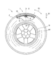
- FIG. 1 is a side view of a tire according to an embodiment of the present disclosure
- FIG. FIG. 2 is a partial cross-sectional view of the tire, showing a cross section taken along the cutting plane II--II in FIG.
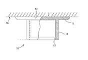
- FIG. 3A is a schematic diagram showing an example of a mount member attached to the tire.
- FIG. 3B is a schematic diagram showing an example of a mount member attached to the tire.
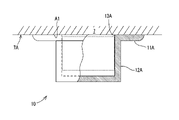
- FIG. 4A is a schematic diagram showing another example of the mount member attached to the tire.
- FIG. 4B is a schematic diagram showing another example of the mount member attached to the tire.
- FIG. 1 is a side view of a pneumatic tire 1 (hereinafter abbreviated as "tire 1") according to an embodiment of the present disclosure.
- FIG. 2 is a cross-sectional view of the tire 1 and shows a cross section taken along the cutting plane II-II in FIG.
- FIG. 1 partially shows the cross-sectional structure of the equatorial plane CL (see FIG. 2).
- 1 and 2 is the radial direction D2 of the tire 1.
- As shown in FIG. 2 is the width direction D1 of the tire 1.
- An arrow D3 shown in FIG. 1 indicates the circumferential direction of the tire 1.
- the tire 1 is mainly composed of a rubber material and is mainly used by being mounted on a vehicle such as an automobile. As shown in FIGS. 1 and 2, the tire 1 is mounted on the rim 30R of the wheel 30. As shown in FIG. The rim 30R is a regular rim, which will be described later.
- the tire 1 is a pneumatic tire in which a hollow portion between the rim 30R and the inner surface 7A of the tire 1 is filled with air. The internal pressure inside the tire 1 is adjusted to a normal internal pressure, which will be described later.
- the state in which the internal pressure of the tire 1 assembled on the rim 30R is adjusted to the normal internal pressure and no load is applied to the tire 1 is referred to as the normal state.
- 1 and 2 show the tire 1 in the normal state mounted on the wheel 30.
- FIG. In this embodiment, unless otherwise specified, the shape of the tire 1 and its parts is the shape in the normal state, and the dimensions and angles of the tire 1 and its parts are measured in the normal state.
- the regular rim is a rim defined by the standards on which the tire 1 relies.
- the regular rim is a "standard rim” in the standards (JATMA standards) defined by JATMA (Japan Automobile Tire Manufacturers Association), and the standards defined by the United States TRA (The Tire and Rim Association) (TRA standard), and "Measuring Rim” in the standard (ETRTO standard) defined by ETRTO (European Tire Rim Technical Organization).
- the regular internal pressure is the internal pressure defined in the standard on which the tire 1 relies. Specifically, the regular pressure is the "maximum air pressure" in the JATMA standard, the “maximum value” indicated in the “TIRE LOAD LIMITS AT VARIOUS COLD INFLATION PRESSURES" in the TRA standard, and the “INFLATION PRESSURE” in the ETRTO standard. ”.
- the tire 1 according to this embodiment is suitably used as a radial tire for automobiles.
- the tire 1 is a pneumatic tire used for vehicles, and is not limited to automobiles, passenger cars, large vehicles such as trucks and buses, motorcycles, competition vehicles, industrial vehicles, special vehicles, trailers and trucks. It may be a pneumatic tire used in a wide variety of vehicles such as heavy duty vehicles.
- the tire 1 is not limited to a radial tire, and can also be suitably used as a bias tire.
- the tire 1 is suitably used as a tire for a passenger car equipped with various electric devices such as a sensor and requiring high convenience and low noise during high-speed running.
- the passenger car tire is a tire mounted on a four-wheeled vehicle and has a maximum load capacity of 1000 kg or less.
- the maximum load capacity is not particularly limited as long as it is 1000 kg or less, but generally, as the maximum load capacity increases, the tire weight tends to increase, and the vibration generated in the tread portion 2 of the tire 1 increases, resulting in increased vibration during running. noise tends to increase, the maximum load capacity is preferably 900 Kg or less, more preferably 800 Kg or less, and further preferably 700 Kg or less.
- the tire weight of the tire 1 is preferably 20 kg or less, more preferably 15 kg or less, further preferably 12 kg or less, 10 kg or less, or 8 kg or less from the viewpoint of reducing vibration in the tread portion 2. preferable.
- the weight of the tire includes the weight of the electric device and the mount member 10, which will be described later, and also includes the weight of sealant, sponge, etc., if provided in the inner cavity of the tire 1.
- the tire 1 includes a tread portion 2, a pair of shoulder portions 3 located at both ends in the width direction D1 of the tread portion 2, and a center direction D21 from the shoulder portions 3 to the center axis of the tire 1. It includes a pair of sidewall portions 4 extending (toward the inside in the radial direction D2) and a pair of bead portions 5 located at the end portions of the sidewall portions 4 on the center direction D21 side.
- the tire 1 includes a carcass 6 (an example of the carcass portion of the present disclosure) extending from the tread portion 2 to the bead core 5A of the bead portion 5 via the shoulder portion 3 and the sidewall portion 4, and an inner A liner 7, a belt portion 8 and a band portion 9 arranged inside the tread portion 2 in the radial direction D2, a mount member 10 attached to the inner surface 7A of the tire 1 (that is, the inner surface 7A of the inner liner 7), Prepare.
- a carcass 6 an example of the carcass portion of the present disclosure
- the tread portion 2 is the portion that comes into contact with the road surface when the vehicle is running.
- the tread portion 2 is composed of a tread rubber 2A made of a vulcanized rubber composition (vulcanized rubber).
- the outer surface of the tread portion 2 is a tread surface 21 (an example of a tire surface) which is a contact surface with the road surface.
- the tread surface 21 is a generally flat surface in the width direction D1. That is, in the tire 1, the tread portion 2 is formed in a flat shape with respect to the width direction D1.
- the rubber composition constituting the tread rubber 2A includes, in addition to rubber components, fillers (reinforcing agents) such as carbon black and silica, oils, resins such as phenolic resins, processing aids, stearic acid, zinc oxide, sulfur, Contains additives such as vulcanization accelerators.
- fillers such as carbon black and silica
- oils such as phenolic resins
- processing aids such as stearic acid
- zinc oxide such as sulfur
- sulfur Contains additives such as vulcanization accelerators.
- rubber component general rubber materials can be used. Rubber, acrylonitrile-butadiene rubber (NBR), acrylonitrile-styrene-butadiene rubber, chloroprene rubber (CR), chlorosulfonated polyethylene, and the like are examples of the rubber material.
- isoprene-based rubber include natural rubber (NR), epoxidized natural rubber (ENR), isoprene rubber (IR), modified NR, modified NR, modified IR, and the like.
- any one kind of the rubber material may be used singly, or two or more kinds of the rubber materials may be mixed at a predetermined compounding ratio and used.
- a tread pattern is formed on the tread surface 21 to exhibit each tire performance such as grip performance, braking performance, drainage function, and wear suppression.
- the tread pattern is formed by a plurality of grooves formed on the tread surface 21 .
- a plurality of main grooves 22 (an example of circumferential grooves of the present disclosure) continuously extending in the circumferential direction D3 (see FIG. 1) of the tire 1 are formed as the concave grooves on the tread surface 21 .
- a plurality of lug grooves (not shown) intersecting with the main groove 22 and a plurality of sipes narrower and shallower than the main groove 22 and the lug grooves may be formed on the tread surface 21 .
- the concave groove referred to herein refers to a groove having a groove width of more than 2.0 mm and a groove depth of more than 5.0 mm.
- the tread pattern formed on the tread surface 21 may be a so-called rib-type pattern having a plurality of main grooves 22 or a so-called rig-lug pattern having the main grooves 22 and the lug grooves.
- the tread portion 2 of the tire 1 is not limited to having any one of the above patterns formed on the tread surface 21 .
- the tread portion 2 may have a so-called lug-shaped pattern having mainly the lug grooves formed on the tread surface 21, or a so-called block-shaped pattern having independent blocks formed on the tread surface 21. may have been Further, the tread pattern may be asymmetric with respect to the width direction of the ground contact surface.
- the tread pattern formed on the tread surface 21 is symmetrical in the width direction D1 with respect to the equatorial plane CL1.
- four main grooves 22 are formed in the tread surface 21 along the circumferential direction D3.
- the four main grooves 22 are arranged at predetermined intervals in the width direction D1 of the tire 1, and two main grooves are arranged in each region of the tread surface 21 outside the equatorial plane CL1 in the width direction D1. . Therefore, the tread portion 2 has five land portions 24 divided in the width direction D1 by four main grooves 22 extending along the circumferential direction D3.
- each main groove 22 may be asymmetric with respect to the width direction D1.
- the number of main grooves 22 is not limited to four, and may be less than four or five or more.
- any one of the main grooves 22 may be provided on the equatorial plane CL1.
- the five land portions 24 include one crown land portion 24A, two middle land portions 24B, and two shoulder land portions 24C.
- the shoulder land portion 24C is arranged in the vicinity of the shoulder portion 3, and is located between both side end portions of the tread portion 2 in the width direction D1 and the two second main grooves 22B arranged on the outermost side in the width direction D1. divided between.
- the middle land portion 24B is divided between two first main grooves 22A and two second main grooves 22B arranged near the equatorial plane CL1.
- the crown land portion 24A is arranged in the center portion of the tread portion 2 of the tire 1 in the width direction D1.
- the crown land portion 24A is arranged at a portion of the tread portion 2 that intersects with the equatorial plane CL1.
- the crown land portion 24A occupies a region of the tread portion 2 that is spaced apart from the intersection with the equatorial plane CL1 in the width direction D1 by a predetermined distance.
- the area is centered on the equatorial plane CL1 and has a ratio determined within a range of 10 to 50% with respect to the contact width of the contact surface of the tread portion 2 .
- the ratio is preferably 30%, more preferably 20%.
- the crown land portion 24A is provided in a region of the tread portion 2 that is divided between the two first main grooves 22A.
- the crown land portion 24A is a portion divided between two first main grooves 22A.
- the crown land portion 24A may extend linearly along the circumferential direction D3, or may extend in a zigzag shape. Also, the crown land portion 24A may extend obliquely in the circumferential direction D3, or may extend in a curved or arcuate shape.
- Each of the two first main grooves 22A positioned on both sides in the width direction D1 is linear, zigzag, inclined, or curved along the circumferential direction D3 so that the crown land portion 24A has the shape described above. , or formed to extend in an arc.
- the crown land portion 24A may have a plurality of blocks divided in the circumferential direction D3 by lateral grooves such as the lug grooves or inclined grooves, or may have a plurality of blocks divided in the circumferential direction D3 by lateral grooves such as the sipes or inclined grooves. It may have a plurality of semi-blocks divided into.
- the land portions 24 other than the crown land portion 24A also extend along the circumferential direction D3 and are formed in the same shape as the crown land portion 24A.
- the groove width of the first main groove 22A is, for example, 4.0% to 7.0% of the width of the tread portion 2.
- the groove width of the second main groove 22B is, for example, 2.5% to 4.5% of the width of the tread portion 2.
- the groove depths of the first main groove 22A and the second main groove 22B are, for example, 5 to 10 mm.
- the shoulder portion 3 is a portion corresponding to the corner portion of the tire 1 from the tread portion 2 to the sidewall portion 4 .
- the shoulder portion 3 is a portion that connects the tread portion 2 and the sidewall portion 4, and is formed in a round shape (curved shape) from the end portion of the tread portion 2 in the width direction D1 to the upper end portion of the sidewall portion 4. ing.
- the sidewall portion 4 is composed of a vulcanized rubber composition (vulcanized rubber).
- the sidewall portion 4 is arranged outside the carcass 6 in the width direction D1.
- the sidewall portion 4 is connected to the end portion of the tread rubber 2A forming the tread portion 2 in the width direction D1 and extends along the carcass 6 in the center direction D21. A carcass 6 on the side of the tire 1 is protected by the sidewall portion 4 .
- the carcass 6 is arranged inside the tread portion 2 and the pair of sidewall portions 4 and closer to the tread portion 2 and the sidewall portions 4 than the inner liner 7 is.
- the carcass 6 is composed of at least one carcass ply.
- the carcass ply is a cord layer having a large number of carcass cords (not shown) extending in a direction crossing the equatorial plane CL1 of the tire 1 .
- the carcass ply is obtained by covering these carcass cords with a topping rubber made of a predetermined rubber composition (vulcanized rubber).
- a large number of carcass cords are arranged along the circumferential direction D3 of the tire 1 while crossing the equatorial plane CL1 of the tire 1 at a predetermined angle (for example, an angle defined within a range of 70 to 90 degrees). are arranged in this way.
- the carcass cords for example, cords made of organic fibers such as nylon fibers, polyester fibers, rayon fibers and aramid fibers (hereinafter referred to as "organic fiber cords”) are used.
- the inner liner 7 is provided inside the carcass 6 and forms an inner surface 7A of the tire 1 .
- the inner liner 7 is made of a rubber composition (vulcanized rubber) having air barrier properties, and plays a role of maintaining the internal pressure of the tire 1 .
- the inner liner 7 is attached to the inner surface of the carcass 6 .
- the inner liner 7 may be directly bonded to the carcass 6, or may be bonded to an insulation layer arranged radially inward of the carcass 2. As shown in FIG.
- the rubber composition (second rubber composition) constituting the inner liner 7 includes, in addition to the rubber component, a filler (reinforcing agent) such as carbon black, oil, resins such as phenol resin, processing aids, stearic acid, Contains additives such as zinc oxide, sulfur and vulcanization accelerators.
- a filler such as carbon black, oil, resins such as phenol resin, processing aids, stearic acid, Contains additives such as zinc oxide, sulfur and vulcanization accelerators.
- a rubber material mainly composed of butyl-based rubber, which has excellent resistance to air permeability can be used.
- the butyl rubber include butyl rubber (IIR), brominated butyl rubber (BR-IIR), halogenated butyl rubber (X-IIR) such as chlorinated butyl rubber (Cl-IIR), and isobutylene and p-alkylstyrene.
- IIR butyl rubber
- BR-IIR brominated butyl rubber
- X-IIR halogenated butyl rubber
- chlorinated butyl rubber Cl-IIR
- isobutylene and p-alkylstyrene examples thereof include polymers, halides of the copolymers, and the like.
- halogenated butyl rubber is preferred, and brominated butyl rubber and chlorinated butyl rubber are more preferred, from the viewpoint that sheet processability and air barrier properties can be improved in a well-balanced manner.
- any one type of butyl-based rubber may be used singly, or two or more types of rubber materials may be mixed at a predetermined blending ratio and used. It is also possible to apply a viscoelastic body mainly composed of a plastic elastomer having a low air permeability as the rubber composition forming the inner liner 7 .
- butyl-based rubber it is preferable to use recycled butyl-based rubber in combination with normal butyl-based rubber (butyl-based rubber other than recycled butyl-based rubber).
- Recycled butyl rubber usually has a high content of non-halogenated butyl rubber (regular butyl rubber), so when used in combination with halogenated butyl rubber, good air barrier properties and vulcanization speed can be ensured.
- the total content of butyl rubber in 100% by mass of the rubber component is 70% by mass or more, preferably 75% by mass or more, more preferably 80% by mass or more. If it is less than 70% by mass, there is a risk that sufficient air barrier properties cannot be obtained.
- the total content may be 100% by mass, but is preferably 95% by mass or less, more preferably 90% by mass or less, from the viewpoint of sheet processability and air barrier properties.
- the content of the recycled butyl rubber in 100% by mass of the rubber component is preferably 5% by mass or more, more preferably 8% by mass or more. If it is less than 5% by mass, there is a risk that the merits of using the reclaimed butyl-based rubber cannot be sufficiently obtained.
- the content is preferably 30% by mass or less, more preferably 25% by mass or less. If it exceeds 30% by mass, there is a risk that sufficient air barrier properties and vulcanization speed cannot be ensured.
- the rubber composition that constitutes the inner liner 7 preferably contains isoprene-based rubber from the viewpoint that sheet processability and air barrier properties can be improved in a well-balanced manner.
- isoprene-based rubber examples include natural rubber (NR), epoxidized natural rubber (ENR), and isoprene rubber (IR).
- NR and IR are preferable because they can improve sheet processability and air barrier properties in a well-balanced manner.
- NR is not particularly limited, and for example, those commonly used in the tire industry, such as SIR20, RSS#3, and TSR20, can be used.
- IR is not particularly limited, and one commonly used in the tire industry can be used.
- the content of isoprene-based rubber in 100% by mass of the rubber component is preferably 5% by mass or more, more preferably 10% by mass or more. If it is less than 5% by mass, it may not be possible to obtain a good balance between sheet processability and air barrier properties.
- the content is preferably 30% by mass or less, more preferably 25% by mass or less. If it exceeds 30% by mass, the vulcanized rubber may not have sufficient air barrier properties.
- the rubber component contained in the rubber composition forming the inner liner 7 may contain other rubber materials in addition to the butyl-based rubber and the isoprene-based rubber.
- examples include diene rubbers such as butadiene rubber (BR), styrene butadiene rubber (SBR), ethylene propylene diene rubber (EPDM), styrene isoprene butadiene rubber (SIBR), chloroprene rubber (CR), and acrylonitrile butadiene rubber (NBR). be done. Any one of these rubber materials may be used alone as the rubber component, or two or more rubber materials may be used by mixing them in a predetermined mixing ratio. good.
- the rubber composition that constitutes the inner liner 7 preferably contains a filler.
- specific fillers include carbon black, silica, calcium carbonate, talc, alumina, clay, aluminum hydroxide, and mica.
- carbon black and silica are preferably used as reinforcing agents. It is preferable to use these together.
- silica it is preferable to use together with a silane coupling agent.
- the carbon black is not particularly limited, and includes N134, N110, N220, N234, N219, N339, N330, N326, N351, N550, N762 and the like. These may be used independently and may be used in combination of 2 or more type.
- Examples of the carbon black include Asahi Carbon Co., Ltd., Cabot Japan Co., Ltd., Tokai Carbon Co., Ltd., Mitsubishi Chemical Co., Ltd., Lion Corporation, Shin Nikka Carbon Co., Ltd., Columbia Carbon Co., Ltd. product can be used.
- the content of the carbon black is preferably 1 part by mass or more, more preferably 3 parts by mass or more, and preferably 50 parts by mass or less, more preferably 30 parts by mass or less, relative to 100 parts by mass of the rubber component. and more preferably 10 parts by mass or less.
- the rubber composition forming the inner liner 7 preferably contains a plasticizer (softener).
- a plasticizer softener
- the plasticizer include resin components, oils, liquid rubbers, ester plasticizers, and the like. These may be used independently and may be used in combination of 2 or more type.
- the plasticizer is preferably an oil or resin component.
- the oil is not particularly limited as long as it is commonly used in the tire industry, and includes process oil, vegetable oil, and mixtures thereof.
- process oil for example, paraffinic process oil, aromatic process oil, naphthenic process oil, etc. can be used.
- Vegetable oils include castor oil, cottonseed oil, linseed oil, rapeseed oil, soybean oil, palm oil, coconut oil, peanut oil, rosin, pine oil, pine tar, tall oil, corn oil, rice bran oil, safflower oil, sesame oil, Olive oil, sunflower oil, palm kernel oil, camellia oil, jojoba oil, macadamia nut oil, tung oil and the like. These may be used independently and may be used in combination of 2 or more type. Process oils are particularly preferred, and aromatic process oils are more preferred.
- Examples of the oil include Idemitsu Kosan Co., Ltd., Sankyo Yuka Kogyo Co., Ltd., ENEOS Co., Ltd., Orisoi, H&R, Toyokuni Oil Co., Ltd., Showa Shell Oil Co., Ltd., Fuji Kosan Co., Ltd. etc. products can be used.
- the rubber composition that constitutes the inner liner 7 preferably contains a resin component as necessary.
- the resin component may be solid or liquid at room temperature, and specific resin components include styrene-based resins, coumarone-based resins, terpene-based resins, C5 resins, C9 resins, C5C9 resins, and acrylic resins. system resin and the like. These may be used independently and may be used in combination of 2 or more type.
- the content of the resin component is more than 2% by mass, preferably less than 45% by mass, more preferably less than 30% by mass, relative to 100% by mass of the rubber component.
- a styrene-based resin is a polymer using a styrene-based monomer as a constituent monomer, and examples thereof include polymers polymerized with a styrene-based monomer as a main component (50% by mass or more).
- styrene monomers styrene, o-methylstyrene, m-methylstyrene, p-methylstyrene, ⁇ -methylstyrene, p-methoxystyrene, p-tert-butylstyrene, p-phenylstyrene, o-Chlorostyrene, m-chlorostyrene, p-chlorostyrene, etc.), homopolymers obtained by polymerizing each alone, copolymers obtained by copolymerizing two or more styrene monomers, and styrene monomers and copolymers of other monomers copolymerizable therewith.
- styrene monomers styrene, o-methylstyrene, m-methylstyrene, p-methylstyrene, ⁇ -methylstyrene, p-methoxyst
- Examples of the other monomers include acrylonitrile and methacrylonitrile, acrylics, unsaturated carboxylic acids such as methacrylic acid, unsaturated carboxylic acid esters such as methyl acrylate and methyl methacrylate, chloroprene, and butadiene.
- Examples include dienes such as isoprene, olefins such as 1-butene and 1-pentene; ⁇ , ⁇ -unsaturated carboxylic acids such as maleic anhydride and acid anhydrides thereof.
- a coumarone-indene resin is preferably used as the coumarone-based resin.
- a coumarone-indene resin is a resin containing coumarone and indene as monomer components constituting the skeleton (main chain) of the resin. Examples of monomer components contained in the skeleton other than coumarone and indene include styrene, ⁇ -methylstyrene, methylindene, and vinyltoluene.
- the content of the coumarone-indene resin is, for example, more than 1.0 parts by mass and less than 50.0 parts by mass with respect to 100 parts by mass of the rubber component.
- the hydroxyl value (OH value) of the coumarone-indene resin is, for example, more than 15 mgKOH/g and less than 150 mgKOH/g.
- the OH value is the amount of potassium hydroxide required to neutralize the acetic acid bound to the hydroxyl group when acetylating 1 g of the resin, expressed in milligrams, and is determined by the potentiometric titration method (JIS K 0070: 1992).
- the softening point of the coumarone-indene resin is, for example, more than 30°C and less than 160°C.
- the softening point is the temperature at which the ball descends when the softening point specified in JIS K 6220-1:2001 is measured with a ring and ball type softening point measuring device.
- terpene-based resins include polyterpene, terpenephenol, and aromatic modified terpene resins.
- Polyterpenes are resins obtained by polymerizing terpene compounds and hydrogenated products thereof.
- Terpene compounds are hydrocarbons represented by the composition (C 5 H 8 ) n and their oxygen-containing derivatives, such as monoterpene (C 10 H 16 ), sesquiterpene (C 15 H 24 ), diterpene (C 20 H 32 ) and the like, which are compounds having a terpene as a basic skeleton, such as ⁇ -pinene, ⁇ -pinene, dipentene, limonene, myrcene, alloocimene, ocimene, ⁇ -phellandrene, ⁇ -terpinene, ⁇ -terpinene, terpinolene , 1,8-cineole, 1,4-cineole, ⁇ -terpineol, ⁇ -terpin
- polyterpenes examples include terpene resins such as ⁇ -pinene resin, ⁇ -pinene resin, limonene resin, dipentene resin, ⁇ -pinene/limonene resin made from the above-described terpene compounds, and hydrogen obtained by hydrogenating the terpene resin.
- Additive terpene resins are also included.
- the terpene phenol include a resin obtained by copolymerizing the terpene compound and a phenolic compound, and a resin obtained by hydrogenating the resin. Specifically, the terpene compound, the phenolic compound and formalin are condensed. resin.
- phenolic compounds include phenol, bisphenol A, cresol, and xylenol.
- aromatic modified terpene resins include resins obtained by modifying terpene resins with aromatic compounds, and resins obtained by hydrogenating the resins.
- the aromatic compound is not particularly limited as long as it is a compound having an aromatic ring. Examples include phenol compounds such as phenol, alkylphenol, alkoxyphenol, unsaturated hydrocarbon group-containing phenol; naphthol compounds such as unsaturated hydrocarbon group-containing naphthol; styrene derivatives such as styrene, alkylstyrene, alkoxystyrene, unsaturated hydrocarbon group-containing styrene; coumarone, indene, and the like.
- C5 resin refers to a resin obtained by polymerizing a C5 fraction.
- C5 fractions include petroleum fractions having 4 to 5 carbon atoms such as cyclopentadiene, pentene, pentadiene and isoprene.
- Dicyclopentadiene resin DCPD resin
- DCPD resin Dicyclopentadiene resin
- C9 resin refers to a resin obtained by polymerizing a C9 fraction, and may be hydrogenated or modified.
- C9 fractions include petroleum fractions having 8 to 10 carbon atoms such as vinyltoluene, alkylstyrene, indene, and methylindene.
- coumarone-indene resin, coumarone resin, indene resin, and aromatic vinyl resin are preferably used.
- aromatic vinyl resin ⁇ -methylstyrene, homopolymers of styrene, or copolymers of ⁇ -methylstyrene and styrene are preferable because they are economical, easy to process, and have excellent heat build-up properties. , a copolymer of ⁇ -methylstyrene and styrene is more preferred.
- the aromatic vinyl resin for example, those commercially available from Kraton Co., Eastman Chemical Co., etc. can be used.
- C5C9 resin refers to a resin obtained by copolymerizing the C5 fraction and the C9 fraction, and may be hydrogenated or modified.
- the C5 fraction and C9 fraction include the aforementioned petroleum fractions.
- As the C5C9 resin for example, those commercially available from Tosoh Corporation, LUHUA, etc. can be used.
- acrylic resin is not particularly limited, for example, a solvent-free acrylic resin can be used.
- Solvent-free acrylic resin can be produced by a high-temperature continuous polymerization method (high-temperature continuous bulk polymerization method) (U.S. Pat. No. 4,414,370) without using auxiliary materials such as polymerization initiators, chain transfer agents, organic solvents, etc. as much as possible.
- high-temperature continuous bulk polymerization method U.S. Pat. No. 4,414,370
- auxiliary materials such as polymerization initiators, chain transfer agents, organic solvents, etc.
- (meth)acryl means methacryl and acryl.
- Examples of monomer components constituting the acrylic resin include (meth)acrylic acid, (meth)acrylic acid esters (alkyl esters, aryl esters, aralkyl esters, etc.), (meth)acrylamides, and (meth)acrylamide derivatives.
- (Meth)acrylic acid derivatives such as
- styrene In addition to (meth)acrylic acid and (meth)acrylic acid derivatives, styrene, ⁇ -methylstyrene, vinyltoluene, vinylnaphthalene, divinylbenzene, trivinylbenzene, divinylnaphthalene, etc., may be used as monomer components constituting the acrylic resin. of aromatic vinyls may be used.
- the acrylic resin may be a resin composed only of a (meth)acrylic component, or a resin containing components other than the (meth)acrylic component as constituent elements. Moreover, the acrylic resin may have a hydroxyl group, a carboxyl group, a silanol group, or the like.
- Examples of the resin component include Maruzen Petrochemical Co., Ltd., Sumitomo Bakelite Co., Ltd., Yasuhara Chemical Co., Ltd., Tosoh Corporation, Rutgers Chemicals, BASF, Arizona Chemical, Nichinuri Chemical Co., ( Products of Nippon Shokubai Co., Ltd., ENEOS Co., Ltd., Arakawa Chemical Industry Co., Ltd., Taoka Chemical Industry Co., Ltd., etc. can be used.
- the rubber composition forming the inner liner 7 preferably contains a processing aid.
- the processing aid is not particularly limited as long as it is commonly used in the tire industry. Examples include fatty acid metal salts, fatty acid amides, amide esters, silica surfactants, fatty acid esters, fatty acid metal salts and amides. Mixtures with esters, mixtures of fatty acid metal salts and fatty acid amides, and the like can be used. These may be used alone or in combination of two or more. Among them, fatty acid metal salts, amide esters, mixtures of fatty acid metal salts and amide esters or fatty acid amides are preferred, and mixtures of fatty acid metal salts and fatty acid amides are particularly preferred.
- the fatty acid constituting the fatty acid metal salt is not particularly limited, but saturated or unsaturated fatty acid (preferably saturated or unsaturated fatty acid with 6 to 28 carbon atoms (more preferably 10 to 25 carbon atoms, more preferably 14 to 20 carbon atoms)) unsaturated fatty acids), such as lauric acid, myristic acid, palmitic acid, stearic acid, oleic acid, linoleic acid, linolenic acid, arachidic acid, behenic acid, and nervonic acid. These can be used singly or in combination of two or more. Among them, saturated fatty acids are preferred, and saturated fatty acids having 14 to 20 carbon atoms are more preferred.
- metals constituting fatty acid metal salts include alkali metals such as potassium and sodium, alkaline earth metals such as magnesium, calcium and barium, zinc, nickel and molybdenum. Among them, zinc and calcium are preferred, and zinc is more preferred.
- the fatty acid amide may be saturated fatty acid amide or unsaturated fatty acid amide.
- saturated fatty acid amides include N-(1-oxooctadecyl)sarcosine, stearic acid amide, and behenic acid amide.
- unsaturated fatty acid amides include oleic acid amide and erucic acid amide.
- mixtures of fatty acid metal salts and fatty acid amides include WB16 manufactured by Structol, which is a mixture of fatty acid calcium and fatty acid amides.
- the content of the processing aid is preferably 0.1 parts by mass or more, more preferably 0.5 parts by mass or more, and still more preferably 1 part by mass or more with respect to 100 parts by mass of the rubber component. Also, the content is preferably 10 parts by mass or less, more preferably 5 parts by mass or less.
- Conventionally known stearic acid can be used as the stearic acid contained in the rubber composition that constitutes the inner liner 7.
- NOF Corporation, NOF Corporation, Kao Corporation, FUJIFILM Wako Pure Chemical Industries, Ltd., Chiba Products such as Fatty Acids Co., Ltd. can be used.
- Zinc oxide contained in the rubber composition constituting the inner liner 7 can be conventionally known, for example, Mitsui Kinzoku Co., Ltd., Toho Zinc Co., Ltd., Haku Sui Tech Co., Ltd., Seido Chemical Industry Co., Ltd. ), products of Sakai Chemical Industry Co., Ltd., etc. can be used.
- Sulfur contained in the rubber composition forming the inner liner 7 is not particularly limited as long as it is widely used in the tire industry, and includes powdered sulfur, precipitated sulfur, colloidal sulfur, insoluble sulfur, highly dispersible sulfur, and soluble sulfur. etc. These may be used independently and may be used in combination of 2 or more type.
- sulfur for example, products of Tsurumi Chemical Industry Co., Ltd., Karuizawa Io Co., Ltd., Shikoku Chemical Industry Co., Ltd., Flexis Co., Ltd., Nihon Kantan Kogyo Co., Ltd., Hosoi Chemical Industry Co., Ltd., etc. can be used.
- the vulcanization accelerator contained in the rubber composition constituting the inner liner 7 is not particularly limited as long as it is commonly used in the tire industry, and includes 2-mercaptobenzothiazole, di-2-benzothiazolyl disulfide, and the like.
- thiazole-based vulcanization accelerators tetramethylthiuram disulfide (TMTD), tetrabenzylthiuram disulfide (TBzTD), tetrakis (2-ethylhexyl) thiuram disulfide (TOT-N) and other thiuram-based vulcanization accelerators; N-cyclohexyl- 2-benzothiazolylsulfenamide, Nt-butyl-2-benzothiazolylsulfenamide, N-oxyethylene-2-benzothiazolesulfenamide, N-oxyethylene-2-benzothiazolesulfenamide, Sulfenamide-based vulcanization accelerators such as N,N'-diisopropyl-2-benzothiazolesulfenamide; .
- sulfenamide vulcanization accelerators and thiuram vulcanization accelerators are preferred, and combined use of sulfenamide vulcanization accelerators and thiuram vulcanization accelerators is more preferred.
- vulcanization accelerator for example, products manufactured by Kawaguchi Kagaku Co., Ltd., Ouchi Shinko Kagaku Co., Ltd., Rhein Chemie Co., etc. can be used.
- the inner liner 7 is made of a rubber composition having a complex elastic modulus E * at 70° C. smaller than that of the rubber composition (first rubber composition) of the mount member 10 . That is, the complex elastic modulus E * 2 of the rubber composition forming the inner liner 7 at 70°C is smaller than the complex elastic modulus E * 1 of the rubber composition forming the mount member 10 at 70°C. The effects of such a configuration will be described later.
- the bead portion 5 is a portion that is joined to the wheel, and fixes the tire 1 to the rim 30R by internal pressure.
- the bead portion 5 includes a bead core 5A composed of a plurality of steel bead wires 5C and an apex rubber 5B.
- the apex rubber 5B is located outside the bead core 5A in the radial direction D2, and is made of, for example, a highly rigid rubber composition (vulcanized rubber).
- the bead core 5A and the apex rubber 5B are surrounded on the outside by carcass plies of the carcass 6. As shown in FIG.
- the carcass ply is folded back from the inside in the width direction D1 around the bead core 5A to the outside in the width direction D1, and the outside in the width direction D1 of the bead portion 5 extends outside in the radial direction D2.
- the bead core 5A and the apex rubber 5B are arranged in the portion surrounded by the carcass ply in this way.
- the belt portion 8 is a belt-like member extending in the circumferential direction D3 of the tire 1.
- the belt portion 8 is arranged inside the tread portion 2 in the radial direction D ⁇ b>2 and outside the carcass 6 .
- the belt portion 8 plays a role of tightening the carcass 6 in the radial direction D ⁇ b>2 and increasing the composition of the tread portion 2 .
- the belt portion 8 is also a reinforcing layer that reinforces the carcass 6 together with the band portion 9 described later.
- the belt portion 8 is composed of at least one belt ply 8A. In this embodiment, the belt portion 8 has two belt plies 8A. The belt portion 8 extends around the tire 1 in the circumferential direction D3.
- the belt ply 8A has a large number of belt cords (not shown) extending in a direction intersecting the equatorial plane CL1 of the tire 1.
- the belt ply 8A is obtained by covering these belt cords with a topping rubber.
- a large number of belt cords are arranged along the circumferential direction D3 of the tire 1 while crossing the equatorial plane CL1 of the tire 1 at a predetermined angle (for example, an angle defined within a range of 10 to 35 degrees). are arranged in this way.
- the belt plies 8A are arranged so that the belt cords intersect each other.
- the belt cord for example, a steel cord (steel cord) or the organic fiber cord is used.
- the band portion 9 is a belt-like member extending in the circumferential direction D3 of the tire 1.
- the band portion 9 is arranged inside the tread portion 2 in the radial direction D ⁇ b>2 and outside the belt portion 8 .
- the band portion 9 has a full band 9A covering the entire belt portion 8 and a pair of edge bands 9B provided at positions corresponding to both ends of the tread portion 2 in the width direction D1.
- the band portion 9 restrains the movement of the belt portion 8 and plays a role of preventing the belt portion 8 from lifting or peeling off due to centrifugal force during running of the vehicle.
- the band portion 9 is also a reinforcing layer that reinforces the carcass 6 together with the belt portion 8 described above.
- FIG. 3A and 3B are diagrams showing the configuration of the mount member 10.
- FIG. 3A is a perspective view of the mount member 10
- FIG. 3B is a partial cross-sectional view of the mount member 10.
- the mount member 10 is for mounting electrical devices such as sensors that detect temperature, vibration, pressure, acceleration, etc., and is fixed to the inner surface 7A of the tire 1, that is, the inner surface 7A of the inner liner 7.
- Examples of the electric device include, in addition to the sensor, a repeater for relaying wireless communication, a transmitter for transmitting a predetermined signal, and the like.
- the mount member 10 has a mounting seat portion 11 fixed to the inner surface 7A, and a main body portion 12 detachably mounting the electrical device.
- the mount member 10 is formed by integrally forming a mounting seat portion 11 and a main body portion 12 with a vulcanized rubber composition (vulcanized rubber).
- a vulcanized rubber composition vulcanized rubber
- the portion indicated by the dotted line in FIG. 3B indicates the electric device mounted on the mount member 10. As shown in FIG.
- the mount member 10 is composed of a rubber composition different from that of the inner liner 7.
- a material other than the rubber component blended in the rubber composition of the mount member 10 a material common to the rubber composition of the inner liner 7 can be used.
- the rubber composition forming the mount member 10 may contain additives such as reinforcing agents such as carbon black and silica, anti-aging agents, vulcanization accelerators, and plasticizers, in addition to rubber components.
- the rubber component forming the mount member 10 may be the same as the rubber component of the inner liner 7, or may be different. That is, the rubber component of the mount member 10 may be any one of the above-mentioned types of rubber materials applicable as the rubber component of the inner liner 7, or may be two rubber materials.
- the rubber component of the mount member 10 is a rubber component different from that of the inner liner 7, for example, butadiene rubber (BR) having a low glass transition temperature Tg and excellent low temperature characteristics, and acrylonitrile butadiene rubber (NBR) having excellent mechanical characteristics. It may be a rubber component mainly containing and.
- the rubber component of the mount member 10 may be other rubber materials such as isoprene rubber, styrene butadiene rubber (SBR), styrene isoprene rubber, styrene isoprene butadiene rubber (SIBR), and diene rubber such as chloroprene rubber (CR).
- the mount member 10 may be made of the same rubber component as the inner liner 7 .
- the mounting seat portion 11 is formed, for example, in a disc shape, and its outer diameter is formed larger than the outer diameter of the main body portion 12 . Further, the main body portion 12 is formed in a cylindrical shape protruding from one board surface of the mounting seat portion 11 . An opening 13 communicating with the inside is formed in the protruding end face of the body portion 12, and the electric device is fitted into the body portion 12 through the opening 13 and held by the elasticity of rubber. Various methods can be adopted as a method of attaching the attachment seat portion 11 to the inner surface 7A of the tire 1 .
- the attachment area A1 (attachment surface) of the inner surface 7A is subjected to a predetermined surface treatment to remove the skin of the attachment area A1, and then the attachment seat portion 11 of the mount member 10 is welded to the attachment area A1, or adhesive is applied to the attachment area A1. It is possible to apply a mounting method that adheres and fixes with .
- the surface processing treatment the surface of the mounting area A1 on the inner surface 7A is polished with a polishing machine to remove the release agent together with the skin, or the surface of the mounting area A1 is irradiated with a laser beam to remove the mounting area A1.
- a treatment for removing the skin on the surface together with a release agent may be considered.
- the surface processing process is a process of processing the surface of the attachment area A1 into a uniform surface (for example, a flat surface) by polishing with a polishing machine or by irradiating the laser beam.
- a uniform surface for example, a flat surface
- the adhesion between the mounting area A1 and the contact surface of the mounting seat portion 11 is improved, and the mounting strength of the mount member 10 in the mounting area A1 can be improved.
- the release agent adhering to the attachment area A1 is also removed, it is possible to prevent a decrease in strength caused by the release agent, and to more firmly attach the mount member 10 to the attachment area A1.
- the bonding surface of the mounting seat portion 11 is also subjected to the surface treatment by polishing with a polishing machine or laser light irradiation before mounting the mounting member 10 .
- the adhesiveness of the adhesive surface of the mounting seat portion 11 to the mounting area A1 is further enhanced, and the mounting strength of the mount member 10 can be further improved.
- the tire 1 is vulcanized without applying the release agent to the mounting region A1 from the beginning, and then the mounting seat portion 11 is mounted on the mounting region A1.
- the mount member 10 is fixed by welding or by bonding with an adhesive, or by joining the mounting seat portion 11 to the inner surface 7A of the tire 1 before vulcanization and then vulcanizing the tire 1 together with the mount member 10. is fixed to the inner surface 7A.
- the surface processing treatment is preferably a processing treatment using laser light irradiation, which can uniformly process the surface of the mounting area A1 or the contact surface of the mounting seat portion 11 with high accuracy. Further, according to the processing by laser beam irradiation, the step at the boundary between the processed portion (surface-processed surface) and the unprocessed portion (unprocessed surface) can be set to 200 ⁇ m or less.
- the amount of scraping of the epidermis can be reduced compared to processing by polishing.
- the boundary between the portion where the surface processing treatment was performed (surface processed surface) and the portion where the surface processing treatment was not performed (unprocessed surface) It is considered that the determination can be made by confirming whether or not the step of the portion is 200 ⁇ m or less. In other words, if the step at the boundary is 200 ⁇ m or less, it can be determined that the surface processing by the laser beam has been performed, and if the step at the boundary is greater than 200 ⁇ m, it can be determined that another surface processing has been performed. It is considered possible.
- the mount member 10 may have elasticity capable of holding the electronic device, and the complex elastic modulus E * at 70° C. of the rubber composition of the mount member 10 is preferably 4.5 MPa, for example.
- the mount member 10 is arranged on the inner surface 7A of the tire 1 at a position corresponding to the central portion of the tread portion 2 in the width direction D1.
- the mount member 10 is arranged on the inner surface 7A of the tire 1 at a position corresponding to the above-described crown land portion 24A.
- the mount member 10 is arranged on the inner surface 7A of the tire 1 in a mounting area A1 (mounting position) corresponding to the crown land portion 24A described above.
- the mounting area A1 passes through both ends in the width direction D1 forming the ground contact surface of the crown land portion 24A and is perpendicular to the tread surface profile obtained by virtually connecting the surfaces of the crown land portion 24A. It is a region on the inner surface 7A separated by the straight line L1. In other words, the mounting region A1 is surrounded by two intersections P1 and P1 where two straight lines L1 parallel to the equatorial plane CL1 and the inner surface 7A intersect on the back surface (inner surface) of the tread portion 2. area.
- the straight line L1 is a straight line parallel to the equatorial plane CL1 passing through both ends of the crown land portion 24A in the width direction D1.
- the position corresponding to the crown land portion 24A means a position arranged so that the center of the mounting seat portion 11 of the mount member 10 is within the mounting area A1, passing through the center of the crown land portion 24A.
- the position is not limited to the position where the straight line (the straight line included in the equatorial plane CL1) and the center of the mount member 10 match.
- the attachment area A1 may be an area corresponding to both or either one of the two middle land portions 24B.
- the mounting area A1 passes through both ends in the width direction D1 forming the ground contact surface of the middle land portion 24B, and is perpendicular to the tread surface profile obtained by virtually connecting the surfaces of the middle land portion 24B. It is a region on the inner surface 7A separated by two straight lines L2. Also, the attachment region A1 may be a region corresponding to both or either one of the two shoulder land portions 24C.
- the attachment region A1 includes a straight line L31 passing through the end of the ground contact surface of the tread surface 21 in the width direction D1 and perpendicular to the tread surface profile, and the end of the shoulder land portion 24C on the side of the second main groove 22B. the area on the inner surface 7A bounded by L32 through the tread surface profile and perpendicular to the tread surface profile.
- the mount member 10 is provided at a position where a straight line passing through the center of the crown land portion 24A (a straight line included in the equatorial plane CL1) and the center of the mount member 10 coincide. More specifically, the center of the mounting seat portion 11 of the mount member 10 is aligned with a straight line (a straight line included in the equatorial plane CL1) passing through the center of the crown land portion 24A and the center of the tire 1 in the cross-sectional view of FIG. It is fixed to the inner surface 7A so as to coincide with the intersection with 7A. Therefore, the mount member 10 is not arranged at a position corresponding to the main groove 22 formed in the tread portion 2 on the inner surface 7A. That is, the mount member 10 is not provided on the back side of the main groove 22 in the tread portion 2 .
- the center of the mounting seat portion 11 is located within a region divided by a line perpendicular to the tread surface profile at a position 50% of the contact width of the contact surface of the tread portion 2 around the equatorial plane CL1. It is desirable to have This is because it is considered that if the area is outside 50% in the width direction D1, the amount of deformation of the tread portion 2 during rolling is large, and the vibration noise of the mount member 10 is also large.
- the tread surface profile is a surface shape that can be obtained by virtually connecting the surfaces of the land portions 24 in the normal state.
- the contact width is the maximum position in the width direction of the contact patch obtained when the tire 1 is pressed against a smooth road surface with the normal internal pressure, normal load, and camber angle of 0 degrees.
- the normal load is the load defined in the standard on which the tire 1 relies. Specifically, the normal load is the "maximum load capacity" in the JATMA standard, the "maximum value” indicated in “TIRE LOAD LIMITS AT VARIOUS COLD INFLATION PRESSURES" in the TRA standard, and the "LOAD CAPACITY ”.
- the mount member 10 including the mounting seat portion 11 is exemplified, but the mounting member 10 may not include the mounting seat portion 11 and may be composed only of the main body portion 12. .
- the mount members 10 are arranged at regular intervals along the circumferential direction D3 on the inner surface 7A. Thereby, when a plurality of mount members 10 are provided, the weight balance in the circumferential direction D3 can be maintained evenly.
- the mounting position of the mount member 10 is not limited to the mounting area A1.
- the mount member 10 may be mounted on the inner surface 7A of the tire 1 at a position corresponding to either one of the two middle land portions 24B.
- the mount member 10 may be attached at positions corresponding to both of the two middle land portions 24B.
- both of the two middle land portions 24B equally spaced in the width direction D1 by the equatorial plane CL1 of the tire 1 are supported. It is preferably mounted in position. At this time, if the crown land portion 24A exists on the equatorial plane CL1, each mount member 10 may be attached at a position corresponding to the crown land portion 24A. In this case, the weight balance in the width direction D1 can be made symmetrical about the equatorial plane CL1 and kept even.
- the mount member 10 may be of any shape as long as it can be mounted with an electrical device, and may be formed, for example, as shown in FIGS. 4A and 4B.
- FIGS. 4A and 4B are diagrams showing another configuration of the mount member 10, FIG. 4A being a perspective view of the mount member 10, and FIG. 4B being a partial sectional view of the mount member 10.
- FIG. The mount member 10 shown in FIGS. 4A and 4B has an annular mounting seat portion 11A and a cylindrical main body portion 12A having an inner hole continuous to an opening 13A of the mounting seat portion 11A. The other side of the body portion 12A is closed. Therefore, when the mounting seat portion 11A is fixed to the inner surface 7A in a state in which the electrical equipment is held inside the main body portion 12A, the electrical equipment is sealed from the outside.
- the mount member 10 to which the electrical equipment is mounted is provided on the inner surface 7A of the tire 1, vibration transmitted from the road surface to the tire 1 propagates through the tread portion 2 while the vehicle is running, causing the mount member 10 and the electric device to move. There is a possibility that the electrical equipment inside the tire 1 may vibrate. Moreover, the mount member 10 periodically abuts the road surface via the tread portion 2 each time the tire 1 makes one revolution, and the load of the mount member 10 and the electric device is periodically applied to the road surface via the tread portion 2. be done. Therefore, the tread portion 2 may vibrate periodically.
- Vibrations transmitted from the tread portion 2 to the mount member 10 and the electrical equipment, and vibrations transmitted from the mount member 10 and the electrical equipment to the tread portion 2 are both causes of noise generated during vehicle running. There is a concern that the vibration sound of the vehicle may be perceived as unpleasant noise by passengers of the vehicle. Such vibrations are conspicuous when the vehicle is running at high speed.
- the temperature inside the tire 1 reaches about 70° C. during high-speed running on a dry road surface.
- the complex elastic modulus E * 1 of the mount member 10 and the complex elastic modulus E * 2 of the inner liner 7 have a relationship of E * 1 ⁇ E * 2>0.
- the complex elastic modulus E*1 at 70° C. of the rubber composition forming the mount member 10 is equal to the complex elastic modulus E * 1 at 70° C. of the rubber composition forming the inner liner 7 .
- the inner liner 7 can be a viscoelastic body that is more flexible than the mount member 10 .
- the complex elastic moduli E * 1 and E * 2 are measured values obtained by measuring test pieces of the mount member 10 and the inner liner 7 with a predetermined viscoelasticity spectrometer (viscoelasticity measuring device). °C, initial strain of 5%, dynamic strain of ⁇ 1%, frequency of 10 Hz, and extensional deformation mode.
- the complex elastic moduli E * 1 and E * 2 depend on the type and amount of rubber components, the type, shape, and amount of fillers (reinforcing agents) such as carbon black and silica, and the types and amounts of other additives. It can be adjusted by changing the amount or the like.
- E * 1-E can be obtained by appropriately changing the type and shape of the reinforcing agent in addition to the type and compounding amount of each material constituting each rubber composition of the inner liner 7 and the mounting member 10. * It is possible to satisfy the relationship 2>0.
- the loss tangent tan ⁇ of 7 at 70°C is expressed as tan ⁇ 70°C.
- the loss tangent tan ⁇ at 70°C of the rubber composition forming the inner liner 7 is more preferably 0.13 or less.
- the lower limit of the loss tangent tan ⁇ 70° C. of the inner liner 7 is not limited, and the lower the value, the better.
- the loss tangent tan ⁇ 70° C. is a measurement value obtained by measuring a test piece of the mount member 10 and the inner liner 7 with a predetermined viscoelasticity spectrometer (viscoelasticity measuring device). Measurement can be performed under the measurement conditions of strain 10%, dynamic strain ⁇ 2.5%, frequency 10 Hz, and extensional deformation mode.
- the loss tangent tan ⁇ can be adjusted by changing the type and shape of the compounded reinforcing agent, or its compounding amount. It can also be adjusted by changing the blending amount of a plasticizer such as oil. Also in the present embodiment, in addition to the type and blending ratio of each material constituting each rubber composition of the inner liner 7 and the mounting member 10, the type, shape, and blending amount of the reinforcing agent, and further, the blending of the plasticizer. By appropriately changing the amount, it is possible to adjust the loss tangent tan ⁇ 70° C. to an arbitrary value.
- the thickness d (see FIG. 2) from the inner side surface of the carcass 6 to the inner side surface of the inner liner 7 is preferably 0.6 mm or more.
- the thickness d is the sum of the thickness of the intervening member such as an insulation layer and the thickness of the inner liner 7 when an intervening member such as an insulation layer is provided between the carcass 6 and the inner liner 7. .
- the thickness d is the thickness of the inner liner 7 when the intervening member is not provided.
- the minimum thickness of said thickness d is 0.6 mm.
- the thickness d in a general pneumatic tire can be determined according to the type of inner liner, the application and type of the pneumatic tire, and the like.
- the thickness d is preferably 0.6 mm or more.
- the upper limit of the thickness d is not limited, it can be set to the upper limit of a generally possible range (1.0 mm for passenger cars, 2.0 mm for large cars).
- the loss tangent tan ⁇ 70°C of the inner liner 7 is 0.26 or less, more preferably 0.13 or less. Therefore, the loss elastic modulus E′′ (viscosity term) can be made smaller than the storage elastic modulus E′ (elastic term) of the rubber composition of the inner liner 7, thereby suppressing heat generation in the inner liner 7.
- the inner liner 7 is less likely to soften, and as a result, vibrations in the inner liner 7 are suppressed, and noise is less likely to occur during vehicle running. It becomes easier to adjust in the upward direction.
- the thickness of the inner liner 7 is set to 0.6 mm or more. and the inner liner 7, the thickness from the inner surface of the carcass 6 to the inner surface 7A of the inner liner 7 is 0.6 mm or more. It is preferable to adjust the thickness of each of the rubber layer and the inner liner 7 .
- the glass transition temperature T1 of the rubber composition forming the mount member 10 is lower than the glass transition temperature T2 of the rubber composition forming the inner liner 7 . That is, the glass transition temperature T1 of the mount member 10 and the glass transition temperature T2 of the inner liner 7 have a relationship of T2-T1>0.
- the glass transition temperature T1 of the mount member 10 is -22.degree.
- the glass transition temperature Tg of a general inner liner is about ⁇ 60° C.
- the glass transition temperature T2 of the inner liner 7 is higher than the normal value ( ⁇ 60° C.). Therefore, in this embodiment, the glass transition temperature T1 of the mount member 10 is lower than the glass transition temperature T2 of the inner liner 7 . Therefore, when the temperature of the tire rises to about 70° C. while the vehicle is running, the inner liner 7 is less likely to soften than the mount member 10, and vibration in the inner liner 7 is suppressed. Thereby, the noise generated when the tire 1 rotates can be further suppressed.
- the glass transition temperatures T1 and T2 can be adjusted by changing the type and amount of the rubber material to be compounded, or by changing the reinforcing agent. Also in this embodiment, it is possible to adjust the glass transition temperatures T1 and T2 to arbitrary values by changing the blending amount of the reinforcing agent.
- the mount member 10 is fixed to the attachment area A1. Therefore, when the tire 1 rotates while the vehicle is running, most of the force generated by the rotation of the tire 1 and the weight of the mount member 10 and electronic parts acts on the crown land portion 24A. As a result, the noise caused by the load of the mount member 10 and the electronic component during vehicle travel is generated only from the crown land portion 24A, and as a result, the noise caused by the load can be suppressed.
- the mount member 10 is arranged on the inner surface 7A at a position corresponding to the main groove 22, the load is applied to each of the two land portions 24 on both sides in the width direction D1 arranged to sandwich the main groove 22.
- noise caused by the load is generated from each of the land portions 24 when the vehicle is running, and the sound waves of each noise may be combined to generate a louder roar.
- the mounting member 10 since the mounting member 10 is fixed to the mounting area A1, such noise does not occur.
- the mount member 10 is arranged within the mounting area A1 described above.
- the mounting seat portion 11 is a disk-shaped plate-like member and the volume of the mounting seat portion 11 is sufficiently smaller than that of the main body portion 12, the effect of the mounting seat portion 11 on the noise is small. . Therefore, in this case, at least the body portion 12 should be arranged within the attachment area A1.
- Example> Each tire of Examples 1 to 17 and Comparative Examples 1 to 5 described below is a pneumatic tire similar to the tire 1 described above, and the inner liner 7 and the mounting member 10 are excluded. The mixing ratio of each material constituting the rubber composition is substantially the same.
- each tire of Examples 1 to 17 and Comparative Examples 1 to 5 is configured in the same manner as the tire 1 described above. That is, the mount member 10 is attached to the attachment area A1 corresponding to the crown land portion 24A on the tire inner surface 7A.
- Table 1 shows compounding information R1 to R15 of the inner liner 7 and compounding information R21 and R22 of the mounting member 10 of each tire of Examples 1 to 17 and Comparative Examples 1 to 5.
- Each of the compounding information R1 to R15, R21, R22 includes the compounding ratio of the rubber composition of the corresponding member and predetermined physical property values.
- the compounding information R1 to R15, R21, and R22 show the compounding ratios of three types of rubber materials and the compounding ratios of nine types of additives, and five physical properties. Values are indicated.
- the compounding ratio is the compounding amount of each material (rubber material and additive) expressed in parts by mass.
- the compounding ratio of each material indicates the ratio of the compounding amount (mass parts) of each material when the total mass part of the rubber component composed of one or more kinds of rubber materials is 100.
- the unit used for the blending ratio is expressed in phr (: per hundred rubber).
- the physical properties shown in Table 1 are the complex elastic modulus E * at 70°C, the loss tangent tan ⁇ at 70°C/70°C, the complex elastic modulus E * at 0°C, the loss tangent tan ⁇ /0°C at 0°C, and There are five types of glass transition temperature Tg.
- the tires of each example and each comparative example were manufactured as follows. First, additives other than sulfur and vulcanization accelerators and rubber materials were compounded according to the ratios shown in compounding information R1 to R15 in Table 1, and kneaded for 4 minutes under a temperature condition of about 130°C using a predetermined mixer. did. Next, sulfur and a vulcanization accelerator are added to the obtained kneaded material according to the ratio shown in Table 1 and kneaded to obtain an unvulcanized rubber composition. The unvulcanized rubber composition thus obtained is stretched and wound around a drum or the like to form a sheet member for the inner liner 7 .
- this sheet-like member as the inner liner 7 After attaching this sheet-like member as the inner liner 7 to a tire building machine, it is attached together with the tread portion 2 and other tire members to form an unvulcanized tire, and the unvulcanized tire is formed under a temperature condition of 170°C.
- a test tire (tire size: 205/55R16 91V, maximum load capacity: 615 kg) was produced by press vulcanizing the tire for 10 minutes.
- the mount member 10 provided in the tire of each example and each comparative example was manufactured as follows. First, additives other than sulfur and vulcanization accelerators and rubber materials are compounded according to the ratios shown in compounding information R21 or R21 in Table 1, and kneaded for 4 minutes under a temperature condition of about 130°C using a predetermined mixer. Then, sulfur and a vulcanization accelerator are added to the resulting kneaded material according to the proportions shown in Table 1, and kneaded for 4 minutes under a temperature condition of about 80 ° C. to obtain an unvulcanized rubber composition. . The unvulcanized rubber composition thus obtained was extruded into the shape of the mount member 10 and vulcanized at 170° C. for 10 minutes to manufacture the mount member 10 .
- the manufactured mounting member 10 is fixed to the inner surface of the tire of each example and each comparative example together with the electrical equipment by the mounting method described above.
- the weight of the obtained tire, including the weight of the electrical component and the mounting member 10 was in the range of 7.7 kg ⁇ 0.2 kg.
- the complex elastic modulus E * and the loss tangent tan ⁇ shown in Table 1 were measured by preparing a test piece having the same composition as the rubber composition of the inner liner 7 and a test piece having the same composition as the rubber composition of the mount member 10. It is a numerical value measured by the following method for the test piece.
- the size of each test piece is 20 mm long, 4 mm wide, and 1 mm thick.
- the test piece of the inner liner 7 may be a rubber composition sample piece cut out from the test tire.
- the test piece had a size corresponding to the circumferential direction D3 (see FIG. 1) of the tire for the long side, and a size corresponding to the thickness direction of the tire for the thickness.
- the complex elastic modulus E * and the loss tangent tan ⁇ were measured using a viscoelasticity measuring device "Xplexer (registered trademark)" manufactured by GABO of Germany.
- the complex elastic modulus E * is a numerical value measured under the measurement conditions of initial strain of 5%, dynamic strain of ⁇ 1%, frequency of 10 Hz, and extensional deformation mode in a temperature environment of 0°C or 70°C.
- the loss tangent tan ⁇ is a value measured under the measurement conditions of initial strain 10%, dynamic strain ⁇ 2.5%, frequency 10 Hz, and extensional deformation mode in a temperature environment of 0 ° C. or 70 ° C. is.
- the average value of multiple measured values is calculated and described.
- the glass transition temperature Tg shown in Table 1 was measured by preparing a test piece having the same composition as the rubber composition of the inner liner 7 and a test piece having the same composition as the rubber composition of the mount member 10. It is a numerical value measured by the method.
- Test pieces of the inner liner 7 and the mounting member 10 were measured using a viscoelasticity measuring device "Eplexor (registered trademark)" manufactured by GABO of Germany, with a frequency of 10 Hz, an initial strain of 10%, an amplitude of ⁇ 0.5%, and The loss tangent tan ⁇ is measured for each temperature in a predetermined measurement temperature range under the measurement condition of a temperature increase rate of 2 ° C./min, and the temperature distribution curve of the measured value of the loss tangent tan ⁇ is obtained with the temperature at the time of measurement as a variable. asked.
- Eplexor registered trademark
- the peak temperature corresponding to the peak position (the position where the measured value of the loss tangent tan ⁇ is the largest) in the obtained temperature distribution curve was taken as the glass transition temperature Tg.
- the measurement temperature range was from -60°C to 40°C.
- Table 2 shows the compounding information of the inner liner 7 and the mounting member 10 of each tire of Examples 1 to 6 and Comparative Examples 1 to 5, and the difference ⁇ E in the complex elastic modulus E * of each of the inner liner 7 and the mounting member 10.
- the thickness of the mount member 10 was set to 6.0 mm.
- the noise evaluation values shown in Table 2 were calculated by the following method.
- the tires of each example and each comparative example were mounted on all wheels of a four-wheeled vehicle so as to be in the normal state, and the test course was lapped at a speed of 100 km / h, and the noise felt by the driver in the vehicle was evaluated from 1 to 10. Scoring was performed on a 10-point scale.
- a similar test was conducted with 10 drivers, the scores of each driver were totaled, and the total score of Example 1 was set to 100, and the total scores of the other examples and each comparative example were indexed. It should be noted that the larger the noise evaluation value, the smaller the noise felt by the driver during high-speed driving, indicating that the vehicle was good.
- Example 1 As shown in Table 2, in Example 1, the difference ⁇ E * is positive (plus), that is, the complex elastic modulus E * 1 of the mount member 10 is greater than the complex elastic modulus E * 2 of the inner liner 7. . In contrast, in each of Comparative Examples 1 to 5, the difference ⁇ E * is negative, that is, the complex elastic modulus E * 1 of the mount member 10 is higher than the complex elastic modulus E * 2 of the inner liner 7. small.
- Example 1 is compared with Comparative Examples 1 to 5, although there are differences in items other than the difference ⁇ E * , the noise evaluation value of Example 1 is the same as the noise evaluation value of any of Comparative Examples 1 to 5.
- Example 1 generates less noise than any of the tires of Comparative Examples 1 to 5 when the vehicle is running. This is because the difference ⁇ E * in Example 1 is positive (plus), that is, the complex elastic modulus E * 1 of the mount member 10 is larger than the complex elastic modulus E * 2 of the inner liner 7. It is understandable that
- Example 2 the difference ⁇ E * is larger and the loss tangent tan ⁇ 70° C. is smaller than those in Example 1. Therefore, it can be understood that the noise evaluation value of Example 2 is higher than the noise evaluation value of Example 1, and that the tire of Example 2 generates less noise than the tire of Example 1 while the vehicle is running.
- the difference ⁇ T is negative (minus), so the glass transition temperature T2 of the inner liner 7 is lower than the glass transition temperature T1 of the mount member 10 .
- Example 3 the difference ⁇ E * is larger than that in Example 2, and the loss tangent tan ⁇ 70° C. is smaller. Therefore, it can be understood that the noise evaluation value of Example 3 is higher than the noise evaluation value of Example 2, and that the tire of Example 3 generates less noise than the tire of Example 2 while the vehicle is running.
- the difference ⁇ T is negative (minus), so the glass transition temperature T2 of the inner liner 7 is lower than the glass transition temperature T1 of the mount member 10 .
- Comparative Examples 3 and 4 The difference between Comparative Examples 3 and 4 is only the thickness d, and other configurations and specifications are substantially the same. Comparing Comparative Examples 3 and 4, Comparative Example 4, which has a larger thickness d, has a higher noise evaluation value. From this, it can be understood that the larger the thickness d, the higher the damping effect of the inner liner 7, and the higher the effect of suppressing the noise generated during the running of the vehicle.
- Examples 4, 5, and 6 each apply a mounting member having different compounding information in comparison with Examples 1, 2, and 3. More specifically, Examples 1, 2, and 3
- the mixing information of the mounting member in Example 4, 5, and 6 is R22, whereas the mixing information of the mounting member in Example 4, 5, and 6 is R22.
- Table 2 it can be understood that even in Examples 4, 5, and 6 in which the mounting member having the compounding information R22 was applied, noise evaluation values similar to those in Examples 1, 2, and 3 were obtained. .
- the thickness of the mount member 10 was set to 6.0 mm.
- Example 8 differs from Example 2 only in the thickness d, and other configurations and specifications are substantially the same.
- Example 8 and Example 2 are compared, Example 8, in which the thickness d is greater, has a higher noise evaluation value than Example 2, and is even higher than the noise evaluation value of Example 7. From this, it can be understood that the larger the thickness d, the higher the damping effect of the inner liner 7, and the higher the effect of suppressing the noise generated during the running of the vehicle.
- the tenth embodiment differs from the first embodiment only in the difference ⁇ T, and the other configurations and specifications are substantially the same.
- the difference ⁇ T in Example 10 is +2.0, that is, the glass transition temperature T2 of the inner liner 7 is higher than the glass transition temperature T1 of the mount member 10 by 2°C.
- the difference ⁇ T is -3.0, and the glass transition temperature T2 of the inner liner 7 is lower than the glass transition temperature T1 of the mount member 10 by 3°C.
- the tenth example has a higher noise evaluation value than the first example. From this, it can be understood that the higher the glass transition temperature T2 of the inner liner 7 than the glass transition temperature T1 of the mount member 10, the higher the damping effect of the inner liner 7 and the higher the effect of suppressing noise generated during vehicle running.
- the eleventh embodiment differs from the second embodiment only in the difference ⁇ T, and the other configurations and specifications are substantially the same.
- the difference ⁇ T in Example 11 is +3.0, that is, the glass transition temperature T2 of the inner liner 7 is higher than the glass transition temperature T1 of the mount member 10 by 3°C.
- the difference ⁇ T is -2.0, and the glass transition temperature T2 of the inner liner 7 is lower than the glass transition temperature T1 of the mount member 10 by 2°C.
- Example 11 has a higher noise evaluation value than Example 2, and is even higher than the noise evaluation value of Example 10.
- Example 12 differs from Example 3 only in the difference ⁇ T, and the other configurations and specifications are substantially the same. Specifically, the difference ⁇ T in Example 12 is +4.0, that is, the glass transition temperature T2 of the inner liner 7 is higher than the glass transition temperature T1 of the mount member 10 by 4°C. In contrast, in Example 3, the difference ⁇ T is -1.0, and the glass transition temperature T2 of the inner liner 7 is lower than the glass transition temperature T1 of the mount member 10 by 1°C. Comparing Example 12 and Example 3, Example 12 has a higher noise evaluation value than Example 3, and is even higher than the noise evaluation value of Example 11. From this, it can be understood that the higher the glass transition temperature T2 of the inner liner 7 than the glass transition temperature T1 of the mount member 10, the higher the damping effect of the inner liner 7 and the higher the effect of suppressing noise generated during vehicle running.
- the thirteenth embodiment differs from the third embodiment only in the difference ⁇ T, and the other configurations and specifications are substantially the same.
- the difference ⁇ T in Example 13 is +10.0, that is, the glass transition temperature T2 of the inner liner 7 is higher than the glass transition temperature T1 of the mount member 10 by 10°C.
- the 14th embodiment differs from the 3rd embodiment only in the difference ⁇ T, and the other configurations and specifications are substantially the same.
- the difference ⁇ T in Example 14 is +20.0, that is, the glass transition temperature T2 of the inner liner 7 is higher than the glass transition temperature T1 of the mount member 10 by 20°C.
- the 13th and 14th embodiments Comparing the 13th and 14th embodiments with the 3rd embodiment, the 13th and 14th embodiments have a larger ⁇ T than the 3rd embodiment, and the noise evaluation value is equivalent to that of the 9th embodiment. From this, it can be understood that the higher the glass transition temperature T2 of the inner liner 7 than the glass transition temperature T1 of the mount member 10, the higher the damping effect of the inner liner 7 and the higher the effect of suppressing noise generated during vehicle running.
- Example 15 differs from Example 14 only in the difference ⁇ T, and the other configurations and specifications are substantially the same.
- the difference ⁇ T in Example 15 is +21.0, that is, the glass transition temperature T2 of the inner liner 7 is higher than the glass transition temperature T1 of the mount member 10 by 21°C.
- the noise evaluation value of Example 15 is lower than the noise evaluation value of Example 14. From this, it can be understood that if the glass transition temperature T2 of the inner liner 7 is excessively higher than the glass transition temperature T1 of the mount member 10, the effect of suppressing noise generated during vehicle running is reduced. Therefore, the difference ⁇ T is preferably 20° C. or less.
- Example 16 the difference ⁇ E * is relatively large +2.0, the loss tangent tan ⁇ 70°C is the smallest, 0.13, and the thickness The difference is that the length d is 0.6 mm and the difference ⁇ T is +4.0, and other configurations and specifications are substantially the same. Compared with the other examples and each comparative example, this example 16 has the highest noise evaluation value and the highest effect of suppressing noise generated when the vehicle is running.
- Example 17 differs from Example 16 only in the difference ⁇ E * , and the other configurations and specifications are substantially the same.
- the difference ⁇ E * in Example 17 is +2.5 MPa, that is, the complex elastic modulus E * 1 of the mount member 10 is larger than the complex elastic modulus E * 2 of the inner liner 7 by 2.5 MPa.
- the noise evaluation value of Example 17 is lower than the noise evaluation value of Example 16. From this, it can be understood that if the inner liner 7 becomes too flexible with respect to the mount member 10, the effect of suppressing noise generated during vehicle travel is reduced. Therefore, the difference ⁇ E * is preferably less than 0.25 MPa.
- the present disclosure (1) is a tire including a tread portion forming a tire surface, an inner liner forming an inner surface of the tire, and a mounting member provided on the inner surface of the tire to which an electric device can be mounted.
- the complex elastic modulus E * 1 at 70°C of the first rubber composition constituting the mounting member is measured at a measurement temperature of 70°C, an initial strain of 5%, a dynamic strain of ⁇ 1%, a frequency of 10 Hz, and an extensional deformation mode.
- the complex elastic modulus E * 2 at 70°C of the second rubber composition constituting the inner liner is measured under the measurement conditions.
- the complex elastic modulus E * 1 at 70°C of the first rubber composition is greater than the complex elastic modulus E * 2 at 70°C of the second rubber composition.
- the hardness of the inner liner can be made lower than that of the mount member, and the inner liner can be made a viscoelastic body that is more flexible than the mount member.
- vibration transmitted from the tread portion to the mounting member and the electrical device from the tread portion during running of the vehicle is damped by the inner liner, and the vibration is transmitted from the mounting member and the electrical device to the tread portion. Transmitted vibrations are damped by the innerliner. As a result, it is possible to suppress the noise caused by the load of the mount member and the electric device.
- the present disclosure (2) provides the tire of the present disclosure (1), wherein the complex elastic modulus E * 1 of the first rubber composition at 70°C and the complex elastic modulus E of the second rubber composition at 70°C * The difference from 2 is less than 0.25 MPa.
- the difference in the complex elastic moduli E * is preferably within a range in which the noise suppression effect can be produced, and specifically, is preferably less than 0.25.
- the second rubber composition constituting the inner liner has a loss tangent tan ⁇ at 70°C of 0.26 or less.
- the loss tangent tan ⁇ at 70° C. of the second rubber composition was measured under measurement conditions of a measurement temperature of 70° C., an initial strain of 10%, dynamic strain of ⁇ 2.5%, a frequency of 10 Hz, and an extensional deformation mode. be done.
- the second rubber composition constituting the inner liner has a loss tangent tan ⁇ at 70°C of 0.13 or less.
- the loss tangent tan ⁇ at 70° C. of the second rubber composition was measured under measurement conditions of a measurement temperature of 70° C., an initial strain of 10%, dynamic strain of ⁇ 2.5%, a frequency of 10 Hz, and an extensional deformation mode. be done.
- the tire according to any one of (1) to (4) of the present disclosure further includes a carcass portion arranged closer to the tread portion than the inner liner.
- the thickness from the inner side surface of the carcass portion to the inner side surface of the inner liner is 0.6 mm or more.
- the present disclosure (6) is the tire according to any one of the present disclosure (1) to (5), wherein the glass transition temperature T1 of the first rubber composition of the mounting member has a frequency of 10 Hz, an initial strain of 10%, and an amplitude of ⁇ It is the peak temperature corresponding to the peak position in the temperature distribution curve of the loss tangent tan ⁇ of the first rubber composition measured under the measurement conditions of 0.5% and a temperature increase rate of 2° C./min.
- the glass transition temperature T2 of the second rubber composition of the inner liner is measured under measurement conditions of a frequency of 10 Hz, an initial strain of 10%, an amplitude of ⁇ 0.5%, and a heating rate of 2° C./min. It is the peak temperature corresponding to the peak position in the temperature distribution curve of the loss tangent tan ⁇ of the second rubber composition.
- the glass transition temperature T1 is lower than the glass transition temperature T2.
- the difference between the glass transition temperature T1 and the glass transition temperature T2 is within a range of greater than 0°C and 20°C or less.
- the mount member is arranged on the inner surface of the tire at a position corresponding to the center portion in the width direction of the tread portion.
- the present disclosure (9) is the tire according to any one of the present disclosures (1) to (8), wherein the tread portion has land portions separated by grooves formed on the tire surface, and the mounting member are disposed on the inner surface of the tire at positions corresponding to the land portions.
- the present disclosure (10) is the tire according to any one of the present disclosures (1) to (9), wherein the mounting member includes a mounting seat portion fixed to the inner surface of the tire and a body portion detachably mounting the electric device. and
- the present disclosure (11) is the tire according to any one of the present disclosures (1) to (10), wherein the mounting member is welded to the inner surface of the tire.
- (12) of the present disclosure is the tire of any one of (1) to (11) of the present disclosure, wherein the plurality of mount members are provided on the inner surface of the tire, and the plurality of mount members are provided on the inner surface of the tire, They are arranged at regular intervals along the circumferential direction of the tire.
- the present disclosure (13) is the tire according to any one of the present disclosure (1) to (12), wherein the electric device is a sensor, a wireless communication repeater, or a signal transmitter.
- the present disclosure (14) is a tire according to any one of the present disclosures (1) to (13) for a passenger car.
- the present disclosure is a pneumatic tire according to any one of the present disclosures (1) to (14).
Landscapes
- Engineering & Computer Science (AREA)
- Mechanical Engineering (AREA)
- Tires In General (AREA)
Abstract
Description
以下に説明する実施例1乃至17、及び比較例1乃至5の各タイヤは、いずれも、上述したタイヤ1と同様の空気入りタイヤであり、インナーライナー7及びマウント部材10を除く他の部分のゴム組成物を構成する各素材の配合割合は実質的に同じである。
(a)IIR:エクソンモービル社製のプロモブチル2222
(a)補強剤(カーボンブラック):三菱化学(株)製のダイヤブラックN220
(b)オイル:ENEOS(株)製のプロセスX-260
(c)樹脂A1:ヤスハラケミカル(株)製のYSレジンPX1150N
(d)樹脂A2:アリゾナケミカル社製のSYLVATRAXX 4401(α-メチルスチレン系樹脂)
(e)加工助剤:Flow Polymers社製のPROMIX 400
(f)ステアリン酸:日油(株)製の椿
(g)酸化亜鉛:三井金属鉱業(株)製の酸化亜鉛2種
(h)加硫促進剤:大内新興化学工業(株)製のノクセラー CZ-G(CBS)


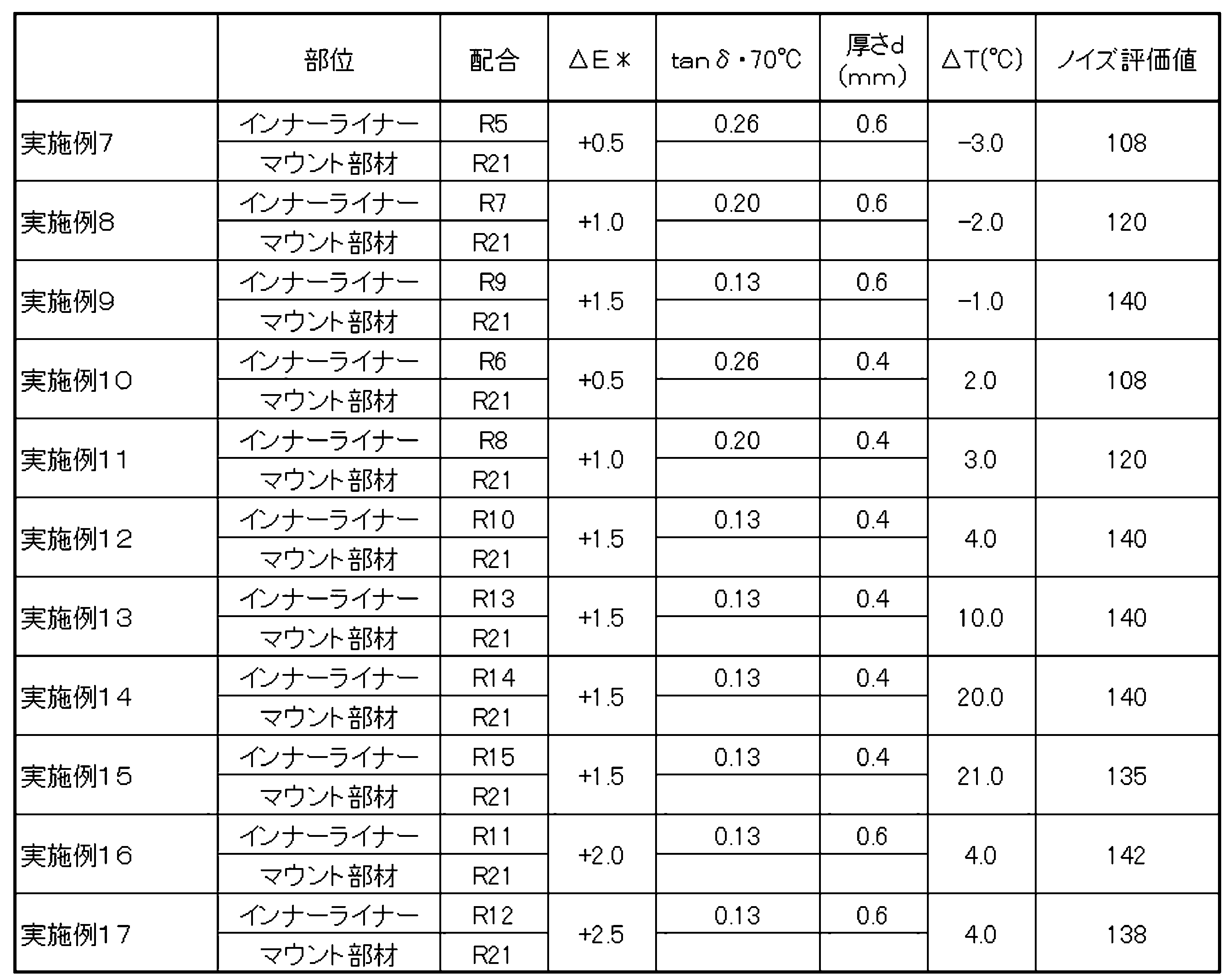
Claims (15)
- タイヤ表面を構成するトレッド部と、
タイヤ内面を構成するインナーライナーと、
前記タイヤ内面に設けられ、電気機器を装着可能なマウント部材と、を備え、
前記マウント部材を構成する第1ゴム組成物の70℃における複素弾性率E*1は測定温度70℃、初期歪み5%、動歪み±1%、周波数10Hz、及び伸長変形モードの測定条件の下で測定され、前記インナーライナーを構成する第2ゴム組成物の70℃における複素弾性率E*2は前記測定条件の下で測定され、
前記第1ゴム組成物の70℃における前記複素弾性率E*1は、前記第2ゴム組成物の70℃における前記複素弾性率E*2よりも大きいタイヤ。 - 前記第1ゴム組成物の70℃における前記複素弾性率E*1と、前記第2ゴム組成物の70℃における前記複素弾性率E*2との差は、0.25MPa未満である、請求項1に記載のタイヤ。
- 測定温度70℃、初期歪み10%、動歪み±2.5%、周波数10Hz、及び伸長変形モードの測定条件の下で測定される前記インナーライナーを構成する前記第2ゴム組成物の70℃における損失正接tanδは、0.26以下である、請求項1又は2に記載のタイヤ。
- 測定温度70℃、初期歪み10%、動歪み±2.5%、周波数10Hz、及び伸長変形モードの測定条件の下で測定される前記インナーライナーを構成する前記第2ゴム組成物の70℃における損失正接tanδは、0.13以下である、請求項1又は2に記載のタイヤ。
- 前記インナーライナーよりも前記トレッド部側に配置されたカーカス部を更に備え、
前記カーカス部における内部側の面から前記インナーライナーの内部側の面に至る厚さは0.6mm以上である、請求項1から4のいずれかに記載のタイヤ。 - 前記マウント部材の前記第1ゴム組成物のガラス転移温度T1は、周波数10Hz、初期歪10%、振幅±0.5%、及び昇温速度2℃/minの測定条件の下で測定される前記第1ゴム組成物の損失正接tanδの温度分布曲線におけるピーク位置に対応するピーク温度であり、
前記インナーライナーの前記第2ゴム組成物のガラス転移温度T2は、周波数10Hz、初期歪10%、振幅±0.5%、及び昇温速度2℃/minの測定条件の下で測定される前記第2ゴム組成物の損失正接tanδの温度分布曲線におけるピーク位置に対応するピーク温度であり、
前記ガラス転移温度T1は、前記ガラス転移温度T2よりも低い、請求項1から5のいずれかに記載のタイヤ。 - 前記ガラス転移温度T1と前記ガラス転移温度T2との差は、0℃よりも大きく20℃以下の範囲内である、請求項6に記載のタイヤ。
- 前記マウント部材は、前記タイヤ内面において前記トレッド部の幅方向中央部に対応する位置に配置されている、請求項1から7のいずれかに記載のタイヤ。
- 前記トレッド部は、前記タイヤ表面に形成された凹溝によって区分された陸部を有し、
前記マウント部材は、前記タイヤ内面において前記陸部に対応する位置に配置されている、請求項1から8のいずれかに記載のタイヤ。 - 前記マウント部材は、前記タイヤ内面に固定される取付座部と、前記電気機器を着脱可能に取り付ける本体部とを有する、請求項1から9のいずれかに記載のタイヤ。
- 前記マウント部材は、前記タイヤ内面に溶着されている、請求項1から10のいずれかに記載のタイヤ。
- 前記タイヤ内面に複数の前記マウント部材が設けられており、
前記複数のマウント部材は、前記タイヤ内面において、前記タイヤの周方向に沿って等間隔に配置されている、請求項1から11のいずれかに記載のタイヤ。 - 前記電気機器は、センサー、無線通信中継器、又は信号発信機である、請求項1から12のいずれかに記載のタイヤ。
- 前記タイヤが乗用車用タイヤである請求項1から13のいずれかに記載のタイヤ。
- 前記タイヤは、空気入りタイヤである請求項1から14のいずれかに記載のタイヤ。
Priority Applications (4)
| Application Number | Priority Date | Filing Date | Title |
|---|---|---|---|
| US18/277,707 US20240123771A1 (en) | 2021-02-25 | 2022-02-17 | Tire |
| CN202280012604.0A CN116917145A (zh) | 2021-02-25 | 2022-02-17 | 轮胎 |
| JP2023502333A JPWO2022181443A1 (ja) | 2021-02-25 | 2022-02-17 | |
| EP22759482.7A EP4275919A4 (en) | 2021-02-25 | 2022-02-17 | PNEUMATIC |
Applications Claiming Priority (2)
| Application Number | Priority Date | Filing Date | Title |
|---|---|---|---|
| JP2021-029073 | 2021-02-25 | ||
| JP2021029073 | 2021-02-25 |
Publications (1)
| Publication Number | Publication Date |
|---|---|
| WO2022181443A1 true WO2022181443A1 (ja) | 2022-09-01 |
Family
ID=83049358
Family Applications (1)
| Application Number | Title | Priority Date | Filing Date |
|---|---|---|---|
| PCT/JP2022/006415 WO2022181443A1 (ja) | 2021-02-25 | 2022-02-17 | タイヤ |
Country Status (5)
| Country | Link |
|---|---|
| US (1) | US20240123771A1 (ja) |
| EP (1) | EP4275919A4 (ja) |
| JP (1) | JPWO2022181443A1 (ja) |
| CN (1) | CN116917145A (ja) |
| WO (1) | WO2022181443A1 (ja) |
Citations (18)
| Publication number | Priority date | Publication date | Assignee | Title |
|---|---|---|---|---|
| US4414370A (en) | 1981-01-09 | 1983-11-08 | S. C. Johnson & Son, Inc. | Process for continuous bulk copolymerization of vinyl monomers |
| JPS596207A (ja) | 1982-06-15 | 1984-01-13 | エス・シ−・ジヨンソン・アンド・サン・インコ−ポレ−テツド | バルク重合方法とポリマ−生成物 |
| JPH01313522A (ja) | 1988-04-26 | 1989-12-19 | S C Johnson & Son Inc | 環状エステル修飾アクリル系ポリマーの触媒塊状製造方法 |
| US5010166A (en) | 1987-03-05 | 1991-04-23 | S. C. Johnson & Son, Inc. | Process and apparatus for producing polyol polymers and polyol polymers so produced |
| JPH0558005B2 (ja) | 1984-02-29 | 1993-08-25 | Johnson & Son Inc S C | |
| JP2000168320A (ja) * | 1998-12-04 | 2000-06-20 | Bridgestone Corp | タイヤ内面への監視装置の取付方法及び装置 |
| JP2002541003A (ja) * | 1999-11-24 | 2002-12-03 | ミシュラン ルシェルシェ エ テクニク ソシエテ アノニム | モニター付き自動車タイヤと、モニターの保持組立体 |
| DE10209580A1 (de) * | 2002-03-05 | 2003-09-25 | Dunlop Gmbh & Co Kg | Fahrzeugreifen mit integriertem Transponder |
| JP2004155352A (ja) | 2002-11-07 | 2004-06-03 | Denso Corp | タイヤ圧力監視システム及びタイヤ圧力監視システムにおけるidコードの登録方法 |
| JP2005178761A (ja) * | 2003-12-16 | 2005-07-07 | Soc D Technologie Michelin | タイヤ内部に装置を取り付けるためのポストパッチ |
| JP2006507495A (ja) * | 2002-11-26 | 2006-03-02 | アイキュウ・モビール・ゲーエムベーハー | 電子部品を固着するための保持装置 |
| JP2006306171A (ja) * | 2005-04-26 | 2006-11-09 | Bridgestone Corp | 保護部材、電子式モニター装置及び空気入りタイヤ |
| JP2007069775A (ja) * | 2005-09-07 | 2007-03-22 | Sumitomo Rubber Ind Ltd | ランフラットタイヤ |
| JP2009113794A (ja) * | 2007-10-18 | 2009-05-28 | Sumitomo Rubber Ind Ltd | タイヤ |
| WO2013005639A1 (ja) * | 2011-07-01 | 2013-01-10 | 株式会社ブリヂストン | 取付構造体 |
| US20140261944A1 (en) * | 2013-03-15 | 2014-09-18 | The Goodyear Tire & Rubber Company | Encasing for releasably containing a device and tire containing such encasing or encased device |
| JP2017088171A (ja) * | 2015-11-13 | 2017-05-25 | ハンコック タイヤ カンパニー リミテッド | センサーパッチを備えるタイヤセンサー設置構造及びこれの製造方法 |
| WO2019244349A1 (ja) * | 2018-06-22 | 2019-12-26 | 横浜ゴム株式会社 | 空気入りタイヤおよびアセンブリシート |
Family Cites Families (3)
| Publication number | Priority date | Publication date | Assignee | Title |
|---|---|---|---|---|
| JP2916082B2 (ja) * | 1993-08-10 | 1999-07-05 | 住友ゴム工業株式会社 | 空気入りラジアルタイヤ |
| US5500065A (en) * | 1994-06-03 | 1996-03-19 | Bridgestone/Firestone, Inc. | Method for embedding a monitoring device within a tire during manufacture |
| DE112013006231T5 (de) * | 2012-12-26 | 2015-10-01 | Toyo Tire & Rubber Co., Ltd. | Pneumatischer Reifen und Verfahren zur Herstellung desselben |
-
2022
- 2022-02-17 EP EP22759482.7A patent/EP4275919A4/en active Pending
- 2022-02-17 CN CN202280012604.0A patent/CN116917145A/zh active Pending
- 2022-02-17 JP JP2023502333A patent/JPWO2022181443A1/ja active Pending
- 2022-02-17 WO PCT/JP2022/006415 patent/WO2022181443A1/ja active Application Filing
- 2022-02-17 US US18/277,707 patent/US20240123771A1/en active Pending
Patent Citations (18)
| Publication number | Priority date | Publication date | Assignee | Title |
|---|---|---|---|---|
| US4414370A (en) | 1981-01-09 | 1983-11-08 | S. C. Johnson & Son, Inc. | Process for continuous bulk copolymerization of vinyl monomers |
| JPS596207A (ja) | 1982-06-15 | 1984-01-13 | エス・シ−・ジヨンソン・アンド・サン・インコ−ポレ−テツド | バルク重合方法とポリマ−生成物 |
| JPH0558005B2 (ja) | 1984-02-29 | 1993-08-25 | Johnson & Son Inc S C | |
| US5010166A (en) | 1987-03-05 | 1991-04-23 | S. C. Johnson & Son, Inc. | Process and apparatus for producing polyol polymers and polyol polymers so produced |
| JPH01313522A (ja) | 1988-04-26 | 1989-12-19 | S C Johnson & Son Inc | 環状エステル修飾アクリル系ポリマーの触媒塊状製造方法 |
| JP2000168320A (ja) * | 1998-12-04 | 2000-06-20 | Bridgestone Corp | タイヤ内面への監視装置の取付方法及び装置 |
| JP2002541003A (ja) * | 1999-11-24 | 2002-12-03 | ミシュラン ルシェルシェ エ テクニク ソシエテ アノニム | モニター付き自動車タイヤと、モニターの保持組立体 |
| DE10209580A1 (de) * | 2002-03-05 | 2003-09-25 | Dunlop Gmbh & Co Kg | Fahrzeugreifen mit integriertem Transponder |
| JP2004155352A (ja) | 2002-11-07 | 2004-06-03 | Denso Corp | タイヤ圧力監視システム及びタイヤ圧力監視システムにおけるidコードの登録方法 |
| JP2006507495A (ja) * | 2002-11-26 | 2006-03-02 | アイキュウ・モビール・ゲーエムベーハー | 電子部品を固着するための保持装置 |
| JP2005178761A (ja) * | 2003-12-16 | 2005-07-07 | Soc D Technologie Michelin | タイヤ内部に装置を取り付けるためのポストパッチ |
| JP2006306171A (ja) * | 2005-04-26 | 2006-11-09 | Bridgestone Corp | 保護部材、電子式モニター装置及び空気入りタイヤ |
| JP2007069775A (ja) * | 2005-09-07 | 2007-03-22 | Sumitomo Rubber Ind Ltd | ランフラットタイヤ |
| JP2009113794A (ja) * | 2007-10-18 | 2009-05-28 | Sumitomo Rubber Ind Ltd | タイヤ |
| WO2013005639A1 (ja) * | 2011-07-01 | 2013-01-10 | 株式会社ブリヂストン | 取付構造体 |
| US20140261944A1 (en) * | 2013-03-15 | 2014-09-18 | The Goodyear Tire & Rubber Company | Encasing for releasably containing a device and tire containing such encasing or encased device |
| JP2017088171A (ja) * | 2015-11-13 | 2017-05-25 | ハンコック タイヤ カンパニー リミテッド | センサーパッチを備えるタイヤセンサー設置構造及びこれの製造方法 |
| WO2019244349A1 (ja) * | 2018-06-22 | 2019-12-26 | 横浜ゴム株式会社 | 空気入りタイヤおよびアセンブリシート |
Non-Patent Citations (2)
| Title |
|---|
| See also references of EP4275919A4 |
| TOA GOSEI, RESEARCH ANNUAL REPORT TREND, vol. 2000, no. 3, pages 42 - 45 |
Also Published As
| Publication number | Publication date |
|---|---|
| EP4275919A1 (en) | 2023-11-15 |
| CN116917145A (zh) | 2023-10-20 |
| US20240123771A1 (en) | 2024-04-18 |
| EP4275919A4 (en) | 2024-06-26 |
| JPWO2022181443A1 (ja) | 2022-09-01 |
Similar Documents
| Publication | Publication Date | Title |
|---|---|---|
| WO2022123853A1 (ja) | タイヤ | |
| WO2022181443A1 (ja) | タイヤ | |
| JP7392356B2 (ja) | タイヤ | |
| EP4049856A1 (en) | Tire | |
| EP4245569A1 (en) | Tire | |
| JP7014274B1 (ja) | 重荷重用タイヤ | |
| AU2021273607A1 (en) | Tire | |
| WO2022181442A1 (ja) | タイヤ | |
| EP4130363A1 (en) | Tire cord and tire | |
| WO2022181267A1 (ja) | タイヤ | |
| WO2023171320A1 (ja) | タイヤ | |
| EP4269131A1 (en) | Tire | |
| JP7501180B2 (ja) | タイヤ | |
| JP2023060432A (ja) | 空気入りタイヤ | |
| JP6483771B1 (ja) | 空気入りタイヤ | |
| JP2023149903A (ja) | トレッド用ゴム組成物及びタイヤ | |
| JP2022139135A (ja) | タイヤ | |
| JP2022164066A (ja) | ベース部用ゴム組成物 | |
| JP2021172227A (ja) | タイヤ | |
| JP2024060451A (ja) | タイヤ | |
| JP2024115417A (ja) | タイヤ | |
| JP2024115419A (ja) | タイヤ | |
| JP2024066116A (ja) | タイヤ | |
| JP2024032595A (ja) | タイヤ | |
| JP2022106495A (ja) | 空気入りタイヤ |
Legal Events
| Date | Code | Title | Description |
|---|---|---|---|
| 121 | Ep: the epo has been informed by wipo that ep was designated in this application |
Ref document number: 22759482 Country of ref document: EP Kind code of ref document: A1 |
|
| ENP | Entry into the national phase |
Ref document number: 2023502333 Country of ref document: JP Kind code of ref document: A |
|
| WWE | Wipo information: entry into national phase |
Ref document number: 202280012604.0 Country of ref document: CN |
|
| ENP | Entry into the national phase |
Ref document number: 2022759482 Country of ref document: EP Effective date: 20230808 |
|
| WWE | Wipo information: entry into national phase |
Ref document number: 18277707 Country of ref document: US |
|
| NENP | Non-entry into the national phase |
Ref country code: DE |