WO2022180784A1 - 回転電機 - Google Patents
回転電機 Download PDFInfo
- Publication number
- WO2022180784A1 WO2022180784A1 PCT/JP2021/007339 JP2021007339W WO2022180784A1 WO 2022180784 A1 WO2022180784 A1 WO 2022180784A1 JP 2021007339 W JP2021007339 W JP 2021007339W WO 2022180784 A1 WO2022180784 A1 WO 2022180784A1
- Authority
- WO
- WIPO (PCT)
- Prior art keywords
- rotor
- core
- metal ring
- electric machine
- bar
- Prior art date
- Legal status (The legal status is an assumption and is not a legal conclusion. Google has not performed a legal analysis and makes no representation as to the accuracy of the status listed.)
- Ceased
Links
Images


Classifications
-
- H—ELECTRICITY
- H02—GENERATION; CONVERSION OR DISTRIBUTION OF ELECTRIC POWER
- H02K—DYNAMO-ELECTRIC MACHINES
- H02K17/00—Asynchronous induction motors; Asynchronous induction generators
- H02K17/02—Asynchronous induction motors
- H02K17/16—Asynchronous induction motors having rotors with internally short-circuited windings, e.g. cage rotors
-
- H—ELECTRICITY
- H02—GENERATION; CONVERSION OR DISTRIBUTION OF ELECTRIC POWER
- H02K—DYNAMO-ELECTRIC MACHINES
- H02K1/00—Details of the magnetic circuit
- H02K1/06—Details of the magnetic circuit characterised by the shape, form or construction
- H02K1/22—Rotating parts of the magnetic circuit
- H02K1/28—Means for mounting or fastening rotating magnetic parts on to, or to, the rotor structures
- H02K1/30—Means for mounting or fastening rotating magnetic parts on to, or to, the rotor structures using intermediate parts, e.g. spiders
-
- H—ELECTRICITY
- H02—GENERATION; CONVERSION OR DISTRIBUTION OF ELECTRIC POWER
- H02K—DYNAMO-ELECTRIC MACHINES
- H02K15/00—Processes or apparatus specially adapted for manufacturing, assembling, maintaining or repairing of dynamo-electric machines
- H02K15/02—Processes or apparatus specially adapted for manufacturing, assembling, maintaining or repairing of dynamo-electric machines of stator or rotor bodies
- H02K15/021—Magnetic cores
- H02K15/023—Cage rotors
Definitions
- the present invention relates to rotating electric machines.
- each rotor core 12 is provided with a plurality of rotor slots 13 arranged at predetermined intervals in the circumferential direction.
- a plurality of rotor bars 14 are fixed so as to be arranged in parallel with the shaft 17.
- Patent Document 2 a method of fixing the rotor bar and the end ring by brazing is known.
- an object of the present invention is to provide a rotating electrical machine capable of suppressing imbalance of the rotor and vibration of the entire rotating electrical machine.
- One aspect of the present invention for solving the above problems includes a rotating shaft, a rotor fixed to the outer circumference of the rotating shaft, and a stator arranged on the outer circumference of the rotor, the rotor being fixed by a core clamp.
- a rotor core composed of a plurality of laminated iron cores; a rotor slot provided in the rotor core; and a rotor bar arranged in the rotor slot.
- a rotating electric machine characterized in that it has a metal ring, the other part of which is fixed to a core clamp.
- FIG. 10 is a diagram showing a rotor bar, a metal ring, and a core clamp of the rotary electric machine of Embodiment 2; Schematic diagram showing the mechanism of deformation due to brazing of the rotor core clamp and fixing member
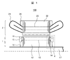
- FIG. 1 is an axial cross-sectional view of the rotating electrical machine of Example 1.
- FIG. FIG. 1 shows an example of an induction motor as a rotating electric machine.
- the rotary electric machine 100 includes a shaft (shaft) 17 serving as a rotation axis, a rotor 1 fixed to the outer circumference of the shaft 17 , and a stator 2 arranged to surround the outer circumference of the rotor 1 .
- a rotary electric machine (induction motor) 100 functions by rotating the rotor 1 around the shaft 17 as a rotation axis.
- a rotor core 12 that constitutes the rotor 1 is formed by laminating a plurality of electromagnetic steel sheets, and both ends thereof are clamped by annular rotor core clamps 18 to be integrated.
- the rotor core 12 is provided with a plurality of rotor slots (through holes) 13 arranged at predetermined intervals in the circumferential direction (circumferential direction) of the shaft 17 .
- a rotor bar 14 is press-fitted and fixed. Both ends of the rotor bar (also called squirrel cage conductor) 14 are connected to an annular metal ring 15 (also called “inner ring” or “short-circuit ring”) and an annular retaining ring 16 (also called “outer ring”). ) are brazed and fixed with silver or the like to form a squirrel cage rotor.
- the stator 2 has an annular stator core 22 fixed to the frame with a gap outside the rotor 1 .
- the stator core 22 is formed by laminating a plurality of electromagnetic steel sheets, and both ends thereof are clamped by annular stator core clamps 26 to be integrated.
- the stator core 22 has stator slots 23 in which a plurality of through holes are arranged at predetermined intervals in the circumferential direction. A stator winding 24 is inserted in this stator slot 23 .
- FIG. 2 is an enlarged view of the dashed line portion X in FIG.
- rotor core clamps 18 are positioned inside rotor slots 13 at opposite ends of rotor core 12 .
- the rotor core clamp 18 of this embodiment has an annular concave portion (thin-walled portion) 19 on the outer peripheral side.
- the side surface of the metal ring 15 is brazed to the rotor bar 14, and the metal ring 15 of this embodiment has an annular protrusion 20 that fits into the annular recess of the rotor core clamp 18. 19, and fixed so that there is substantially no gap between them. Furthermore, the rotor bar 14 and the metal ring 15 are fixed by the retaining ring 16 . By fixing the rotor core clamp 18 and the annular recess 19 of the metal ring 15 in this way, it is possible to reduce the unbalance of the rotor and suppress the vibration of the entire rotary electric machine without creating a gap between them.
- FIG. 4 is a schematic diagram showing a deformation mechanism due to brazing of the rotor bar and the metal ring.
- FIG. 4(a) shows the state of the rotor bar 14, metal ring 15 and core clamp 18 at room temperature before brazing.
- FIG. 4(b) is a diagram showing the state of the rotor bar 14 and the metal ring 15 at the time of brazing.
- the rotor bar 14 and the metal ring 15 are deformed by the heating and cooling process during the brazing of the rotor bar 14 and the metal ring 15. Since the portion 20 is fitted into the recessed portion of the rotor core clamp 18 to fill the gap between them, even if the rotor bar 14 and the metal ring 15 are deformed as shown in FIG. Deformation can be prevented by contact with 18 . As a result, it is possible to realize a rotating electrical machine capable of suppressing imbalance of the rotor and vibration of the entire rotating electrical machine.
- the metal ring 15 of this embodiment has a tapered surface (inner side) facing the rotor core 12 inside the rotor bar 14 and a tapered side (outer side) opposite to the surface facing the rotor core 12. have. By providing a taper in this manner, weight reduction can be achieved.
- FIG. 3 is a diagram showing the rotor bar, metal ring, and core clamp of the rotating electrical machine of Example 2.
- a different point from the configuration of the first embodiment is that the retaining ring 16 fixes only the metal ring 15 . Even with such a configuration, deformation of the rotor bar 14 and the metal ring 15 can be suppressed as in the first embodiment.
- the present invention is not limited to the above-described embodiments, and includes various modifications.
- the above-described embodiments have been described in detail in order to explain the present invention in an easy-to-understand manner, and are not necessarily limited to those having all the described configurations.
- part of the configuration of one embodiment can be replaced with the configuration of another embodiment, and the configuration of another embodiment can be added to the configuration of one embodiment.
Landscapes
- Engineering & Computer Science (AREA)
- Power Engineering (AREA)
- Manufacturing & Machinery (AREA)
- Induction Machinery (AREA)
- Iron Core Of Rotating Electric Machines (AREA)
Priority Applications (3)
| Application Number | Priority Date | Filing Date | Title |
|---|---|---|---|
| EP21856957.2A EP4300796A4 (en) | 2021-02-26 | 2021-02-26 | DYNAMO-ELECTRIC MACHINE |
| JP2021560031A JP7185073B1 (ja) | 2021-02-26 | 2021-02-26 | 回転電機 |
| PCT/JP2021/007339 WO2022180784A1 (ja) | 2021-02-26 | 2021-02-26 | 回転電機 |
Applications Claiming Priority (1)
| Application Number | Priority Date | Filing Date | Title |
|---|---|---|---|
| PCT/JP2021/007339 WO2022180784A1 (ja) | 2021-02-26 | 2021-02-26 | 回転電機 |
Publications (1)
| Publication Number | Publication Date |
|---|---|
| WO2022180784A1 true WO2022180784A1 (ja) | 2022-09-01 |
Family
ID=83048965
Family Applications (1)
| Application Number | Title | Priority Date | Filing Date |
|---|---|---|---|
| PCT/JP2021/007339 Ceased WO2022180784A1 (ja) | 2021-02-26 | 2021-02-26 | 回転電機 |
Country Status (3)
| Country | Link |
|---|---|
| EP (1) | EP4300796A4 (https=) |
| JP (1) | JP7185073B1 (https=) |
| WO (1) | WO2022180784A1 (https=) |
Citations (4)
| Publication number | Priority date | Publication date | Assignee | Title |
|---|---|---|---|---|
| JPH07131962A (ja) | 1993-11-02 | 1995-05-19 | Toshiba Corp | 回転子の製造方法 |
| JPH0946988A (ja) * | 1995-07-24 | 1997-02-14 | Toyo Electric Mfg Co Ltd | 車両用誘導電動機の回転子 |
| JP2018042333A (ja) | 2016-09-06 | 2018-03-15 | 株式会社日立製作所 | 回転電機およびそれを用いた駆動システム |
| WO2018055701A1 (ja) * | 2016-09-21 | 2018-03-29 | 三菱電機株式会社 | 誘導電動機の回転子及び誘導電動機 |
Family Cites Families (3)
| Publication number | Priority date | Publication date | Assignee | Title |
|---|---|---|---|---|
| JPS5721275U (https=) * | 1980-07-09 | 1982-02-03 | ||
| JPS5941161A (ja) * | 1982-08-31 | 1984-03-07 | Toshiba Corp | 誘導電動機のかご形回転子 |
| DE112017007176T5 (de) * | 2017-03-06 | 2019-12-24 | Mitsubishi Electric Corporation | Käfigläuferinduktionsmotor für ein Fahrzeug |
-
2021
- 2021-02-26 JP JP2021560031A patent/JP7185073B1/ja active Active
- 2021-02-26 EP EP21856957.2A patent/EP4300796A4/en active Pending
- 2021-02-26 WO PCT/JP2021/007339 patent/WO2022180784A1/ja not_active Ceased
Patent Citations (4)
| Publication number | Priority date | Publication date | Assignee | Title |
|---|---|---|---|---|
| JPH07131962A (ja) | 1993-11-02 | 1995-05-19 | Toshiba Corp | 回転子の製造方法 |
| JPH0946988A (ja) * | 1995-07-24 | 1997-02-14 | Toyo Electric Mfg Co Ltd | 車両用誘導電動機の回転子 |
| JP2018042333A (ja) | 2016-09-06 | 2018-03-15 | 株式会社日立製作所 | 回転電機およびそれを用いた駆動システム |
| WO2018055701A1 (ja) * | 2016-09-21 | 2018-03-29 | 三菱電機株式会社 | 誘導電動機の回転子及び誘導電動機 |
Also Published As
| Publication number | Publication date |
|---|---|
| EP4300796A4 (en) | 2024-11-27 |
| JPWO2022180784A1 (https=) | 2022-09-01 |
| EP4300796A1 (en) | 2024-01-03 |
| JP7185073B1 (ja) | 2022-12-06 |
Similar Documents
| Publication | Publication Date | Title |
|---|---|---|
| JP7082885B2 (ja) | 回転電機のステータ | |
| US7911108B2 (en) | Stator of electric rotating machine | |
| JP2013219904A (ja) | ステータの製造方法及びステータ | |
| KR102835931B1 (ko) | 유도 기계의 로터 및 로터의 케이지형 권선 조립 방법 | |
| JP7185073B1 (ja) | 回転電機 | |
| WO2021199376A1 (ja) | 固定子および回転電機 | |
| JP2016220404A (ja) | かご型誘導電動機およびかご型誘導電動機用回転子ならびに回転子製造方法 | |
| WO2020054029A1 (ja) | かご形回転子および回転電機 | |
| JP2015220950A (ja) | 回転電機 | |
| JPH08275470A (ja) | 永久磁石式回転電機の回転子およびその製造方法 | |
| WO2011114758A1 (ja) | ステータおよび回転電機 | |
| JP2023047885A (ja) | 回転電機 | |
| JP2010239680A (ja) | 回転電機用電機子及びその製造方法 | |
| JP7085501B2 (ja) | かご形誘導電動機およびかご形回転子 | |
| CN112042079B (zh) | 旋转电机 | |
| JP7209480B2 (ja) | 回転電機および回転電機の製造方法 | |
| JP3596688B2 (ja) | 整流子型回転電機の電機子 | |
| JP2023169954A (ja) | かご形回転子および誘導電動機 | |
| WO2020067350A1 (ja) | 回転電機のロータ | |
| JP2025110834A (ja) | 回転電機 | |
| JP6210160B2 (ja) | 同期リラクタンス回転電機 | |
| JP4863145B2 (ja) | 永久磁石形回転電機 | |
| JP2025037652A (ja) | かご形回転子及び誘導電動機 | |
| JP2017169373A (ja) | 回転子部材及び回転電機 | |
| JP6499033B2 (ja) | 回転電機 |
Legal Events
| Date | Code | Title | Description |
|---|---|---|---|
| ENP | Entry into the national phase |
Ref document number: 2021560031 Country of ref document: JP Kind code of ref document: A |
|
| 121 | Ep: the epo has been informed by wipo that ep was designated in this application |
Ref document number: 21856957 Country of ref document: EP Kind code of ref document: A1 |
|
| WWE | Wipo information: entry into national phase |
Ref document number: 2021856957 Country of ref document: EP |
|
| NENP | Non-entry into the national phase |
Ref country code: DE |
|
| ENP | Entry into the national phase |
Ref document number: 2021856957 Country of ref document: EP Effective date: 20230926 |