WO2022180784A1 - Dynamo-electric machine - Google Patents
Dynamo-electric machine Download PDFInfo
- Publication number
- WO2022180784A1 WO2022180784A1 PCT/JP2021/007339 JP2021007339W WO2022180784A1 WO 2022180784 A1 WO2022180784 A1 WO 2022180784A1 JP 2021007339 W JP2021007339 W JP 2021007339W WO 2022180784 A1 WO2022180784 A1 WO 2022180784A1
- Authority
- WO
- WIPO (PCT)
- Prior art keywords
- rotor
- core
- metal ring
- electric machine
- bar
- Prior art date
Links
- 239000002184 metal Substances 0.000 claims abstract description 31
- 229910052751 metal Inorganic materials 0.000 claims abstract description 31
- XEEYBQQBJWHFJM-UHFFFAOYSA-N Iron Chemical group [Fe] XEEYBQQBJWHFJM-UHFFFAOYSA-N 0.000 claims abstract description 3
- 238000005219 brazing Methods 0.000 description 9
- 238000010586 diagram Methods 0.000 description 5
- 238000000034 method Methods 0.000 description 3
- 241000555745 Sciuridae Species 0.000 description 2
- 229910000831 Steel Inorganic materials 0.000 description 2
- 239000004020 conductor Substances 0.000 description 2
- 230000008602 contraction Effects 0.000 description 2
- 238000001816 cooling Methods 0.000 description 2
- 238000010438 heat treatment Methods 0.000 description 2
- 230000006698 induction Effects 0.000 description 2
- 238000010030 laminating Methods 0.000 description 2
- 230000007246 mechanism Effects 0.000 description 2
- 239000010959 steel Substances 0.000 description 2
- 238000004804 winding Methods 0.000 description 2
- 230000000694 effects Effects 0.000 description 1
- 230000004048 modification Effects 0.000 description 1
- 238000012986 modification Methods 0.000 description 1
- 230000002093 peripheral effect Effects 0.000 description 1
- 230000008569 process Effects 0.000 description 1
- 229910052709 silver Inorganic materials 0.000 description 1
- 239000004332 silver Substances 0.000 description 1
- 239000013585 weight reducing agent Substances 0.000 description 1
Images


Classifications
-
- H—ELECTRICITY
- H02—GENERATION; CONVERSION OR DISTRIBUTION OF ELECTRIC POWER
- H02K—DYNAMO-ELECTRIC MACHINES
- H02K17/00—Asynchronous induction motors; Asynchronous induction generators
- H02K17/02—Asynchronous induction motors
- H02K17/16—Asynchronous induction motors having rotors with internally short-circuited windings, e.g. cage rotors
- H02K17/166—Asynchronous induction motors having rotors with internally short-circuited windings, e.g. cage rotors having short-circuited rotor windings
-
- H—ELECTRICITY
- H02—GENERATION; CONVERSION OR DISTRIBUTION OF ELECTRIC POWER
- H02K—DYNAMO-ELECTRIC MACHINES
- H02K1/00—Details of the magnetic circuit
- H02K1/06—Details of the magnetic circuit characterised by the shape, form or construction
- H02K1/22—Rotating parts of the magnetic circuit
- H02K1/28—Means for mounting or fastening rotating magnetic parts on to, or to, the rotor structures
- H02K1/30—Means for mounting or fastening rotating magnetic parts on to, or to, the rotor structures using intermediate parts, e.g. spiders
-
- H—ELECTRICITY
- H02—GENERATION; CONVERSION OR DISTRIBUTION OF ELECTRIC POWER
- H02K—DYNAMO-ELECTRIC MACHINES
- H02K15/00—Methods or apparatus specially adapted for manufacturing, assembling, maintaining or repairing of dynamo-electric machines
- H02K15/0012—Manufacturing cage rotors
Definitions
- the present invention relates to rotating electric machines.
- each rotor core 12 is provided with a plurality of rotor slots 13 arranged at predetermined intervals in the circumferential direction.
- a plurality of rotor bars 14 are fixed so as to be arranged in parallel with the shaft 17.
- Patent Document 2 a method of fixing the rotor bar and the end ring by brazing is known.
- an object of the present invention is to provide a rotating electrical machine capable of suppressing imbalance of the rotor and vibration of the entire rotating electrical machine.
- One aspect of the present invention for solving the above problems includes a rotating shaft, a rotor fixed to the outer circumference of the rotating shaft, and a stator arranged on the outer circumference of the rotor, the rotor being fixed by a core clamp.
- a rotor core composed of a plurality of laminated iron cores; a rotor slot provided in the rotor core; and a rotor bar arranged in the rotor slot.
- a rotating electric machine characterized in that it has a metal ring, the other part of which is fixed to a core clamp.
- FIG. 10 is a diagram showing a rotor bar, a metal ring, and a core clamp of the rotary electric machine of Embodiment 2; Schematic diagram showing the mechanism of deformation due to brazing of the rotor core clamp and fixing member
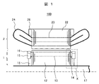
- FIG. 1 is an axial cross-sectional view of the rotating electrical machine of Example 1.
- FIG. FIG. 1 shows an example of an induction motor as a rotating electric machine.
- the rotary electric machine 100 includes a shaft (shaft) 17 serving as a rotation axis, a rotor 1 fixed to the outer circumference of the shaft 17 , and a stator 2 arranged to surround the outer circumference of the rotor 1 .
- a rotary electric machine (induction motor) 100 functions by rotating the rotor 1 around the shaft 17 as a rotation axis.
- a rotor core 12 that constitutes the rotor 1 is formed by laminating a plurality of electromagnetic steel sheets, and both ends thereof are clamped by annular rotor core clamps 18 to be integrated.
- the rotor core 12 is provided with a plurality of rotor slots (through holes) 13 arranged at predetermined intervals in the circumferential direction (circumferential direction) of the shaft 17 .
- a rotor bar 14 is press-fitted and fixed. Both ends of the rotor bar (also called squirrel cage conductor) 14 are connected to an annular metal ring 15 (also called “inner ring” or “short-circuit ring”) and an annular retaining ring 16 (also called “outer ring”). ) are brazed and fixed with silver or the like to form a squirrel cage rotor.
- the stator 2 has an annular stator core 22 fixed to the frame with a gap outside the rotor 1 .
- the stator core 22 is formed by laminating a plurality of electromagnetic steel sheets, and both ends thereof are clamped by annular stator core clamps 26 to be integrated.
- the stator core 22 has stator slots 23 in which a plurality of through holes are arranged at predetermined intervals in the circumferential direction. A stator winding 24 is inserted in this stator slot 23 .
- FIG. 2 is an enlarged view of the dashed line portion X in FIG.
- rotor core clamps 18 are positioned inside rotor slots 13 at opposite ends of rotor core 12 .
- the rotor core clamp 18 of this embodiment has an annular concave portion (thin-walled portion) 19 on the outer peripheral side.
- the side surface of the metal ring 15 is brazed to the rotor bar 14, and the metal ring 15 of this embodiment has an annular protrusion 20 that fits into the annular recess of the rotor core clamp 18. 19, and fixed so that there is substantially no gap between them. Furthermore, the rotor bar 14 and the metal ring 15 are fixed by the retaining ring 16 . By fixing the rotor core clamp 18 and the annular recess 19 of the metal ring 15 in this way, it is possible to reduce the unbalance of the rotor and suppress the vibration of the entire rotary electric machine without creating a gap between them.
- FIG. 4 is a schematic diagram showing a deformation mechanism due to brazing of the rotor bar and the metal ring.
- FIG. 4(a) shows the state of the rotor bar 14, metal ring 15 and core clamp 18 at room temperature before brazing.
- FIG. 4(b) is a diagram showing the state of the rotor bar 14 and the metal ring 15 at the time of brazing.
- the rotor bar 14 and the metal ring 15 are deformed by the heating and cooling process during the brazing of the rotor bar 14 and the metal ring 15. Since the portion 20 is fitted into the recessed portion of the rotor core clamp 18 to fill the gap between them, even if the rotor bar 14 and the metal ring 15 are deformed as shown in FIG. Deformation can be prevented by contact with 18 . As a result, it is possible to realize a rotating electrical machine capable of suppressing imbalance of the rotor and vibration of the entire rotating electrical machine.
- the metal ring 15 of this embodiment has a tapered surface (inner side) facing the rotor core 12 inside the rotor bar 14 and a tapered side (outer side) opposite to the surface facing the rotor core 12. have. By providing a taper in this manner, weight reduction can be achieved.
- FIG. 3 is a diagram showing the rotor bar, metal ring, and core clamp of the rotating electrical machine of Example 2.
- a different point from the configuration of the first embodiment is that the retaining ring 16 fixes only the metal ring 15 . Even with such a configuration, deformation of the rotor bar 14 and the metal ring 15 can be suppressed as in the first embodiment.
- the present invention is not limited to the above-described embodiments, and includes various modifications.
- the above-described embodiments have been described in detail in order to explain the present invention in an easy-to-understand manner, and are not necessarily limited to those having all the described configurations.
- part of the configuration of one embodiment can be replaced with the configuration of another embodiment, and the configuration of another embodiment can be added to the configuration of one embodiment.
Abstract
Description
Claims (5)
- 回転軸と、前記回転軸の外周に固定されたロータと、前記ロータの外周に配置されたステータと、を備え、
前記ロータは、コアクランプで固定された複数の積層鉄心で構成されるロータコアと、前記ロータコアに設けられたロータスロットと、前記ロータスロットに配置されたロータバーと、を有し、
前記ロータバーの端部に配置され、一部が前記ロータバーにろう付けされており、他の一部が前記コアクランプに固定されている金属環を有することを特徴とする回転電機。 A rotating shaft, a rotor fixed to the outer periphery of the rotating shaft, and a stator disposed on the outer periphery of the rotor,
The rotor has a rotor core composed of a plurality of laminated iron cores fixed with a core clamp, a rotor slot provided in the rotor core, and a rotor bar arranged in the rotor slot,
A rotating electric machine, comprising: a metal ring disposed at an end of the rotor bar, a part of which is brazed to the rotor bar, and another part of which is fixed to the core clamp. - 前記コアクランプは前記回転電機の外径側が環状であり、
前記金属環の前記他の一部が環状の突起部を有し、
前記環状の突起部が前記コアクランプの外側に対して隙間嵌めされていることを特徴とする請求項1に記載の回転電機。 The core clamp has an annular outer diameter side of the rotating electric machine,
the other part of the metal ring has an annular protrusion,
2. The electric rotating machine according to claim 1, wherein said annular protrusion is loosely fitted to the outside of said core clamp. - 前記コアクランプは薄肉部を有し、
前記金属環の前記環状の突起部と前記コアクランプの前記薄肉部とが隙間嵌めされていることを特徴とする請求項2に記載の回転電機。 The core clamp has a thin portion,
3. The electric rotating machine according to claim 2, wherein said annular protrusion of said metal ring and said thin portion of said core clamp are loosely fitted. - 前記金属環は、前記ロータバーより内側、かつ、前記ロータコアに対向する面にテーパを有することを特徴とする請求項1から3のいずれか1項に記載の回転電機。 The electric rotating machine according to any one of claims 1 to 3, wherein the metal ring has a tapered surface facing the rotor core inside the rotor bar.
- 前記金属環は、前記ロータコアに対向する面の反対面にテーパを有することを特徴とする請求項1から3のいずれか1項に記載の回転電機。 The rotating electric machine according to any one of claims 1 to 3, wherein the metal ring has a tapered surface opposite to the surface facing the rotor core.
Priority Applications (3)
| Application Number | Priority Date | Filing Date | Title |
|---|---|---|---|
| EP21856957.2A EP4300796A1 (en) | 2021-02-26 | 2021-02-26 | Dynamo-electric machine |
| PCT/JP2021/007339 WO2022180784A1 (en) | 2021-02-26 | 2021-02-26 | Dynamo-electric machine |
| JP2021560031A JP7185073B1 (en) | 2021-02-26 | 2021-02-26 | Rotating electric machine |
Applications Claiming Priority (1)
| Application Number | Priority Date | Filing Date | Title |
|---|---|---|---|
| PCT/JP2021/007339 WO2022180784A1 (en) | 2021-02-26 | 2021-02-26 | Dynamo-electric machine |
Publications (1)
| Publication Number | Publication Date |
|---|---|
| WO2022180784A1 true WO2022180784A1 (en) | 2022-09-01 |
Family
ID=83048965
Family Applications (1)
| Application Number | Title | Priority Date | Filing Date |
|---|---|---|---|
| PCT/JP2021/007339 WO2022180784A1 (en) | 2021-02-26 | 2021-02-26 | Dynamo-electric machine |
Country Status (3)
| Country | Link |
|---|---|
| EP (1) | EP4300796A1 (en) |
| JP (1) | JP7185073B1 (en) |
| WO (1) | WO2022180784A1 (en) |
Citations (4)
| Publication number | Priority date | Publication date | Assignee | Title |
|---|---|---|---|---|
| JPH07131962A (en) | 1993-11-02 | 1995-05-19 | Toshiba Corp | Manufacture of rotor |
| JPH0946988A (en) * | 1995-07-24 | 1997-02-14 | Toyo Electric Mfg Co Ltd | Rotor of induction motor for vehicle |
| JP2018042333A (en) | 2016-09-06 | 2018-03-15 | 株式会社日立製作所 | Rotary electric machine and drive system using the same |
| WO2018055701A1 (en) * | 2016-09-21 | 2018-03-29 | 三菱電機株式会社 | Rotor of induction motor and induction motor |
Family Cites Families (4)
| Publication number | Priority date | Publication date | Assignee | Title |
|---|---|---|---|---|
| JPS5721275U (en) * | 1980-07-09 | 1982-02-03 | ||
| JPS5941161A (en) * | 1982-08-31 | 1984-03-07 | Toshiba Corp | Squirrel-cage rotor for induction motor |
| WO2010121576A2 (en) | 2009-04-22 | 2010-10-28 | Institute Of Organic Chemistry And Biochemistry Ascr,V.V.I. | Novel 7-deazapurine nucleosides for therapeutic uses |
| WO2014103168A1 (en) | 2012-12-26 | 2014-07-03 | キヤノンアネルバ株式会社 | Substrate processing apparatus |
-
2021
- 2021-02-26 WO PCT/JP2021/007339 patent/WO2022180784A1/en active Application Filing
- 2021-02-26 EP EP21856957.2A patent/EP4300796A1/en active Pending
- 2021-02-26 JP JP2021560031A patent/JP7185073B1/en active Active
Patent Citations (4)
| Publication number | Priority date | Publication date | Assignee | Title |
|---|---|---|---|---|
| JPH07131962A (en) | 1993-11-02 | 1995-05-19 | Toshiba Corp | Manufacture of rotor |
| JPH0946988A (en) * | 1995-07-24 | 1997-02-14 | Toyo Electric Mfg Co Ltd | Rotor of induction motor for vehicle |
| JP2018042333A (en) | 2016-09-06 | 2018-03-15 | 株式会社日立製作所 | Rotary electric machine and drive system using the same |
| WO2018055701A1 (en) * | 2016-09-21 | 2018-03-29 | 三菱電機株式会社 | Rotor of induction motor and induction motor |
Also Published As
| Publication number | Publication date |
|---|---|
| JP7185073B1 (en) | 2022-12-06 |
| JPWO2022180784A1 (en) | 2022-09-01 |
| EP4300796A1 (en) | 2024-01-03 |
Similar Documents
| Publication | Publication Date | Title |
|---|---|---|
| US7911108B2 (en) | Stator of electric rotating machine | |
| JP7082885B2 (en) | Rotating machine stator | |
| WO2022180784A1 (en) | Dynamo-electric machine | |
| KR20200122250A (en) | A rotor of an induction machine and a method for assembling a cage winding of the rotor | |
| JP2013219904A (en) | Manufacturing method of stator and stator | |
| JP2016220404A (en) | Squirrel-cage induction motor, squirrel-cage induction motor rotor and rotor manufacturing method | |
| JP2020078099A (en) | Rotary electric machine | |
| JP2023047885A (en) | Rotary electric machine | |
| WO2021199376A1 (en) | Stator and dynamo-electric machine | |
| WO2020054029A1 (en) | Squirrel-cage rotor and rotating electric machine | |
| JPH08275470A (en) | Rotor of permanent-magnet type electric rotating machine and manufacture thereof | |
| JP7209480B2 (en) | Rotating electric machine and manufacturing method of rotating electric machine | |
| WO2020067350A1 (en) | Rotor of electric rotary machine | |
| JP2010239680A (en) | Armature for rotary electric machine and manufacturing method therefor | |
| JP5129518B2 (en) | Rotating electric machine | |
| WO2011114758A1 (en) | Stator and dynamo-electric machine | |
| JP2015220950A (en) | Rotating electrical machine | |
| JP2015216788A (en) | Fastening structure of stator split cores | |
| JP6210160B2 (en) | Synchronous reluctance rotating electric machine | |
| JP3596688B2 (en) | Armature of commutator type rotating electric machine | |
| JP2023169954A (en) | Squirrel-cage rotor and induction motor | |
| WO2023021839A1 (en) | Induction motor and railway vehicle | |
| JP2017169373A (en) | Rotor member and rotary electric machine | |
| JP4863145B2 (en) | Permanent magnet type rotating electric machine | |
| JP6499033B2 (en) | Rotating electric machine |
Legal Events
| Date | Code | Title | Description |
|---|---|---|---|
| ENP | Entry into the national phase |
Ref document number: 2021560031 Country of ref document: JP Kind code of ref document: A |
|
| 121 | Ep: the epo has been informed by wipo that ep was designated in this application |
Ref document number: 21856957 Country of ref document: EP Kind code of ref document: A1 |
|
| WWE | Wipo information: entry into national phase |
Ref document number: 2021856957 Country of ref document: EP |
|
| NENP | Non-entry into the national phase |
Ref country code: DE |
|
| ENP | Entry into the national phase |
Ref document number: 2021856957 Country of ref document: EP Effective date: 20230926 |