WO2022168236A1 - 鞍乗型車両、その制御方法、制御装置、及びプログラム - Google Patents
鞍乗型車両、その制御方法、制御装置、及びプログラム Download PDFInfo
- Publication number
- WO2022168236A1 WO2022168236A1 PCT/JP2021/004121 JP2021004121W WO2022168236A1 WO 2022168236 A1 WO2022168236 A1 WO 2022168236A1 JP 2021004121 W JP2021004121 W JP 2021004121W WO 2022168236 A1 WO2022168236 A1 WO 2022168236A1
- Authority
- WO
- WIPO (PCT)
- Prior art keywords
- vehicle
- straddle
- avoidance space
- type vehicle
- notification
- Prior art date
- Legal status (The legal status is an assumption and is not a legal conclusion. Google has not performed a legal analysis and makes no representation as to the accuracy of the status listed.)
- Ceased
Links
Images








Classifications
-
- B—PERFORMING OPERATIONS; TRANSPORTING
- B62—LAND VEHICLES FOR TRAVELLING OTHERWISE THAN ON RAILS
- B62J—CYCLE SADDLES OR SEATS; AUXILIARY DEVICES OR ACCESSORIES SPECIALLY ADAPTED TO CYCLES AND NOT OTHERWISE PROVIDED FOR, e.g. ARTICLE CARRIERS OR CYCLE PROTECTORS
- B62J27/00—Safety equipment
-
- B—PERFORMING OPERATIONS; TRANSPORTING
- B60—VEHICLES IN GENERAL
- B60K—ARRANGEMENT OR MOUNTING OF PROPULSION UNITS OR OF TRANSMISSIONS IN VEHICLES; ARRANGEMENT OR MOUNTING OF PLURAL DIVERSE PRIME-MOVERS IN VEHICLES; AUXILIARY DRIVES FOR VEHICLES; INSTRUMENTATION OR DASHBOARDS FOR VEHICLES; ARRANGEMENTS IN CONNECTION WITH COOLING, AIR INTAKE, GAS EXHAUST OR FUEL SUPPLY OF PROPULSION UNITS IN VEHICLES
- B60K35/00—Instruments specially adapted for vehicles; Arrangement of instruments in or on vehicles
- B60K35/20—Output arrangements, i.e. from vehicle to user, associated with vehicle functions or specially adapted therefor
- B60K35/21—Output arrangements, i.e. from vehicle to user, associated with vehicle functions or specially adapted therefor using visual output, e.g. blinking lights or matrix displays
- B60K35/22—Display screens
-
- B—PERFORMING OPERATIONS; TRANSPORTING
- B60—VEHICLES IN GENERAL
- B60K—ARRANGEMENT OR MOUNTING OF PROPULSION UNITS OR OF TRANSMISSIONS IN VEHICLES; ARRANGEMENT OR MOUNTING OF PLURAL DIVERSE PRIME-MOVERS IN VEHICLES; AUXILIARY DRIVES FOR VEHICLES; INSTRUMENTATION OR DASHBOARDS FOR VEHICLES; ARRANGEMENTS IN CONNECTION WITH COOLING, AIR INTAKE, GAS EXHAUST OR FUEL SUPPLY OF PROPULSION UNITS IN VEHICLES
- B60K35/00—Instruments specially adapted for vehicles; Arrangement of instruments in or on vehicles
- B60K35/20—Output arrangements, i.e. from vehicle to user, associated with vehicle functions or specially adapted therefor
- B60K35/28—Output arrangements, i.e. from vehicle to user, associated with vehicle functions or specially adapted therefor characterised by the type of the output information, e.g. video entertainment or vehicle dynamics information; characterised by the purpose of the output information, e.g. for attracting the attention of the driver
-
- B—PERFORMING OPERATIONS; TRANSPORTING
- B62—LAND VEHICLES FOR TRAVELLING OTHERWISE THAN ON RAILS
- B62J—CYCLE SADDLES OR SEATS; AUXILIARY DEVICES OR ACCESSORIES SPECIALLY ADAPTED TO CYCLES AND NOT OTHERWISE PROVIDED FOR, e.g. ARTICLE CARRIERS OR CYCLE PROTECTORS
- B62J45/00—Electrical equipment arrangements specially adapted for use as accessories on cycles, not otherwise provided for
- B62J45/20—Cycle computers as cycle accessories
-
- B—PERFORMING OPERATIONS; TRANSPORTING
- B62—LAND VEHICLES FOR TRAVELLING OTHERWISE THAN ON RAILS
- B62J—CYCLE SADDLES OR SEATS; AUXILIARY DEVICES OR ACCESSORIES SPECIALLY ADAPTED TO CYCLES AND NOT OTHERWISE PROVIDED FOR, e.g. ARTICLE CARRIERS OR CYCLE PROTECTORS
- B62J45/00—Electrical equipment arrangements specially adapted for use as accessories on cycles, not otherwise provided for
- B62J45/40—Sensor arrangements; Mounting thereof
- B62J45/41—Sensor arrangements; Mounting thereof characterised by the type of sensor
-
- B—PERFORMING OPERATIONS; TRANSPORTING
- B62—LAND VEHICLES FOR TRAVELLING OTHERWISE THAN ON RAILS
- B62J—CYCLE SADDLES OR SEATS; AUXILIARY DEVICES OR ACCESSORIES SPECIALLY ADAPTED TO CYCLES AND NOT OTHERWISE PROVIDED FOR, e.g. ARTICLE CARRIERS OR CYCLE PROTECTORS
- B62J50/00—Arrangements specially adapted for use on cycles not provided for in main groups B62J1/00 - B62J45/00
- B62J50/20—Information-providing devices
- B62J50/21—Information-providing devices intended to provide information to rider or passenger
- B62J50/22—Information-providing devices intended to provide information to rider or passenger electronic, e.g. displays
-
- B—PERFORMING OPERATIONS; TRANSPORTING
- B62—LAND VEHICLES FOR TRAVELLING OTHERWISE THAN ON RAILS
- B62K—CYCLES; CYCLE FRAMES; CYCLE STEERING DEVICES; RIDER-OPERATED TERMINAL CONTROLS SPECIALLY ADAPTED FOR CYCLES; CYCLE AXLE SUSPENSIONS; CYCLE SIDECARS, FORECARS, OR THE LIKE
- B62K21/00—Steering devices
-
- G—PHYSICS
- G08—SIGNALLING
- G08G—TRAFFIC CONTROL SYSTEMS
- G08G1/00—Traffic control systems for road vehicles
- G08G1/16—Anti-collision systems
-
- B—PERFORMING OPERATIONS; TRANSPORTING
- B60—VEHICLES IN GENERAL
- B60K—ARRANGEMENT OR MOUNTING OF PROPULSION UNITS OR OF TRANSMISSIONS IN VEHICLES; ARRANGEMENT OR MOUNTING OF PLURAL DIVERSE PRIME-MOVERS IN VEHICLES; AUXILIARY DRIVES FOR VEHICLES; INSTRUMENTATION OR DASHBOARDS FOR VEHICLES; ARRANGEMENTS IN CONNECTION WITH COOLING, AIR INTAKE, GAS EXHAUST OR FUEL SUPPLY OF PROPULSION UNITS IN VEHICLES
- B60K2360/00—Indexing scheme associated with groups B60K35/00 or B60K37/00 relating to details of instruments or dashboards
- B60K2360/16—Type of output information
- B60K2360/168—Target or limit values
-
- B—PERFORMING OPERATIONS; TRANSPORTING
- B60—VEHICLES IN GENERAL
- B60K—ARRANGEMENT OR MOUNTING OF PROPULSION UNITS OR OF TRANSMISSIONS IN VEHICLES; ARRANGEMENT OR MOUNTING OF PLURAL DIVERSE PRIME-MOVERS IN VEHICLES; AUXILIARY DRIVES FOR VEHICLES; INSTRUMENTATION OR DASHBOARDS FOR VEHICLES; ARRANGEMENTS IN CONNECTION WITH COOLING, AIR INTAKE, GAS EXHAUST OR FUEL SUPPLY OF PROPULSION UNITS IN VEHICLES
- B60K2360/00—Indexing scheme associated with groups B60K35/00 or B60K37/00 relating to details of instruments or dashboards
- B60K2360/16—Type of output information
- B60K2360/179—Distances to obstacles or vehicles
-
- B—PERFORMING OPERATIONS; TRANSPORTING
- B60—VEHICLES IN GENERAL
- B60K—ARRANGEMENT OR MOUNTING OF PROPULSION UNITS OR OF TRANSMISSIONS IN VEHICLES; ARRANGEMENT OR MOUNTING OF PLURAL DIVERSE PRIME-MOVERS IN VEHICLES; AUXILIARY DRIVES FOR VEHICLES; INSTRUMENTATION OR DASHBOARDS FOR VEHICLES; ARRANGEMENTS IN CONNECTION WITH COOLING, AIR INTAKE, GAS EXHAUST OR FUEL SUPPLY OF PROPULSION UNITS IN VEHICLES
- B60K2360/00—Indexing scheme associated with groups B60K35/00 or B60K37/00 relating to details of instruments or dashboards
- B60K2360/18—Information management
- B60K2360/186—Displaying information according to relevancy
- B60K2360/1868—Displaying information according to relevancy according to driving situations
-
- B—PERFORMING OPERATIONS; TRANSPORTING
- B60—VEHICLES IN GENERAL
- B60Y—INDEXING SCHEME RELATING TO ASPECTS CROSS-CUTTING VEHICLE TECHNOLOGY
- B60Y2300/00—Purposes or special features of road vehicle drive control systems
- B60Y2300/18—Propelling the vehicle
- B60Y2300/18008—Propelling the vehicle related to particular drive situations
- B60Y2300/18166—Overtaking, changing lanes
Definitions
- the present invention relates to a straddle-type vehicle, its control method, control device, and program.
- Patent Literature 1 discloses displaying an image regarding a lane change when it is determined that the host vehicle will catch up with the preceding vehicle.
- Braking and turning can be considered as a means of avoiding contact with objects in front.
- a straddle-type vehicle is narrower than a four-wheeled vehicle and can pass through a narrower space than a four-wheeled vehicle.
- the rider needs to quickly decide whether to avoid the object in front of the vehicle by braking or by turning. desirable.
- An object of the present invention is to provide a technique for notifying a rider of information for avoidance by turning.
- forward detection means for detecting an object in front of the own vehicle; a first determination means for determining whether or not there is an avoidance space for avoiding contact with the object by turning when the own vehicle has a possibility of contact with the object; notification means for notifying information about the avoidance space when the first determination means determines that the avoidance space exists;
- FIG. 1 is a right side view of a straddle-type vehicle according to an embodiment
- FIG. FIG. 2 is a front view of the straddle-type vehicle of FIG. 1; The figure which shows the structural example of a meter panel.
- FIG. 2 is a block diagram showing a hardware configuration example of the saddle type vehicle
- 4 is a flowchart related to notification processing for avoiding contact with an object in front, which is executed by the control device;
- FIG. 2 is a diagram illustrating the positional relationship between a straddle-type vehicle and an object in front thereof; The figure which shows the structural example of the notification area
- FIG. 2 is a diagram illustrating the positional relationship between a straddle-type vehicle and an object in front thereof; The figure which shows the example of a display of the notification area
- FIG. 2 is a diagram illustrating the positional relationship between a straddle-type vehicle and an object in front thereof; 4 is a flowchart relating to notification processing for avoiding contact with an object in front, which is executed by the control device;
- FIG. 2 is a block diagram showing a hardware configuration example of the saddle type vehicle; 4 is a flowchart relating to notification processing for avoiding contact with an object in front, which is executed by the control device;
- arrows X, Y, and Z indicate directions orthogonal to each other, the X direction being the front-rear direction of the saddle-ride type vehicle, the Y direction being the vehicle width direction (horizontal direction) of the saddle-ride type vehicle, and the Z direction being the vertical direction.
- the left and right sides of the straddle-type vehicle are the left and right sides when viewed in the forward direction.
- the front or rear in the longitudinal direction of the straddle-type vehicle may simply be referred to as the front or rear.
- the inner side or the outer side in the vehicle width direction (horizontal direction) of the straddle-type vehicle may be simply referred to as the inner side or the outer side.
- FIG. 1 is a right side view of a straddle-type vehicle 1 according to an embodiment of the present invention
- FIG. 2 is a front view of the straddle-type vehicle 1 of FIG.
- the straddle-type vehicle 1 is a tourer-type motorcycle suitable for long-distance travel, but the present invention is applicable to various straddle-type vehicles including other types of motorcycles. It can be applied to an electric vehicle using a motor as a drive source as well as a vehicle using a motor as a drive source.
- the straddle-type vehicle 1 may be referred to as the vehicle 1 hereinafter.
- the vehicle 1 has a power unit 2 between the front wheels FW and the rear wheels RW.
- the power unit 2 includes a horizontally opposed six-cylinder engine 21 and a transmission 22 .
- the driving force of the transmission 22 is transmitted to the rear wheels RW via a drive shaft (not shown) to rotate the rear wheels RW.
- the power unit 2 is supported by the body frame 3.
- the body frame 3 includes a pair of left and right main frames 31 extending in the X direction.
- a fuel tank 5 and an air cleaner box (not shown) are arranged above the main frame 31 .
- a meter panel 500 is provided in front of the fuel tank 5 and includes an electronic image display device for displaying various information to the rider.
- FIG. 3 is a diagram showing a configuration example of the meter panel 500.
- the meter panel 500 displays a speedometer 501, a tachometer 502, and indicators 503 and 504 that indicate the pointing direction of the direction indicator.
- the meter panel 500 may display a fuel remaining amount gauge, a water temperature gauge, or the like.
- the meter panel 500 may be entirely composed of a display section such as a liquid crystal display or an organic EL display, or may be a combination of analog gauges and a display section.
- the meter panel 500 includes a notification area 505 for notifying the rider of information regarding the forward avoidance space by processing described later.
- the notification area 505 is provided in the central portion of the meter panel 500 that is easily visible to the rider, specifically between the speedometer 501 and the tachometer 502 and below the indicators 503 and 504 .
- a front end of the main frame 31 is provided with a head pipe 32 that rotatably supports a steering shaft (not shown) that is rotated by the handle 8 .
- a pair of left and right pivot plates 33 are provided at the rear end of the main frame 31 .
- a lower end portion of the pivot plate 33 and a front end portion of the main frame 31 are connected by a pair of left and right lower arms (not shown), and the power unit 2 is supported by the main frame 31 and the lower arms.
- a pair of left and right seat rails (not shown) extending rearward are provided at the rear end of the main frame 31.
- the seat rails are a seat 4a on which a rider sits, a seat 4b on which a fellow passenger sits, and a rear trunk. 7b etc. are supported.
- the pivot plate 33 swingably supports the front end of a rear swing arm (not shown) extending in the front-rear direction.
- the rear swing arm is vertically swingable, and the rear end supports the rear wheel RW.
- An exhaust muffler 6 that muffles exhaust noise from the engine 21 extends in the X direction below the rear wheel RW.
- Left and right saddlebags 7a are provided on the upper side of the rear wheel RW.
- a front suspension mechanism 9 that supports the front wheels FW is configured at the front end of the main frame 31 .
- a front wheel FW is rotatably supported by a front fork 95 of the front suspension mechanism 9 .
- Steering of the steering wheel 8 rotates the steering shaft of the front suspension mechanism 9 to steer the front wheels FW.
- the vehicle 1 includes a brake device 19F that brakes the front wheels FW and a brake device 19F that brakes the rear wheels RW.
- the brake devices 19F and 19R are configured to be operable by the rider's operation of the brake lever 8a or the brake pedal 8b.
- the brake devices 19F, 19R are, for example, disc brakes. When not distinguishing between the brake devices 19F and 19R, they are collectively referred to as the brake device 19. As shown in FIG.
- a headlight unit 11 that emits light in front of the vehicle 1 is arranged in the front part of the vehicle 1 .
- the headlight unit 11 of the present embodiment is a twin-lens type headlight unit that includes a right light irradiation section 11R and a left light irradiation section 11L symmetrically.
- a single-lens type headlight unit, a three-lens type headlight unit, or a left-right asymmetric binocular type headlight unit can also be employed.
- the front part of the vehicle 1 is covered with a front cowl 12, and the front side part of the vehicle 1 is covered with a pair of left and right side cowls 14.
- a screen 13 is arranged above the front cowl 12 .
- the screen 13 is a windshield that reduces the wind pressure applied to the rider during running, and is made of, for example, a transparent resin member.
- a pair of left and right side mirror units 15 are arranged on the sides of the front cowl 12 .
- a side mirror (not shown) is supported by the side mirror unit 15 so that the rider can visually recognize the rear.
- An imaging unit 16A and a radar 16B are arranged behind the front cowl 12 as detection devices for detecting the situation in front of the vehicle 1.
- the radar 16B is, for example, a millimeter wave radar.
- the image pickup unit 16A includes an image pickup device such as a CCD image sensor or a CMOS image sensor and an optical system such as a lens, and picks up an image in front of the vehicle 1 .
- the imaging unit 16A is arranged behind the upper portion of the front cowl 12. As shown in FIG. An opening 12a is formed through the front cowl 12, and the imaging unit 16A captures an image in front of the vehicle 1 through the opening 12a. Note that the arrangement of the imaging unit 16A and the radar 16B is an example.
- the imaging unit 16A and the radar 16B may be arranged at other positions such as under the jaw of the headlight unit 11 or inside.
- the radar 16B is arranged behind the front cowl 12. Due to the existence of the front cowl 12, the presence of the detection unit 16 can be made inconspicuous when viewed from the front of the vehicle 1, and deterioration of the appearance of the vehicle 1 can be avoided. A portion of the front cowl 12 located in front of the radar 16B is made of a material such as resin that allows transmission of electromagnetic waves.
- the imaging unit 16A and the radar 16B are arranged in the center of the front cowl 12 in the Y direction when viewed from the front of the vehicle.
- By arranging the imaging unit 16A and the radar 16B at the center of the vehicle 1 in the Y direction it is possible to obtain a wider imaging range and a wider detection range on the left and right sides in front of the vehicle 1, so that the situation in front of the vehicle 1 can be seen more clearly. It can be detected without oversight.
- one imaging unit 16A and one radar 16B can uniformly monitor the front of the vehicle 1 on the left and right sides, in a configuration in which one imaging unit 16A and one radar 16B are provided instead of providing a plurality of each, It is particularly advantageous.
- an imaging unit 20A and a radar 20B are arranged as detection devices for detecting the situation behind the vehicle 1.
- the image pickup unit 20A and the radar 20B may have the same configuration as the image pickup unit 16A and the radar 16B, respectively.
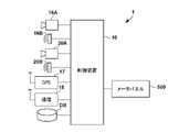
- FIG. 4 is a block diagram showing an example of the hardware configuration of the vehicle 1, and mainly shows the configuration required in relation to the description that will be given later.
- Vehicle 1 includes a control device 10 .
- the control device 10 includes, for example, an ECU.
- the control device 10 includes a processor represented by a CPU, a storage device such as a semiconductor memory, an input/output interface or a communication interface with an external device, and the like.
- the storage device stores programs executed by the processor, data used for processing by the processor, and the like.
- the control device 10 may include a plurality of sets of processors, storage devices, interfaces, etc. corresponding to each function of the vehicle 1 . Also, at least part of the functions of the control device 10 may be implemented by a known semiconductor device such as a PLD (Programmable Logic Device) or an ASIC (Application Specific Semiconductor Integrated Circuit).
- PLD Programmable Logic Device
- ASIC Application Specific Semiconductor Integrated Circuit
- the control device 10 acquires the detection results of the imaging unit 16A, the radar 16B, the imaging unit 20A, and the radar 20B, and constantly recognizes targets and road conditions around the vehicle 1. Also, the control device 10 acquires information from the GPS sensor 17, the communication device 18, and the map information database DB. A GPS sensor 17 detects the current position of the vehicle 1 .
- the communication device 18 wirelessly communicates with a server that provides map information and traffic information to acquire such information.
- the communication device 18 may also be used for vehicle-to-vehicle communication and road-to-vehicle communication, and can acquire information on other vehicles, for example. Highly accurate map information can be stored in the map information database DB, and the controller 10 can more accurately determine the shape of the road on which the vehicle is traveling and the position of the vehicle 1 on the lane based on this map information. Identifiable.
- the control device 10 can control the display of the meter panel 500.
- the control device 10 displays various notifications to the rider on the meter panel 500 .
- the control device 10 displays on the meter panel 500 a notification for the host vehicle to avoid contact with an object in front.
- the notification for contact avoidance is displayed as an image on the meter panel 500, but the notification may be displayed as an image on a head-up display or an in-vehicle display provided in the vehicle 1.
- the notification for contact avoidance may be lighting or blinking of a lamp, or notification by sound.
- the notification by voice may be controlled to output voice through wireless communication from a speaker provided on the rider's helmet. Further, the notification by the meter panel 500 or the like may be combined with these notifications.
- Avoidance actions include avoidance action by braking and avoidance action by turning. Depending on the positional relationship between the forward object and the vehicle 1, avoidance by turning may be more suitable.
- avoidance by turning it is necessary for the rider to quickly judge, for example, whether or not there is a space to avoid, but such information may be insufficient. be.
- FIG. 5 is a flowchart relating to notification processing for avoiding contact with an object in front, which is executed by the control device 10 .
- Each process described below is implemented in the control device 10 by the processor reading and executing a program stored in the storage device.
- the traffic rules for vehicles on the road are assumed to be left-hand traffic. Further, each process described below is periodically and repeatedly executed by the control device 10 .
- avoidance by turning includes avoidance of contact with an object in front, which involves movement in the width direction of the vehicle 1 .
- avoidance by turning includes movement to a space on the side of an object in front by steering the steering wheel 8 by the rider or tilting the body of the vehicle 1 by the rider.
- step S1 the control device 10 acquires sensor values of various sensors.
- the control device 10 acquires detection results of the imaging unit 16A and the radar 16B as sensor values of various sensors.
- the control device 10 may acquire information from the GPS sensor 17 or the communication device 18 .
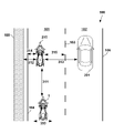
- FIG. 6 is a diagram illustrating the positional relationship between the vehicle 1 and objects in front of it.
- FIG. 6 shows a state in which the vehicle 1 is traveling in the left lane 101 on a two-lane road 100 .
- the preceding vehicle 200 is traveling in front of the vehicle 1 in the same traveling lane 101 as the vehicle 1, and the vehicle 201 is traveling in front of the vehicle 1 in the traveling lane 102 adjacent to the traveling lane 101.
- the control device 10 recognizes the presence of the preceding vehicle 200 and the vehicle 201 based on the sensor values acquired in S1. Further, for example, based on the sensor values acquired in S1, the control device 10 determines the speed difference and inter-vehicle distance 301 from the preceding vehicle 200, the left travelable width 302 of the preceding vehicle 200, or the right travelable width of the preceding vehicle 200. 303 etc. are recognized. In the example of FIG. 6 , the control device 10 recognizes the distance in the width direction from the preceding vehicle 200 to the area 105 such as a sidewalk bounded by guardrails, curbs, or the like as the possible travel width 302 .
- control device 10 may recognize the distance from the preceding vehicle 200 to the roadway outside line 104, which does not include the road shoulder portion of the road 100, as the travelable width. Further, the control device 10 recognizes the distance in the width direction from the preceding vehicle 200 to the vehicle 201 as the travelable width 303 . Note that the control device 10 may recognize the distance from the preceding vehicle 200 to the center line 106 as the travelable width.
- control device 10 may perform the surrounding situation recognition in S2 using the detection result of the imaging unit 16A, the detection result of the radar 16B, or both of these detections. You may execute using the result. Also, the control device 10 may perform the surrounding situation recognition in S2 based on other information. For example, the speed information of the preceding vehicle 200 and the inter-vehicle distance 301 may be acquired by vehicle-to-vehicle communication or road-to-vehicle communication by the communication device 18 .
- the control device 10 proceeds to S4 if there is a possibility that the vehicle will come into contact with an object in front, and ends the flowchart if there is no possibility of contact. For example, based on the inter-vehicle distance 301 and the speed difference between the vehicle 1 and the preceding vehicle 200, the control device 10 determines whether the vehicle 1 and the preceding vehicle 200 can contact each other within a predetermined period if the current state continues. to confirm. In the example of FIG. 6, when the speed of the vehicle 1 is greater than that of the preceding vehicle 200 and the current speed difference causes the vehicle 1 to contact the preceding vehicle 200 within a predetermined period of time, the control device 10 can contact the preceding vehicle. determine that it is viable. In the following description, FIG. 6 shows a state in which there is a possibility of contact between the vehicle 1 and the preceding vehicle 200. FIG.
- the recognition of the surrounding situation in S2 and the determination of the possibility of contact in S3 may be performed using the detection results of the same detection device, or may be performed using the detection results of different detection devices. For example, both determinations may be made using the detection results of the imaging unit 16A and the radar 16B, or the determination of S2 may be made using the detection results of the imaging unit 16A, and the determination of S3 may be made using the detection results of the radar 16B. may be used.
- the control device 10 determines whether or not there is an avoidance space for avoidance by turning. For example, the control device 10 may determine whether or not there is an avoidance space based on the surrounding conditions recognized in S ⁇ b>2 and information about the width direction of the vehicle 1 . Specifically, the control device 10 stores information on the necessary width 300 required for the vehicle 1 to pass in the storage device. When the travelable width 302 or the travelable width 303 is larger than the required width 300, it is determined that there is an avoidance space for avoidance by turning.
- the required width 300 may be a value obtained by adding a buffer to the width of the vehicle 1 itself.
- the required width 300 may be 1.1 to 3 times the width of the vehicle 1 itself.
- control device 10 proceeds to S6 if there is an avoidance space, and terminates the flowchart if there is no avoidance space.
- the process proceeds to S6.
- the control device 10 notifies information about the avoidance space.
- the control device 10 notifies the rider of the information about the avoidance space by displaying the information about the avoidance space in the notification area 505 of the meter panel 500 . After that, the flowchart ends.
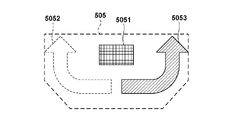
- FIG. 7 is a diagram showing a configuration example of the notification area 505 of the meter panel 500.
- the notification area 505 is configured to be able to display an object display image 5051 indicating that there is an object with a possibility of contact in front of the vehicle 1, and direction display images 5052 and 5053 indicating the direction in which there is an avoidance space for turning. .
- the preceding vehicle 200 which is an object that may come into contact with the vehicle 1, exists in front of the vehicle 1, and there is an avoidance space on the right side of the preceding vehicle 200. Therefore, in FIG. A direction display image 5053 indicating that there is an avoidance space is displayed.
- direction display image 5052 indicating that there is an avoidance space on the left side is not displayed (indicated by broken lines in the figure for convenience).
- the rider can visually recognize that there is an object in front that may collide with the object, but that the object can be avoided by turning to the right.
- the meter panel 500 may notify the information regarding the direction in which the vehicle 1 is likely to avoid contact with the preceding vehicle 200.
- the control device 10 may determine which direction, left or right, is the direction in which it is easier to avoid contact with the preceding vehicle 200 when there are avoidance spaces on both the left and right sides of the preceding vehicle 200 . Then, the control device 10 may display the direction display image 5052 or the direction display image 5053 corresponding to the easy avoidance direction in the notification area 505 .
- the direction in which contact with the preceding vehicle 200 can be easily avoided is determined, for example, by the size of the left and right travelable widths 322 and 323 of the preceding vehicle 200, the widthwise center of the vehicle 1 and the widthwise center of the preceding vehicle 200, and so on. deviation, other environmental parameters, and the like.
- FIG. 8 is a diagram illustrating the positional relationship between the vehicle 1 and objects in front of it.
- both the left travelable width 322 of the preceding vehicle 200 and the right travelable width 323 of the preceding vehicle 200 are larger than the required width 300 necessary for the vehicle 1 to pass. Therefore, in such a case, control device 10 determines which direction, left or right, is the direction in which it is easier to avoid contact with preceding vehicle 200 because avoidance spaces are present on both the left and right sides of preceding vehicle 200 .
- the control device 10 may determine that the right direction is the direction in which it is easier to avoid.
- the control device 10 may determine that the right direction is the direction in which it is easier to avoid. In this way, the control device 10 may determine the direction in which it is easy to avoid based on the position of the preceding vehicle 200, the relative positional relationship between the vehicle 1 and the preceding vehicle 200, and the like.
- the control device 10 determines that the direction in which these are not provided is the direction in which it is easier to avoid, and the notification area is displayed. A notification may be displayed at 505 .
- the control device 10 may determine that the left side of the preceding vehicle 200 rather than the right side of the preceding vehicle 200 in which the driving lane 102, which is an overtaking lane, is provided, is an easy direction to avoid.
- control device 10 may determine the direction in which it is easy to avoid based on environmental parameters such as road surface conditions and the width of the lane 101 in which the vehicle is currently traveling.
- the road surface conditions include, for example, the presence or absence of fallen leaves, ice, or wet portions.
- the control device 10 may acquire environmental parameters, for example, based on the detection results of the imaging unit 16A, or may receive information about the environmental parameters via the communication device 18 .
- both the direction display image 5052 and the direction display image 5053 are displayed and then , can also be adopted.
- the control device 10 may display a direction display image in a direction that is easy to avoid larger, or change the color of the direction display image in a direction that is easy to avoid.
- the information notified by the control device 10 includes information about the direction in which the vehicle 1 is likely to avoid contact with the preceding vehicle 200, so that the rider can grasp which direction, left or right, is easier to avoid. can be done.
- direction display image 5052 and direction display image 5053 on both the left and right sides are simply displayed when avoidance is possible on both left and right sides.
- FIG. 9 is a diagram showing a display example of the notification area 505 of the meter panel 500. As shown in FIG. Note that the display configurations exemplified below can be combined as appropriate.
- the width of the avoidance space is displayed as a numerical value as an example of notifying information about the width of the avoidance space.
- Exemplary display EX1 indicates that there is an avoidance space of 3.5 m to the right of the forward object. This allows the rider to recognize the width of the avoidance space as a specific numerical value.
- a display of 7.0 m or more may be made. A rider can intuitively recognize that the avoidance space is sufficient by the display such as "XX m or more".
- Display example EX2 shows another example of notifying information about the width of the avoidance space.
- Display example EX2 shows lane display images 5054 and 5055 indicating both ends of the travel lane 101 of the vehicle 1 and an object display image 5056 indicating the existence of the vehicle 201 traveling in the travel lane 102 adjacent to the travel lane 101 of the vehicle 1. ing.
- the width of the avoidance space is shown along with the vehicle interval display image 5057 between the object display images 5051 and 5052 .
- information regarding the width of the avoidance space may be displayed by changing the display mode of the direction display image 5053 or the vehicle interval display image 5057.
- the avoidance space is sufficiently secured (e.g. 7.0m or more), it is blue, if it is medium (e.g. 2.0m or more and less than 7.0m), it is yellow.
- the color of the direction display image 5053 or the vehicle interval display image 5057 may be changed, such as amber (orange) if the distance is less than 2.0 m.
- a display example EX3 shows an example in which information regarding whether or not it is possible to avoid contact with an object in the lane 101 on which the vehicle 1 is traveling is notified.
- Exemplary display EX3 indicates that there is an avoidance space on the right side of the forward object in which the vehicle can avoid contact with the forward object within the driving lane.
- the characters "IN" are displayed as information indicating that contact with an object can be avoided in the lane 101 on which the vehicle 1 is traveling.
- the direction display image 5053 is displayed so as to fit inside the lane display images 5054 and 5055 indicating both ends of the driving lane 101 of the vehicle 1 . Such a display allows the rider to recognize that the object in front can be avoided without changing lanes.
- Display example EX4 shows a display example when the vehicle 1 cannot avoid contact with an object in the traveling lane 101 in which it is traveling, that is, when the vehicle straddles an adjacent lane when avoiding contact. Specifically, the characters “OUT” are displayed in the notification area 505 , and the direction display image 5053 is displayed so as to straddle the lane display image 5055 .
- FIG. 10 is a diagram illustrating the positional relationship between the vehicle 1 and an object in front thereof.
- the preceding vehicle 210 is a straddle-type vehicle, and the space on the right side of the preceding vehicle 210 is particularly large.
- In-lane travelable width 315 which is the width of In the example of FIG. 10, since the required width 300 ⁇ the in-lane travelable width 315, the control device 10 displays an image like the display example EX3 in the notification area 505 in S6.
- information regarding the avoidance space is notified to the rider when there is a possibility of contact with an object in front. Therefore, information for avoidance by turning can be notified to the rider.
- the second embodiment differs from the first embodiment in that information regarding the avoidance space is notified at a timing at which the vehicle 1 can avoid contact with the preceding vehicle 200 .
- the same reference numerals are given to the same configurations as in the first embodiment, and the description thereof will be omitted.
- FIG. 11 is a flowchart relating to notification processing for avoiding contact with an object in front, which is executed by the control device 10 . Since S1 to S6 are the same as those in the flow chart of FIG. 5, description thereof will be omitted.
- control device 10 determines the notification timing in S21.
- the control device 10 proceeds to S6 to notify the meter panel 500 of the information regarding the avoidance space. to return to S22. Note that after waiting for a predetermined period of time, the process may return to S21 and determine the notification timing again.
- the notification timing may be determined, for example, based on whether the timing is such that the vehicle 1 can avoid contact with the preceding vehicle 200 .
- the control device 10 may control the notification timing so that the notification is displayed in the notification area 505 at the timing when the vehicle 1 can avoid contact with the preceding vehicle 200 .
- the control device 10 estimates the timing at which the vehicle 1 can avoid contact with the preceding vehicle 200, and adjusts the notification timing so that the notification is displayed in the notification area 505 a predetermined time before the estimated timing. may be controlled.
- the rider can recognize the information about the avoidance space at the timing when the rider can avoid it, and can immediately start the avoidance action by turning.
- Whether or not it is time to avoid contact with the preceding vehicle 200 may be determined, for example, based on information regarding the possibility of avoiding contact between the vehicle 1 and the preceding vehicle 200 . Specifically, whether or not it is possible to avoid the timing may be determined based on the relationship between the vehicle 1 and the preceding vehicle 200, the condition of the vehicle 1, environmental parameters, and parameters such as the rider's driving skill. good.
- Examples of the relationship between the vehicle 1 and the preceding vehicle 200 used to determine whether or not it is time to avoid contact with the preceding vehicle 200 include the inter-vehicle distance 301, or the speed between the vehicle 1 and the preceding vehicle 200. The difference, the amount of deviation of the center position in the width direction between the vehicle 1 and the preceding vehicle 200, and the like.
- the control device 10 determines that it is time to avoid contact with the preceding vehicle 200 by turning. good too. Further, the amount of movement of the vehicle 1 in the width direction differs depending on the shift in the center position in the width direction between the vehicle 1 and the preceding vehicle 200, so the time required to move to the avoidance space may change. Therefore, the control device 10 may determine whether or not it is avoidable timing based on the deviation of the widthwise center positions of the vehicle 1 and the preceding vehicle 200 .
- the conditions of the vehicle 1, which are used to determine whether or not it is time to avoid contact with the preceding vehicle 200, include whether the vehicle speed is capable of turning, and whether the acceleration and the inclination of the vehicle body are within the allowable range. is in, etc.
- Environmental parameters used to determine whether or not it is time to avoid contact with the preceding vehicle 200 include the road surface conditions, the width and inclination of the current lane 101, and whether or not the front is straight. and the status of The road surface conditions include, for example, the presence or absence of fallen leaves, ice, or wet portions.
- control device 10 may determine that it is not avoidable timing until the area is passed. However, even if there is a slippery area ahead, the control device 10 may determine that it is time to avoid the vehicle if the avoidance action by turning can be completed before reaching the area.
- the control device 10 may determine that the timing is not avoidable.
- control device 10 may acquire environmental parameters based on the detection result of the imaging unit 16A, for example, or may receive information about the environmental parameters through the communication device 18.
- the parameters of the rider's driving skill used to determine whether or not it is time to avoid contact with the preceding vehicle 200 include stability of the vehicle during straight running or turning, rapid acceleration, and rapid braking. frequency and the like.
- the vehicle 1 may be equipped with an IMU (Inertial Measurement Unit), the control device 10 may evaluate the rider's driving skill as described above based on the output data of the IMU during running, and store the evaluation result in a storage device. good. Then, for example, the control device 10 may control the notification timing so that the notification timing is earlier for a rider whose driving skill is low than for a rider whose driving skill is not low.
- IMU Inertial Measurement Unit
- control device 10 may determine whether or not it is time to avoid contact with the preceding vehicle 200 based on the behavior of the preceding vehicle 200 . For example, the control device 10 may acquire the position in the width direction, the moving speed, etc. of the preceding vehicle 200 based on the detection result of the detection unit 16 . Then, when the preceding vehicle 200 is moving in the width direction, the control device 10 estimates the avoidance space when passing the side of the preceding vehicle 200, and determines the avoidable timing based on the estimation result. You can judge. For example, if the preceding vehicle 200 is moving in a direction that reduces the avoidance space, the control device 10 may make a determination to postpone the avoidable timing.
- the preceding vehicle 200 is moving in the width direction and the vehicle 1 passes the side of the preceding vehicle 200. It is conceivable that a sufficient avoidance space is not ensured in this case.
- the control device 10 may suppress notification in such cases.
- the control device 10 may control notification timing based on the behavior of the vehicle behind. For example, when the avoidance space straddles the adjacent lane, when the distance between the vehicle 1 and the vehicle behind traveling in the adjacent lane is short, or when the speed of the vehicle behind is higher than the speed of the vehicle 1, the vehicle 1 It is conceivable that the vehicle will collide with the vehicle behind when entering the adjacent lane. Therefore, even if the contact with the preceding vehicle 200 can be avoided due to the relationship with the preceding vehicle 200, the control device 10 displays the notification area 505 when the distance or speed difference with the following vehicle is not within the allowable range. You may suppress the notification by . Note that the control device 10 may acquire the distance to the vehicle behind, the speed difference, etc., based on the detection result of the imaging unit 20A or the radar 20B.
- information regarding the avoidance space is notified to the rider at the timing at which the rider can execute a turning motion to avoid contact with the preceding vehicle 200 . Therefore, the rider can execute avoidance by turning at a more appropriate timing.
- the third embodiment differs from the first embodiment or the second embodiment in that driving assistance for turning motion is performed at a timing at which the vehicle can avoid contact with the preceding vehicle.
- driving assistance for turning motion is performed at a timing at which the vehicle can avoid contact with the preceding vehicle.
- FIG. 12 is a block diagram showing an example of the hardware configuration of the vehicle 900, and mainly shows the configuration necessary in relation to the explanation that will be described later.
- the vehicle 900 includes a turning assist device 901 that assists the turning motion of the rider.
- the turning support device 901 includes, for example, an actuator such as a motor for generating steering torque of the vehicle 1 .
- the control device 10 controls the steering torque generated by the turning support device 901 so that the steering shaft has a predetermined steering angle.
- control device 10 controls the operation of the power unit 2 and the brake 19 .
- the control device 10 recognizes the surrounding situation of the vehicle 900 based on the detection results of the detection unit 16 and the like, and controls the power unit 2, the brake 19, or the turning support device 901 based on the recognition results, thereby Driving support can be performed.
- FIG. 13 is a flowchart relating to notification processing for avoiding contact with an object in front, which is executed by the control device 10 . Since S1 to S6 are the same as those in the flow chart of FIG. 5, description thereof will be omitted.
- control device 10 notifies the meter panel 500 of information regarding the avoidance space in S6, and assists the turning operation with the turning support device 901 in S32. As a result, avoidance by turning to the avoidance space can be automatically performed.
- control device 10 may perform not only steering control by the turning support device 901 but also acceleration/deceleration control by the power unit 2 or the brake 19 .
- Notifications may be turned off.
- the control device 10 determines that the turning can not be avoided due to a change in the distance or speed difference from the preceding vehicle after determining that the turning can be avoided and notifying the avoidance space.
- the display in the notification area 505 may be stopped.
- the configuration of the notification area 505 is an example, and the display image may be changed or omitted as appropriate.
- the direction display images 5052 and 5053 may be symbols or characters other than arrows.
- the preceding vehicle 200 is used as an example of an object in front of the vehicle. It can be.
- control device 10 may suppresses notification of the avoidance space.
- control device 10 may cause meter panel 500 to display a notification prompting avoidance of contact with preceding vehicle 200 by braking.
- control device 10 may cause meter panel 500 to display that contact with preceding vehicle 200 can be avoided by braking or turning.
- the straddle-type vehicle (1) of the above embodiment is forward detection means (16A) for detecting an object in front of the own vehicle; a first judgment means (10, S4) for judging whether or not there is an avoidance space for avoiding contact with the object by turning when the own vehicle is likely to come into contact with the object; and notification means (500) for notifying information about the avoidance space when the first determination means determines that the avoidance space exists.
- information about the avoidance space is notified to the rider when there is a possibility of contact with an object ahead. Therefore, information for avoidance by turning can be notified to the rider.
- the information about the avoidance space includes information about the width of the avoidance space.
- information about the width of the avoidance space is notified to the rider, so the rider can recognize the ease of avoidance by turning.
- the information regarding the avoidance space includes information regarding whether or not it is possible for the vehicle to avoid contact with the object in the lane in which the vehicle is traveling.
- the rider can recognize whether or not contact with an object in front can be avoided without changing lanes.
- the information on the avoidance space includes information on the direction in which the object is easily avoided when the avoidance space exists on both left and right sides of the object.
- the rider can be urged to turn in a direction that is easier to avoid.
- a means is further provided (10, S21).
- the rider can recognize the avoidance space at avoidable timing.
- the object is a preceding vehicle;
- the second determination means determines the timing based on the behavior of the preceding vehicle in the width direction.
- the rider can recognize avoidable timing based on the behavior of the preceding vehicle.
- the second determination means determines the timing so as to suppress notification of information regarding the avoidance space based on the detection result of the rear detection means.
- the notification is suppressed according to the behavior of the vehicle behind, so it is possible to encourage the rider to avoid turning based on the behavior of the vehicle behind.
- the notification means provides notification by displaying information on the avoidance space on a meter (500) of the own vehicle.
- the rider can visually recognize information about the avoidance space.
- the control method of the above embodiment is a forward detection step (S1) of detecting an object in front of the own vehicle; a first determination step (S4) of determining whether or not there is an avoidance space for avoiding contact with the object by turning when the own vehicle has a possibility of contact with the object; and a notification step (S6) of notifying information about the avoidance space when it is determined in the first determination step that the avoidance space exists.
- information for avoidance by turning can be notified to the rider.
- the control device (10) of the above embodiment includes: A control device for a straddle-type vehicle (1) equipped with front detection means (16A) for detecting an object in front of the own vehicle, a first judgment means (S4) for judging whether or not there is an avoidance space for avoiding contact with the object by turning when the own vehicle is likely to come into contact with the object; a notification control means (S6) for notifying a notification means (500) of the straddle-type vehicle of information regarding the avoidance space when the first determination means determines that the avoidance space exists.
- information for avoidance by turning can be notified to the rider.
- the program of the above embodiment causes a computer to function as each means of the control device described in 12 above.
- information for avoidance by turning can be notified to the rider.
Landscapes
- Engineering & Computer Science (AREA)
- Mechanical Engineering (AREA)
- Chemical & Material Sciences (AREA)
- Combustion & Propulsion (AREA)
- Transportation (AREA)
- Physics & Mathematics (AREA)
- General Physics & Mathematics (AREA)
- Traffic Control Systems (AREA)
Priority Applications (5)
| Application Number | Priority Date | Filing Date | Title |
|---|---|---|---|
| CN202180092181.3A CN116802708A (zh) | 2021-02-04 | 2021-02-04 | 跨骑型车辆、跨骑型车辆的控制方法、控制装置及程序 |
| JP2022579242A JP7556986B2 (ja) | 2021-02-04 | 2021-02-04 | 鞍乗型車両、その制御方法、制御装置、及びプログラム |
| PCT/JP2021/004121 WO2022168236A1 (ja) | 2021-02-04 | 2021-02-04 | 鞍乗型車両、その制御方法、制御装置、及びプログラム |
| DE112021006993.4T DE112021006993T5 (de) | 2021-02-04 | 2021-02-04 | Fahrzeug vom spreitzsitztyp, verfahren zum steuern davon, steuerungsvorrichtung und programm |
| US18/226,878 US12545348B2 (en) | 2021-02-04 | 2023-07-27 | Straddle type vehicle, method for controlling the same, control apparatus, and storage medium |
Applications Claiming Priority (1)
| Application Number | Priority Date | Filing Date | Title |
|---|---|---|---|
| PCT/JP2021/004121 WO2022168236A1 (ja) | 2021-02-04 | 2021-02-04 | 鞍乗型車両、その制御方法、制御装置、及びプログラム |
Related Child Applications (1)
| Application Number | Title | Priority Date | Filing Date |
|---|---|---|---|
| US18/226,878 Continuation US12545348B2 (en) | 2021-02-04 | 2023-07-27 | Straddle type vehicle, method for controlling the same, control apparatus, and storage medium |
Publications (1)
| Publication Number | Publication Date |
|---|---|
| WO2022168236A1 true WO2022168236A1 (ja) | 2022-08-11 |
Family
ID=82741130
Family Applications (1)
| Application Number | Title | Priority Date | Filing Date |
|---|---|---|---|
| PCT/JP2021/004121 Ceased WO2022168236A1 (ja) | 2021-02-04 | 2021-02-04 | 鞍乗型車両、その制御方法、制御装置、及びプログラム |
Country Status (5)
| Country | Link |
|---|---|
| US (1) | US12545348B2 (https=) |
| JP (1) | JP7556986B2 (https=) |
| CN (1) | CN116802708A (https=) |
| DE (1) | DE112021006993T5 (https=) |
| WO (1) | WO2022168236A1 (https=) |
Cited By (2)
| Publication number | Priority date | Publication date | Assignee | Title |
|---|---|---|---|---|
| JP2023175515A (ja) * | 2022-05-30 | 2023-12-12 | ロベルト・ボッシュ・ゲゼルシャフト・ミト・ベシュレンクテル・ハフツング | 制御装置及び制御方法 |
| US12545348B2 (en) | 2021-02-04 | 2026-02-10 | Honda Motor Co., Ltd. | Straddle type vehicle, method for controlling the same, control apparatus, and storage medium |
Families Citing this family (1)
| Publication number | Priority date | Publication date | Assignee | Title |
|---|---|---|---|---|
| USD1031524S1 (en) * | 2024-03-20 | 2024-06-18 | Jianjun Chen | Electric motorcycle for kids |
Citations (2)
| Publication number | Priority date | Publication date | Assignee | Title |
|---|---|---|---|---|
| JP2018167732A (ja) * | 2017-03-30 | 2018-11-01 | 株式会社Subaru | 車両の走行制御装置 |
| US20190276013A1 (en) * | 2018-03-08 | 2019-09-12 | Mando Corporation | Apparatus and method for controlling collision avoidance of vehicle |
Family Cites Families (20)
| Publication number | Priority date | Publication date | Assignee | Title |
|---|---|---|---|---|
| JP4929970B2 (ja) | 2006-10-18 | 2012-05-09 | アイシン・エィ・ダブリュ株式会社 | 運転支援方法、運転支援装置及び運転支援システム |
| JP4730406B2 (ja) | 2008-07-11 | 2011-07-20 | トヨタ自動車株式会社 | 走行支援制御装置 |
| DE102009020649A1 (de) * | 2009-05-08 | 2010-11-18 | Daimler Ag | Verfahren und Vorrichtung zur Kollisionsvermeidung für ein Fahrzeug durch Ausweichen vor einem Hindernis |
| JP5199205B2 (ja) | 2009-09-04 | 2013-05-15 | 本田技研工業株式会社 | 車両制御装置 |
| US20140276014A1 (en) | 2013-03-13 | 2014-09-18 | Cephalogics, LLC | Supports for optical sensors and related apparatus and methods |
| JP6056682B2 (ja) | 2013-06-27 | 2017-01-11 | 株式会社デンソー | 車両用情報提供装置 |
| JP6354440B2 (ja) * | 2014-08-11 | 2018-07-11 | 日産自動車株式会社 | 走行制御装置および走行制御方法 |
| EP3335954A4 (en) * | 2015-08-17 | 2018-09-12 | Yamaha Hatsudoki Kabushiki Kaisha | Leaning vehicle |
| JP6423822B2 (ja) | 2016-06-23 | 2018-11-14 | 本田技研工業株式会社 | 車両制御装置 |
| JP7159600B2 (ja) | 2017-10-24 | 2022-10-25 | 株式会社デンソー | 車両制御装置、インタフェース装置、およびコンピュータ |
| JP7000851B2 (ja) * | 2017-12-28 | 2022-01-19 | スズキ株式会社 | 運転支援装置 |
| JP7113383B2 (ja) * | 2018-03-26 | 2022-08-05 | パナソニックIpマネジメント株式会社 | 運転支援システム、運転支援装置、運転支援方法 |
| KR20210000994A (ko) * | 2019-06-26 | 2021-01-06 | 현대자동차주식회사 | 차량 및 그 제어방법 |
| DE112020006505T5 (de) * | 2020-01-10 | 2022-12-01 | Denso Corporation | Präsentationssteuervorrichtung, präsentationssteuerprogramm und fahrsteuervorrichtung |
| JP7170682B2 (ja) | 2020-03-10 | 2022-11-14 | 本田技研工業株式会社 | 鞍乗型車両及び制御装置 |
| JP2021152780A (ja) | 2020-03-24 | 2021-09-30 | 本田技研工業株式会社 | 鞍乗型車両及び制御装置 |
| JP7394018B2 (ja) | 2020-05-21 | 2023-12-07 | 日立Astemo株式会社 | 車両制御装置 |
| CN116802708A (zh) | 2021-02-04 | 2023-09-22 | 本田技研工业株式会社 | 跨骑型车辆、跨骑型车辆的控制方法、控制装置及程序 |
| DE112021007005T5 (de) | 2021-02-04 | 2023-11-30 | Honda Motor Co., Ltd. | Grätschsitzfahrzeug, informationsverarbeitungsvorrichtung und informationsverarbeitungsverfahren |
| US11697466B1 (en) | 2021-09-23 | 2023-07-11 | Stephen Shelton | Motorcycle integrated safety system |
-
2021
- 2021-02-04 CN CN202180092181.3A patent/CN116802708A/zh active Pending
- 2021-02-04 WO PCT/JP2021/004121 patent/WO2022168236A1/ja not_active Ceased
- 2021-02-04 JP JP2022579242A patent/JP7556986B2/ja active Active
- 2021-02-04 DE DE112021006993.4T patent/DE112021006993T5/de active Pending
-
2023
- 2023-07-27 US US18/226,878 patent/US12545348B2/en active Active
Patent Citations (2)
| Publication number | Priority date | Publication date | Assignee | Title |
|---|---|---|---|---|
| JP2018167732A (ja) * | 2017-03-30 | 2018-11-01 | 株式会社Subaru | 車両の走行制御装置 |
| US20190276013A1 (en) * | 2018-03-08 | 2019-09-12 | Mando Corporation | Apparatus and method for controlling collision avoidance of vehicle |
Cited By (2)
| Publication number | Priority date | Publication date | Assignee | Title |
|---|---|---|---|---|
| US12545348B2 (en) | 2021-02-04 | 2026-02-10 | Honda Motor Co., Ltd. | Straddle type vehicle, method for controlling the same, control apparatus, and storage medium |
| JP2023175515A (ja) * | 2022-05-30 | 2023-12-12 | ロベルト・ボッシュ・ゲゼルシャフト・ミト・ベシュレンクテル・ハフツング | 制御装置及び制御方法 |
Also Published As
| Publication number | Publication date |
|---|---|
| JPWO2022168236A1 (https=) | 2022-08-11 |
| CN116802708A (zh) | 2023-09-22 |
| US20230365212A1 (en) | 2023-11-16 |
| DE112021006993T5 (de) | 2023-11-30 |
| US12545348B2 (en) | 2026-02-10 |
| JP7556986B2 (ja) | 2024-09-27 |
Similar Documents
| Publication | Publication Date | Title |
|---|---|---|
| JP6516089B2 (ja) | 車両情報投影システム及び車両情報投影方法 | |
| CN100405418C (zh) | 行驶控制装置及方法 | |
| CN101772791B (zh) | 驾驶辅助装置 | |
| US12545348B2 (en) | Straddle type vehicle, method for controlling the same, control apparatus, and storage medium | |
| US20120203435A1 (en) | Brake assist system | |
| JP2019084984A (ja) | 車両における制動支援装置および制動支援制御方法 | |
| WO2021060357A1 (ja) | Fcw制御装置を備えたリーン車両 | |
| JP7502479B2 (ja) | 鞍乗り型車両、情報処理装置、情報処理方法 | |
| CN113443051B (zh) | 跨骑型车辆以及控制装置 | |
| JP2022122534A (ja) | 車両、車両の制御方法、及びコンピュータプログラム | |
| JP2009166764A (ja) | 車両の接触回避支援装置 | |
| US20210300497A1 (en) | Saddle ride type vehicle and control apparatus | |
| JP2023045138A (ja) | 車両用表示装置、車両、表示方法及びプログラム | |
| JP7145179B2 (ja) | 鞍乗型車両及び制御装置 | |
| JP2022131239A (ja) | 車両、車両の制御方法、及びコンピュータプログラム | |
| JP7329055B2 (ja) | 車両の制御装置、車載装置及びプログラム | |
| JP7549529B2 (ja) | 制御装置、制御方法及び車両 | |
| JP6285291B2 (ja) | 操舵支援制御装置 | |
| WO2022201698A1 (ja) | 制御装置、警告制御方法およびプログラム | |
| JP2018073113A (ja) | 運転支援装置 | |
| JP5016502B2 (ja) | 車両の接触回避支援装置 | |
| JP7642789B2 (ja) | 車載装置、車両、情報処理方法、およびプログラム | |
| JP2025078498A (ja) | 運転支援装置および運転支援方法 | |
| JP2018073112A (ja) | 運転支援装置 | |
| JP2019121071A (ja) | 運転支援装置 |
Legal Events
| Date | Code | Title | Description |
|---|---|---|---|
| 121 | Ep: the epo has been informed by wipo that ep was designated in this application |
Ref document number: 21923610 Country of ref document: EP Kind code of ref document: A1 |
|
| WWE | Wipo information: entry into national phase |
Ref document number: 202180092181.3 Country of ref document: CN |
|
| WWE | Wipo information: entry into national phase |
Ref document number: 202317051747 Country of ref document: IN |
|
| WWE | Wipo information: entry into national phase |
Ref document number: 2022579242 Country of ref document: JP |
|
| WWE | Wipo information: entry into national phase |
Ref document number: 112021006993 Country of ref document: DE |
|
| 122 | Ep: pct application non-entry in european phase |
Ref document number: 21923610 Country of ref document: EP Kind code of ref document: A1 |