WO2022158092A1 - タイヤ搬送装置 - Google Patents
タイヤ搬送装置 Download PDFInfo
- Publication number
- WO2022158092A1 WO2022158092A1 PCT/JP2021/041586 JP2021041586W WO2022158092A1 WO 2022158092 A1 WO2022158092 A1 WO 2022158092A1 JP 2021041586 W JP2021041586 W JP 2021041586W WO 2022158092 A1 WO2022158092 A1 WO 2022158092A1
- Authority
- WO
- WIPO (PCT)
- Prior art keywords
- tire
- arms
- laser distance
- arm
- sensors
- Prior art date
- Legal status (The legal status is an assumption and is not a legal conclusion. Google has not performed a legal analysis and makes no representation as to the accuracy of the status listed.)
- Ceased
Links
Images






Classifications
-
- B—PERFORMING OPERATIONS; TRANSPORTING
- B65—CONVEYING; PACKING; STORING; HANDLING THIN OR FILAMENTARY MATERIAL
- B65G—TRANSPORT OR STORAGE DEVICES, e.g. CONVEYORS FOR LOADING OR TIPPING, SHOP CONVEYOR SYSTEMS OR PNEUMATIC TUBE CONVEYORS
- B65G47/00—Article or material-handling devices associated with conveyors; Methods employing such devices
- B65G47/74—Feeding, transfer, or discharging devices of particular kinds or types
- B65G47/90—Devices for picking-up and depositing articles or materials
-
- B—PERFORMING OPERATIONS; TRANSPORTING
- B66—HOISTING; LIFTING; HAULING
- B66C—CRANES; LOAD-ENGAGING ELEMENTS OR DEVICES FOR CRANES, CAPSTANS, WINCHES, OR TACKLES
- B66C1/00—Load-engaging elements or devices attached to lifting or lowering gear of cranes or adapted for connection therewith for transmitting lifting forces to articles or groups of articles
- B66C1/10—Load-engaging elements or devices attached to lifting or lowering gear of cranes or adapted for connection therewith for transmitting lifting forces to articles or groups of articles by mechanical means
- B66C1/62—Load-engaging elements or devices attached to lifting or lowering gear of cranes or adapted for connection therewith for transmitting lifting forces to articles or groups of articles by mechanical means comprising article-engaging members of a shape complementary to that of the articles to be handled
- B66C1/66—Load-engaging elements or devices attached to lifting or lowering gear of cranes or adapted for connection therewith for transmitting lifting forces to articles or groups of articles by mechanical means comprising article-engaging members of a shape complementary to that of the articles to be handled for engaging holes, recesses, or abutments on articles specially provided for facilitating handling thereof
-
- B—PERFORMING OPERATIONS; TRANSPORTING
- B29—WORKING OF PLASTICS; WORKING OF SUBSTANCES IN A PLASTIC STATE IN GENERAL
- B29D—PRODUCING PARTICULAR ARTICLES FROM PLASTICS OR FROM SUBSTANCES IN A PLASTIC STATE
- B29D30/00—Producing pneumatic or solid tyres or parts thereof
-
- B—PERFORMING OPERATIONS; TRANSPORTING
- B65—CONVEYING; PACKING; STORING; HANDLING THIN OR FILAMENTARY MATERIAL
- B65G—TRANSPORT OR STORAGE DEVICES, e.g. CONVEYORS FOR LOADING OR TIPPING, SHOP CONVEYOR SYSTEMS OR PNEUMATIC TUBE CONVEYORS
- B65G47/00—Article or material-handling devices associated with conveyors; Methods employing such devices
- B65G47/74—Feeding, transfer, or discharging devices of particular kinds or types
- B65G47/90—Devices for picking-up and depositing articles or materials
- B65G47/905—Control arrangements
-
- B—PERFORMING OPERATIONS; TRANSPORTING
- B66—HOISTING; LIFTING; HAULING
- B66C—CRANES; LOAD-ENGAGING ELEMENTS OR DEVICES FOR CRANES, CAPSTANS, WINCHES, OR TACKLES
- B66C1/00—Load-engaging elements or devices attached to lifting or lowering gear of cranes or adapted for connection therewith for transmitting lifting forces to articles or groups of articles
- B66C1/10—Load-engaging elements or devices attached to lifting or lowering gear of cranes or adapted for connection therewith for transmitting lifting forces to articles or groups of articles by mechanical means
- B66C1/22—Rigid members, e.g. L-shaped members, with parts engaging the under surface of the loads; Crane hooks
- B66C1/28—Duplicate, e.g. pivoted, members engaging the loads from two sides
-
- B—PERFORMING OPERATIONS; TRANSPORTING
- B66—HOISTING; LIFTING; HAULING
- B66C—CRANES; LOAD-ENGAGING ELEMENTS OR DEVICES FOR CRANES, CAPSTANS, WINCHES, OR TACKLES
- B66C1/00—Load-engaging elements or devices attached to lifting or lowering gear of cranes or adapted for connection therewith for transmitting lifting forces to articles or groups of articles
- B66C1/10—Load-engaging elements or devices attached to lifting or lowering gear of cranes or adapted for connection therewith for transmitting lifting forces to articles or groups of articles by mechanical means
- B66C1/42—Gripping members engaging only the external or internal surfaces of the articles
- B66C1/44—Gripping members engaging only the external or internal surfaces of the articles and applying frictional forces
- B66C1/54—Internally-expanding grippers for handling hollow articles
-
- B—PERFORMING OPERATIONS; TRANSPORTING
- B66—HOISTING; LIFTING; HAULING
- B66C—CRANES; LOAD-ENGAGING ELEMENTS OR DEVICES FOR CRANES, CAPSTANS, WINCHES, OR TACKLES
- B66C13/00—Other constructional features or details
- B66C13/18—Control systems or devices
- B66C13/46—Position indicators for suspended loads or for crane elements
-
- B—PERFORMING OPERATIONS; TRANSPORTING
- B66—HOISTING; LIFTING; HAULING
- B66C—CRANES; LOAD-ENGAGING ELEMENTS OR DEVICES FOR CRANES, CAPSTANS, WINCHES, OR TACKLES
- B66C17/00—Overhead travelling cranes comprising one or more substantially horizontal girders the ends of which are directly supported by wheels or rollers running on tracks carried by spaced supports
- B66C17/04—Overhead travelling cranes comprising one or more substantially horizontal girders the ends of which are directly supported by wheels or rollers running on tracks carried by spaced supports with lifting beams, e.g. slewable beams, carrying load-engaging elements, e.g. magnets, hooks
-
- B—PERFORMING OPERATIONS; TRANSPORTING
- B65—CONVEYING; PACKING; STORING; HANDLING THIN OR FILAMENTARY MATERIAL
- B65G—TRANSPORT OR STORAGE DEVICES, e.g. CONVEYORS FOR LOADING OR TIPPING, SHOP CONVEYOR SYSTEMS OR PNEUMATIC TUBE CONVEYORS
- B65G2201/00—Indexing codes relating to handling devices, e.g. conveyors, characterised by the type of product or load being conveyed or handled
- B65G2201/02—Articles
- B65G2201/0273—Tires
-
- B—PERFORMING OPERATIONS; TRANSPORTING
- B65—CONVEYING; PACKING; STORING; HANDLING THIN OR FILAMENTARY MATERIAL
- B65G—TRANSPORT OR STORAGE DEVICES, e.g. CONVEYORS FOR LOADING OR TIPPING, SHOP CONVEYOR SYSTEMS OR PNEUMATIC TUBE CONVEYORS
- B65G2203/00—Indexing code relating to control or detection of the articles or the load carriers during conveying
- B65G2203/02—Control or detection
- B65G2203/0208—Control or detection relating to the transported articles
- B65G2203/0233—Position of the article
-
- B—PERFORMING OPERATIONS; TRANSPORTING
- B65—CONVEYING; PACKING; STORING; HANDLING THIN OR FILAMENTARY MATERIAL
- B65G—TRANSPORT OR STORAGE DEVICES, e.g. CONVEYORS FOR LOADING OR TIPPING, SHOP CONVEYOR SYSTEMS OR PNEUMATIC TUBE CONVEYORS
- B65G61/00—Use of pick-up or transfer devices or of manipulators for stacking or de-stacking articles not otherwise provided for
Definitions
- the present invention relates to a tire conveying apparatus, in particular, a tire which is in a sideways position, is lifted by inserting a plurality of arms from above into the upper opening edge of the center hole of the tire and supporting the upper opening edge from below with the hooks of the arms.
- a tire conveying apparatus in particular, a tire which is in a sideways position, is lifted by inserting a plurality of arms from above into the upper opening edge of the center hole of the tire and supporting the upper opening edge from below with the hooks of the arms.
- the tire conveying device has a plurality of arms having hooks formed at their ends, an arm expansion/contraction mechanism for moving the arms in a horizontal expansion/contraction direction, and an elevating mechanism for elevating the arms and the arm expansion/contraction mechanism.
- a plurality of arms are lowered from above the upper opening of the center hole of the tire lying on its side and inserted into the upper opening, and then the arms are moved in the direction of spreading, so that the hooks are moved to the edge of the upper opening. move downwards.
- the tire conveying device lifts the tire by moving the arm upward and causing the hook to support the upper opening edge of the tire from below.
- an article transfer device that transfers by inserting four arms into the inner diameter of a tire (see Patent Document 1, for example).
- Tires are generally stored in stacks.
- the stacked tires may be deformed and tilted over time. This is because tires are soft and sticky.
- the tire conveying device is controlled to stop at predetermined coordinates. Therefore, if the stacked tires are tilted as described above, the hook may hit the tilted tire when the arm is lowered. In this case, not only can the tire not be transported, but the tire may be damaged.
- An object of the present invention is to make it difficult for the arm to damage the tire when the tire conveying device holds the tire.
- a tire conveying device is a device for lifting and conveying a tire, comprising at least three arms, an arm expansion/contraction mechanism, an elevating mechanism, at least three light reflection sensors, and a controller.
- the at least three arms have an arm body and a projecting portion provided to the lower part of the arm body so as to project outward for lifting the tire.
- the arm expansion/contraction mechanism moves the arm in a horizontal expansion/contraction direction.
- the elevating mechanism elevates the arm.
- the light reflection sensor is a sensor capable of detecting reflection obtained by irradiating light downward.
- the term “below” means an area vertically below the light reflection sensor, or an area including vertically below and near the vertically below.
- the light reflection sensor may be a distance sensor that detects the distance to an object below.
- the light reflection sensor may be a sensor that simply detects the presence or absence of an object below instead of a distance sensor.
- the controller determines that the arm is improperly positioned when the tire is detected by at least one of the light reflection sensors. In this device, as a basic transport operation, the lifting mechanism lowers the arms and places them inside the tire, then the arm expanding/retracting mechanism expands the arm bodies of the three arms horizontally outward, and finally the elevator device moves the arms. to lift the tire by the protrusion of the arm.
- the controller determines that the arm position is correct.
- the controller then performs a tire lifting operation. Specifically, the controller lowers the arm, spreads the arm body horizontally outward, raises the arm, and lifts the tire by the projecting portion of the arm.
- the controller may move the at least three arms in a direction toward the center of the circumference from the laser distance sensor that detected the tire when the tire is detected by at least one of the light reflection sensors. By moving the arm, the position of the arm is corrected.
- the light reflection sensor may be a laser distance sensor.
- the controller may monitor the distances measured by the laser distance sensors, and determine that the tire is being detected by the light reflection sensor when there is a difference between the distances measured by the plurality of laser distance sensors.
- the distance measured by the laser distance sensor is the distance between the laser distance sensor and an object (tire, floor surface, or the like) vertically below the laser distance sensor.
- This device can accurately detect the presence or absence of tires by using a laser distance sensor.
- the tire exists directly below the sensor that detected the short distance.
- the case where the light reflection sensor does not detect the tire includes the case where the laser distance sensor detects the distance but detects the distance to an object other than the tire.
- the case where the light reflection sensor detects the tire includes the case where the laser distance sensor detects the distance and also detects the distance to the tire.
- the controller may move the arm in a direction toward the center of the circumference from the laser distance sensor that detected the short distance, and then monitor the distance measured by the laser distance sensor.
- the position of the arm is corrected by moving the arm in the direction in which the laser distance sensor located directly above the tire moves away from the tire.
- the controller may determine the number of transportable tires from the difference between distances measured by multiple laser distance sensors. With this device, even if there is a difference between distances measured by a plurality of laser distance sensors, only the number of tires that can be transported can be transported. Therefore, the efficiency of transporting tires is improved.
- the tire conveying device may further include a contact sensor provided on the lower surface of the protrusion for detecting that the tip side of the protrusion contacts an object below.
- the controller may cause the lift mechanism to stop further lowering of the arm when the contact sensor detects the tire while the arm is lowering.
- the contact sensor at the lower end of the arm contacts the tire, the arm stops descending. This prevents damage to the tire. Detecting the tire by the contact sensor in this way means that the tire was in a position that interfered with the projecting portion, although the light reflection sensor could not detect it.
- the arm of the tire conveying device is less likely to damage the tire when holding the tire.
- FIG. 1 is a schematic front view of a tire conveying device
- FIG. FIG. 4 is a schematic perspective view showing the positional relationship among an arm of the tire conveying device, a laser distance sensor, and a tire
- It is a top view which shows the positional relationship of a hook and a laser distance sensor.
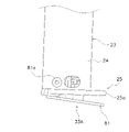
- It is a partial side view which shows an arm lower part, a hook, and a contact sensor.
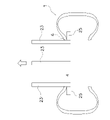
- It is a schematic diagram which shows one state of tire lifting operation
- It is a schematic diagram which shows one state of tire lifting operation
- It is a schematic diagram which shows one state of tire lifting operation
- It is a block diagram which shows the control structure of a tire conveying apparatus.
- FIG. 4 is a flow chart showing a tire lifting control operation of the tire conveying device; 4 is a flow chart showing a tire lifting control operation of the tire conveying device; FIG. 4 is a schematic plan view showing one state of the positional relationship between the tire and the laser distance sensor; FIG. 4 is a schematic plan view showing one state of the positional relationship between the tire and the laser distance sensor; FIG. 4 is a schematic plan view showing one state of the positional relationship between the tire and the laser distance sensor;
- FIG. 1 is a schematic front view of a tire conveying device.
- the tire transporting device 1 is a device or facility that transports the tire T while it is suspended horizontally (a state in which the meridian cross section of the tire is substantially horizontal). Specifically, the tire T is moved or stacked. or tiered.
- the direction perpendicular to the plane of FIG. 1 is the first direction (arrow X), and the horizontal direction of FIG. 1 is the second direction (arrow Y).
- the vertical direction is indicated by arrow Z.
- the tire T is a rubber hollow member provided with a center hole 4 (FIG. 2).
- the tire transporting device 1 has a structure also called a gantry crane, and has a pair of first rails 3 , a second rail 5 , and a moving unit 7 .
- the pair of first rails 3 are placed above the ground and extend parallel to each other in the first direction, and are separated from each other in the second direction.
- the second rail 5 extends in the second direction so as to span the pair of first rails 3 , and is driven by an X-axis driving device 71 ( FIG. 9 ) to extend along the pair of first rails 3 . It is movable in a first direction.
- the moving unit 7 is supported by the second rail 5 and is movable along the second rail 5 in the second direction by being driven by the Y-axis driving device 73 (FIG. 9).
- the tire transport device 1 has a gripper device 9 .
- the gripper device 9 is a device that is attached to the moving unit 7 so as to be able to move up and down, and that grips and transfers the tire T. As shown in FIG. Specifically, the gripper device 9 grips the tire T from the inside and lifts it upward, and then horizontally moves and transfers it.
- the tire conveying device 1 has a Z-axis driving device 75 .
- the Z-axis driving device 75 is a mechanism for raising and lowering the gripper device 9 attached to its lower part.
- the Z-axis driving device 75 is a known technology, and includes, for example, a belt (not shown) that suspends and supports the gripper device 9, and a hoisting device that lifts and lowers the gripper device 9 by winding/rewinding the belt. is doing.
- the gripper device 9 has a base 21 fixed to the Z-axis drive device 75 and three arms 23 extending vertically downward from the base 21 .
- the base 21 is an elevating table, and is vertically suspended from the moving unit 7 by a belt (not shown) of the Z-axis driving device 75 .
- the three arms 23 are arranged at equal intervals in the circumferential direction at an angle of 120° on a predetermined circumference.
- a hook 25 is provided at the lower end of the arm body 24 of each arm 23 so as to protrude outward in the horizontal direction.
- the hook 25 engages the bead portion on the upper side of the tire T from below.
- a touch sensor (not shown) may be attached to the outward side surface of the arm 23 . This touch sensor is for detecting that the main body of the arm 23 comes into contact with the upper opening edge of the center hole 4 of the tire T when the arm 23 is moved outward.
- the gripper device 9 has an arm expanding and contracting device 77 (FIG. 9).
- the arm expansion/contraction device 77 is a chuck device that radially expands/contracts the three arms 23 in the horizontal direction (switches between an expanded state and a contracted state).
- the arm expanding/contracting device 77 is provided on the base 21 .
- the arm expanding/contracting device 77 is a well-known technique, and includes, for example, a chuck cylinder (not shown) and an interlocking mechanism (not shown) that interlocks the arms 23 .
- the arm 23 is circumferentially furthest from the adjacent arm 23 at the enlarged diameter position, and is circumferentially closest to the adjacent arm 23 at the diameter reduced position.
- the gripper device 9 has a first laser distance sensor 31A, a second laser distance sensor 31B and a third laser distance sensor 31C.
- the first to third laser distance sensors 31A to 31C are for detecting the distance in the height direction between an object below and the base 21 of the gripper device 9 .
- the first to third laser distance sensors 31A to 31C are provided at the bottom of the base 21 and emit laser light directly downward, that is, downward in the vertical direction. As shown in FIGS. 2 and 3, the first to third laser distance sensors 31A to 31C are arranged between the hooks 25 in the circumferential direction. placed at an angle.
- the first to third laser distance sensors 31A to 31C are arranged outside the first circle C1 including the tip of the hook 25 when the arm 23 is contracted to the maximum (an example of the diameter-reduced state).
- the first to third laser distance sensors 31A-31C are arranged close to the first circle C1.
- the first to third laser distance sensors 31A to 31C are arranged between the first circle C1 and the second circle C2 including the tip of the hook 25 when the arm 23 is expanded most (an example of the expanded diameter state). It is good if it is. That is, the first to third laser distance sensors 31A to 31C are arranged outside the first circle C1 and inside the second circle C2.
- first to third laser distance sensors 31A to 31C may be provided radially outwardly away from the first circle C1. Also, the first to third laser distance sensors 31A to 31C do not have to be arranged in the circumferential direction. That is, the first to third laser distance sensors 31A to 31C may be arranged at different distances from the center.
- the first to third laser distance sensors 31A to 31C are arranged outside the first circle C1 including the tip of the hook 25 when the arm 23 is above the tire T and the diameter is reduced. Detect objects below.
- the gripper device 9 has first to third contact sensors 33A to 33C (FIG. 9) which are provided on the lower surface of the hook 25 and whose tip side of the hook 25 moves up and down.
- the first to third contact sensors 33A to 33C are sensors for detecting when the bottom surface of the hook 25 collides with the upper surface of the tire T while the arm 23 is descending.
- the first contact sensor 33A will be described with reference to FIG.
- FIG. 4 is a partial side view showing the arm lower portion, the hook, and the contact sensor.
- the first contact sensor 33A has a vertically rotating plate 81 .
- the base side of the plate 81 is supported below the arm 23 by a rotating shaft 81a extending horizontally.
- the plate 81 is movable between a horizontal position in contact with the main body 25a of the hook 25 and an oblique position in which the tip portion is spaced downward.
- the first contact sensor 33A has a spring (not shown, for example, a coil spring) that elastically urges the plate 81 downward in the rotational direction. Plate 81 is therefore normally in an oblique position.
- the first contact sensor 33A has a load sensor (not shown). The load sensor is provided at a position where it is compressed between the plate 81 and other members of the hook 25 when the plate 81 contacts an object below and rotates upward to move to a horizontal position.
- FIG. 5 to 8 are schematic diagrams showing one state of the tire lifting operation. First, as shown in FIG. 5, the gripper device 9 is placed directly above the tire T (that is, directly above the center hole).
- the three arms 23 are lowered in a contracted state and inserted into the upper opening edge 6, and the tip of the hook 25 is positioned near the center of the tire T in the vertical direction.
- the three arms 23 are expanded in the tire radial direction and moved to positions where the hooks 25 engage the upper opening edge 6 (bead portion) of the tire T in plan view.
- FIG. 9 is a block diagram showing the control configuration of the tire conveying device.
- the tire conveying device 1 has a controller 51 .
- the controller 51 is a computer having a processor (eg, CPU), a storage device (eg, ROM, RAM, HDD, SSD, etc.), and various interfaces (eg, A/D converter, D/A converter, communication interface, etc.). system.
- the controller 51 performs various control operations by executing programs stored in a storage unit (corresponding to part or all of the storage area of the storage device).
- the controller 51 may be composed of a single processor, or may be composed of a plurality of independent processors for each control.
- a part or all of the function of each element of the controller 51 may be implemented as a program executable by the computer system that configures the controller 51 .
- part of the function of each element of the controller 51 may be configured by a custom IC.
- An X-axis driving device 71 , a Y-axis driving device 73 , a Z-axis driving device 75 and an arm expanding/contracting device 77 are connected to the controller 51 .
- a controller 51 can control these devices.
- Connected to the controller 51 are first to third laser distance sensors 31A to 31C and first to third contact sensors 33A to 33C. Detection signals are input to the controller 51 from these sensors.
- the controller 51 is connected to sensors and switches for detecting the state of each device, and an information input device.
- FIG. 10 and 11 are flowcharts showing the tire lifting control operation of the tire conveying device.
- 12 to 14 are schematic plan views showing one state of the positional relationship between the tire and the laser distance sensor.
- the control flow chart described below is an example, and each step can be omitted or replaced as needed. Also, a plurality of steps may be executed simultaneously, or some or all of them may overlap.
- each block in the control flow chart is not limited to a single control operation, and can be replaced with a plurality of control operations represented by a plurality of blocks.
- the operation of each device is the result of commands from the control section to each device, and these are expressed by each step of the software application.
- step S1 the moving unit 7 is moved to just above the position where the tire T is placed and stopped.
- the controller 51 controls the X-axis driving device 71 and the Y-axis driving device 73 to execute the above operations. Note that the position of the tire T is stored in advance in the storage section of the controller 51 .
- step S2 each arm 23 is moved to the innermost position (that is, the diameter is reduced). Specifically, the controller 51 controls the arm expanding/contracting device 77 to execute the above operation. In addition, when each arm 23 is in the contracted state from the beginning, the above operation is omitted.
- step S3 the gripper device 9 is lowered to a predetermined height.
- the controller 51 controls the Z-axis driving device 75 to execute the above operation.
- the above predetermined height is, for example, the height at which the height direction distance between the lower bottom surface of the arm 23 and the top surface of the tire T becomes a predetermined value (eg, 300 mm). Note that the height of the top surface of the tire T is stored in advance in the storage section of the controller 51 .
- step S4 the first to third laser distance sensors 31A to 31C irradiate a laser downward, receive the reflected laser light, and detect the distance to the object below.
- the gripper device 9 is lowered as described above and the distances between the first to third laser distance sensors 31A to 31C and the tire T are close, detection accuracy is enhanced.
- step S5 it is determined whether or not the distances to the object below the first to third laser distance sensors 31A to 31C are different from each other. If Yes, the process moves to step S6, and if No, the process moves to step S9. If Yes in step S5, two of the first to third laser distance sensors 31A to 31C are directly above the center hole 4 of the tire T, but one is located above the tire T, as shown in FIG. This is the case where the measurement distance is shorter than the other two because it is located directly above. This is the case when the position of the arm 23 is inappropriate, and one hook 25 hits the tire T when the arm 23 is lowered. No in step S5 means that all of the first to third laser distance sensors 31A to 31C are directly above the center hole 4 of the tire T, as shown in FIG.
- step S6 it is determined whether or not the above determination has exceeded a predetermined number of times. If yes, the process moves to step S8. If No, the process moves to S7.
- step S7 the gripper device 9 is moved horizontally.
- the moving distance is, for example, 5 to 10 mm.
- the controller 51 as indicated by the white arrows in FIG.
- the gripper device 9 or arm 23 is also moved inwards (eg, in a direction toward the center of the circumference), after which the distances measured by the first to third laser distance sensors 31A-31C are monitored. Therefore, the position of arm 23 is corrected. As a result, the arm 23 is less likely to come into contact with the tire T.
- step S7 ends, the process returns to step S4.
- the controller 51 As shown in FIG. 14, when two of the first to third laser distance sensors 31A to 31C are directly above the tire T and the measured distance is shorter than the other one, the controller 51 , the gripper device 9, that is, arm 23 is also moved.
- step S8 Abnormality processing is performed in step S8. Specifically, an anomaly warning is issued. Thereafter, the operator takes measures to eliminate the abnormal state by manual operation, manual work, or the like. In step S9, a tire holding/lifting operation is performed (described later).
- the controller 51 monitors the distances measured by the first to third laser distance sensors 31A to 31C, and if the tire T is not detected, the Z-axis driving device 75 lowers the arm The tire T is held. On the other hand, the controller 51 causes a difference between the distances measured by the first to third laser distance sensors 31A to 31C (that is, one of the first to third laser distance sensors 31A to 31C detects the tire T). , the Z-axis driving device 75 does not lower the arm 23 . This means that when at least one of the first to third laser distance sensors 31A to 31C detects the tire T, the distance measured by that sensor is the shortest, and the tire T exists directly below.
- the tire T is arranged at a position overlapping the hook 25 in plan view (for example, the tire T is tilted or positioned differently). That is, the controller 51 determines that the position of the arm 23 is inappropriate. Further, as described above, when at least one of the first to third laser distance sensors 31A to 31C is not inside the center hole 4 of the tire T in plan view, the planar position of the gripper device 9 is corrected and downwardly adjusted. Re-measurement of the distance is repeatedly performed. That is, if the measured distances are different (Yes in step S5), the gripper device 9 is moved by a predetermined distance (for example, several millimeters) in step S7, and the distance to the tire T is remeasured in step S5. Note that the measured distances differ when, for example, they exceed a predetermined value such as 30 to 50 mm.
- Step S9 in FIG. 10 will be described in detail with reference to FIG.
- the gripper device 9 starts to descend from the state shown in FIG. 5, for example.
- the controller 51 controls the Z-axis driving device 75 to execute the above operation.
- step S12 it is determined whether or not at least one of the first to third contact sensors 33A to 33C has turned ON. Specifically, the controller 51 makes the determination based on the detection signals from the first to third contact sensors 33A to 33C. If Yes, the process moves to step S17, and if No, the process moves to step S13.
- step S13 it is determined whether or not the gripper device 9 has reached a predetermined height position. Specifically, the controller 51 makes the above determination based on a detection signal from a sensor (not shown). If Yes, the process moves to step S14, and if No, the process returns to step S12.
- step S14 the lowering of the gripper device 9 is stopped (for example, the state of FIG. 6). Specifically, the controller 51 controls the Z-axis driving device 75 to execute the above operation.
- step S15 the three arms 23 are moved radially outward (for example, the state of FIG. 7). Specifically, the controller 51 controls the arm expanding/contracting device 77 to execute the above operation. Thereby, the hook 25 is positioned below the upper opening edge 6 of the center hole 4 of the tire T. As shown in FIG. The movement of the three arms 23 is stopped according to a detection signal from a touch sensor or the like when the main body of the arms 23 comes into contact with the upper opening edge of the center hole 4 of the tire T. As shown in FIG.
- step S16 the gripper device 9 is raised (for example, the state of FIG. 8). Specifically, the controller 51 controls the Z-axis driving device 75 to execute the above operation. As a result, each arm 23 rises, and the hook 25 of each arm 23 supports the upper opening edge of the center hole 4 of the tire T from below, thereby lifting the tire T as a whole.
- step S17 abnormality processing is performed. Specifically, further descent of the arm 23 is stopped. Further, an abnormality alarm is issued, and thereafter the operator takes measures to eliminate the abnormal state by manual operation, manual work, or the like.
- the first to third contact sensors 33A to 33C detects the tire T in this manner, unlike when at least one of the first to third laser distance sensors 31A to 31C detects the tire T, Abnormal processing is performed immediately without performing position correction. This is because, in the above case, it is considered that the tire T is in a state that cannot be dealt with even by adjustment such as positional correction.
- the controller 51 determines how many stages from the top the tire T is transported based on the detection results of the first to third laser distance sensors 31A to 31C. determine if it is possible. Then, if there are tires T that can be transported, the process proceeds to step S9, and tire holding/lifting operations are performed. In the tire holding/lifting operation described above, the transportable amount of the tires T may be transported together, or the tires T may be transported one by one.
- the lower tire T is conveyed.
- the tire T can also be transported. As a result, only the transportable number of tires T can be transported when there is a difference between the distances measured by the first to third laser distance sensors 31A to 31C. Therefore, the transportation efficiency of the tire T is improved.
- the tire T has three stages, the tire width is 200 mm, and the total height of the three stages is 600 mm. Note that the controller 51 recognizes that the tires T are stacked in three layers based on the inventory data. First, at 300 mm above the tire T, the distance to the tire T is detected by the first to third laser distance sensors 31A to 31C, as in steps S4 and S5 of FIG.
- step S7 in FIG. 10 when the correction operation in step S7 in FIG. 10 is performed once, but the difference in distance cannot be resolved, and then there is a difference in distance again in step S5 (Yes in step S5), the controller At step 51, as a new step, based on the detection results of the first to third laser distance sensors 31A to 31C, it is determined to which tier from the top the tire T can be transported.
- the detection result of two sensors is 900 mm (the tire T is not detected), and the detection result of one sensor is 700 mm (the lowest tire T is detected). and
- the controller 51 determines that the two tires T from the top can be transferred. This is the case, for example, when the lowermost tire T is in the correct position, but the upper tire T is tilted and causes the difference in detection distance as described above. Then, in step S9 of FIG. 10, the upper two stages of tires T are transported.
- the mobile unit 7 returns directly above the position where the lowest tire T is placed.
- the tire conveying device 1 detects the tire T on the lowest stage and conveys the tire T next.
- a tire conveying device 1 (an example of a tire conveying device) is a device for lifting and conveying a tire T, and includes at least three arms 23, an arm expanding/contracting device 77, a Z-axis driving device 75, and a controller 51. and
- the three arms 23 (an example of arms) are provided on an arm body 24 (an example of an arm body) and on the lower portion of the arm body 24 so as to protrude outward. example).
- An arm expansion/contraction device 77 (an example of an arm expansion/contraction mechanism) moves the arm 23 in a horizontal expansion/contraction direction.
- a Z-axis drive device 75 (an example of an elevating mechanism) elevates the arm 23 .
- the first to third laser distance sensors 31A to 31C are arranged outside a first circle C1 (an example of a circle) including the tip of the hook 25 when the arm 23 is above the tire T and the diameter is reduced, Detect objects below.
- the controller 51 determines that the position of the arm 23 is inappropriate when the tire T is detected by at least one of the first to third laser distance sensors 31A to 31C.
- the first to third laser distance sensors 31A to 31C detect the tire T, it means that the tire T is arranged at a position overlapping the hook 25 in plan view. In this case, for example, since the Z-axis driving device does not lower the arm 23, the hook 25 does not contact the tire T even if the tire T is tilted or the position is different.
- Three or more laser distance sensors for example, four, five, or six, may be used.
- a reflective photoelectric sensor that detects the presence or absence of a reflecting object may be used instead of the laser distance sensor.
- the presence or absence of the tire T directly below the sensor can be detected, and the controller can distinguish between the presence and absence of the tire T. It is not necessary to lower the gripper device prior to detection by the laser distance sensor. Further, detection by the laser distance sensor may be performed while the gripper device is being lowered.
- (4) Modified example of contact sensor The type, structure, number, etc.
- the contact sensor includes a contact member that moves up and down, a linear motion guide that guides the contact member in the vertical direction, a spring that biases the contact member downward, and a contact member that contacts the lower member. It may have a load sensor that is compressed between the abutment member and the other member of the hook as it moves upwardly. A contact sensor may be omitted.
- the tire conveying apparatus is not limited to a gantry crane, and may be provided in an overhead conveying vehicle that travels at a predetermined height position.
- the present invention can be widely applied to a device that lifts a tire by inserting a plurality of arms from above into the upper opening edge of the center hole of the tire lying on its side and supporting the upper opening edge from below with the hooks of the arms.
- Reference Signs List 1 Tire conveying device 3 : First rail 5 : Second rail 7 : Moving unit 9 : Gripper device 21 : Base 23 : Arm 25 : Hook 31A : First laser distance sensor 31B : Second laser distance sensor 31C : Third Laser distance sensor 33A: First contact sensor 33B: Second contact sensor 33C: Third contact sensor 51: Controller 71: X-axis driving device 73: Y-axis driving device 75: Z-axis driving device 77: Arm expansion/contraction device
Landscapes
- Engineering & Computer Science (AREA)
- Mechanical Engineering (AREA)
- Automation & Control Theory (AREA)
- Manipulator (AREA)
- Load-Engaging Elements For Cranes (AREA)
- Carriers, Traveling Bodies, And Overhead Traveling Cranes (AREA)
- Length Measuring Devices By Optical Means (AREA)
- Tyre Moulding (AREA)
Priority Applications (5)
| Application Number | Priority Date | Filing Date | Title |
|---|---|---|---|
| EP21921195.0A EP4253301B1 (en) | 2021-01-21 | 2021-11-11 | Tire transport apparatus |
| KR1020237021683A KR102843523B1 (ko) | 2021-01-21 | 2021-11-11 | 타이어 반송 장치 |
| US18/273,050 US12378084B2 (en) | 2021-01-21 | 2021-11-11 | Tire transport apparatus |
| JP2022576993A JP7448040B2 (ja) | 2021-01-21 | 2021-11-11 | タイヤ搬送装置 |
| CN202180087797.1A CN116710386B (zh) | 2021-01-21 | 2021-11-11 | 轮胎搬送装置 |
Applications Claiming Priority (2)
| Application Number | Priority Date | Filing Date | Title |
|---|---|---|---|
| JP2021008143 | 2021-01-21 | ||
| JP2021-008143 | 2021-01-21 |
Publications (1)
| Publication Number | Publication Date |
|---|---|
| WO2022158092A1 true WO2022158092A1 (ja) | 2022-07-28 |
Family
ID=82548738
Family Applications (1)
| Application Number | Title | Priority Date | Filing Date |
|---|---|---|---|
| PCT/JP2021/041586 Ceased WO2022158092A1 (ja) | 2021-01-21 | 2021-11-11 | タイヤ搬送装置 |
Country Status (6)
| Country | Link |
|---|---|
| US (1) | US12378084B2 (https=) |
| EP (1) | EP4253301B1 (https=) |
| JP (1) | JP7448040B2 (https=) |
| KR (1) | KR102843523B1 (https=) |
| CN (1) | CN116710386B (https=) |
| WO (1) | WO2022158092A1 (https=) |
Cited By (1)
| Publication number | Priority date | Publication date | Assignee | Title |
|---|---|---|---|---|
| CN116621018A (zh) * | 2023-05-31 | 2023-08-22 | 荣成荣鹰橡胶制品有限公司 | 一种实心轮胎夹持转运装置及使用方法 |
Citations (4)
| Publication number | Priority date | Publication date | Assignee | Title |
|---|---|---|---|---|
| JP2004238147A (ja) * | 2003-02-06 | 2004-08-26 | Okura Yusoki Co Ltd | 把持装置および移載機 |
| JP2008162733A (ja) | 2006-12-27 | 2008-07-17 | Murata Mach Ltd | 物品移載装置 |
| WO2020105268A1 (ja) * | 2018-11-19 | 2020-05-28 | 村田機械株式会社 | 姿勢転換装置 |
| WO2020242294A1 (en) * | 2019-05-28 | 2020-12-03 | Vmi Holland B.V. | Bead-apex storage system and method for handling a plurality of stacks with bead-apexes and spacers |
Family Cites Families (22)
| Publication number | Priority date | Publication date | Assignee | Title |
|---|---|---|---|---|
| JPS597032A (ja) * | 1982-07-06 | 1984-01-14 | Mitsubishi Heavy Ind Ltd | 生タイヤの供給装置 |
| JP3136446B2 (ja) * | 1991-12-27 | 2001-02-19 | 横浜ゴム株式会社 | 加硫機へのグリーンタイヤの供給,角度調整方法 |
| JPH06126678A (ja) * | 1992-10-16 | 1994-05-10 | Kirin Brewery Co Ltd | 円筒形容器把持装置 |
| JPH06183682A (ja) * | 1992-12-17 | 1994-07-05 | Mitsubishi Heavy Ind Ltd | タイヤ等リング状部材搬送用吊具 |
| JPH0761602A (ja) * | 1993-08-27 | 1995-03-07 | Mitsubishi Heavy Ind Ltd | タイヤ移載装置 |
| JP2003020190A (ja) * | 2001-07-11 | 2003-01-21 | Nippon Yusoki Co Ltd | ロール吊上装置 |
| JP4224784B2 (ja) * | 2003-07-18 | 2009-02-18 | 株式会社ダイフク | 把持部昇降式搬送装置 |
| JP4941451B2 (ja) * | 2008-10-20 | 2012-05-30 | 三菱自動車工業株式会社 | タイヤ把持装置 |
| EP2792474B1 (en) * | 2011-12-16 | 2017-03-08 | Bridgestone Corporation | Tire printing method and tire printing device |
| US9428334B2 (en) * | 2013-05-17 | 2016-08-30 | The Heil Co. | Automatic control of a refuse front end loader |
| CN203422070U (zh) * | 2013-08-14 | 2014-02-05 | 贵州轮胎股份有限公司 | 轮胎特定点角度与方向检测装置 |
| JP6240689B2 (ja) * | 2015-07-31 | 2017-11-29 | ファナック株式会社 | 人の行動パターンを学習する機械学習装置、ロボット制御装置、ロボットシステム、および機械学習方法 |
| CN204872926U (zh) * | 2015-08-28 | 2015-12-16 | 山东昊华轮胎有限公司 | 一种全钢载重子午线轮胎堆垛机 |
| JP6567388B2 (ja) * | 2015-10-20 | 2019-08-28 | 株式会社小野測器 | タイヤ装着システム |
| EP3460834B1 (en) * | 2016-05-20 | 2020-08-05 | Murata Machinery, Ltd. | Transport vehicle and transport method |
| CN107098260B (zh) * | 2017-06-08 | 2018-06-22 | 北京天朔新能源汽车有限公司 | 一种电动汽车专用橡胶轮胎自动吊运机器人 |
| WO2019049511A1 (ja) * | 2017-09-05 | 2019-03-14 | 住友重機械搬送システム株式会社 | クレーン装置 |
| JP7135411B2 (ja) * | 2018-05-02 | 2022-09-13 | 村田機械株式会社 | 搬送システム |
| CA3129088A1 (en) * | 2019-02-04 | 2020-08-13 | The Heil Co. | Semi-autonomous refuse collection |
| CA3137481A1 (en) * | 2019-04-23 | 2020-10-29 | The Heil Co. | Refuse container engagement |
| WO2020219769A1 (en) * | 2019-04-23 | 2020-10-29 | The Heil Co. | Refuse collection vehicle controls |
| WO2021157117A1 (ja) * | 2020-02-06 | 2021-08-12 | 村田機械株式会社 | 挟持装置及び段積み装置 |
-
2021
- 2021-11-11 JP JP2022576993A patent/JP7448040B2/ja active Active
- 2021-11-11 CN CN202180087797.1A patent/CN116710386B/zh active Active
- 2021-11-11 EP EP21921195.0A patent/EP4253301B1/en active Active
- 2021-11-11 US US18/273,050 patent/US12378084B2/en active Active
- 2021-11-11 WO PCT/JP2021/041586 patent/WO2022158092A1/ja not_active Ceased
- 2021-11-11 KR KR1020237021683A patent/KR102843523B1/ko active Active
Patent Citations (4)
| Publication number | Priority date | Publication date | Assignee | Title |
|---|---|---|---|---|
| JP2004238147A (ja) * | 2003-02-06 | 2004-08-26 | Okura Yusoki Co Ltd | 把持装置および移載機 |
| JP2008162733A (ja) | 2006-12-27 | 2008-07-17 | Murata Mach Ltd | 物品移載装置 |
| WO2020105268A1 (ja) * | 2018-11-19 | 2020-05-28 | 村田機械株式会社 | 姿勢転換装置 |
| WO2020242294A1 (en) * | 2019-05-28 | 2020-12-03 | Vmi Holland B.V. | Bead-apex storage system and method for handling a plurality of stacks with bead-apexes and spacers |
Cited By (2)
| Publication number | Priority date | Publication date | Assignee | Title |
|---|---|---|---|---|
| CN116621018A (zh) * | 2023-05-31 | 2023-08-22 | 荣成荣鹰橡胶制品有限公司 | 一种实心轮胎夹持转运装置及使用方法 |
| CN116621018B (zh) * | 2023-05-31 | 2023-12-22 | 荣成荣鹰橡胶制品有限公司 | 一种实心轮胎夹持转运装置及使用方法 |
Also Published As
| Publication number | Publication date |
|---|---|
| KR20230111239A (ko) | 2023-07-25 |
| JP7448040B2 (ja) | 2024-03-12 |
| CN116710386A (zh) | 2023-09-05 |
| EP4253301B1 (en) | 2026-04-22 |
| US12378084B2 (en) | 2025-08-05 |
| CN116710386B (zh) | 2026-03-27 |
| EP4253301A1 (en) | 2023-10-04 |
| KR102843523B1 (ko) | 2025-08-07 |
| US20240083695A1 (en) | 2024-03-14 |
| EP4253301A4 (en) | 2024-10-30 |
| JPWO2022158092A1 (https=) | 2022-07-28 |
Similar Documents
| Publication | Publication Date | Title |
|---|---|---|
| US10730708B2 (en) | Unloading apparatus and unloading method | |
| US9067744B2 (en) | Robot system, robot, and sorted article manufacturing method | |
| JP6007880B2 (ja) | 天井搬送車 | |
| JP2015047681A (ja) | ロボットハンド、ロボットシステム、物品のデパレタイズ方法 | |
| US20180111757A1 (en) | Article Transport Facility | |
| JP2008044732A (ja) | 物品収納設備 | |
| WO2018066230A1 (ja) | 搬送装置、及び搬送方法 | |
| US10134620B2 (en) | Robot system and incline detection method | |
| JP2019116336A (ja) | 回転式ストッカ及びそれを備える移送システム | |
| JP5082437B2 (ja) | 物品移載装置 | |
| WO2022158092A1 (ja) | タイヤ搬送装置 | |
| JP2008247558A (ja) | 物品搬送装置 | |
| EP4330163A1 (en) | Container handler and method for handling a storage container | |
| JP5765577B2 (ja) | スタッカークレーン | |
| JP5190694B2 (ja) | 物品収納設備における学習装置 | |
| JP2541431B2 (ja) | スタッカクレ―ン | |
| CN118458301A (zh) | 位置校正装置以及位置校正方法 | |
| JP4973927B2 (ja) | 物品搬送装置 | |
| JP6795361B2 (ja) | 搬送設備 | |
| JP2012046327A (ja) | 移載装置および先入品判断方法 | |
| JP6673305B2 (ja) | 自動倉庫システム | |
| JP6932984B2 (ja) | 生タイヤの搬送システム | |
| JPH07251943A (ja) | 荷扱い方法及びその装置 | |
| JP2021123472A (ja) | 保持装置 | |
| JP7528695B2 (ja) | 荷役装置及び荷役装置の運転方法 |
Legal Events
| Date | Code | Title | Description |
|---|---|---|---|
| 121 | Ep: the epo has been informed by wipo that ep was designated in this application |
Ref document number: 21921195 Country of ref document: EP Kind code of ref document: A1 |
|
| ENP | Entry into the national phase |
Ref document number: 2022576993 Country of ref document: JP Kind code of ref document: A |
|
| ENP | Entry into the national phase |
Ref document number: 20237021683 Country of ref document: KR Kind code of ref document: A |
|
| WWE | Wipo information: entry into national phase |
Ref document number: 202180087797.1 Country of ref document: CN |
|
| ENP | Entry into the national phase |
Ref document number: 2021921195 Country of ref document: EP Effective date: 20230627 |
|
| WWE | Wipo information: entry into national phase |
Ref document number: 18273050 Country of ref document: US |
|
| NENP | Non-entry into the national phase |
Ref country code: DE |
|
| WWG | Wipo information: grant in national office |
Ref document number: 18273050 Country of ref document: US |
|
| WWG | Wipo information: grant in national office |
Ref document number: 2021921195 Country of ref document: EP |