WO2022154120A1 - 印画物の製造方法、印画物及び熱転写シート - Google Patents
印画物の製造方法、印画物及び熱転写シート Download PDFInfo
- Publication number
- WO2022154120A1 WO2022154120A1 PCT/JP2022/001399 JP2022001399W WO2022154120A1 WO 2022154120 A1 WO2022154120 A1 WO 2022154120A1 JP 2022001399 W JP2022001399 W JP 2022001399W WO 2022154120 A1 WO2022154120 A1 WO 2022154120A1
- Authority
- WO
- WIPO (PCT)
- Prior art keywords
- layer
- transfer sheet
- thermal transfer
- base material
- printed matter
- Prior art date
Links
- 238000012546 transfer Methods 0.000 title claims abstract description 242
- 238000000034 method Methods 0.000 title claims abstract description 30
- 238000004519 manufacturing process Methods 0.000 title claims abstract description 28
- 239000000463 material Substances 0.000 claims abstract description 85
- 239000006260 foam Substances 0.000 claims abstract description 63
- 239000002245 particle Substances 0.000 claims abstract description 62
- 238000010438 heat treatment Methods 0.000 claims abstract description 18
- 239000010410 layer Substances 0.000 claims description 306
- 229920005989 resin Polymers 0.000 claims description 53
- 239000011347 resin Substances 0.000 claims description 53
- 239000012790 adhesive layer Substances 0.000 claims description 39
- 230000009477 glass transition Effects 0.000 claims description 26
- 239000011230 binding agent Substances 0.000 claims description 23
- 238000004040 coloring Methods 0.000 claims description 14
- 238000000926 separation method Methods 0.000 abstract 1
- 238000005187 foaming Methods 0.000 description 38
- 239000011248 coating agent Substances 0.000 description 36
- 238000000576 coating method Methods 0.000 description 36
- 239000007788 liquid Substances 0.000 description 36
- 239000000203 mixture Substances 0.000 description 22
- 229920000728 polyester Polymers 0.000 description 21
- -1 polypropylene Polymers 0.000 description 14
- 238000002360 preparation method Methods 0.000 description 14
- 238000001035 drying Methods 0.000 description 12
- 239000004088 foaming agent Substances 0.000 description 12
- XLYOFNOQVPJJNP-UHFFFAOYSA-N water Substances O XLYOFNOQVPJJNP-UHFFFAOYSA-N 0.000 description 12
- 239000004005 microsphere Substances 0.000 description 11
- 238000011156 evaluation Methods 0.000 description 10
- 239000011241 protective layer Substances 0.000 description 9
- 229920002554 vinyl polymer Polymers 0.000 description 8
- ZWEHNKRNPOVVGH-UHFFFAOYSA-N 2-Butanone Chemical compound CCC(C)=O ZWEHNKRNPOVVGH-UHFFFAOYSA-N 0.000 description 6
- 239000004925 Acrylic resin Substances 0.000 description 6
- 229920000178 Acrylic resin Polymers 0.000 description 6
- YXFVVABEGXRONW-UHFFFAOYSA-N Toluene Chemical compound CC1=CC=CC=C1 YXFVVABEGXRONW-UHFFFAOYSA-N 0.000 description 6
- 239000011203 carbon fibre reinforced carbon Substances 0.000 description 6
- 230000000052 comparative effect Effects 0.000 description 6
- 239000000178 monomer Substances 0.000 description 6
- 125000000391 vinyl group Chemical group [H]C([*])=C([H])[H] 0.000 description 6
- 125000004432 carbon atom Chemical group C* 0.000 description 5
- 238000000859 sublimation Methods 0.000 description 5
- 230000008022 sublimation Effects 0.000 description 5
- 229920005992 thermoplastic resin Polymers 0.000 description 5
- 150000001875 compounds Chemical class 0.000 description 4
- 229920001577 copolymer Polymers 0.000 description 4
- 239000000975 dye Substances 0.000 description 4
- 229930195733 hydrocarbon Natural products 0.000 description 4
- 229920001187 thermosetting polymer Polymers 0.000 description 4
- 229920002799 BoPET Polymers 0.000 description 3
- YMWUJEATGCHHMB-UHFFFAOYSA-N Dichloromethane Chemical compound ClCCl YMWUJEATGCHHMB-UHFFFAOYSA-N 0.000 description 3
- 239000004793 Polystyrene Substances 0.000 description 3
- 125000003647 acryloyl group Chemical group O=C([*])C([H])=C([H])[H] 0.000 description 3
- 230000015572 biosynthetic process Effects 0.000 description 3
- 229920002678 cellulose Polymers 0.000 description 3
- 239000001913 cellulose Substances 0.000 description 3
- 239000012461 cellulose resin Substances 0.000 description 3
- 150000002430 hydrocarbons Chemical class 0.000 description 3
- 238000005259 measurement Methods 0.000 description 3
- VLKZOEOYAKHREP-UHFFFAOYSA-N n-Hexane Chemical compound CCCCCC VLKZOEOYAKHREP-UHFFFAOYSA-N 0.000 description 3
- OFBQJSOFQDEBGM-UHFFFAOYSA-N n-pentane Natural products CCCCC OFBQJSOFQDEBGM-UHFFFAOYSA-N 0.000 description 3
- 229920003229 poly(methyl methacrylate) Polymers 0.000 description 3
- 229920002037 poly(vinyl butyral) polymer Polymers 0.000 description 3
- 239000004926 polymethyl methacrylate Substances 0.000 description 3
- 229920002223 polystyrene Polymers 0.000 description 3
- 229920000915 polyvinyl chloride Polymers 0.000 description 3
- 239000004800 polyvinyl chloride Substances 0.000 description 3
- 239000000126 substance Substances 0.000 description 3
- 239000001993 wax Substances 0.000 description 3
- GWHJZXXIDMPWGX-UHFFFAOYSA-N 1,2,4-trimethylbenzene Chemical compound CC1=CC=C(C)C(C)=C1 GWHJZXXIDMPWGX-UHFFFAOYSA-N 0.000 description 2
- HEDRZPFGACZZDS-UHFFFAOYSA-N Chloroform Chemical compound ClC(Cl)Cl HEDRZPFGACZZDS-UHFFFAOYSA-N 0.000 description 2
- RTZKZFJDLAIYFH-UHFFFAOYSA-N Diethyl ether Chemical compound CCOCC RTZKZFJDLAIYFH-UHFFFAOYSA-N 0.000 description 2
- 239000001856 Ethyl cellulose Substances 0.000 description 2
- ZZSNKZQZMQGXPY-UHFFFAOYSA-N Ethyl cellulose Chemical compound CCOCC1OC(OC)C(OCC)C(OCC)C1OC1C(O)C(O)C(OC)C(CO)O1 ZZSNKZQZMQGXPY-UHFFFAOYSA-N 0.000 description 2
- IMNFDUFMRHMDMM-UHFFFAOYSA-N N-Heptane Chemical compound CCCCCCC IMNFDUFMRHMDMM-UHFFFAOYSA-N 0.000 description 2
- 239000004952 Polyamide Substances 0.000 description 2
- 239000004698 Polyethylene Substances 0.000 description 2
- 239000004743 Polypropylene Substances 0.000 description 2
- ATUOYWHBWRKTHZ-UHFFFAOYSA-N Propane Chemical compound CCC ATUOYWHBWRKTHZ-UHFFFAOYSA-N 0.000 description 2
- BZHJMEDXRYGGRV-UHFFFAOYSA-N Vinyl chloride Chemical compound ClC=C BZHJMEDXRYGGRV-UHFFFAOYSA-N 0.000 description 2
- DHKHKXVYLBGOIT-UHFFFAOYSA-N acetaldehyde Diethyl Acetal Natural products CCOC(C)OCC DHKHKXVYLBGOIT-UHFFFAOYSA-N 0.000 description 2
- 150000001241 acetals Chemical class 0.000 description 2
- 229920002301 cellulose acetate Polymers 0.000 description 2
- 239000002131 composite material Substances 0.000 description 2
- DIOQZVSQGTUSAI-UHFFFAOYSA-N decane Chemical compound CCCCCCCCCC DIOQZVSQGTUSAI-UHFFFAOYSA-N 0.000 description 2
- SNRUBQQJIBEYMU-UHFFFAOYSA-N dodecane Chemical compound CCCCCCCCCCCC SNRUBQQJIBEYMU-UHFFFAOYSA-N 0.000 description 2
- 238000005538 encapsulation Methods 0.000 description 2
- 239000003822 epoxy resin Substances 0.000 description 2
- 229920001249 ethyl cellulose Polymers 0.000 description 2
- 235000019325 ethyl cellulose Nutrition 0.000 description 2
- DCAYPVUWAIABOU-UHFFFAOYSA-N hexadecane Chemical compound CCCCCCCCCCCCCCCC DCAYPVUWAIABOU-UHFFFAOYSA-N 0.000 description 2
- 229920000554 ionomer Polymers 0.000 description 2
- 238000002156 mixing Methods 0.000 description 2
- 229920003023 plastic Polymers 0.000 description 2
- 239000004033 plastic Substances 0.000 description 2
- 229920002647 polyamide Polymers 0.000 description 2
- 229920001707 polybutylene terephthalate Polymers 0.000 description 2
- 239000004417 polycarbonate Substances 0.000 description 2
- 229920000515 polycarbonate Polymers 0.000 description 2
- 229920000647 polyepoxide Polymers 0.000 description 2
- 229920000573 polyethylene Polymers 0.000 description 2
- 229920000139 polyethylene terephthalate Polymers 0.000 description 2
- 239000005020 polyethylene terephthalate Substances 0.000 description 2
- 229920000642 polymer Polymers 0.000 description 2
- 238000006116 polymerization reaction Methods 0.000 description 2
- 229920000098 polyolefin Polymers 0.000 description 2
- 229920001155 polypropylene Polymers 0.000 description 2
- 229920002635 polyurethane Polymers 0.000 description 2
- 239000004814 polyurethane Substances 0.000 description 2
- 229920002689 polyvinyl acetate Polymers 0.000 description 2
- 239000011118 polyvinyl acetate Substances 0.000 description 2
- 150000004756 silanes Chemical class 0.000 description 2
- 229920002050 silicone resin Polymers 0.000 description 2
- 239000000758 substrate Substances 0.000 description 2
- VZGDMQKNWNREIO-UHFFFAOYSA-N tetrachloromethane Chemical compound ClC(Cl)(Cl)Cl VZGDMQKNWNREIO-UHFFFAOYSA-N 0.000 description 2
- 229920002803 thermoplastic polyurethane Polymers 0.000 description 2
- 238000013518 transcription Methods 0.000 description 2
- 230000035897 transcription Effects 0.000 description 2
- IIYFAKIEWZDVMP-UHFFFAOYSA-N tridecane Chemical compound CCCCCCCCCCCCC IIYFAKIEWZDVMP-UHFFFAOYSA-N 0.000 description 2
- RSJKGSCJYJTIGS-UHFFFAOYSA-N undecane Chemical compound CCCCCCCCCCC RSJKGSCJYJTIGS-UHFFFAOYSA-N 0.000 description 2
- OEPOKWHJYJXUGD-UHFFFAOYSA-N 2-(3-phenylmethoxyphenyl)-1,3-thiazole-4-carbaldehyde Chemical compound O=CC1=CSC(C=2C=C(OCC=3C=CC=CC=3)C=CC=2)=N1 OEPOKWHJYJXUGD-UHFFFAOYSA-N 0.000 description 1
- 125000003903 2-propenyl group Chemical group [H]C([*])([H])C([H])=C([H])[H] 0.000 description 1
- NBOCQTNZUPTTEI-UHFFFAOYSA-N 4-[4-(hydrazinesulfonyl)phenoxy]benzenesulfonohydrazide Chemical compound C1=CC(S(=O)(=O)NN)=CC=C1OC1=CC=C(S(=O)(=O)NN)C=C1 NBOCQTNZUPTTEI-UHFFFAOYSA-N 0.000 description 1
- FERIUCNNQQJTOY-UHFFFAOYSA-M Butyrate Chemical compound CCCC([O-])=O FERIUCNNQQJTOY-UHFFFAOYSA-M 0.000 description 1
- FERIUCNNQQJTOY-UHFFFAOYSA-N Butyric acid Natural products CCCC(O)=O FERIUCNNQQJTOY-UHFFFAOYSA-N 0.000 description 1
- 239000004215 Carbon black (E152) Substances 0.000 description 1
- 229920008347 Cellulose acetate propionate Polymers 0.000 description 1
- MWRWFPQBGSZWNV-UHFFFAOYSA-N Dinitrosopentamethylenetetramine Chemical compound C1N2CN(N=O)CN1CN(N=O)C2 MWRWFPQBGSZWNV-UHFFFAOYSA-N 0.000 description 1
- 229920000103 Expandable microsphere Polymers 0.000 description 1
- YCKRFDGAMUMZLT-UHFFFAOYSA-N Fluorine atom Chemical compound [F] YCKRFDGAMUMZLT-UHFFFAOYSA-N 0.000 description 1
- 239000000020 Nitrocellulose Substances 0.000 description 1
- 239000004677 Nylon Substances 0.000 description 1
- 239000004962 Polyamide-imide Substances 0.000 description 1
- 239000004695 Polyether sulfone Substances 0.000 description 1
- 239000004642 Polyimide Substances 0.000 description 1
- 239000004734 Polyphenylene sulfide Substances 0.000 description 1
- 229920001328 Polyvinylidene chloride Polymers 0.000 description 1
- PPBRXRYQALVLMV-UHFFFAOYSA-N Styrene Natural products C=CC1=CC=CC=C1 PPBRXRYQALVLMV-UHFFFAOYSA-N 0.000 description 1
- 229920002433 Vinyl chloride-vinyl acetate copolymer Polymers 0.000 description 1
- NIXOWILDQLNWCW-UHFFFAOYSA-N acrylic acid group Chemical group C(C=C)(=O)O NIXOWILDQLNWCW-UHFFFAOYSA-N 0.000 description 1
- 229920001893 acrylonitrile styrene Polymers 0.000 description 1
- 125000002723 alicyclic group Chemical group 0.000 description 1
- 125000001931 aliphatic group Chemical group 0.000 description 1
- 125000000217 alkyl group Chemical group 0.000 description 1
- XYLMUPLGERFSHI-UHFFFAOYSA-N alpha-Methylstyrene Chemical compound CC(=C)C1=CC=CC=C1 XYLMUPLGERFSHI-UHFFFAOYSA-N 0.000 description 1
- 125000003118 aryl group Chemical group 0.000 description 1
- 239000001273 butane Substances 0.000 description 1
- 229920006217 cellulose acetate butyrate Polymers 0.000 description 1
- NEHMKBQYUWJMIP-NJFSPNSNSA-N chloro(114C)methane Chemical compound [14CH3]Cl NEHMKBQYUWJMIP-NJFSPNSNSA-N 0.000 description 1
- 239000011258 core-shell material Substances 0.000 description 1
- OEBRKCOSUFCWJD-UHFFFAOYSA-N dichlorvos Chemical compound COP(=O)(OC)OC=C(Cl)Cl OEBRKCOSUFCWJD-UHFFFAOYSA-N 0.000 description 1
- 238000000113 differential scanning calorimetry Methods 0.000 description 1
- 238000004821 distillation Methods 0.000 description 1
- 238000009826 distribution Methods 0.000 description 1
- 238000010894 electron beam technology Methods 0.000 description 1
- 150000002148 esters Chemical class 0.000 description 1
- 125000005678 ethenylene group Chemical group [H]C([*:1])=C([H])[*:2] 0.000 description 1
- 125000001495 ethyl group Chemical group [H]C([H])([H])C([H])([H])* 0.000 description 1
- UKAJDOBPPOAZSS-UHFFFAOYSA-N ethyl(trimethyl)silane Chemical compound CC[Si](C)(C)C UKAJDOBPPOAZSS-UHFFFAOYSA-N 0.000 description 1
- 230000001747 exhibiting effect Effects 0.000 description 1
- 239000010419 fine particle Substances 0.000 description 1
- 229910052731 fluorine Inorganic materials 0.000 description 1
- 239000011737 fluorine Substances 0.000 description 1
- 230000005251 gamma ray Effects 0.000 description 1
- 239000012948 isocyanate Substances 0.000 description 1
- 239000000155 melt Substances 0.000 description 1
- 238000002844 melting Methods 0.000 description 1
- 230000008018 melting Effects 0.000 description 1
- 238000012986 modification Methods 0.000 description 1
- 230000004048 modification Effects 0.000 description 1
- IJDNQMDRQITEOD-UHFFFAOYSA-N n-butane Chemical compound CCCC IJDNQMDRQITEOD-UHFFFAOYSA-N 0.000 description 1
- 125000001624 naphthyl group Chemical group 0.000 description 1
- 239000000025 natural resin Substances 0.000 description 1
- 229920001220 nitrocellulos Polymers 0.000 description 1
- ZCYXXKJEDCHMGH-UHFFFAOYSA-N nonane Chemical compound CCCC[CH]CCCC ZCYXXKJEDCHMGH-UHFFFAOYSA-N 0.000 description 1
- BKIMMITUMNQMOS-UHFFFAOYSA-N normal nonane Natural products CCCCCCCCC BKIMMITUMNQMOS-UHFFFAOYSA-N 0.000 description 1
- 229920001778 nylon Polymers 0.000 description 1
- TVMXDCGIABBOFY-UHFFFAOYSA-N octane Chemical compound CCCCCCCC TVMXDCGIABBOFY-UHFFFAOYSA-N 0.000 description 1
- 239000012188 paraffin wax Substances 0.000 description 1
- 230000000149 penetrating effect Effects 0.000 description 1
- 239000013500 performance material Substances 0.000 description 1
- 239000003208 petroleum Substances 0.000 description 1
- 239000003209 petroleum derivative Substances 0.000 description 1
- 125000001997 phenyl group Chemical group [H]C1=C([H])C([H])=C(*)C([H])=C1[H] 0.000 description 1
- 239000000049 pigment Substances 0.000 description 1
- 229920001643 poly(ether ketone) Polymers 0.000 description 1
- 229920001483 poly(ethyl methacrylate) polymer Polymers 0.000 description 1
- 229920003207 poly(ethylene-2,6-naphthalate) Polymers 0.000 description 1
- 229920002401 polyacrylamide Polymers 0.000 description 1
- 229920000058 polyacrylate Polymers 0.000 description 1
- 229920006122 polyamide resin Polymers 0.000 description 1
- 229920002312 polyamide-imide Polymers 0.000 description 1
- 229920006393 polyether sulfone Polymers 0.000 description 1
- 229920000120 polyethyl acrylate Polymers 0.000 description 1
- 239000011112 polyethylene naphthalate Substances 0.000 description 1
- 229920001721 polyimide Polymers 0.000 description 1
- 229920000306 polymethylpentene Polymers 0.000 description 1
- 239000011116 polymethylpentene Substances 0.000 description 1
- 229920000069 polyphenylene sulfide Polymers 0.000 description 1
- 229920001296 polysiloxane Polymers 0.000 description 1
- 229920005749 polyurethane resin Polymers 0.000 description 1
- 229920002451 polyvinyl alcohol Polymers 0.000 description 1
- 235000019422 polyvinyl alcohol Nutrition 0.000 description 1
- 239000005033 polyvinylidene chloride Substances 0.000 description 1
- SCUZVMOVTVSBLE-UHFFFAOYSA-N prop-2-enenitrile;styrene Chemical compound C=CC#N.C=CC1=CC=CC=C1 SCUZVMOVTVSBLE-UHFFFAOYSA-N 0.000 description 1
- 239000001294 propane Substances 0.000 description 1
- 238000000746 purification Methods 0.000 description 1
- 150000003254 radicals Chemical class 0.000 description 1
- 230000009257 reactivity Effects 0.000 description 1
- 229920006395 saturated elastomer Polymers 0.000 description 1
- 239000007787 solid Substances 0.000 description 1
- 229920003002 synthetic resin Polymers 0.000 description 1
- 239000000057 synthetic resin Substances 0.000 description 1
- CZDYPVPMEAXLPK-UHFFFAOYSA-N tetramethylsilane Chemical compound C[Si](C)(C)C CZDYPVPMEAXLPK-UHFFFAOYSA-N 0.000 description 1
- 238000005979 thermal decomposition reaction Methods 0.000 description 1
- WDIWAJVQNKHNGJ-UHFFFAOYSA-N trimethyl(propan-2-yl)silane Chemical compound CC(C)[Si](C)(C)C WDIWAJVQNKHNGJ-UHFFFAOYSA-N 0.000 description 1
- WNWMJFBAIXMNOF-UHFFFAOYSA-N trimethyl(propyl)silane Chemical compound CCC[Si](C)(C)C WNWMJFBAIXMNOF-UHFFFAOYSA-N 0.000 description 1
- 229920006305 unsaturated polyester Polymers 0.000 description 1
- 150000003673 urethanes Chemical class 0.000 description 1
- 235000021419 vinegar Nutrition 0.000 description 1
- 239000000052 vinegar Substances 0.000 description 1
- XOOUIPVCVHRTMJ-UHFFFAOYSA-L zinc stearate Chemical compound [Zn+2].CCCCCCCCCCCCCCCCCC([O-])=O.CCCCCCCCCCCCCCCCCC([O-])=O XOOUIPVCVHRTMJ-UHFFFAOYSA-L 0.000 description 1
- PORPEXMDRRVVNF-UHFFFAOYSA-L zinc;octadecyl phosphate Chemical compound [Zn+2].CCCCCCCCCCCCCCCCCCOP([O-])([O-])=O PORPEXMDRRVVNF-UHFFFAOYSA-L 0.000 description 1
Images


Classifications
-
- B—PERFORMING OPERATIONS; TRANSPORTING
- B41—PRINTING; LINING MACHINES; TYPEWRITERS; STAMPS
- B41M—PRINTING, DUPLICATING, MARKING, OR COPYING PROCESSES; COLOUR PRINTING
- B41M5/00—Duplicating or marking methods; Sheet materials for use therein
- B41M5/26—Thermography ; Marking by high energetic means, e.g. laser otherwise than by burning, and characterised by the material used
- B41M5/382—Contact thermal transfer or sublimation processes
- B41M5/38207—Contact thermal transfer or sublimation processes characterised by aspects not provided for in groups B41M5/385 - B41M5/395
-
- B—PERFORMING OPERATIONS; TRANSPORTING
- B41—PRINTING; LINING MACHINES; TYPEWRITERS; STAMPS
- B41M—PRINTING, DUPLICATING, MARKING, OR COPYING PROCESSES; COLOUR PRINTING
- B41M5/00—Duplicating or marking methods; Sheet materials for use therein
- B41M5/26—Thermography ; Marking by high energetic means, e.g. laser otherwise than by burning, and characterised by the material used
- B41M5/382—Contact thermal transfer or sublimation processes
-
- B—PERFORMING OPERATIONS; TRANSPORTING
- B41—PRINTING; LINING MACHINES; TYPEWRITERS; STAMPS
- B41M—PRINTING, DUPLICATING, MARKING, OR COPYING PROCESSES; COLOUR PRINTING
- B41M5/00—Duplicating or marking methods; Sheet materials for use therein
- B41M5/26—Thermography ; Marking by high energetic means, e.g. laser otherwise than by burning, and characterised by the material used
- B41M5/40—Thermography ; Marking by high energetic means, e.g. laser otherwise than by burning, and characterised by the material used characterised by the base backcoat, intermediate, or covering layers, e.g. for thermal transfer dye-donor or dye-receiver sheets; Heat, radiation filtering or absorbing means or layers; combined with other image registration layers or compositions; Special originals for reproduction by thermography
-
- B—PERFORMING OPERATIONS; TRANSPORTING
- B41—PRINTING; LINING MACHINES; TYPEWRITERS; STAMPS
- B41M—PRINTING, DUPLICATING, MARKING, OR COPYING PROCESSES; COLOUR PRINTING
- B41M7/00—After-treatment of prints, e.g. heating, irradiating, setting of the ink, protection of the printed stock
- B41M7/009—After-treatment of prints, e.g. heating, irradiating, setting of the ink, protection of the printed stock using thermal means, e.g. infrared radiation, heat
Definitions
- This disclosure relates to a method for manufacturing a printed matter, a printed matter, and a thermal transfer sheet.
- the printed matter produced by the thermal transfer method has a wide variety of uses, for example, it is used for a card having a face photograph such as an ID card and a credit card, a composite photograph in an amusement facility, a trading card, and the like.
- the method for producing a printed matter of the present disclosure includes a step of preparing a thermal transfer sheet having a substrate and a transfer layer provided on one surface side of the substrate and having a layer containing foamed particles, and the thermal transfer.
- the printed matter of the present disclosure includes a transferred body and a laminated body provided on the transferred body and in which a plurality of transfer layers are laminated, and the plurality of the transfer layers are arranged in order from the transferred body side. It has a laminated adhesive layer and a layer containing foamed particles.
- the thermal transfer sheet of the present disclosure includes a base material and a plurality of transfer layers provided in a surface-sequential manner on one surface of the base material, and the plurality of transfer layers are each one of the base materials. It has a layer containing foam particles and an adhesive layer that are laminated in order from the surface side.
- thermal transfer sheet which concerns on embodiment. It is a process sectional view explaining the manufacturing method of a printed matter. It is a process sectional view explaining the manufacturing method of a printed matter. It is a process sectional view explaining the manufacturing method of a printed matter. It is a process sectional view explaining the manufacturing method of a printed matter. It is a process sectional view explaining the manufacturing method of the printed matter by a comparative example. It is a process sectional view explaining the manufacturing method of the printed matter by a comparative example. It is a process sectional view explaining the manufacturing method of the printed matter which concerns on another embodiment. It is a top view of the thermal transfer sheet. It is a process sectional view explaining the manufacturing method of the printed matter which concerns on another embodiment.
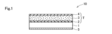
- FIG. 1 is a cross-sectional view of a thermal transfer sheet according to an embodiment of the present invention.
- the thermal transfer sheet 10 is provided with a transfer layer T on one surface of the base material 1 and a back layer 5 on the other surface.
- the transfer layer T has a release layer 2, a foam layer 3, and an adhesive layer 4 that are laminated in order from the base material 1 side.
- the foamed layer 3 is a foamed particle-containing layer containing unfoamed foamed particles.
- the foamed particles have an outer shell made of a thermoplastic resin and a foaming agent contained in the outer shell and vaporized by heating. Therefore, the foamed particles expand by heating.
- the first resin of the release layer 2 and the adhesive layer 4 has a higher glass transition temperature than the first binder resin of the foam layer 3.
- the first resin is the resin having the highest blending ratio among the resins contained in the release layer 2 and the adhesive layer 4.
- the first binder resin is a binder resin having the highest blending ratio among the binder resins contained in the foam layer 3.
- a known thermal transfer printer having a thermal head is used so that the adhesive layer 4 of the thermal transfer sheet 10 and the transferred body 6 (see FIG. 2) face each other with the thermal transfer sheet 10 and the transferred object. Overlay with body 6. Then, the thermal transfer sheet 10 is heated from the back layer 5 side in a predetermined pattern to transfer the first transfer layer T (T1) onto the transferred body 6.
- the transfer layer T transferred from the thermal transfer sheet 10 onto the transfer body 6 includes an adhesive layer 4, a foam layer 3, and a release layer 2, and the release layer 2 does not remain on the base material 1 of the thermal transfer sheet 10. At this time, the thermal energy applied to the thermal transfer sheet 10 is such that the transferred foam layer 3 does not expand in the plane direction.
- the transfer pattern includes a straight line or curved line portion having a line width W0.
- the transfer body 6 is not particularly limited to a plastic card base material, paper, or the like. Further, the shape of the transferred body 6 may be a flat surface or a curved surface.
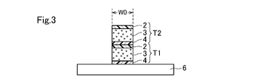
- the same thermal transfer sheet 10 or a different thermal transfer sheet 10 is superposed on the transferred body 6 to which the transfer layer T1 is transferred, and the thermal transfer sheet 10 is heated from the back layer 5 side in the same pattern.
- the second transfer layer T (T2) is transferred onto the first transfer layer T1 to form a laminated body in which the transfer layers T1 and T2 are laminated.
- an image (not shown) is formed on the transferred body 6 provided with the laminated body of the transfer layers T1 and T2.
- the image forming method is not particularly limited, and a sublimation transfer method, a melt transfer method, an inkjet method, or the like can be used.
- the sublimation transfer method and the inkjet method it is preferable to transfer the receiving layer onto the transfer target 6 so as to cover the transfer layers T1 and T2, and then transfer the coloring material to form an image.
- the protective layer may be transferred after image formation.
- an intermediate transfer medium may be used to transfer the layer on which the image is formed onto the transferred body 6 provided with the laminated body.
- the transferred body 6 is heated using a heating device such as a heat roller, an oven, or a thermal head.
- a heating device such as a heat roller, an oven, or a thermal head.
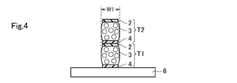
- the foamed particles in the foamed layer 3 of the transfer layers T1 and T2 expand. Due to the expansion of the foamed particles, the foamed layer 3 expands not only in the vertical direction (height direction) but also in the horizontal direction.
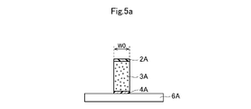
- FIGS. 5a and 5b show a method of manufacturing a printed matter according to a comparative example.
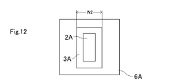
- a transfer layer having an adhesive layer 4A, a foam layer 3A, and a release layer 2A laminated on the transferred body 6A is transferred in a line pattern having a line width W0.
- the thickness of the foam layer 3A is about twice the thickness of the foam layer 3 described above.
- the foamed particles in the foamed layer 3A expand as shown in FIGS. 5b and 12. Due to the expansion of the foamed particles, the foamed layer 3A also expands in the horizontal direction.
- the foamed layer 3A has a larger thickness (volume) per layer than the above-mentioned foamed layer 3, and the amount of expansion in the horizontal direction is particularly large in the central portion in the thickness direction.
- the line width W2 after expansion is larger than the line width W1 in FIGS. 4 and 11, and it is difficult to express a fine uneven pattern.
- the transfer layer T is transferred twice, and the two foam layers 3 are separated by a resin layer (release layer 2 and / or adhesive layer 4) having a high glass transition temperature, and the foam layer is per layer.
- a resin layer release layer 2 and / or adhesive layer 4 having a high glass transition temperature
- the foam layer is per layer.
- FIG. 6 shows a configuration in which the transfer layer T is transferred three times and the three transfer layers T1 to T3 are laminated.
- the transfer of the transfer layer T and the image formation may be performed by the same printer or may be performed by different printers.
- the thermal transfer sheet for transferring the transfer layer T and the thermal transfer sheet for transferring the coloring material may be integrated or may be separate.
- Transfer layers having different thicknesses of the foamed particle-containing layers may be provided in a surface-sequential manner on one thermal transfer sheet.
- a first thermal transfer sheet for transferring the transfer layer T for example, a first thermal transfer sheet for transferring the transfer layer T, a second thermal transfer sheet for transferring the coloring material, and a third thermal transfer sheet for transferring the receiving layer are prepared. ..
- the transfer layer T is provided on the first base material.
- the second thermal transfer sheet is provided with a coloring material layer on the second base material.
- the third thermal transfer sheet is provided with a receiving layer on the third base material.
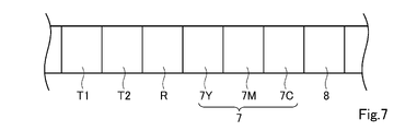
- FIG. 7 is a plan view of the thermal transfer sheet when the thermal transfer sheet for transferring the transfer layer T and the thermal transfer sheet for transferring the coloring material are integrated (a single ribbon). ..
- the thermal transfer sheet has transfer layers T1 and T2, a transfer type receiving layer R, a coloring material layer 7, and a protective layer 8 provided on one surface of the base material in a surface-sequential manner.
- the color material layer 7 includes a yellow color material layer 7Y containing a yellow color material, a magenta color material layer 7M containing a magenta color material, and a cyan color material layer containing a cyan color material, which are sequentially provided on the surface.
- Has 7C The coloring material contained in the yellow color material layer 7Y, the magenta color material layer 7M, and the cyan color material layer 7Y is, for example, a sublimation dye.
- the transfer layers T1 and T2 are heated in the same pattern in order, and the transfer layers T1 and T2 are transferred and laminated on the transferred body. Subsequently, the transcription type receiving layer R is transferred onto the transferred body. Next, the yellow color material layer 7Y, the magenta color material layer 7M, and the cyan color material layer 7Y are transferred in order to form an image on the receiving layer R on the transfer target. Then, the protective layer 8 is heated to transfer the protective layer 8 onto the receiving layer R on which the image is formed.
- the transfer type receiving layer R can be omitted.
- the transfer layer T (foam layer 3) is laminated and the thickness (volume) of the foam layer 3 per layer is reduced to suppress the expansion amount in the horizontal direction
- the transfer layer T may be transferred by a dot pattern (halftone dots) instead of a solid pattern to suppress the width of the foam layer 3 in the horizontal direction.
- W0 be the distance between the transfer layers T at both ends.
- the foamed particles in the foamed layer 3 expand due to the heat treatment, and as shown in FIG. 8b, the foamed layers 3 of the adjacent dot-shaped transfer layers T are bonded to each other to form a line portion having a line width W3.
- the transfer layer T By transferring the transfer layer T in a dot pattern, the volume of each foam layer 3 is reduced, the amount of expansion in the horizontal direction is suppressed, the line width W3 is slightly larger than W0, and a high-definition uneven pattern is formed. Can be expressed.
- the transfer layers T (T1, T2) may be transferred so as to have a dot pattern and two layers are laminated.
- the heat treatment as shown in FIG. 9b, the foam layers 3 of the adjacent dot-shaped transfer layers T1 are bonded to each other, and the foam layers 3 of the transfer layer T2 are bonded to each other.
- a higher-definition uneven pattern can be expressed.
- the positions of the dot pattern of the first transfer layer T1 and the dot pattern of the second transfer layer T2 may be shifted, or the size (width) may be changed.
- the foamed particles are expanded after the image is formed, but the image may be formed after the expanded particles are expanded.
- the transfer layers T1 and T2 may be transferred onto the transferred body 6 (receptive layer) to form a laminate.
- a release layer may be provided between 1 and the transfer layer T. That is, the release layer, the release layer, the foam layer, and the adhesive layer may be laminated in this order on one surface of the base material 1 of the thermal transfer sheet 10.
- the release layer may be omitted from the transfer layer T, and the release layer, the foam layer, and the adhesive layer may be laminated in this order on one surface of the base material 1 of the thermal transfer sheet 10. After the transfer layer T is transferred onto the transfer target 6, the release layer remains on the base material 1.
- the base material 1 of the thermal transfer sheet 10 is not limited in any way, and conventionally known ones in the field of thermal transfer sheets can be appropriately selected and used. Examples include polyester, polyphenylene sulfide, polyether ketone, polyether sulfone, polypropylene, polycarbonate, cellulose acetate, polyethylene derivatives, polyvinyl chloride, polyvinylidene chloride, polystyrene, polyamide, polyimide, polymethylpentene or ionomer, etc. Examples include stretched or unstretched films of plastic.
- the polyester preferably has high heat resistance, and examples thereof include polyethylene terephthalate, polyethylene naphthalate, and polybutylene terephthalate. Further, a composite film in which two or more kinds of these materials are laminated can also be used.
- the thickness of the base material 1 is not particularly limited, but is preferably in the range of 2 ⁇ m or more and 10 ⁇ m or less.
- the release layer 2 is provided at a position closest to the base material 1 of the transfer layer T.
- the binder resin constituting the release layer include cellulose derivatives such as ethyl cellulose, nitrocellulose and cellulose acetate, acrylic resins such as polymethylmethacrylate, ethylpolymethacrylate and butylpolyacrylate, polyvinyl chloride and vinyl chloride.
- Thermoplastic resins such as vinyl acetate copolymers and vinyl resins such as polyvinyl butyral, saturated or unsaturated polyesters, polyurethane resins, thermosetting epoxy-amino copolymers, and thermosetting alkyd-amino copolymers.
- thermosetting resins silicone waxes, silicone resins, silicone-modified resins, fluororesins, fluorine-modified resins, polyvinyl alcohols, and the like, which are exemplified by (thermosetting aminoalkyd resins).
- the glass transition temperature (Tg) of the first resin of the release layer is preferably higher than the glass transition temperature of the first binder resin of the foam layer, which will be described later.
- Tg is a value obtained by differential scanning calorimetry (DSC) in accordance with JIS K7121.
- the foamed layer 3 contains foamed particles and a binder resin.
- the foamed particles are heat-expandable microspheres composed of an outer shell (shell) made of a thermoplastic resin and a foaming agent (core) contained therein.
- the foamed particles have a core-shell structure and exhibit thermal expansion properties (the property that the entire microspheres expand by heating) as the whole microspheres.
- the thermoplastic resin is a polymer of polymerizable components.
- the polymerizable component means a monomer having at least one polymerizable group in the molecule, and is a component that becomes a thermoplastic resin that forms an outer shell of foamed particles by polymerization.
- the polymerizable component includes a non-crosslinkable monomer having one reactive carbon-carbon double bond (hereinafter, simply referred to as a non-crosslinkable monomer), and two or more reactive carbon-carbon double bonds. Examples thereof include crosslinkable monomers having (hereinafter, simply referred to as crosslinkable monomers).
- the crosslinkable monomer allows the bridging structure to be introduced into the polymer.
- the reactive carbon-carbon double bond here means a carbon-carbon double bond exhibiting radical reactivity, and is not a carbon-carbon double bond in an aromatic ring such as a benzene ring or a naphthalene ring, but a vinyl.
- Examples thereof include carbon-carbon double bonds contained in a group, a (meth) acryloyl group, an allyl group, a vinylene group and the like.
- the (meth) acryloyl group shall mean an acryloyl group or a methacryloyl group.
- the foaming agent is a component that vaporizes when heated.
- the foaming agent is not particularly limited, but for example, propane, (iso) butane, (iso) pentane, (iso) hexane, (iso) heptane, (iso) octane, (iso) nonane, (iso) decane, ( Hydrocarbons having 3 to 13 carbon atoms such as iso) undecane, (iso) dodecane, and (iso) tridecane, hydrocarbons having more than 13 carbon atoms and 20 or less carbon atoms such as (iso) hexadecane and (iso) eikosan, pseudocumene, petroleum ether , Initial distilling point 150 ° C or higher and 260 ° C or lower and / or distillation range 70 ° C or higher and 360 ° C or lower, hydrocarbons such as petroleum distillates such as normal paraffin and isoparaffin, methyl chloride,
- Hydrocarbon halides having 1 to 12 carbon atoms fluorine-containing compounds such as hydrofluoroether, alkyl groups having 1 to 5 carbon atoms such as tetramethylsilane, trimethylethylsilane, trimethylisopropylsilane, and trimethyl-n-propylsilane.
- fluorine-containing compounds such as hydrofluoroether
- alkyl groups having 1 to 5 carbon atoms such as tetramethylsilane, trimethylethylsilane, trimethylisopropylsilane, and trimethyl-n-propylsilane.
- Examples thereof include silanes having silanes, azodicarboxylic amides, N, N'-dinitrosopentamethylenetetramine, 4,4'-oxybis (benzenesulfonylhydrazide) and other compounds that generate gas by thermal decomposition by heating.
- the foaming agent may be composed of one kind of compound or a mixture of two or more kinds of compounds.
- the foaming agent may be linear, branched or alicyclic, and is preferably an aliphatic one.
- the encapsulation rate of the foaming agent of the foamed particles is defined as a percentage of the weight of the enclosed foaming agent with respect to the weight of the foamed particles.
- the encapsulation rate of the foaming agent is not particularly limited, but is preferably 2% by weight or more and 50% by weight or less, and more preferably 10% by weight or more and 20% by weight or less with respect to the weight of the foamed particles.
- the expansion start temperature of the foamed particles is not particularly limited, but is preferably 70 ° C. or higher.
- the average particle size (D50) of the foamed particles is 5 ⁇ m or more and 30 ⁇ m or less.
- the average particle size (D50) can be measured by laser diffraction / scattering particle size distribution measurement.
- first binder resin contained in the foam layer examples include cellulose resin, vinyl resin, acrylic resin, polyester and the like, and polyester is particularly preferable.
- the glass transition temperature of the first binder resin is preferably lower than the glass transition temperature of the first resin of the release layer described above.
- the first binder resin contained in the foamed layer preferably has a high glass transition temperature, and preferably has a low ratio of the foaming agent in the foamed layer.
- the glass transition temperature of the first binder resin is preferably 40 ° C. or higher and 80 ° C. or lower, and the ratio of the foaming agent in the foam layer is preferably about 2: 8 to 4: 6.
- the first binder resin contained in the foamed layer preferably has a low glass transition temperature.
- the glass transition temperature of the first binder resin is preferably ⁇ 20 ° C. or higher and 20 ° C. or lower.
- the first binder resin is determined according to the shape required for the uneven pattern.
- the thickness of the foamed layer before the expanded particles expand is preferably 5 ⁇ m or more and 50 ⁇ m or less.
- the thickness of the foamed layer (the total thickness of the plurality of foamed layers) after the expanded particles are expanded is preferably 250 ⁇ m or more and 600 ⁇ m or less.
- An adhesive layer 4 is provided on the foam layer 3 in order to improve the adhesion between the transfer material and the transfer layer T.
- the material of the adhesive layer include cellulose derivatives such as ethyl cellulose and cellulose vinegar butyrate, styrene copolymers such as polystyrene and poly ⁇ -methyl styrene, acrylic resins such as polymethyl methacrylate, polyethyl methacrylate and polyethyl acrylate, and poly.
- examples thereof include vinyl chloride, polyvinyl acetate, vinyl chloride-vinyl acetate copolymer, vinyl resin such as polyvinyl butyral, polyester, nylon resin, epoxy resin and polyurethane. It is preferable that the glass transition temperature of the first resin of the adhesive layer is higher than the glass transition temperature of the first binder resin of the foamed layer.
- the material of the back layer 5 is not limited, and for example, a cellulose resin such as cellulose acetate butyrate or cellulose acetate propionate, a vinyl resin such as polyvinyl butyral or polyvinyl acetal, polymethyl methacrylate, ethyl polyacrylate, polyacrylamide, etc.
- a cellulose resin such as cellulose acetate butyrate or cellulose acetate propionate
- a vinyl resin such as polyvinyl butyral or polyvinyl acetal
- polymethyl methacrylate ethyl polyacrylate
- polyacrylamide etc.
- acrylic resins such as acrylonitrile-styrene copolymers
- natural or synthetic resins such as polyamide resins, polyamideimides, polyesters, polyurethanes, silicone-modified or fluorine-modified urethanes.
- the back layer may contain one of these resins alone or may contain two or more of these resins.
- the transfer-type receiving layer R shown in FIG. 7 has a receiving layer and an adhesive layer that are laminated in order from the base material side.
- the material of the receiving layer is not particularly limited, but it is preferable to use a binder resin in which the sublimation dye contained in the coloring material layer is easily dyed.
- binder resins include polyolefins such as polypropylene, halogenated resins such as polyvinyl chloride and vinylidene chloride, vinyl resins such as polyvinyl acetate and polyacrylic ester, polyesters such as polyethylene terephthalate and polybutylene terephthalate, and polystyrene. Examples thereof include polyamide, ionomer, and cellulose resin.
- the receiving layer may contain one of these binder resins alone, or may contain two or more of these binder resins.
- the thickness of the receiving layer is generally 1.0 ⁇ m or more and 10 ⁇ m or less, preferably 1.0 ⁇ m or more and 5.0 ⁇ m or less.
- the binder resin constituting the protective layer 8 examples include polyester, polyester urethane resin, polycarbonate, acrylic resin, epoxy resin, acrylic urethane resin, a resin obtained by silicone-modifying each of these resins, and a mixture of these resins. Can be mentioned.
- the protective layer may contain an ultraviolet absorbing resin or an active photocurable resin.
- the active light means a light that chemically acts on the active photocurable resin to promote polymerization, and specifically, visible light, ultraviolet rays, X-rays, electron beams, ⁇ rays, and ⁇ rays. It means line, ⁇ -ray, etc.
- a release layer may be provided between the base material and the protective layer in order to improve the transferability of the protective layer.
- thermo transfer sheet 1 A PET film having a thickness of 5 ⁇ m was used as a base material, and a coating liquid for a back layer having the following composition was applied to one surface of the base material and dried to form a back layer having a thickness of 1 ⁇ m. Further, a release layer having the following composition was applied to the other surface of the base material and dried to form a release layer having a thickness of 0.5 ⁇ m. Next, a foaming layer coating liquid 1 having the following composition was applied onto the peeling layer and dried to form a foaming layer having a thickness of 30 ⁇ m. Next, an adhesive layer coating liquid 1 having the following composition is applied onto the foam layer and dried to form an adhesive layer having a thickness of 2.5 ⁇ m. A thermal transfer sheet 1 in which the adhesive layers were laminated in this order was obtained.
- ⁇ Coating liquid for foam layer 1 5 parts by mass of foamed particles A (Matsumoto Microsphere (registered trademark) HF30D, Matsumoto Yushi Pharmaceutical Co., Ltd., foaming temperature: 115 ° C., average particle size: 14 ⁇ m) 5 parts by mass of polyester (Byronal (registered trademark) MD1930, Toyobo Co., Ltd., glass transition temperature: -10 ° C) ⁇ 23 parts by mass of water
- ⁇ Coating liquid for adhesive layer 1 5 parts by mass of polyester (Byronal (registered trademark) MD1930, Toyobo Co., Ltd., glass transition temperature: -10 ° C) ⁇ 15 parts by mass of water
- thermal transfer sheet 2 was produced in the same manner as the thermal transfer sheet 1 except that a foam layer having a thickness of 40 ⁇ m was formed by applying the foaming layer coating liquid 1 having the above composition on the release layer and drying it. did.
- thermal transfer sheet 3 is produced in the same manner as the thermal transfer sheet 1 except that a foam layer having a thickness of 20 ⁇ m is formed by applying the foaming layer coating liquid 1 having the above composition on the release layer and drying it. did.
- thermal transfer sheet 4 is the same as the thermal transfer sheet 1 except that an adhesive layer having a thickness of 2.5 ⁇ m is formed by applying the adhesive layer coating liquid 2 having the following composition on the foam layer and drying it. Was produced.
- thermal transfer sheet 5 is produced in the same manner as the thermal transfer sheet 4 except that a foam layer having a thickness of 30 ⁇ m is formed by applying the foaming layer coating liquid 2 having the following composition on the release layer and drying it. did.
- ⁇ Coating liquid for foam layer 2 > 5 parts by mass of foamed particles B (Matsumoto Microsphere (registered trademark) FN80GSD, Matsumoto Yushi Pharmaceutical Co., Ltd., foaming temperature 115 ° C., average particle size: 13 ⁇ m) ⁇ 5 parts by mass of polyester (Byronal (registered trademark) MD1930, Toyobo Co., Ltd.) ⁇ 23 parts by mass of water
- thermal transfer sheet 6 is produced in the same manner as the thermal transfer sheet 4 except that a foam layer having a thickness of 30 ⁇ m is formed by applying a foam layer coating liquid 3 having the following composition on the release layer and drying the layer. did.
- ⁇ Coating liquid for foam layer 3 5 parts by mass of foamed particles C (Matsumoto Microsphere (registered trademark) HF36D, Matsumoto Yushi Pharmaceutical Co., Ltd., foaming temperature 115 ° C., average particle size: 13 ⁇ m) ⁇ 5 parts by mass of polyester (Byronal (registered trademark) MD1930, Toyobo Co., Ltd.) ⁇ 23 parts by mass of water
- thermal transfer sheet 7 was produced in the same manner as the thermal transfer sheet 4 except that a foam layer having a thickness of 30 ⁇ m was formed by applying a foam layer coating liquid 4 having the following composition on the release layer and drying the layer. did.
- ⁇ Coating liquid for foam layer 4 5 parts by mass of foamed particles D (Matsumoto Microsphere (registered trademark) HF48D, Matsumoto Yushi Pharmaceutical Co., Ltd., foaming temperature 130 ° C., average particle size: 12 ⁇ m) ⁇ 5 parts by mass of polyester (Byronal (registered trademark) MD1930, Toyobo Co., Ltd.) ⁇ 23 parts by mass of water
- thermal transfer sheet 8 is produced in the same manner as the thermal transfer sheet 4 except that a foam layer having a thickness of 30 ⁇ m is formed by applying a foam layer coating liquid 5 having the following composition on the release layer and drying the layer. did.
- ⁇ Coating liquid for foam layer 5 Effervescent particles E 5 parts by mass (Matsumoto Microsphere (registered trademark) F36LVD, Matsumoto Yushi Pharmaceutical Co., Ltd., foaming temperature 115 ° C., average particle size: 16 ⁇ m) ⁇ 5 parts by mass of polyester (Byronal (registered trademark) MD1930, Toyobo Co., Ltd.) ⁇ 23 parts by mass of water
- thermal transfer sheet 9 is the same as the thermal transfer sheet 1 except that an adhesive layer having a thickness of 2.5 ⁇ m is formed by applying the adhesive layer coating liquid 3 having the following composition on the foam layer and drying it. Was produced.
- thermo transfer sheet 10 is produced in the same manner as the thermal transfer sheet 1 except that a foam layer having a thickness of 60 ⁇ m is formed by applying the foaming layer coating liquid 1 having the above composition on the release layer and drying it. did.
- a coated paper having a thickness of 225 ⁇ m was prepared as a transfer material.
- the adhesive layers of the thermal transfer sheets 1 to 9 produced above and the transferred body are opposed to each other, and a transfer layer composed of a release layer, a foam layer, and an adhesive layer is laminated on the transferred body a plurality of times using the following thermal transfer printer. And transferred.
- the transfer pattern of the transfer layer was a square of 10 mm ⁇ 10 mm (the size in the x direction and the y direction was 10 mm) in a plan view.
- Thermal head F3589 (manufactured by Toshiba Hokuto Electronics Corporation) -Average resistance value of heating element: 5015 ⁇ -Printing voltage: 15V (18V only in Comparative Example 2) -Main scanning direction resolution: 300 dpi (dot per inch) -Secondary scanning direction resolution: 300 dpi -Line speed: 6.0 msec. / Line -Printing start temperature: 35 ° C -Pulse duty ratio: 85% ⁇ Gradation value: 255/255 (maximum energy gradation)
- the adhesive layer coating liquid 1 having the above composition is applied onto the foam layer and dried to form an adhesive layer having a thickness of 2 ⁇ m, and the back layer, the base material, the release layer, the foam layer, and the adhesive layer are formed. Obtained a thermal transfer sheet 11 laminated in this order.
- thermo transfer sheet 12 A thermal transfer sheet 11 except that a foam layer having a thickness of 15 ⁇ m was formed by applying a foam layer coating liquid 7 having the following composition instead of the foam layer coating liquid 6 and drying the release layer.
- the thermal transfer sheet 12 was produced in the same manner as in the above.
- thermo transfer sheet 13 (Preparation of Thermal Transfer Sheet 13) A thermal transfer sheet 11 except that a foam layer having a thickness of 15 ⁇ m was formed by applying a foam layer coating liquid 8 having the following composition instead of the foam layer coating liquid 6 and drying the release layer.
- the thermal transfer sheet 13 was produced in the same manner as in the above.
- thermo transfer sheet 14 (Preparation of thermal transfer sheet 14) A thermal transfer sheet 11 except that a foam layer having a thickness of 15 ⁇ m was formed by applying a foam layer coating liquid 9 having the following composition instead of the foam layer coating liquid 6 and drying the release layer. The thermal transfer sheet 14 was produced in the same manner as in the above.
- a PET film having a thickness of 100 ⁇ m was prepared as a transfer body.
- the adhesive layers of the thermal transfer sheets 11 to 14 produced above and the transferred body are opposed to each other, and the transfer layer composed of the release layer, the foam layer, and the adhesive layer is laminated twice on the transferred body by using the thermal transfer printer. And transferred.
- the transfer pattern of the transfer layer was a square of 10 mm ⁇ 10 mm (the size in the x direction and the y direction was 10 mm) in a plan view.
- An image is formed on the transferred body to which the transfer layer is transferred using heat-meltable ink, and the image is heated with a heat roll (Lamipacker Meister6 LPD3226, manufactured by Fujipla) to expand the foamed particles of the foamed layer, and Reference Example 1 to 1 to The printed matter of 4 was prepared.
- the heat roll was set at a set temperature of 150 ° C. and a speed of 0.4 m / min.
- Table 2 shows the types of thermal transfer sheets used to prepare the printed materials of Reference Examples 1 to 4.
Landscapes
- Physics & Mathematics (AREA)
- Optics & Photonics (AREA)
- Thermal Transfer Or Thermal Recording In General (AREA)
- Laminated Bodies (AREA)
Abstract
Description
熱転写シート10の基材1についていかなる限定もされることはなく、熱転写シートの分野で従来公知のものを適宜選択して用いることができる。一例としては、ポリエステル、ポリフェニレンサルファイド、ポリエーテルケトン、ポリエーテルサルホン、ポリプロピレン、ポリカーボネート、酢酸セルロース、ポリエチレン誘導体、ポリ塩化ビニル、ポリ塩化ビニリデン、ポリスチレン、ポリアミド、ポリイミド、ポリメチルペンテンまたはアイオノマー、等のプラスチックの延伸または未延伸フィルムが挙げられる。ポリエステルとしては、耐熱性が高いものが好ましく、例えば、ポリエチレンテレフタレート、ポリエチレンナフタレート、ポリブチレンテレフタレート、等が挙げられる。また、これらの材料を2種以上積層した複合フィルムも使用できる。基材1の厚さについて特に限定はないが、2μm以上10μm以下の範囲が好ましい。
転写層Tの転写性を向上させるべく、転写層Tの最も基材1に近い位置に剥離層2が設けられる。剥離層を構成するバインダー樹脂としては、例えば、エチルセルロース、ニトロセルロース、酢酸セルロース等のセルロース誘導体、ポリメタクリル酸メチル、ポリメタクリル酸エチル、ポリアクリル酸ブチル等のアクリル樹脂、ポリ塩化ビニル、塩化ビニル-酢酸ビニル共重合体、ポリビニルブチラール等のビニル樹脂等に例示される熱可塑性樹脂、飽和又は不飽和ポリエステル、ポリウレタン樹脂、熱硬化性エポキシ-アミノ共重合体、及び熱硬化性アルキッド-アミノ共重合体(熱硬化性アミノアルキド樹脂)等に例示される熱硬化性樹脂、シリコーンワックス、シリコーン樹脂、シリコーン変性樹脂、フッ素樹脂、フッ素変性樹脂、ポリビニルアルコール等を挙げることができる。
発泡層3は、発泡粒子及びバインダー樹脂を含有している。発泡粒子は、熱可塑性樹脂からなる外殻(シェル)と、それに内包される発泡剤(コア)とから構成される熱膨張性微小球である。発泡粒子はコア-シェル構造をとっており、微小球全体として熱膨張性(微小球全体が加熱により膨らむ性質)を示す。熱可塑性樹脂は、重合性成分の重合体である。
被転写体と転写層Tとの密着性を向上させるべく、発泡層3上に接着層4が設けられている。接着層の材料としては、例えば、エチルセルロース、酢酪酸セルロース等のセルロース誘導体、ポリスチレン、ポリα-メチルスチレン等のスチレン共重合体、ポリメチルメタクリレート、ポリエチルメタクリレート、ポリエチルアクリレート等のアクリル樹脂、ポリ塩化ビニル、ポリ酢酸ビニル、塩化ビニル-酢酸ビニル共重合体、ポリビニルブチラール等のビニル樹脂、ポリエステル、ナイロン樹脂、エポキシ樹脂及びポリウレタン等を挙げることができる。接着層の第1樹脂のガラス転移温度が、上記発泡層の第1バインダー樹脂のガラス転移温度より高いことが好ましい。
背面層5の材料について限定はなく、例えば、セルロースアセテートブチレート、セルロースアセテートプロピオネート等のセルロース樹脂、ポリビニルブチラール、ポリビニルアセタール等のビニル樹脂、ポリメタクリル酸メチル、ポリアクリル酸エチル、ポリアクリルアミド、アクリロニトリル-スチレン共重合体等のアクリル樹脂、ポリアミド樹脂、ポリアミドイミド、ポリエステル、ポリウレタン、シリコーン変性又はフッ素変性ウレタン等の天然又は合成樹脂等を挙げることができる。背面層は、これらの樹脂の1種を単独で含有してもよく、2種以上を含有してもよい。
図7に示す転写型受容層Rは、基材側から順に積層された受容層及び接着層を有する。受容層の材料について特に限定はないが、色材層に含有される昇華性染料が染着し易いバインダー樹脂を用いることが好ましい。このようなバインダー樹脂としては、ポリプロピレン等のポリオレフィン、ポリ塩化ビニル、ポリ塩化ビニリデン等のハロゲン化樹脂、ポリ酢酸ビニル、ポリアクリルエステル等のビニル樹脂、ポリエチレンテレフタレート、ポリブチレンテレフタレート等のポリエステル、ポリスチレン、ポリアミド、アイオノマー、セルロース樹脂等を挙げることができる。受容層は、これらのバインダー樹脂の1種を単独で含有してもよく、2種以上を含有してもよい。
保護層8を構成するバインダー樹脂としては、例えば、ポリエステル、ポリエステルウレタン樹脂、ポリカーボネート、アクリル樹脂、エポキシ樹脂、アクリルウレタン樹脂、これらの各樹脂をシリコーン変性させた樹脂、これらの各樹脂の混合物等を挙げることができる。保護層は、紫外線吸収性樹脂や活性光線硬化性樹脂を含有してもよい。なお、活性光線とは、活性光線硬化性樹脂に対して化学的に作用させて重合を促進せしめる光線を意味し、具体的には、可視光線、紫外線、X線、電子線、α線、β線、γ線等を意味する。保護層の転写性を向上させるべく、基材と保護層との間に剥離層を設けてもよい。
(熱転写シート1の作製)
基材として、厚さ5μmのPETフィルムを用い、該基材の一方の面に、下記組成の背面層用塗工液を塗布し、乾燥させることにより、厚さ1μmの背面層を形成した。また、基材の他方の面に、下記組成の剥離層用塗工液を塗布し、乾燥させることにより、厚さ0.5μmの剥離層を形成した。次いで、剥離層上に、下記組成の発泡層用塗工液1を塗布し、乾燥させることにより、厚さ30μmの発泡層を形成した。次いで、発泡層上に、下記組成の接着層用塗工液1を塗布し、乾燥させることにより、厚さ2.5μmの接着層を形成し、背面層、基材、剥離層、発泡層、接着層がこの順で積層された熱転写シート1を得た。
・アクリル樹脂 19質量部
(ダイヤナール(登録商標) BR-87、三菱ケミカル(株)、ガラス転移温度:106℃)
・ポリエステル 1質量部
(バイロン(登録商標)200、東洋紡(株))
・メチルエチルケトン 40質量部
・トルエン 40質量部
・ポリビニルアセタール 36質量部
(エスレック(登録商標)KS-1、積水化学工業(株))
・イソシアネート化合物 25質量部
(バーノック(登録商標)D750、DIC(株))
・シリコーン樹脂微粒子 1質量部
(トスパール(登録商標)240、モメンティブ・パフォーマンス・マテリアルズ・ジャパン合同会社)
・ステアリルリン酸亜鉛 10質量部
(LBT1830精製、堺化学工業(株))
・ステアリン酸亜鉛 10質量部
(SZ-PF、堺化学工業(株))
・ポリエチレンワックス 3質量部
(ポリワックス3000、東洋アドレ(株))
・エトキシ化アルコール変性ワックス 7質量部
(ユニトックス750、東洋アドレ(株))
・メチルエチルケトン 200質量部
・トルエン 100質量部
・発泡粒子A 5質量部
(マツモトマイクロスフェアー(登録商標)HF30D、松本油脂製薬(株)、発泡温度:115℃、平均粒子径:14μm)
・ポリエステル 5質量部
(バイロナール(登録商標)MD1930、東洋紡(株)、ガラス転移温度:-10℃)
・水 23質量部
・ポリエステル 5質量部
(バイロナール(登録商標)MD1930、東洋紡(株)、ガラス転移温度:-10℃)
・水 15質量部
剥離層上に、上記組成の発泡層用塗工液1を塗布し、乾燥させることにより、厚さ40μmの発泡層を形成した以外は、全て熱転写シート1と同様にして、熱転写シート2を作製した。
剥離層上に、上記組成の発泡層用塗工液1を塗布し、乾燥させることにより、厚さ20μmの発泡層を形成した以外は、全て熱転写シート1と同様にして、熱転写シート3を作製した。
発泡層上に、下記組成の接着層用塗工液2を塗布し、乾燥させることにより、厚さ2.5μmの接着層を形成した以外は、全て熱転写シート1と同様にして、熱転写シート4を作製した。
・変性ポリオレフィン 4質量部
(アローベース(登録商標)SA1200、ユニチカ(株)、ガラス転移温度:-30℃)
・IPA 6質量部
・水 6質量部
剥離層上に、下記組成の発泡層用塗工液2を塗布し、乾燥させることにより、厚さ30μmの発泡層を形成した以外は、全て熱転写シート4と同様にして、熱転写シート5を作製した。
・発泡粒子B 5質量部
(マツモトマイクロスフェアー(登録商標)FN80GSD、松本油脂製薬(株)、発泡温度115℃、平均粒子径:13μm)
・ポリエステル 5質量部
(バイロナール(登録商標)MD1930、東洋紡(株))
・水 23質量部
剥離層上に、下記組成の発泡層用塗工液3を塗布し、乾燥させることにより、厚さ30μmの発泡層を形成した以外は、全て熱転写シート4と同様にして、熱転写シート6を作製した。
・発泡粒子C 5質量部
(マツモトマイクロスフェアー(登録商標)HF36D、松本油脂製薬(株)、発泡温度115℃、平均粒子径:13μm)
・ポリエステル 5質量部
(バイロナール(登録商標)MD1930、東洋紡(株))
・水 23質量部
剥離層上に、下記組成の発泡層用塗工液4を塗布し、乾燥させることにより、厚さ30μmの発泡層を形成した以外は、全て熱転写シート4と同様にして、熱転写シート7を作製した。
・発泡粒子D 5質量部
(マツモトマイクロスフェアー(登録商標)HF48D、松本油脂製薬(株)、発泡温度130℃、平均粒子径:12μm)
・ポリエステル 5質量部
(バイロナール(登録商標)MD1930、東洋紡(株))
・水 23質量部
剥離層上に、下記組成の発泡層用塗工液5を塗布し、乾燥させることにより、厚さ30μmの発泡層を形成した以外は、全て熱転写シート4と同様にして、熱転写シート8を作製した。
・発泡粒子E 5質量部
(マツモトマイクロスフェアー(登録商標)F36LVD、松本油脂製薬(株)、発泡温度115℃、平均粒子径:16μm)
・ポリエステル 5質量部
(バイロナール(登録商標)MD1930、東洋紡(株))
・水 23質量部
発泡層上に、下記組成の接着層用塗工液3を塗布し、乾燥させることにより、厚さ2.5μmの接着層を形成した以外は、全て熱転写シート1と同様にして、熱転写シート9を作製した。
・ポリエステル 5質量部
(エリーテル(登録商標)KA-1237、ユニチカ(株)、ガラス転移温度:71℃)
・水 15質量部
剥離層上に、上記組成の発泡層用塗工液1を塗布し、乾燥させることにより、厚さ60μmの発泡層を形成した以外は、全て熱転写シート1と同様にして、熱転写シート10を作製した。
被転写体として、厚さ225μmのコート紙を準備した。上記で作製した熱転写シート1~9の接着層と被転写体とを対向させ、下記熱転写プリンタを用いて、被転写体上に、剥離層、発泡層、接着層からなる転写層を複数回重ねて転写した。転写層の転写パターンは、平面視で10mm×10mm(x方向及びy方向のサイズが10mm)の正方形とした。
・サーマルヘッド:F3589(東芝ホクト電子(株)製)
・発熱体平均抵抗値:5015Ω
・印画電圧:15V(比較例2のみ18V)
・主走査方向解像度:300dpi(dot per inch)
・副走査方向解像度:300dpi
・ライン速度:6.0msec./line
・印画開始温度:35℃
・パルスDuty比:85%
・諧調値:255/255(最大エネルギー諧調)
熱転写シートから被転写体へ転写した転写層を目視により観察し、下記評価基準に基づいて、転写層の転写性を評価した。評価結果を表1に示す。
〇 転写不良(尾引き、転写しない部分)なし
△ 転写不良が10%未満ある
× 転写不良が10%以上ある
積層された転写層の発泡(膨張)前後の厚みを測定し、発泡後の厚みから発泡前の厚みを減じて発泡量を算出し、下記評価基準に基づいて発泡量を評価した。厚みの測定には、デジタルマイクロメータ(MDC-25MX、(株)ミツトヨ)を使用した。
◎ 400μm以上
○ 250μm以上400μm未満
△ 150μm以上250μm未満
× 150μm未満
発泡後の転写層(発泡層)のx方向及びy方向のサイズを測定し、大きい方のサイズについて、発泡前のサイズを基準とした倍率を算出し、下記評価基準に基づいてパターンの先鋭性を評価した。発泡後の転写層のサイズ測定にはマイクロスコープ(VHX1000、(株)キーエンス)を使用した。
○ 125%未満
△ 125%以上155%未満
× 155%以上

(熱転写シート11の作製)
基材として、厚さ5μmのPETフィルムを用い、該基材の一方の面に、上記組成の背面層用塗工液を塗布し、乾燥させることにより、厚さ1μmの背面層を形成した。また、基材の他方の面に、上記組成の剥離層用塗工液を塗布し、乾燥させることにより、厚さ1μmの剥離層を形成した。次いで、剥離層上に、下記組成の発泡層用塗工液6を塗布し、乾燥させることにより、厚さ15μmの発泡層を形成した。次いで、発泡層上に、上記組成の接着層用塗工液1を塗布し、乾燥させることにより、厚さ2μmの接着層を形成し、背面層、基材、剥離層、発泡層、接着層がこの順で積層された熱転写シート11を得た。
・発泡粒子F 5質量部
(マツモトマイクロスフェアー(登録商標)HF50D、松本油脂製薬(株)、発泡温度:115℃、平均粒子径:14μm)
・ポリエステル 5質量部
(バイロナール(登録商標)MD1930、東洋紡(株)、ガラス転移温度:-10℃)
・水 23質量部
剥離層上に、発泡層用塗工液6に代えて下記組成の発泡層用塗工液7を塗布し、乾燥させることにより、厚さ15μmの発泡層を形成した以外は、全て熱転写シート11と同様にして、熱転写シート12を作製した。
・発泡粒子F 3質量部
(マツモトマイクロスフェアー(登録商標)HF50D、松本油脂製薬(株)、発泡温度:115℃、平均粒子径:14μm)
・ポリエステル 7質量部
(バイロナール(登録商標)MD1930、東洋紡(株)、ガラス転移温度:-10℃)
・水 23質量部
剥離層上に、発泡層用塗工液6に代えて下記組成の発泡層用塗工液8を塗布し、乾燥させることにより、厚さ15μmの発泡層を形成した以外は、全て熱転写シート11と同様にして、熱転写シート13を作製した。
・発泡粒子F 7質量部
(マツモトマイクロスフェアー(登録商標)HF50D、松本油脂製薬(株)、発泡温度:115℃、平均粒子径:14μm)
・ポリエステル 3質量部
(バイロナール(登録商標)MD1930、東洋紡(株)、ガラス転移温度:-10℃)
・水 23質量部
剥離層上に、発泡層用塗工液6に代えて下記組成の発泡層用塗工液9を塗布し、乾燥させることにより、厚さ15μmの発泡層を形成した以外は、全て熱転写シート11と同様にして、熱転写シート14を作製した。
・発泡粒子F 5質量部
(マツモトマイクロスフェアー(登録商標)HF50D、松本油脂製薬(株)、発泡温度:115℃、平均粒子径:14μm)
・ポリエステル 5質量部
(バイロナール(登録商標)MD1200、東洋紡(株)、ガラス転移温度:67℃)
・水 23質量部
被転写体として、厚さ100μmのPETフィルムを準備した。上記で作製した熱転写シート11~14の接着層と被転写体とを対向させ、上記熱転写プリンタを用いて、被転写体上に、剥離層、発泡層、接着層からなる転写層を2回重ねて転写した。転写層の転写パターンは、平面視で10mm×10mm(x方向及びy方向のサイズが10mm)の正方形とした。
発泡層の発泡(膨張)前後の印画物の厚みを測定し、発泡後の印画物の厚みから発泡前の印画物の厚みを減じて発泡量を算出した。また、印画物の厚みから被転写体の厚みを減じて積層された転写層の厚みを求め、発泡後の転写層の厚みを発泡前の転写層の厚みで除して膨張率を算出した。計算結果を表2に示す。なお、印画物の厚みの測定には、デジタルマイクロメータ(MDC-25MX、(株)ミツトヨ)を使用した。
発泡後の転写層(発泡層)のx方向及びy方向のサイズを測定し、大きい方のサイズについて、発泡前のサイズを基準とした倍率を算出した。計算結果を表2に示す。発泡後の転写層のサイズ測定にはマイクロスコープ(VHX1000、(株)キーエンス)を使用した。

本出願は、2021年1月18日付で出願された日本特許出願2021-5867に基づいており、その全体が引用により援用される。
2 剥離層
3 発泡層
4 接着層
5 背面層
6 被転写体
10 熱転写シート
Claims (12)
- 基材と、前記基材の一方の面側に設けられた、発泡粒子を含有する層を有する転写層とを有する熱転写シートを準備する工程と、
前記熱転写シートを加熱し、被転写体上に、前記熱転写シートの前記転写層を所定のパターンで複数回重ねて転写し、複数の前記転写層が積層された積層体を形成する工程と、
を備える印画物の製造方法。 - 前記積層体を加熱して、前記発泡粒子を含有する層を膨張させる工程をさらに備える、請求項1に記載の印画物の製造方法。
- 前記熱転写シートから、前記転写層をドットパターンで転写する、請求項1又は2に記載の印画物の製造方法。
- 前記積層体を加熱して前記発泡粒子を含有する層を膨張させ、隣接するドット状の前記転写層に含まれる発泡粒子を含有する層同士を結合させる、請求項3に記載の印画物の製造方法。
- 前記転写層は、前記基材の一方の面側に順に積層された剥離層、前記発泡粒子を含有する層、及び接着層を有する、請求項1乃至4のいずれかに記載の印画物の製造方法。
- 前記剥離層の第1樹脂のガラス転移温度は、前記発泡層の第1バインダー樹脂のガラス転移温度よりも高い、請求項5に記載の印画物の製造方法。
- 前記接着層の第1樹脂のガラス転移温度は、前記発泡層の第1バインダー樹脂のガラス転移温度よりも高い、請求項5又は6に記載の印画物の製造方法。
- 被転写体と、
前記被転写体上に設けられ、転写層が複数積層された積層体と、
を備え、
複数の前記転写層は、それぞれ、前記被転写体側から順に積層された接着層、及び発泡粒子を含有する層を有する、印画物。 - 前記複数の転写層は、それぞれ、前記発泡粒子を含有する層からみて前記被転写体とは反対側に剥離層をさらに有する、請求項8に記載の印画物。
- 基材と、
前記基材の一方の面上に面順次に設けられた複数の転写層と、
を備え、
前記複数の転写層は、それぞれ、前記基材の一方の面側から順に積層された発泡粒子を含有する層、及び接着層を有する、熱転写シート。 - 第1基材と、前記第1基材の一方の面側に設けられた、発泡粒子を含有する層を有する転写層とを備える第1熱転写シートを準備する工程と、
第2基材と、前記第2基材の一方の面側に設けられた色材層とを有する第2熱転写シートを準備する工程と、
第3基材と、前記第3基材の一方の面側に設けられた受容層とを有する第3熱転写シートを準備する工程と、
前記第1熱転写シートを加熱し、被転写体上に、前記第1熱転写シートの前記転写層を所定のパターンで複数回重ねて転写し、複数の前記転写層が積層された積層体を形成する工程と、
前記第2熱転写シートを加熱し、前記第3熱転写シートの前記受容層に色材を転写して画像を形成する工程と、
前記第3熱転写シートを加熱し、前記画像が形成された受容層を前記積層体上に転写する工程と、
を備える印画物の製造方法。 - 第1基材と、前記第1基材の一方の面側に設けられた、発泡粒子を含有する層を有する転写層とを備える第1熱転写シートを準備する工程と、
第2基材と、前記第2基材の一方の面側に設けられた色材層とを有する第2熱転写シートを準備する工程と、
第3基材と、前記第3基材の一方の面側に設けられた受容層とを有する第3熱転写シートを準備する工程と、
前記第2熱転写シートを加熱し、前記第3熱転写シートの前記受容層に色材を転写して画像を形成する工程と、
前記第3熱転写シートを加熱し、前記画像が形成された受容層を被転写体上に転写する工程と、
前記第1熱転写シートを加熱し、前記受容層が転写された前記被転写体上に、前記第1熱転写シートの前記転写層を所定のパターンで複数回重ねて転写し、複数の前記転写層が積層された積層体を形成する工程と、
を備える印画物の製造方法。
Priority Applications (4)
| Application Number | Priority Date | Filing Date | Title |
|---|---|---|---|
| US18/258,843 US20240109360A1 (en) | 2021-01-18 | 2022-01-17 | Method for manufacturing printed material, printed material, and thermal transfer sheet |
| CN202280009984.2A CN116802061A (zh) | 2021-01-18 | 2022-01-17 | 印刷物的制造方法、印刷物以及热转印片 |
| JP2022554174A JP7218838B2 (ja) | 2021-01-18 | 2022-01-17 | 印画物の製造方法、印画物及び熱転写シート |
| EP22739525.8A EP4279286A1 (en) | 2021-01-18 | 2022-01-17 | Method for manufacturing printed matter, printed matter, and heat transfer sheet |
Applications Claiming Priority (2)
| Application Number | Priority Date | Filing Date | Title |
|---|---|---|---|
| JP2021005867 | 2021-01-18 | ||
| JP2021-005867 | 2021-01-18 |
Publications (1)
| Publication Number | Publication Date |
|---|---|
| WO2022154120A1 true WO2022154120A1 (ja) | 2022-07-21 |
Family
ID=82448190
Family Applications (1)
| Application Number | Title | Priority Date | Filing Date |
|---|---|---|---|
| PCT/JP2022/001399 WO2022154120A1 (ja) | 2021-01-18 | 2022-01-17 | 印画物の製造方法、印画物及び熱転写シート |
Country Status (5)
| Country | Link |
|---|---|
| US (1) | US20240109360A1 (ja) |
| EP (1) | EP4279286A1 (ja) |
| JP (1) | JP7218838B2 (ja) |
| CN (1) | CN116802061A (ja) |
| WO (1) | WO2022154120A1 (ja) |
Citations (6)
| Publication number | Priority date | Publication date | Assignee | Title |
|---|---|---|---|---|
| JPH08282135A (ja) * | 1995-04-20 | 1996-10-29 | Toppan Printing Co Ltd | 昇華転写記録用受像体 |
| JPH09156226A (ja) * | 1995-12-12 | 1997-06-17 | Dainippon Printing Co Ltd | 盛り上げ画像形成用熱転写シートおよびそれを用いた画像形成方法 |
| JPH10138639A (ja) * | 1996-11-12 | 1998-05-26 | Dainippon Printing Co Ltd | 盛り上げ画像形成装置、および盛り上げ画像形成方法 |
| JPH10151870A (ja) * | 1996-11-22 | 1998-06-09 | Dainippon Printing Co Ltd | 盛り上げ画像形成用熱転写シート、盛り上げ画像形成方法および盛り上げ画像形成物 |
| JP2017196739A (ja) * | 2016-04-25 | 2017-11-02 | 凸版印刷株式会社 | 画像形成体、画像形成用媒体及び画像形成体の製造方法 |
| JP2021005867A (ja) | 2019-06-25 | 2021-01-14 | 日本放送協会 | 符号化装置、復号装置、及びプログラム |
Family Cites Families (3)
| Publication number | Priority date | Publication date | Assignee | Title |
|---|---|---|---|---|
| JPH0952450A (ja) * | 1995-08-10 | 1997-02-25 | Dainippon Printing Co Ltd | 盛り上げ画像形成用熱転写シートおよびそれを用いた画像形成方法 |
| JP2007237652A (ja) | 2006-03-10 | 2007-09-20 | Fujifilm Corp | 感熱転写受像シート |
| JP2020019268A (ja) | 2018-08-03 | 2020-02-06 | カシオ計算機株式会社 | 熱膨張性シート |
-
2022
- 2022-01-17 EP EP22739525.8A patent/EP4279286A1/en active Pending
- 2022-01-17 US US18/258,843 patent/US20240109360A1/en active Pending
- 2022-01-17 CN CN202280009984.2A patent/CN116802061A/zh active Pending
- 2022-01-17 JP JP2022554174A patent/JP7218838B2/ja active Active
- 2022-01-17 WO PCT/JP2022/001399 patent/WO2022154120A1/ja active Application Filing
Patent Citations (6)
| Publication number | Priority date | Publication date | Assignee | Title |
|---|---|---|---|---|
| JPH08282135A (ja) * | 1995-04-20 | 1996-10-29 | Toppan Printing Co Ltd | 昇華転写記録用受像体 |
| JPH09156226A (ja) * | 1995-12-12 | 1997-06-17 | Dainippon Printing Co Ltd | 盛り上げ画像形成用熱転写シートおよびそれを用いた画像形成方法 |
| JPH10138639A (ja) * | 1996-11-12 | 1998-05-26 | Dainippon Printing Co Ltd | 盛り上げ画像形成装置、および盛り上げ画像形成方法 |
| JPH10151870A (ja) * | 1996-11-22 | 1998-06-09 | Dainippon Printing Co Ltd | 盛り上げ画像形成用熱転写シート、盛り上げ画像形成方法および盛り上げ画像形成物 |
| JP2017196739A (ja) * | 2016-04-25 | 2017-11-02 | 凸版印刷株式会社 | 画像形成体、画像形成用媒体及び画像形成体の製造方法 |
| JP2021005867A (ja) | 2019-06-25 | 2021-01-14 | 日本放送協会 | 符号化装置、復号装置、及びプログラム |
Also Published As
| Publication number | Publication date |
|---|---|
| JPWO2022154120A1 (ja) | 2022-07-21 |
| CN116802061A (zh) | 2023-09-22 |
| US20240109360A1 (en) | 2024-04-04 |
| JP7218838B2 (ja) | 2023-02-07 |
| EP4279286A1 (en) | 2023-11-22 |
Similar Documents
| Publication | Publication Date | Title |
|---|---|---|
| EP3698981B1 (en) | Heat transfer sheet and combination of heat transfer sheet and intermediate transfer medium | |
| JP7248095B2 (ja) | 熱転写シート、印画物、印画物の製造方法、及び熱転写シートと受像シートとの組合せ | |
| WO2022154120A1 (ja) | 印画物の製造方法、印画物及び熱転写シート | |
| EP1293357B1 (en) | Thermal transfer film, process for producing the same and method for image formation using said thermal transfer film | |
| JP7355196B2 (ja) | 転写箔 | |
| JP2022111662A (ja) | 印画物の製造方法、印画物、熱転写シート及び熱転写プリンタ | |
| JP2022010954A (ja) | 印画物の製造方法、熱転写印画装置及び印画物 | |
| CN114728530B (zh) | 热转印图像接受片、印相物的制造方法和印相物 | |
| JP7375642B2 (ja) | 印画物の製造方法及び熱転写印画装置 | |
| JP7127314B2 (ja) | 熱転写シート、及び印画物の製造方法 | |
| JP2009113269A (ja) | 情報記録体及びその製造方法 | |
| JP2021154636A (ja) | 印画物の製造方法及び熱転写印画装置 | |
| JP2023128413A (ja) | 印画物の製造方法 | |
| JP2023039721A (ja) | 熱転写システム、印画物の製造方法及び加飾成形品の製造方法 | |
| JP2021133578A (ja) | 熱転写シートと被転写体との組合せ、印画物の製造方法、及び印画物 | |
| JP2022047849A (ja) | 印画物の製造方法、熱転写プリンタ、印画物、及び発泡層含有シートと中間転写媒体との組合せ | |
| JP2023034918A (ja) | 印画物の製造方法、印画物製造システム及び印画物 | |
| JPH07276827A (ja) | 熱転写受像シート | |
| JPH082128A (ja) | 再転写型受像シート及び画像形成方法 | |
| JP2014065247A (ja) | 熱転写受像シート | |
| JP2000247040A (ja) | 熱転写記録用受像シート |
Legal Events
| Date | Code | Title | Description |
|---|---|---|---|
| ENP | Entry into the national phase |
Ref document number: 2022554174 Country of ref document: JP Kind code of ref document: A |
|
| 121 | Ep: the epo has been informed by wipo that ep was designated in this application |
Ref document number: 22739525 Country of ref document: EP Kind code of ref document: A1 |
|
| WWE | Wipo information: entry into national phase |
Ref document number: 18258843 Country of ref document: US |
|
| WWE | Wipo information: entry into national phase |
Ref document number: 202280009984.2 Country of ref document: CN |
|
| NENP | Non-entry into the national phase |
Ref country code: DE |
|
| ENP | Entry into the national phase |
Ref document number: 2022739525 Country of ref document: EP Effective date: 20230818 |