WO2022154103A1 - 制御方法及び制御システム - Google Patents
制御方法及び制御システム Download PDFInfo
- Publication number
- WO2022154103A1 WO2022154103A1 PCT/JP2022/001230 JP2022001230W WO2022154103A1 WO 2022154103 A1 WO2022154103 A1 WO 2022154103A1 JP 2022001230 W JP2022001230 W JP 2022001230W WO 2022154103 A1 WO2022154103 A1 WO 2022154103A1
- Authority
- WO
- WIPO (PCT)
- Prior art keywords
- vehicle
- magnetic marker
- period
- control
- magnetic
- Prior art date
- Legal status (The legal status is an assumption and is not a legal conclusion. Google has not performed a legal analysis and makes no representation as to the accuracy of the status listed.)
- Ceased
Links
Images





Classifications
-
- B—PERFORMING OPERATIONS; TRANSPORTING
- B60—VEHICLES IN GENERAL
- B60W—CONJOINT CONTROL OF VEHICLE SUB-UNITS OF DIFFERENT TYPE OR DIFFERENT FUNCTION; CONTROL SYSTEMS SPECIALLY ADAPTED FOR HYBRID VEHICLES; ROAD VEHICLE DRIVE CONTROL SYSTEMS FOR PURPOSES NOT RELATED TO THE CONTROL OF A PARTICULAR SUB-UNIT
- B60W30/00—Purposes of road vehicle drive control systems not related to the control of a particular sub-unit, e.g. of systems using conjoint control of vehicle sub-units
- B60W30/10—Path keeping
-
- G—PHYSICS
- G05—CONTROLLING; REGULATING
- G05D—SYSTEMS FOR CONTROLLING OR REGULATING NON-ELECTRIC VARIABLES
- G05D1/00—Control of position, course, altitude or attitude of land, water, air or space vehicles, e.g. using automatic pilots
- G05D1/20—Control system inputs
- G05D1/24—Arrangements for determining position or orientation
- G05D1/244—Arrangements for determining position or orientation using passive navigation aids external to the vehicle, e.g. markers, reflectors or magnetic means
-
- B—PERFORMING OPERATIONS; TRANSPORTING
- B62—LAND VEHICLES FOR TRAVELLING OTHERWISE THAN ON RAILS
- B62D—MOTOR VEHICLES; TRAILERS
- B62D15/00—Steering not otherwise provided for
- B62D15/02—Steering position indicators ; Steering position determination; Steering aids
- B62D15/027—Parking aids, e.g. instruction means
- B62D15/0285—Parking performed automatically
-
- G—PHYSICS
- G01—MEASURING; TESTING
- G01C—MEASURING DISTANCES, LEVELS OR BEARINGS; SURVEYING; NAVIGATION; GYROSCOPIC INSTRUMENTS; PHOTOGRAMMETRY OR VIDEOGRAMMETRY
- G01C21/00—Navigation; Navigational instruments not provided for in groups G01C1/00 - G01C19/00
- G01C21/10—Navigation; Navigational instruments not provided for in groups G01C1/00 - G01C19/00 by using measurements of speed or acceleration
- G01C21/12—Navigation; Navigational instruments not provided for in groups G01C1/00 - G01C19/00 by using measurements of speed or acceleration executed aboard the object being navigated; Dead reckoning
- G01C21/16—Navigation; Navigational instruments not provided for in groups G01C1/00 - G01C19/00 by using measurements of speed or acceleration executed aboard the object being navigated; Dead reckoning by integrating acceleration or speed, i.e. inertial navigation
- G01C21/165—Navigation; Navigational instruments not provided for in groups G01C1/00 - G01C19/00 by using measurements of speed or acceleration executed aboard the object being navigated; Dead reckoning by integrating acceleration or speed, i.e. inertial navigation combined with non-inertial navigation instruments
-
- G—PHYSICS
- G01—MEASURING; TESTING
- G01C—MEASURING DISTANCES, LEVELS OR BEARINGS; SURVEYING; NAVIGATION; GYROSCOPIC INSTRUMENTS; PHOTOGRAMMETRY OR VIDEOGRAMMETRY
- G01C21/00—Navigation; Navigational instruments not provided for in groups G01C1/00 - G01C19/00
- G01C21/26—Navigation; Navigational instruments not provided for in groups G01C1/00 - G01C19/00 specially adapted for navigation in a road network
- G01C21/34—Route searching; Route guidance
- G01C21/36—Input/output arrangements for on-board computers
-
- G—PHYSICS
- G05—CONTROLLING; REGULATING
- G05D—SYSTEMS FOR CONTROLLING OR REGULATING NON-ELECTRIC VARIABLES
- G05D1/00—Control of position, course, altitude or attitude of land, water, air or space vehicles, e.g. using automatic pilots
- G05D1/20—Control system inputs
- G05D1/24—Arrangements for determining position or orientation
- G05D1/243—Means capturing signals occurring naturally from the environment, e.g. ambient optical, acoustic, gravitational or magnetic signals
-
- G—PHYSICS
- G05—CONTROLLING; REGULATING
- G05D—SYSTEMS FOR CONTROLLING OR REGULATING NON-ELECTRIC VARIABLES
- G05D1/00—Control of position, course, altitude or attitude of land, water, air or space vehicles, e.g. using automatic pilots
- G05D1/20—Control system inputs
- G05D1/24—Arrangements for determining position or orientation
- G05D1/246—Arrangements for determining position or orientation using environment maps, e.g. simultaneous localisation and mapping [SLAM]
- G05D1/2465—Arrangements for determining position or orientation using environment maps, e.g. simultaneous localisation and mapping [SLAM] using a 3D model of the environment
-
- G—PHYSICS
- G05—CONTROLLING; REGULATING
- G05D—SYSTEMS FOR CONTROLLING OR REGULATING NON-ELECTRIC VARIABLES
- G05D1/00—Control of position, course, altitude or attitude of land, water, air or space vehicles, e.g. using automatic pilots
- G05D1/20—Control system inputs
- G05D1/24—Arrangements for determining position or orientation
- G05D1/247—Arrangements for determining position or orientation using signals provided by artificial sources external to the vehicle, e.g. navigation beacons
-
- G—PHYSICS
- G05—CONTROLLING; REGULATING
- G05D—SYSTEMS FOR CONTROLLING OR REGULATING NON-ELECTRIC VARIABLES
- G05D1/00—Control of position, course, altitude or attitude of land, water, air or space vehicles, e.g. using automatic pilots
- G05D1/60—Intended control result
- G05D1/646—Following a predefined trajectory, e.g. a line marked on the floor or a flight path
-
- G—PHYSICS
- G06—COMPUTING OR CALCULATING; COUNTING
- G06K—GRAPHICAL DATA READING; PRESENTATION OF DATA; RECORD CARRIERS; HANDLING RECORD CARRIERS
- G06K19/00—Record carriers for use with machines and with at least a part designed to carry digital markings
- G06K19/06—Record carriers for use with machines and with at least a part designed to carry digital markings characterised by the kind of the digital marking, e.g. shape, nature, code
- G06K19/067—Record carriers with conductive marks, printed circuits or semiconductor circuit elements, e.g. credit or identity cards also with resonating or responding marks without active components
- G06K19/07—Record carriers with conductive marks, printed circuits or semiconductor circuit elements, e.g. credit or identity cards also with resonating or responding marks without active components with integrated circuit chips
- G06K19/0723—Record carriers with conductive marks, printed circuits or semiconductor circuit elements, e.g. credit or identity cards also with resonating or responding marks without active components with integrated circuit chips the record carrier comprising an arrangement for non-contact communication, e.g. wireless communication circuits on transponder cards, non-contact smart cards or RFIDs
-
- G—PHYSICS
- G06—COMPUTING OR CALCULATING; COUNTING
- G06T—IMAGE DATA PROCESSING OR GENERATION, IN GENERAL
- G06T7/00—Image analysis
- G06T7/20—Analysis of motion
- G06T7/269—Analysis of motion using gradient-based methods
-
- G—PHYSICS
- G06—COMPUTING OR CALCULATING; COUNTING
- G06T—IMAGE DATA PROCESSING OR GENERATION, IN GENERAL
- G06T7/00—Image analysis
- G06T7/70—Determining position or orientation of objects or cameras
-
- G—PHYSICS
- G08—SIGNALLING
- G08G—TRAFFIC CONTROL SYSTEMS
- G08G1/00—Traffic control systems for road vehicles
- G08G1/01—Detecting movement of traffic to be counted or controlled
- G08G1/042—Detecting movement of traffic to be counted or controlled using inductive or magnetic detectors
-
- G—PHYSICS
- G08—SIGNALLING
- G08G—TRAFFIC CONTROL SYSTEMS
- G08G1/00—Traffic control systems for road vehicles
- G08G1/09—Arrangements for giving variable traffic instructions
- G08G1/0962—Arrangements for giving variable traffic instructions having an indicator mounted inside the vehicle, e.g. giving voice messages
- G08G1/0968—Systems involving transmission of navigation instructions to the vehicle
- G08G1/0969—Systems involving transmission of navigation instructions to the vehicle having a display in the form of a map
-
- G—PHYSICS
- G08—SIGNALLING
- G08G—TRAFFIC CONTROL SYSTEMS
- G08G1/00—Traffic control systems for road vehicles
- G08G1/16—Anti-collision systems
- G08G1/166—Anti-collision systems for active traffic, e.g. moving vehicles, pedestrians, bikes
-
- G—PHYSICS
- G08—SIGNALLING
- G08G—TRAFFIC CONTROL SYSTEMS
- G08G1/00—Traffic control systems for road vehicles
- G08G1/16—Anti-collision systems
- G08G1/167—Driving aids for lane monitoring, lane changing, e.g. blind spot detection
-
- B—PERFORMING OPERATIONS; TRANSPORTING
- B60—VEHICLES IN GENERAL
- B60W—CONJOINT CONTROL OF VEHICLE SUB-UNITS OF DIFFERENT TYPE OR DIFFERENT FUNCTION; CONTROL SYSTEMS SPECIALLY ADAPTED FOR HYBRID VEHICLES; ROAD VEHICLE DRIVE CONTROL SYSTEMS FOR PURPOSES NOT RELATED TO THE CONTROL OF A PARTICULAR SUB-UNIT
- B60W2420/00—Indexing codes relating to the type of sensors based on the principle of their operation
- B60W2420/50—Magnetic or electromagnetic sensors
-
- B—PERFORMING OPERATIONS; TRANSPORTING
- B60—VEHICLES IN GENERAL
- B60W—CONJOINT CONTROL OF VEHICLE SUB-UNITS OF DIFFERENT TYPE OR DIFFERENT FUNCTION; CONTROL SYSTEMS SPECIALLY ADAPTED FOR HYBRID VEHICLES; ROAD VEHICLE DRIVE CONTROL SYSTEMS FOR PURPOSES NOT RELATED TO THE CONTROL OF A PARTICULAR SUB-UNIT
- B60W2556/00—Input parameters relating to data
- B60W2556/45—External transmission of data to or from the vehicle
- B60W2556/50—External transmission of data to or from the vehicle of positioning data, e.g. GPS [Global Positioning System] data
-
- B—PERFORMING OPERATIONS; TRANSPORTING
- B60—VEHICLES IN GENERAL
- B60W—CONJOINT CONTROL OF VEHICLE SUB-UNITS OF DIFFERENT TYPE OR DIFFERENT FUNCTION; CONTROL SYSTEMS SPECIALLY ADAPTED FOR HYBRID VEHICLES; ROAD VEHICLE DRIVE CONTROL SYSTEMS FOR PURPOSES NOT RELATED TO THE CONTROL OF A PARTICULAR SUB-UNIT
- B60W60/00—Drive control systems specially adapted for autonomous road vehicles
- B60W60/001—Planning or execution of driving tasks
-
- G—PHYSICS
- G05—CONTROLLING; REGULATING
- G05D—SYSTEMS FOR CONTROLLING OR REGULATING NON-ELECTRIC VARIABLES
- G05D2107/00—Specific environments of the controlled vehicles
- G05D2107/10—Outdoor regulated spaces
- G05D2107/13—Spaces reserved for vehicle traffic, e.g. roads, regulated airspace or regulated waters
-
- G—PHYSICS
- G05—CONTROLLING; REGULATING
- G05D—SYSTEMS FOR CONTROLLING OR REGULATING NON-ELECTRIC VARIABLES
- G05D2109/00—Types of controlled vehicles
- G05D2109/10—Land vehicles
-
- G—PHYSICS
- G05—CONTROLLING; REGULATING
- G05D—SYSTEMS FOR CONTROLLING OR REGULATING NON-ELECTRIC VARIABLES
- G05D2111/00—Details of signals used for control of position, course, altitude or attitude of land, water, air or space vehicles
- G05D2111/10—Optical signals
-
- G—PHYSICS
- G05—CONTROLLING; REGULATING
- G05D—SYSTEMS FOR CONTROLLING OR REGULATING NON-ELECTRIC VARIABLES
- G05D2111/00—Details of signals used for control of position, course, altitude or attitude of land, water, air or space vehicles
- G05D2111/30—Radio signals
- G05D2111/34—Radio signals generated by transmitters powered by energy received from an external transceiver, e.g. generated by passive radio-frequency identification [RFID] tags
-
- G—PHYSICS
- G05—CONTROLLING; REGULATING
- G05D—SYSTEMS FOR CONTROLLING OR REGULATING NON-ELECTRIC VARIABLES
- G05D2111/00—Details of signals used for control of position, course, altitude or attitude of land, water, air or space vehicles
- G05D2111/60—Combination of two or more signals
- G05D2111/63—Combination of two or more signals of the same type, e.g. stereovision or optical flow
- G05D2111/65—Combination of two or more signals of the same type, e.g. stereovision or optical flow taken successively, e.g. visual odometry or optical flow
-
- G—PHYSICS
- G06—COMPUTING OR CALCULATING; COUNTING
- G06T—IMAGE DATA PROCESSING OR GENERATION, IN GENERAL
- G06T2207/00—Indexing scheme for image analysis or image enhancement
- G06T2207/10—Image acquisition modality
- G06T2207/10024—Color image
-
- G—PHYSICS
- G06—COMPUTING OR CALCULATING; COUNTING
- G06T—IMAGE DATA PROCESSING OR GENERATION, IN GENERAL
- G06T2207/00—Indexing scheme for image analysis or image enhancement
- G06T2207/10—Image acquisition modality
- G06T2207/10028—Range image; Depth image; 3D point clouds
-
- G—PHYSICS
- G06—COMPUTING OR CALCULATING; COUNTING
- G06T—IMAGE DATA PROCESSING OR GENERATION, IN GENERAL
- G06T2207/00—Indexing scheme for image analysis or image enhancement
- G06T2207/30—Subject of image; Context of image processing
- G06T2207/30248—Vehicle exterior or interior
- G06T2207/30252—Vehicle exterior; Vicinity of vehicle
Definitions
- the present invention relates to a control method and a control system for traveling a vehicle by using a magnetic marker arranged on a track.
- the present invention has been made in view of the above-mentioned conventional problems, and is an invention for providing a control method and a control system for realizing a high level of automatic operation by driving support control using a magnetic marker. ..
- One aspect of the present invention is a control method for a vehicle equipped with a magnetic sensor to travel on a track including a track in which a magnetic marker acting on magnetism is arranged in the periphery.
- One aspect of the present invention is a control system for a vehicle equipped with a magnetic sensor to travel on a track including a track in which a magnetic marker acting on magnetism is arranged in the periphery. Transition to the immediately preceding parking period in the restart period from when the function is restarted after the parking period in which the function for controlling the running of the vehicle is stopped until the vehicle moves and the magnetic marker is first detected.
- a circuit that specifies the position of the vehicle based on the position of the vehicle at that time or the position determined during the restart period and executes control to drive the vehicle. In the normal running period after the vehicle first detects the magnetic marker after the restart period, the position of the vehicle is specified based on the position of any of the detected magnetic markers and the control for running the vehicle is executed. Circuit and The control system includes a circuit that executes control switching when the restart period shifts to the normal running period.
- the present invention is an invention of a control method or control system for a vehicle to travel on a track on which a magnetic marker is arranged.
- the restart is performed until the vehicle moves and the magnetic marker is first detected.
- the control is switched between the period and the normal running period after the vehicle detects the magnetic marker.
- control is executed in which the position of the vehicle is specified based on the position of the vehicle at the time of transition to the immediately preceding parking period or the position determined in the restart period, and the vehicle is driven.
- control is executed in which the position of the vehicle is specified based on the detected position of the magnetic marker and the vehicle is driven.
- the restart period is set between the parking period and the normal running period.
- the control of the vehicle during this restart period is a control that does not presuppose the detection of the magnetic marker.
- control method and control system of the present invention it is possible to realize a higher level of automatic operation by using the magnetic markers arranged on the track.
- Explanatory map of roads in the area. The perspective view which shows the magnetic marker.
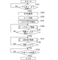
- a block diagram showing the configuration of a vehicle system. A flow chart showing the flow of basic processing.
- a flow chart showing the flow of restart control. Explanatory diagram showing the route to be controlled.
- Example 1 This example is an example of the vehicle system 1 which is an example of the control system of the vehicle 5, and the control method of the vehicle 5. According to this control method and the vehicle system 1, when the vehicle 5 moves from the home to the office, it is possible to leave the garage at the home by automatic driving. This content will be described with reference to FIGS. 1 to 14.
- the route in which the vehicle 5 moves between the areas 60 connected by the highway 61 is illustrated.
- the living road 62 Most of the arterial roads 61 are roads in which magnetic markers 10 are arranged at intervals of, for example, 2 m.
- most of the living roads 62 are roads on which the magnetic marker 10 is not arranged.
- the runway on which the vehicle 5 travels in this way is a runway including the runway on which the magnetic marker 10 is arranged.
- FIG. 2 is an example of the area 60 and shows the position of the vehicle 5 in the area 60.
- the starting point area 60D and the destination point area 60A are used together.
- the code 622 in the case of the starting point area 60D represents, for example, the home, which is the starting point
- the code 622 in the case of the destination area 60A represents, for example, the office, which is the destination point.
- Vehicle driving can be automated (see Figure 1). For example, if you are located in an area 60 where your work place is different from your home 622, after starting from your home 622 in the area 60D, you can use the arterial road 61 to move to the area 60A where your company is located. The vehicle 5 can automatically travel on the route to the office.
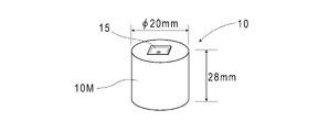
- the magnetic marker 10 (FIG. 3) is a marker in which an RFID tag 15 (Radio Frequency IDentification Tag) is integrated with a columnar magnet 10M having a diameter of 20 mm and a height of 28 mm. .. As shown in FIG. 4, the magnetic marker 10 is arranged in a state of being housed in a hole formed in the road surface 100S.
- the magnet 10M forming the magnetic marker 10 is a ferrite plastic magnet in which magnetic powder of iron oxide, which is a magnetic material, is dispersed in a polymer material as a base material.
- the polymer material is, for example, Chlorinated Polyethylene, Poly Phenylene Sulfide-PPS, or the like.
- a sheet-shaped RFID tag 15 is arranged on the end face of the columnar magnet 10M.
- the RFID tag 15 is an electronic component that wirelessly outputs tag information.
- a coating layer made of a resin material may be provided on the surface.
- the coating layer may be a layer made of a composite material in which fibers are impregnated with a resin material.
- the RFID tag 15 may be arranged on the end face of the magnet 10M on which the coating layer is formed.
- a coating layer may be provided on all or part of the outer surface of the magnet 10M.
- the RFID tag 15 may be embedded inside the magnet 10M.
- a sheet-shaped magnetic marker made of a magnet sheet may be adopted.
- the sheet-shaped RFID tag 15 may be laminated on the surface of the magnet sheet. Further, it may be a magnetic marker in which two magnet sheets are bonded together. In this case, the sheet-shaped RFID tag 15 may be sandwiched between the two magnet sheets.
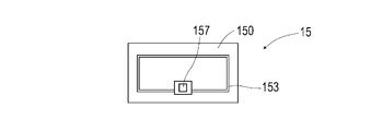
- the RFID tag 15 (FIG. 5) is an electronic component in which an IC chip 157 is mounted on the surface of a tag sheet 150 cut out from, for example, a PET (Polyethylene terephthalate) film.
- a print pattern of the antenna 153 is provided on the surface of the tag sheet 150.
- the antenna 153 has both a power feeding antenna function in which an exciting current is generated by electromagnetic induction from the outside and a communication antenna function for wirelessly transmitting information.
- the RFID tag 15 operates by wireless external power supply, and outputs tag information such as tag ID, which is identification information, to the outside.
- the tag ID externally output by the RFID tag 15 is an example of the identification information of the magnetic marker 10.
- the magnet 10M constituting the magnetic marker 10 as described above is a magnet in which magnetic powder is dispersed in a polymer material. Since such a magnet 10M has a large electrical internal resistance, there is little possibility that an eddy current is generated according to the wireless power supply to the RFID tag 15. Therefore, when this magnet 10M is adopted, electric power can be efficiently supplied to the RFID tag 15 from the outside.
- the magnet 10M is suitable as a magnet for holding the RFID tag 15.
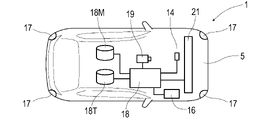
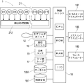
- Vehicle system 1 (FIGS. 6 and 7) includes a control unit 18 for controlling the travel of the vehicle 5, various actuators for travel control capable of external control, a millimeter-wave radar 17, an image sensor 19, and the like.
- the object detection sensor, the tag reader unit 14 that communicates with the RFID tag 15, and the positioning unit 16 for specifying the absolute position or the relative position are included.
- the control unit 18 is a circuit unit composed mainly of an electronic board (not shown) on which electronic components such as a CPU (Central Processing Unit), a ROM (Read Only Memory), and a RAM (Random Access Memory) are mounted. be.
- a storage device storage medium
- a wireless communication circuit, or the like is connected to an electronic board via I / O (Input / Output). ..
- the control unit 18 is provided with a marker database (marker DB) 18M for storing marker information related to each magnetic marker 10 and a map database (map DB) 18T for storing three-dimensional map data using the storage area of the storage device.
- marker DB marker database
- map DB map database
- the 3D map data represents the 3D structure of road accessories such as edge stones, guard rails, central separation zones and signs, and the 3D structure of the surrounding environment such as buildings and overpasses. It is map data.
- the tag ID (tag information), which is the identification information of the attached RFID tag 15, is linked (corresponded) to the marker information stored in the marker DB 18M.
- the corresponding magnetic marker 10 can be specified by referring to the marker DB 18M using the tag ID.
- the marker information includes position data (position information) indicating the laying position of the magnetic marker 10, information indicating the attributes of the laying position (road type, etc.), regulation information such as speed limit, and the like.
- position information position information
- the tag ID is linked to this marker information.
- the tag ID is an example of information that can specify the position of the magnetic marker 10.
- the map data stored in the map DB18T is composed of vector data representing the structure of the road and the surrounding environment.
- this map data the laying position and the like of each magnetic marker 10 are mapped.
- the position in the map data can be specified by specifying the magnetic marker 10. Then, if the position of the vehicle 5 in the map data is specified, the road shape and road structure in front represented by the map data can be grasped.
- the control unit 18 may be capable of receiving real-time traffic conditions such as construction sites and signal lighting states from an external server at any time.
- real-time traffic conditions such as construction sites and signal lighting states from an external server at any time.
- a dynamic map that reflects the real-time traffic conditions can be constructed, and vehicle control using the dynamic map becomes possible.
- Various actuators controlled by the control unit 18 include a throttle actuator 181 for adjusting the engine output (FIG. 7), a steering actuator 183 for changing the steering direction, and a brake actuator 185 for adjusting the braking force. be.
- the control unit 18 can drive the vehicle 5 by appropriately controlling these actuators.
- Sensors connected to the control unit 18 include a magnetic sensor Cn, a millimeter wave radar 17, an image sensor 19, and the like.
- the magnetic sensor Cn is a sensor for detecting magnetism.
- the vehicle 5 incorporates a sensor array 21 in which 15 magnetic sensors Cn are arranged in a straight line.
- the sensor array 21 is a rod-shaped unit that is long in the vehicle width direction, and is attached to the bottom surface of the vehicle 5 in a state of facing the road surface 100S.
- the sensor array 21 includes a detection processing circuit 212 that executes detection processing of the magnetic marker 10.
- the detection processing circuit 212 controls 15 magnetic markers Cn to acquire the magnetic measurement values of each magnetic marker Cn. Then, the detection processing circuit 212 executes the detection processing of the magnetic marker 10 and the like by processing the magnetic measurement value of each magnetic marker Cn.
- the sensor array 21 In the sensor array 21 (FIG. 7), 15 magnetic sensors Cn are arranged at intervals of 10 cm.
- the magnetic measurement values output by the magnetic sensors C1 to C15 form a discrete magnetic distribution in the vehicle width direction.
- the sensor array 21 detection processing circuit 212 detects the magnetic marker 10, it outputs a detection signal indicating that fact and measures the amount of lateral displacement of the vehicle 5 with respect to the magnetic marker 10.
- the sensor array 21 is located directly above the magnetic marker 10
- the position of the magnetic marker 10 in the vehicle width direction is specified based on the distribution of magnetic measurement values (magnetic distribution in the vehicle width direction) output by each magnetic sensor Cn. It is possible.
- the sensor array 21 specifies the amount of lateral displacement of the vehicle with respect to the magnetic marker 10 based on the position of the magnetic marker in the vehicle width direction.
- the magnetic sensor Cn for example, an MI sensor that detects magnetism by using a known MI effect (Magneto Impedance Effect) is suitable.
- the MI effect is a magnetic effect in which the impedance of a magnetic sensitive material such as an amorphous wire changes sensitively in response to an external magnetic field.
- the MI sensor has magnetic sensitivity in the direction of the magnetometer incorporated in a straight line.
- the magnetic sensor Cn may be, for example, a magnetic sensor capable of detecting a magnetic component in one direction such as a vehicle width direction or a vertical direction. It may be a magnetic sensor capable of detecting magnetic components in two directions such as a magnetic component in the traveling direction and a magnetic component in the vehicle width direction. A magnetic sensor capable of detecting magnetic components in three directions, such as being able to detect magnetic components in the vertical direction in addition to the traveling direction and the vehicle width direction, may be used.
- the millimeter wave radar 17 is an object detection sensor that uses millimeter waves with a wavelength of 1 to 10 mm and a frequency of 30 to 300 GHz.
- the millimeter wave radar 17 detects an object by using the reflected radio wave when the millimeter wave is transmitted, and measures the distance to the object.
- the millimeter-wave radar 17 it is possible to detect a person in addition to other vehicles, road structures such as guardrails and curbs.
- millimeter-wave radars 17 are arranged at the front, rear, left, and right corners of the vehicle body so that the surroundings can be monitored.
- the image sensor 19 is a sensor including a front camera for photographing the environment in front.
- the image sensor 19 includes a processing circuit (not shown) or the like that executes image processing.
- the image sensor 19 performs image processing on the captured image to detect white lines, road signs, traffic lights, people, bicycles, preceding vehicles, oncoming vehicles, and the like that divide lanes.
- sensor fusion technology that enhances detection accuracy by using a plurality of sensors, such as performing image processing focusing on the gaze area specified by the millimeter wave sensor 17, is utilized. To.
- the positioning unit 16 includes a GPS (Global Positioning System) unit, an inertial measurement unit, and the like.
- the GPS unit is a unit that measures a vehicle position (vehicle position) using GPS, which is a type of GNSS (Global Navigation Satellite System).
- the inertial measurement unit is a unit that measures the changing speed (angular velocity) of the yaw angle of a vehicle and the acceleration in the traveling direction and the lateral direction. By using the angular velocity and acceleration measured by the inertial measurement unit, it is possible to specify the relative position from the reference position (an example of the amount of displacement due to the movement of the vehicle) and the direction of the vehicle.
- the relative position and the turning angle (change amount of the yaw angle) after passing the reference position such as the laying position of the magnetic marker 10 can be specified with high accuracy.
- an inertial measurement unit it is possible to identify the vehicle position in a tunnel where satellite radio waves cannot be received.
- the tag reader unit 14 is a communication unit that wirelessly communicates with the RFID tag 15 held by the magnetic marker 10 (FIG. 4).
- the tag reader unit 14 wirelessly transmits the electric power required for the operation of the RFID tag 15 to operate the RFID tag 15 and reads the tag ID (tag information) which is the identification information of the RFID tag 15.
- tag ID tag information
- FIG. 6 a unit in which these are integrated may be adopted.
- FIG. 8 shows the flow of (3.1) basic processing when the vehicle 5 moves.
- FIG. 9 shows the flow of (3.2) restart control during the restart period following the parking period.
- FIG. 11 shows the flow of (3.3) normal running control, which runs while detecting the magnetic marker 10. Note that FIG. 10 is a reference diagram in the explanation of restart control. 12 and 13 are explanatory views in the explanation of the normal traveling control.
- the control unit 18 acquires the destination point input by the user of the vehicle 5, for example. (S102).
- the input method of the destination point for example, a method of inputting using a mobile terminal (not shown) connected so as to be communicable by the Bluetooth (R) function, or a touch panel display (not shown) provided on the vehicle 5 is used. There is a method to input above.
- the control unit 18 refers to the three-dimensional map data stored in the map DB 18T, identifies the route to the destination point by calculation, and sets the route as the control target (S103). When specifying the route to the destination point, the control unit 18 also determines the magnetic marker 10 to which the vehicle 5 first arrives by the restart control described later. The magnetic marker 10 determined by the control unit 18 in this way is the optimum magnetic marker to be detected first when the vehicle reaches the destination point.
- the control unit 19 stores the identification information of the magnetic marker 10 determined at the time of specifying the route. Although details will be described later, the identification information of the magnetic marker 10 is information that triggers switching from the restart control in step S105 to the normal travel control in step S107 below.
- control unit 18 reads out the route data representing the route on the three-dimensional map data from the map DB 18T (S104), and starts control so as to drive the vehicle 5 along the corresponding route.
- the control unit 18 executes restart control (described later with reference to FIG. 9) in which the vehicle 5 is driven by automatic running based on the vehicle position positioned by the positioning unit 16 (S105).
- This restart control is a control that does not presuppose the magnetic marker 10, and is executed during the restart period until the magnetic marker 10 can be detected (S106: No ⁇ S105).
- the control unit 18 When the magnetic marker 10 determined at the time of identifying the route to the destination as described above can be detected while the vehicle 5 is traveling by the restart control (S106: Yes), that is, the control unit as described above.
- the control unit 18 performs the control applied to the vehicle 5 from the restart control in step S105.
- the normal traveling control is a control for a road on which a magnetic marker 10 is arranged, such as an arterial road 61. This normal travel control is premised on the continuous detection of the magnetic marker 10. The contents of the normal traveling control will be described later with reference to FIGS. 11 to 13.
- the control unit 18 executes the normal running control during the normal running period from the start of the movement of the vehicle 5 to the first detection of the magnetic marker 10 until the vehicle arrives at the destination point (S108: No ⁇ S107). ). Upon arriving at the destination point, the control unit 18 ends the process in response to the switching of the ignition of the vehicle 5 to the off state (IG off) (S109: Yes). When the IG is off, the control unit 18 stores (saves, stores, records) the vehicle position and the vehicle direction representing the direction (absolute direction) of the vehicle 5 in the storage area.
- the control unit 18 automatically travels the vehicle 5 by inertial navigation based on the last detected magnetic marker 10 (automatic travel control). As will be described in detail later, this automatic traveling control by the control unit 18 is executed as a part of the normal traveling control.
- the restart control (FIGS. 8 and 9) is a control until the magnetic marker 10 can be detected after the ignition of the vehicle 5 is switched to the ON state.
- This restart control is a control for autonomously traveling the vehicle 5 without assuming the magnetic marker 10.
- the restart control is applied, for example, as shown in FIG. 10, after the vehicle 5 parked at the home 622 starts moving, it moves along the arrow R1 and is a highway on which the magnetic marker 10 is arranged. The situation until entering 61 is assumed. After entering the main road 61, the vehicle switches to the normal traveling control described in detail with reference to FIG.
- the arrow R1 is a part of the route to be controlled determined in step S103 in the above-mentioned basic process.
- the control unit 18 first acquires the positioning data by the positioning unit 16 (S201).
- the control unit 18 uses this positioning data to specify the vehicle position and the vehicle orientation (S202).
- the positioning unit 16 includes a GPS unit that outputs position data representing an absolute position, an inertial measurement unit that outputs angular velocity and acceleration, and the like.
- the control unit 18 uses the position data obtained by the GPS unit to specify the vehicle position on the route set in step S103 above. Further, the control unit 18 collates the three-dimensional structure around the vehicle position represented by the three-dimensional map with the surrounding three-dimensional structure specified by the image sensor 19 and the millimeter-wave radar 17 included in the vehicle 5. By this collation, the control unit 18 improves the accuracy of the vehicle position and specifies the vehicle direction representing the direction of the vehicle 5.
- control unit 18 specifies the vehicle position and vehicle orientation by inertial navigation when GPS cannot be used, such as when the vehicle 5 cannot receive satellite radio waves while the vehicle 5 is running under restart control.
- the control unit 18 estimates the relative position of the vehicle 5 after that, based on the latest time when the vehicle position and the vehicle direction can be specified. Then, the latest vehicle position is specified by adding the estimated relative position to the vehicle position at the reference time. The relative position of the vehicle 5 is obtained based on the history of acceleration and angular velocity measured by the inertial measurement unit.
- the control unit 18 estimates the turning angle by using the measurement history of the angular velocity by the inertial measurement unit after the time point of the above reference. Specifically, the turning angle, which is the displacement amount of the yaw angle, can be obtained by integrating the angular velocity.
- the control unit 18 specifies the latest vehicle orientation by adding the estimated turning angle (displacement amount of the yaw angle) to the vehicle orientation at the reference time. At this time, the accuracy of the vehicle position and the vehicle orientation can be improved by grasping the surrounding three-dimensional structure using sensors such as the image sensor 19 and the millimeter-wave radar 17 and collating it with the three-dimensional structure represented by the three-dimensional map. Is possible. It should be noted that the vehicle position or vehicle orientation may be estimated mainly by collating the surrounding three-dimensional structure grasped by using the sensor with the three-dimensional structure represented by the three-dimensional map.
- the control unit 18 specifies the position and orientation of the vehicle 5 on the route by combining the route data read in step S104 with the vehicle position and vehicle orientation specified in step S202. As a result, the control unit 18 identifies the surrounding three-dimensional structure including the front of the vehicle 5, and specifies the direction of the course of the vehicle 5 for moving along the route (S203).
- the control unit 18 controls the vehicle 5 so that it can travel in the direction of the course specified in step S203 (S204). During this control, detection data from the millimeter-wave radar 17 and the image sensor 19 is taken into the control unit 18 at any time, and the vehicle 5 is controlled while ensuring safety. For example, according to the millimeter-wave radar 17, it is possible to detect surrounding vehicles such as a preceding vehicle and an oncoming vehicle, a guardrail, a bicycle, a pedestrian, and the like. According to the image sensor 19, road markings such as signs and pedestrian crossings can be detected, and the state of signals can be recognized.
- the restart control of FIG. 9 is continued until the magnetic marker 10 is detected as described above with reference to the flow chart of the basic process of FIG. 8 (S106: No ⁇ S105 in FIG. 8).
- the restart control (FIG. 9) is switched to the normal traveling control (FIG. 11) (S106: Yes ⁇ S107 in FIG. 8).
- the control unit 18 switches a specific method such as a vehicle position depending on whether or not the magnetic marker 10 is detected during the execution of the normal travel control shown in FIG. 11 (S301).
- the control unit 18 acquires the tag ID (marker information) from the RFID tag 15 held by the magnetic marker 10 (S312).
- the control unit 18 refers to the marker DB 18M by using the acquired tag ID, and specifies the position (laying position) of the detected magnetic marker 10.
- the control unit 18 identifies the vehicle position based on the detected position of the magnetic marker 10 (S313). Specifically, the control unit 18 specifies a position shifted by the amount of lateral displacement of the vehicle 5 with respect to the magnetic marker 10 as a vehicle position with reference to the laying position of the magnetic marker 10.
- the control unit 18 is based on the most recently detected laying position of the magnetic markers 10.
- the relative position of the vehicle 5 is estimated by inertial navigation using the vehicle position (position marked with ⁇ in FIG. 12) specified in the above as a reference position (S302).
- the control unit 18 estimates the relative position and the like based on the angular velocity and acceleration of the inertial measurement unit.
- the control unit 18 specifies the position marked with x, which is moved from the reference position by the relative position estimated in step S302, as the vehicle position (S313).
- an example of a vector representing this relative position is indicated by an arrow.
- the control unit 18 calculates the deviation ⁇ D of the own vehicle position with reference to the route of the control target shown by the broken line in FIG. Then, the control unit 18 calculates the direction of the course based on the deviation ⁇ D (S314). The control unit 18 controls the vehicle 5 to travel in the direction of the course obtained in step S314 (S315). As in step S204, during the execution of the normal driving control, the detection data by the millimeter wave radar 17 and the image sensor 19 is taken into the control unit 18 at any time, and the vehicle 5 is controlled while ensuring safety. ..
- the control unit 18 specifies the vehicle position and the vehicle direction by inertial navigation in the flow of step S301: no detection ⁇ S302 (S313).
- the control unit 18 identifies the surrounding three-dimensional structure including the front of the vehicle 5, and determines the direction of the course of the vehicle 5 for moving along the route (S314).
- the difference in control between the main road 61 on which the magnetic marker 10 is arranged and the road on which the magnetic marker 10 is not arranged, such as a living road 62, is that the amount of lateral displacement of the vehicle 5 with respect to the magnetic marker 10 is predetermined. With or without lateral control to bring it closer to the value.
- On roads where the magnetic marker 10 is not arranged lane recognition by image processing, vehicle position measured by the GPS unit, vehicle orientation (yaw angle) based on the measured value of the inertial measurement unit, etc. are referred to, and the steering angle is steered. Control target is determined.
- the control target of the steering angle is determined by using the amount of lateral displacement with respect to the magnetic marker 10.
- the control method of this example is a control method for the vehicle 5 equipped with the magnetic sensor Cn to travel on the road (runway) on which the magnetic marker 10 is arranged.
- the restart period is set until the vehicle 5 moves and first detects the magnetic marker 10. The control is switched between the normal running period after the detection of the magnetic marker 10 and the normal running period.
- restart control is executed in which the vehicle position is specified based on the position determined in the restart period following the parking period and the vehicle 5 is driven.
- normal running control is executed in which the vehicle position is specified based on the detected position of the magnetic marker 10 and the vehicle 5 is run.
- the restart period to which the restart control is applied is set between the parking period and the normal driving period.
- the control of the vehicle 5 during this restart period is a control that does not presuppose the detection of the magnetic marker 10. If the control is switched between the normal traveling period and the restart period, automatic traveling from the start of movement of the vehicle 5 after the parking period to the detection of the magnetic marker 10 becomes possible. According to such a control method, the area in which the traveling of the vehicle 5 can be controlled can be expanded, and the versatility can be improved. According to the control method of this example, it is possible to realize a high level of automatic driving by using the magnetic marker 10 arranged on the road.
- step S201 (FIG. 9) is immediately executed when the restart control is started in response to the switching to IG on in step S101 (FIG. 8) described above has been described.
- the restart control is immediately started and before the vehicle position is specified (S210: YES)
- the GPS positioning accuracy is first evaluated (S211), and the GPS positioning is performed. It is also possible to decide whether or not to specify the vehicle position based on the data.
- an evaluation of positioning accuracy by GPS for example, there is an evaluation using the number of satellites that can receive satellite radio waves.
- the GPS positioning accuracy that can be expected based on the number of satellites that can receive satellite radio waves, and the estimation accuracy of the vehicle position stored in the storage area at the time of the latest IG off, that is, at the time of transition to the immediately preceding parking period. Evaluation to compare is conceivable.
- an index of positioning accuracy by GPS there is a size of an error circle.
- an index of the accuracy of the vehicle position when the IG is off there is a range of the estimation error of the vehicle position by inertial navigation.
- the vehicle position is determined based on the positioning data by GPS. It is good to specify (S212). That is, at the start of the restart period, the accuracy of the vehicle position determined by GPS is compared with the estimation accuracy of the vehicle position at the time of the transition to the immediately preceding parking period, and the positioning accuracy by GPS is higher. In this case, the vehicle position determined by GPS may be specified as the vehicle position at the start of the restart period.
- the vehicle position recorded when the IG is off. Is good to read (S222). That is, at the start of the restart period, the accuracy of the vehicle position determined by GPS and the estimation accuracy of the vehicle position at the time of transition to the immediately preceding parking period are compared, and at the time of transition to the immediately preceding parking period. When the estimation accuracy of the vehicle position is higher, the estimation accuracy of the vehicle position at the time of transition to the immediately preceding parking period may be specified as the vehicle position at the start of the restart period.
- the process after the vehicle position is specified in step S212 or S222 is the same as the process described with reference to FIG.
- the result of evaluating the GPS positioning accuracy is OK or NG. It is also possible to switch between determining whether (S211) and specifying the vehicle position based on the positioning data by the GPS unit (S212) or reading the vehicle position when the IG is off (S222) according to the determination result. ..
- a configuration in which a sheet-shaped RFID tag 15 is attached to the upper surface of the magnetic marker 10 is illustrated, but a configuration in which the magnetic marker 10 and the RFID tag 15 are integrated is not essential.
- the magnetic marker 10 and the RFID tag 15 may be arranged at the same position, and the RFID tag 15 may be arranged vertically above or below the magnetic marker 10.
- the magnetic marker 10 of this example is a marker in which the RFID tag 15 is integrated. Instead of this, a magnetic marker to which the RFID tag 15 is not attached may be included. For example, it is also possible to provide the RFID tag 15 on the magnetic marker 10 located at the intersection, while arranging the untagged magnetic marker at other locations. Alternatively, the magnetic markers 10 provided with the RFID tags 15 may be arranged at intervals of 5 places, 10 places, etc., while the others may be untagged magnetic markers.
- the main road 61 on which the magnetic marker 10 is arranged is illustrated, while the configuration in which the magnetic marker 10 is not arranged on the living road 62 for moving in the area 60 is illustrated. ..
- magnetic markers 10 may be arranged on all roads. In this case, after starting from the parking lot facing the road, the period from entering the road to the first detection of the magnetic marker, or after resuming the running of the vehicle parked on the shoulder, the magnetic marker is first used. The restart period is the period until detection.
- an auxiliary magnetic marker may be arranged along the direction of the road with the magnetic marker 10 as a reference. If the amount of strike-slip with respect to the magnetic marker 10 and the amount of strike-slip with respect to the auxiliary magnetic marker are known, the direction of the road, which is the direction connecting the magnetic marker 10 and the auxiliary magnetic marker, and the traveling direction of the vehicle are formed. The angle can be obtained by calculation or the like. The distance between the magnetic marker 10 and the auxiliary magnetic marker is good so that it can be expected that there is little change in the steering amount on the vehicle side. For example, the interval may be about 0.2 to 3.0 m, more preferably about 1.0 m.
- an interval of 1.5 to 3.0 m may be set, and on a road having a speed limit of about 10 to 20 km / h, an interval of 0.2 to 0.4 m may be set.
- Example 2 This example is an example in which the content of the restart control is changed based on the control method of the vehicle 5 of the first embodiment. This content will be described with reference to FIG. FIG. 9 is a replacement diagram of FIG. 9 referred to in the description of the first embodiment.
- the restart control of this example is an alternative to the restart control of the first embodiment, which mainly uses GPS positioning, and mainly uses autonomous navigation (dead reckoning) for positioning.
- the control unit of this example is the angular velocity (corresponding to reference numeral 16 in FIGS. 6 and 7) output by the positioning unit (corresponding to reference numeral 16 in FIGS. 6 and 7).
- the control unit can perform positioning by autonomous navigation using angular velocity and vehicle speed pulse.
- the restart control (FIG. 15) of this example is a control executed by the control unit in response to switching to IG on (corresponding to step S101: YES in FIG. 8).
- the control unit first determines whether or not the vehicle position has not been specified, that is, whether or not the vehicle position has not been specified immediately after the start of the restart control (S320). .. If the control unit has not specified the vehicle position (S320: YES), the control unit reads out the vehicle position and vehicle orientation recorded at the latest IG off, that is, when the vehicle is parked (S321).
- the control unit After the vehicle position is specified as described above (S320: NO), the control unit acquires the angular velocity, vehicle speed pulse, etc. by the positioning unit 16 (S322), and specifies the vehicle position and vehicle direction by autonomous navigation (S320: NO). S202). Specifically, the control unit 18 estimates the relative position or the relative direction of the vehicle 5 based on the measurement history of the angular velocity after the latest time when the vehicle position and the vehicle direction can be specified, the output history of the vehicle speed pulse, and the like. .. Then, the control unit identifies the latest vehicle direction by adding the estimated relative directions to the vehicle direction at the reference time. Further, the control unit identifies the position moved by the estimated relative position along the latest vehicle direction with the vehicle position at the reference time as the latest vehicle position.
- the process after the vehicle position and the vehicle direction are specified in step S202 is the same as the process described with reference to FIG. 9 in the first embodiment.
- This method is a method of identifying the movement of a pattern or the like in a road surface image taken at a sufficiently short time interval by an image method such as pattern matching and estimating the displacement of the vehicle based on the movement of the pattern or the like. be.
- This method is similar to, for example, a motion detection method in an optical mouse.
- the optical mouse only the translational movement is detected, but it is also possible to detect the rotational movement in addition to the translational movement.
- the rotational movement can be detected from the road surface image, which is an image of the road surface
- the vehicle orientation can be estimated by autonomous navigation based on the road surface image.
- the road surface image may be, for example, an image captured by taking an image of the road surface directly under the vehicle using an imaging camera mounted on the vehicle.
- a specific wavelength such as infrared rays or laser light
- the amount of change in the vehicle orientation may be estimated based on the front image.
- the amount of change in the vehicle orientation can be estimated by detecting the lateral movement of, for example, a utility pole included in the front image acquired continuously in time.
- the front image can be acquired using an imaging camera mounted on the vehicle so that the front can be photographed.
- Vehicle system 10 Magnetic marker 14 Tag reader unit 15 RFID tag (wireless tag) 16 Positioning unit 17 mm wave radar 18 Control unit (circuit) 19 Image sensor 18M Marker database (Marker DB, database) 18T map database (map DB) 21 Sensor array 212 Detection processing circuit 5 Vehicles 60 Areas 61 Arterial roads 62 Living roads
Landscapes
- Engineering & Computer Science (AREA)
- Physics & Mathematics (AREA)
- General Physics & Mathematics (AREA)
- Radar, Positioning & Navigation (AREA)
- Remote Sensing (AREA)
- Automation & Control Theory (AREA)
- Aviation & Aerospace Engineering (AREA)
- Theoretical Computer Science (AREA)
- Mechanical Engineering (AREA)
- Transportation (AREA)
- Computer Vision & Pattern Recognition (AREA)
- Microelectronics & Electronic Packaging (AREA)
- Computer Networks & Wireless Communication (AREA)
- Computer Hardware Design (AREA)
- Multimedia (AREA)
- Chemical & Material Sciences (AREA)
- Combustion & Propulsion (AREA)
- Human Computer Interaction (AREA)
- Traffic Control Systems (AREA)
- Electromagnetism (AREA)
- Control Of Driving Devices And Active Controlling Of Vehicle (AREA)
- Control Of Position, Course, Altitude, Or Attitude Of Moving Bodies (AREA)
Priority Applications (5)
| Application Number | Priority Date | Filing Date | Title |
|---|---|---|---|
| EP22739508.4A EP4280012A4 (en) | 2021-01-18 | 2022-01-14 | CONTROL PROCEDURE AND CONTROL SYSTEM |
| US18/261,500 US20240400046A1 (en) | 2021-01-18 | 2022-01-14 | Control method and control system |
| KR1020237023344A KR102937181B1 (ko) | 2021-01-18 | 2022-01-14 | 제어 방법 및 제어 시스템 |
| JP2022575657A JP7795112B2 (ja) | 2021-01-18 | 2022-01-14 | 制御方法及び制御システム |
| CN202280009242.XA CN116783567A (zh) | 2021-01-18 | 2022-01-14 | 控制方法以及控制系统 |
Applications Claiming Priority (2)
| Application Number | Priority Date | Filing Date | Title |
|---|---|---|---|
| JP2021-005587 | 2021-01-18 | ||
| JP2021005587 | 2021-01-18 |
Publications (1)
| Publication Number | Publication Date |
|---|---|
| WO2022154103A1 true WO2022154103A1 (ja) | 2022-07-21 |
Family
ID=82448495
Family Applications (1)
| Application Number | Title | Priority Date | Filing Date |
|---|---|---|---|
| PCT/JP2022/001230 Ceased WO2022154103A1 (ja) | 2021-01-18 | 2022-01-14 | 制御方法及び制御システム |
Country Status (6)
| Country | Link |
|---|---|
| US (1) | US20240400046A1 (https=) |
| EP (1) | EP4280012A4 (https=) |
| JP (1) | JP7795112B2 (https=) |
| KR (1) | KR102937181B1 (https=) |
| CN (1) | CN116783567A (https=) |
| WO (1) | WO2022154103A1 (https=) |
Families Citing this family (1)
| Publication number | Priority date | Publication date | Assignee | Title |
|---|---|---|---|---|
| GB2626676A (en) * | 2024-02-08 | 2024-07-31 | Chen Hongming | A system and method for guiding navigation of automated guided vehicles (AGVS) |
Citations (7)
| Publication number | Priority date | Publication date | Assignee | Title |
|---|---|---|---|---|
| JPH0566713A (ja) * | 1991-09-10 | 1993-03-19 | Hitachi Ltd | ナビゲーシヨン装置 |
| JP2002334400A (ja) | 2001-05-10 | 2002-11-22 | Mitsubishi Motors Corp | 運転支援装置 |
| JP2008002992A (ja) * | 2006-06-23 | 2008-01-10 | Toyota Motor Corp | 姿勢角検出装置と姿勢角検出方法 |
| JP2013184491A (ja) * | 2012-03-06 | 2013-09-19 | Nissan Motor Co Ltd | 車両走行支援装置 |
| WO2016038931A1 (ja) * | 2014-09-11 | 2016-03-17 | 本田技研工業株式会社 | 運転支援装置 |
| JP2020098566A (ja) * | 2018-09-28 | 2020-06-25 | 先進モビリティ株式会社 | 自動運転システム |
| WO2020175438A1 (ja) * | 2019-02-27 | 2020-09-03 | 愛知製鋼株式会社 | 点群データの取得方法及び点群データ取得システム |
Family Cites Families (16)
| Publication number | Priority date | Publication date | Assignee | Title |
|---|---|---|---|---|
| JP3550916B2 (ja) * | 1996-11-12 | 2004-08-04 | トヨタ自動車株式会社 | 車両用盗難検出装置 |
| US20130060461A1 (en) * | 2011-09-07 | 2013-03-07 | INRO Technologies Limited | Method and apparatus for using pre-positioned objects to localize an industrial vehicle |
| JP6067315B2 (ja) * | 2012-10-12 | 2017-01-25 | 富士通テン株式会社 | 車両制御装置、及び、車両制御方法 |
| JP6156067B2 (ja) * | 2013-11-01 | 2017-07-05 | 富士通株式会社 | 移動量推定装置及び移動量推定方法 |
| US9796400B2 (en) * | 2013-11-27 | 2017-10-24 | Solfice Research, Inc. | Real time machine vision and point-cloud analysis for remote sensing and vehicle control |
| CN105005302B (zh) * | 2015-05-29 | 2017-11-14 | 李祥榕 | 一种基于gps和rfid的车辆自动控制系统及方法 |
| US9964648B2 (en) * | 2015-06-16 | 2018-05-08 | Insero LLC | Guidiance system and method based on dead reckoning positioning and heading augmented by GNSS and predictive path selection |
| JP6707887B2 (ja) | 2016-02-12 | 2020-06-10 | 株式会社デンソー | 車両用装置 |
| JP6916784B2 (ja) * | 2016-06-03 | 2021-08-11 | 愛知製鋼株式会社 | 位置捕捉方法及びシステム |
| JP6928306B2 (ja) * | 2017-03-28 | 2021-09-01 | 愛知製鋼株式会社 | 磁気マーカの施工方法及び作業システム |
| JP6828643B2 (ja) | 2017-09-12 | 2021-02-10 | 愛知製鋼株式会社 | 位置捕捉システム及び位置捕捉方法 |
| US11511627B2 (en) | 2017-11-17 | 2022-11-29 | Aisin Corporation | Display device and computer program |
| JP7047392B2 (ja) * | 2018-01-16 | 2022-04-05 | 愛知製鋼株式会社 | 車両位置管理システム及び車両位置管理方法 |
| JP7155596B2 (ja) | 2018-05-02 | 2022-10-19 | 愛知製鋼株式会社 | 自動駐車システム |
| JP7147275B2 (ja) | 2018-06-04 | 2022-10-05 | 愛知製鋼株式会社 | ジャイロセンサの較正方法 |
| US10488202B1 (en) * | 2019-01-08 | 2019-11-26 | Adam Benjamin Tannenbaum | System and method of use for self-contained vehicular navigation system |
-
2022
- 2022-01-14 KR KR1020237023344A patent/KR102937181B1/ko active Active
- 2022-01-14 CN CN202280009242.XA patent/CN116783567A/zh active Pending
- 2022-01-14 EP EP22739508.4A patent/EP4280012A4/en not_active Withdrawn
- 2022-01-14 WO PCT/JP2022/001230 patent/WO2022154103A1/ja not_active Ceased
- 2022-01-14 JP JP2022575657A patent/JP7795112B2/ja active Active
- 2022-01-14 US US18/261,500 patent/US20240400046A1/en active Pending
Patent Citations (7)
| Publication number | Priority date | Publication date | Assignee | Title |
|---|---|---|---|---|
| JPH0566713A (ja) * | 1991-09-10 | 1993-03-19 | Hitachi Ltd | ナビゲーシヨン装置 |
| JP2002334400A (ja) | 2001-05-10 | 2002-11-22 | Mitsubishi Motors Corp | 運転支援装置 |
| JP2008002992A (ja) * | 2006-06-23 | 2008-01-10 | Toyota Motor Corp | 姿勢角検出装置と姿勢角検出方法 |
| JP2013184491A (ja) * | 2012-03-06 | 2013-09-19 | Nissan Motor Co Ltd | 車両走行支援装置 |
| WO2016038931A1 (ja) * | 2014-09-11 | 2016-03-17 | 本田技研工業株式会社 | 運転支援装置 |
| JP2020098566A (ja) * | 2018-09-28 | 2020-06-25 | 先進モビリティ株式会社 | 自動運転システム |
| WO2020175438A1 (ja) * | 2019-02-27 | 2020-09-03 | 愛知製鋼株式会社 | 点群データの取得方法及び点群データ取得システム |
Non-Patent Citations (1)
| Title |
|---|
| See also references of EP4280012A4 |
Also Published As
| Publication number | Publication date |
|---|---|
| KR20230118642A (ko) | 2023-08-11 |
| KR102937181B1 (ko) | 2026-03-09 |
| EP4280012A4 (en) | 2024-12-04 |
| JP7795112B2 (ja) | 2026-01-07 |
| CN116783567A (zh) | 2023-09-19 |
| JPWO2022154103A1 (https=) | 2022-07-21 |
| EP4280012A1 (en) | 2023-11-22 |
| US20240400046A1 (en) | 2024-12-05 |
Similar Documents
| Publication | Publication Date | Title |
|---|---|---|
| CN112041909B (zh) | 自动驻车系统及自动驻车方法 | |
| US20240034309A1 (en) | Navigation in vehicle crossing scenarios | |
| EP3520095B1 (en) | Dynamic routing for autonomous vehicles | |
| RU2659341C2 (ru) | Система автоматического управления транспортным средством | |
| US20200257301A1 (en) | Navigation by augmented path prediction | |
| CN110928286B (zh) | 用于控制车辆的自动驾驶的方法、设备、介质和系统 | |
| US20250014357A1 (en) | Long-range object detection, localization, tracking and classification for autonomous vehicles | |
| US20220266824A1 (en) | Road information generation apparatus | |
| CN114792475B (zh) | 自动停车系统 | |
| US12246746B2 (en) | Operation system and operation system control method | |
| CN106840177A (zh) | 汽车同步建图与障碍识别方法 | |
| US20220291015A1 (en) | Map generation apparatus and vehicle position recognition apparatus | |
| JP2022039469A (ja) | 車両走行制御装置 | |
| WO2022154103A1 (ja) | 制御方法及び制御システム | |
| US12123739B2 (en) | Map generation apparatus | |
| CN116892919A (zh) | 地图生成装置 | |
| US20220307861A1 (en) | Map generation apparatus | |
| JP7817594B2 (ja) | 車両用システム | |
| CN118116186A (zh) | 车道推定装置和地图生成装置 | |
| JP7381939B2 (ja) | 3次元構造推定方法及び3次元構造推定システム | |
| EP4111283A1 (en) | Improved vehicle operation zone detection | |
| JP2026049251A (ja) | 移動体制御装置、移動体制御方法、及びプログラム | |
| CN114987528A (zh) | 地图生成装置 | |
| Kampfer et al. | Principles of systems that enable autonomous driving of vehicles | |
| JP2022123238A (ja) | 区画線認識装置 |
Legal Events
| Date | Code | Title | Description |
|---|---|---|---|
| 121 | Ep: the epo has been informed by wipo that ep was designated in this application |
Ref document number: 22739508 Country of ref document: EP Kind code of ref document: A1 |
|
| DPE1 | Request for preliminary examination filed after expiration of 19th month from priority date (pct application filed from 20040101) | ||
| ENP | Entry into the national phase |
Ref document number: 2022575657 Country of ref document: JP Kind code of ref document: A |
|
| WWE | Wipo information: entry into national phase |
Ref document number: 202280009242.X Country of ref document: CN |
|
| ENP | Entry into the national phase |
Ref document number: 20237023344 Country of ref document: KR Kind code of ref document: A |
|
| NENP | Non-entry into the national phase |
Ref country code: DE |
|
| ENP | Entry into the national phase |
Ref document number: 2022739508 Country of ref document: EP Effective date: 20230818 |
|
| WWE | Wipo information: entry into national phase |
Ref document number: 11202305308R Country of ref document: SG |
|
| WWW | Wipo information: withdrawn in national office |
Ref document number: 2022739508 Country of ref document: EP |