WO2022154103A1 - Control method and control system - Google Patents
Control method and control system Download PDFInfo
- Publication number
- WO2022154103A1 WO2022154103A1 PCT/JP2022/001230 JP2022001230W WO2022154103A1 WO 2022154103 A1 WO2022154103 A1 WO 2022154103A1 JP 2022001230 W JP2022001230 W JP 2022001230W WO 2022154103 A1 WO2022154103 A1 WO 2022154103A1
- Authority
- WO
- WIPO (PCT)
- Prior art keywords
- vehicle
- magnetic marker
- period
- control
- magnetic
- Prior art date
Links
- 238000000034 method Methods 0.000 title claims description 50
- 230000005291 magnetic effect Effects 0.000 claims abstract description 187
- 239000003550 marker Substances 0.000 claims abstract description 150
- 238000006073 displacement reaction Methods 0.000 claims description 15
- 238000007562 laser obscuration time method Methods 0.000 claims description 8
- 230000005389 magnetism Effects 0.000 claims description 6
- 230000007704 transition Effects 0.000 claims description 3
- 238000001514 detection method Methods 0.000 description 25
- 238000012545 processing Methods 0.000 description 19
- 238000005259 measurement Methods 0.000 description 16
- 230000033001 locomotion Effects 0.000 description 12
- 230000006870 function Effects 0.000 description 11
- 230000008569 process Effects 0.000 description 8
- 230000001133 acceleration Effects 0.000 description 5
- 230000008859 change Effects 0.000 description 5
- 239000011247 coating layer Substances 0.000 description 4
- 238000010586 diagram Methods 0.000 description 4
- 230000000694 effects Effects 0.000 description 4
- 239000000463 material Substances 0.000 description 4
- 230000004044 response Effects 0.000 description 4
- 238000004891 communication Methods 0.000 description 3
- 238000011156 evaluation Methods 0.000 description 3
- 239000002861 polymer material Substances 0.000 description 3
- UQSXHKLRYXJYBZ-UHFFFAOYSA-N Iron oxide Chemical compound [Fe]=O UQSXHKLRYXJYBZ-UHFFFAOYSA-N 0.000 description 2
- -1 Poly Phenylene Polymers 0.000 description 2
- 238000003384 imaging method Methods 0.000 description 2
- 239000006247 magnetic powder Substances 0.000 description 2
- 230000003287 optical effect Effects 0.000 description 2
- 229920000139 polyethylene terephthalate Polymers 0.000 description 2
- 239000005020 polyethylene terephthalate Substances 0.000 description 2
- 239000011347 resin Substances 0.000 description 2
- 229920005989 resin Polymers 0.000 description 2
- 239000004709 Chlorinated polyethylene Substances 0.000 description 1
- 229920000265 Polyparaphenylene Polymers 0.000 description 1
- 230000033228 biological regulation Effects 0.000 description 1
- 239000002131 composite material Substances 0.000 description 1
- 238000010276 construction Methods 0.000 description 1
- 230000005674 electromagnetic induction Effects 0.000 description 1
- 238000005516 engineering process Methods 0.000 description 1
- 239000000835 fiber Substances 0.000 description 1
- 230000004927 fusion Effects 0.000 description 1
- 239000010410 layer Substances 0.000 description 1
- 239000000696 magnetic material Substances 0.000 description 1
- 239000000203 mixture Substances 0.000 description 1
- 239000004033 plastic Substances 0.000 description 1
- 229920003023 plastic Polymers 0.000 description 1
- 230000035945 sensitivity Effects 0.000 description 1
- 238000000926 separation method Methods 0.000 description 1
- 239000007787 solid Substances 0.000 description 1
- 229910000859 α-Fe Inorganic materials 0.000 description 1
Images


Classifications
-
- B—PERFORMING OPERATIONS; TRANSPORTING
- B60—VEHICLES IN GENERAL
- B60W—CONJOINT CONTROL OF VEHICLE SUB-UNITS OF DIFFERENT TYPE OR DIFFERENT FUNCTION; CONTROL SYSTEMS SPECIALLY ADAPTED FOR HYBRID VEHICLES; ROAD VEHICLE DRIVE CONTROL SYSTEMS FOR PURPOSES NOT RELATED TO THE CONTROL OF A PARTICULAR SUB-UNIT
- B60W30/00—Purposes of road vehicle drive control systems not related to the control of a particular sub-unit, e.g. of systems using conjoint control of vehicle sub-units, or advanced driver assistance systems for ensuring comfort, stability and safety or drive control systems for propelling or retarding the vehicle
- B60W30/10—Path keeping
-
- G—PHYSICS
- G06—COMPUTING; CALCULATING OR COUNTING
- G06T—IMAGE DATA PROCESSING OR GENERATION, IN GENERAL
- G06T7/00—Image analysis
- G06T7/70—Determining position or orientation of objects or cameras
-
- B—PERFORMING OPERATIONS; TRANSPORTING
- B60—VEHICLES IN GENERAL
- B60W—CONJOINT CONTROL OF VEHICLE SUB-UNITS OF DIFFERENT TYPE OR DIFFERENT FUNCTION; CONTROL SYSTEMS SPECIALLY ADAPTED FOR HYBRID VEHICLES; ROAD VEHICLE DRIVE CONTROL SYSTEMS FOR PURPOSES NOT RELATED TO THE CONTROL OF A PARTICULAR SUB-UNIT
- B60W60/00—Drive control systems specially adapted for autonomous road vehicles
- B60W60/001—Planning or execution of driving tasks
-
- B—PERFORMING OPERATIONS; TRANSPORTING
- B62—LAND VEHICLES FOR TRAVELLING OTHERWISE THAN ON RAILS
- B62D—MOTOR VEHICLES; TRAILERS
- B62D15/00—Steering not otherwise provided for
- B62D15/02—Steering position indicators ; Steering position determination; Steering aids
- B62D15/027—Parking aids, e.g. instruction means
- B62D15/0285—Parking performed automatically
-
- G—PHYSICS
- G01—MEASURING; TESTING
- G01C—MEASURING DISTANCES, LEVELS OR BEARINGS; SURVEYING; NAVIGATION; GYROSCOPIC INSTRUMENTS; PHOTOGRAMMETRY OR VIDEOGRAMMETRY
- G01C21/00—Navigation; Navigational instruments not provided for in groups G01C1/00 - G01C19/00
- G01C21/10—Navigation; Navigational instruments not provided for in groups G01C1/00 - G01C19/00 by using measurements of speed or acceleration
- G01C21/12—Navigation; Navigational instruments not provided for in groups G01C1/00 - G01C19/00 by using measurements of speed or acceleration executed aboard the object being navigated; Dead reckoning
- G01C21/16—Navigation; Navigational instruments not provided for in groups G01C1/00 - G01C19/00 by using measurements of speed or acceleration executed aboard the object being navigated; Dead reckoning by integrating acceleration or speed, i.e. inertial navigation
- G01C21/165—Navigation; Navigational instruments not provided for in groups G01C1/00 - G01C19/00 by using measurements of speed or acceleration executed aboard the object being navigated; Dead reckoning by integrating acceleration or speed, i.e. inertial navigation combined with non-inertial navigation instruments
-
- G—PHYSICS
- G01—MEASURING; TESTING
- G01C—MEASURING DISTANCES, LEVELS OR BEARINGS; SURVEYING; NAVIGATION; GYROSCOPIC INSTRUMENTS; PHOTOGRAMMETRY OR VIDEOGRAMMETRY
- G01C21/00—Navigation; Navigational instruments not provided for in groups G01C1/00 - G01C19/00
- G01C21/26—Navigation; Navigational instruments not provided for in groups G01C1/00 - G01C19/00 specially adapted for navigation in a road network
- G01C21/34—Route searching; Route guidance
- G01C21/36—Input/output arrangements for on-board computers
-
- G05D1/247—
-
- G05D1/646—
-
- G—PHYSICS
- G06—COMPUTING; CALCULATING OR COUNTING
- G06K—GRAPHICAL DATA READING; PRESENTATION OF DATA; RECORD CARRIERS; HANDLING RECORD CARRIERS
- G06K19/00—Record carriers for use with machines and with at least a part designed to carry digital markings
- G06K19/06—Record carriers for use with machines and with at least a part designed to carry digital markings characterised by the kind of the digital marking, e.g. shape, nature, code
- G06K19/067—Record carriers with conductive marks, printed circuits or semiconductor circuit elements, e.g. credit or identity cards also with resonating or responding marks without active components
- G06K19/07—Record carriers with conductive marks, printed circuits or semiconductor circuit elements, e.g. credit or identity cards also with resonating or responding marks without active components with integrated circuit chips
- G06K19/0723—Record carriers with conductive marks, printed circuits or semiconductor circuit elements, e.g. credit or identity cards also with resonating or responding marks without active components with integrated circuit chips the record carrier comprising an arrangement for non-contact communication, e.g. wireless communication circuits on transponder cards, non-contact smart cards or RFIDs
-
- G—PHYSICS
- G06—COMPUTING; CALCULATING OR COUNTING
- G06T—IMAGE DATA PROCESSING OR GENERATION, IN GENERAL
- G06T7/00—Image analysis
- G06T7/20—Analysis of motion
- G06T7/269—Analysis of motion using gradient-based methods
-
- G—PHYSICS
- G08—SIGNALLING
- G08G—TRAFFIC CONTROL SYSTEMS
- G08G1/00—Traffic control systems for road vehicles
- G08G1/01—Detecting movement of traffic to be counted or controlled
- G08G1/042—Detecting movement of traffic to be counted or controlled using inductive or magnetic detectors
-
- G—PHYSICS
- G08—SIGNALLING
- G08G—TRAFFIC CONTROL SYSTEMS
- G08G1/00—Traffic control systems for road vehicles
- G08G1/09—Arrangements for giving variable traffic instructions
- G08G1/0962—Arrangements for giving variable traffic instructions having an indicator mounted inside the vehicle, e.g. giving voice messages
- G08G1/0968—Systems involving transmission of navigation instructions to the vehicle
- G08G1/0969—Systems involving transmission of navigation instructions to the vehicle having a display in the form of a map
-
- G—PHYSICS
- G08—SIGNALLING
- G08G—TRAFFIC CONTROL SYSTEMS
- G08G1/00—Traffic control systems for road vehicles
- G08G1/16—Anti-collision systems
- G08G1/166—Anti-collision systems for active traffic, e.g. moving vehicles, pedestrians, bikes
-
- G—PHYSICS
- G08—SIGNALLING
- G08G—TRAFFIC CONTROL SYSTEMS
- G08G1/00—Traffic control systems for road vehicles
- G08G1/16—Anti-collision systems
- G08G1/167—Driving aids for lane monitoring, lane changing, e.g. blind spot detection
-
- B—PERFORMING OPERATIONS; TRANSPORTING
- B60—VEHICLES IN GENERAL
- B60W—CONJOINT CONTROL OF VEHICLE SUB-UNITS OF DIFFERENT TYPE OR DIFFERENT FUNCTION; CONTROL SYSTEMS SPECIALLY ADAPTED FOR HYBRID VEHICLES; ROAD VEHICLE DRIVE CONTROL SYSTEMS FOR PURPOSES NOT RELATED TO THE CONTROL OF A PARTICULAR SUB-UNIT
- B60W2420/00—Indexing codes relating to the type of sensors based on the principle of their operation
- B60W2420/50—Magnetic or electromagnetic sensors
-
- B—PERFORMING OPERATIONS; TRANSPORTING
- B60—VEHICLES IN GENERAL
- B60W—CONJOINT CONTROL OF VEHICLE SUB-UNITS OF DIFFERENT TYPE OR DIFFERENT FUNCTION; CONTROL SYSTEMS SPECIALLY ADAPTED FOR HYBRID VEHICLES; ROAD VEHICLE DRIVE CONTROL SYSTEMS FOR PURPOSES NOT RELATED TO THE CONTROL OF A PARTICULAR SUB-UNIT
- B60W2556/00—Input parameters relating to data
- B60W2556/45—External transmission of data to or from the vehicle
- B60W2556/50—External transmission of data to or from the vehicle for navigation systems
-
- G05D2107/13—
-
- G05D2109/10—
-
- G05D2111/34—
-
- G—PHYSICS
- G06—COMPUTING; CALCULATING OR COUNTING
- G06T—IMAGE DATA PROCESSING OR GENERATION, IN GENERAL
- G06T2207/00—Indexing scheme for image analysis or image enhancement
- G06T2207/10—Image acquisition modality
- G06T2207/10024—Color image
-
- G—PHYSICS
- G06—COMPUTING; CALCULATING OR COUNTING
- G06T—IMAGE DATA PROCESSING OR GENERATION, IN GENERAL
- G06T2207/00—Indexing scheme for image analysis or image enhancement
- G06T2207/10—Image acquisition modality
- G06T2207/10028—Range image; Depth image; 3D point clouds
-
- G—PHYSICS
- G06—COMPUTING; CALCULATING OR COUNTING
- G06T—IMAGE DATA PROCESSING OR GENERATION, IN GENERAL
- G06T2207/00—Indexing scheme for image analysis or image enhancement
- G06T2207/30—Subject of image; Context of image processing
- G06T2207/30248—Vehicle exterior or interior
- G06T2207/30252—Vehicle exterior; Vicinity of vehicle
Definitions
- the present invention relates to a control method and a control system for traveling a vehicle by using a magnetic marker arranged on a track.
- the present invention has been made in view of the above-mentioned conventional problems, and is an invention for providing a control method and a control system for realizing a high level of automatic operation by driving support control using a magnetic marker. ..
- One aspect of the present invention is a control method for a vehicle equipped with a magnetic sensor to travel on a track including a track in which a magnetic marker acting on magnetism is arranged in the periphery.
- One aspect of the present invention is a control system for a vehicle equipped with a magnetic sensor to travel on a track including a track in which a magnetic marker acting on magnetism is arranged in the periphery. Transition to the immediately preceding parking period in the restart period from when the function is restarted after the parking period in which the function for controlling the running of the vehicle is stopped until the vehicle moves and the magnetic marker is first detected.
- a circuit that specifies the position of the vehicle based on the position of the vehicle at that time or the position determined during the restart period and executes control to drive the vehicle. In the normal running period after the vehicle first detects the magnetic marker after the restart period, the position of the vehicle is specified based on the position of any of the detected magnetic markers and the control for running the vehicle is executed. Circuit and The control system includes a circuit that executes control switching when the restart period shifts to the normal running period.
- the present invention is an invention of a control method or control system for a vehicle to travel on a track on which a magnetic marker is arranged.
- the restart is performed until the vehicle moves and the magnetic marker is first detected.
- the control is switched between the period and the normal running period after the vehicle detects the magnetic marker.
- control is executed in which the position of the vehicle is specified based on the position of the vehicle at the time of transition to the immediately preceding parking period or the position determined in the restart period, and the vehicle is driven.
- control is executed in which the position of the vehicle is specified based on the detected position of the magnetic marker and the vehicle is driven.
- the restart period is set between the parking period and the normal running period.
- the control of the vehicle during this restart period is a control that does not presuppose the detection of the magnetic marker.
- control method and control system of the present invention it is possible to realize a higher level of automatic operation by using the magnetic markers arranged on the track.
- Explanatory map of roads in the area. The perspective view which shows the magnetic marker.
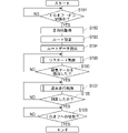
- a block diagram showing the configuration of a vehicle system. A flow chart showing the flow of basic processing.
- a flow chart showing the flow of restart control. Explanatory diagram showing the route to be controlled.
- Example 1 This example is an example of the vehicle system 1 which is an example of the control system of the vehicle 5, and the control method of the vehicle 5. According to this control method and the vehicle system 1, when the vehicle 5 moves from the home to the office, it is possible to leave the garage at the home by automatic driving. This content will be described with reference to FIGS. 1 to 14.
- the route in which the vehicle 5 moves between the areas 60 connected by the highway 61 is illustrated.
- the living road 62 Most of the arterial roads 61 are roads in which magnetic markers 10 are arranged at intervals of, for example, 2 m.
- most of the living roads 62 are roads on which the magnetic marker 10 is not arranged.
- the runway on which the vehicle 5 travels in this way is a runway including the runway on which the magnetic marker 10 is arranged.
- FIG. 2 is an example of the area 60 and shows the position of the vehicle 5 in the area 60.
- the starting point area 60D and the destination point area 60A are used together.
- the code 622 in the case of the starting point area 60D represents, for example, the home, which is the starting point
- the code 622 in the case of the destination area 60A represents, for example, the office, which is the destination point.
- Vehicle driving can be automated (see Figure 1). For example, if you are located in an area 60 where your work place is different from your home 622, after starting from your home 622 in the area 60D, you can use the arterial road 61 to move to the area 60A where your company is located. The vehicle 5 can automatically travel on the route to the office.
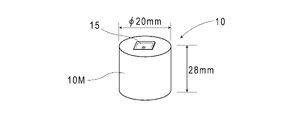
- the magnetic marker 10 (FIG. 3) is a marker in which an RFID tag 15 (Radio Frequency IDentification Tag) is integrated with a columnar magnet 10M having a diameter of 20 mm and a height of 28 mm. .. As shown in FIG. 4, the magnetic marker 10 is arranged in a state of being housed in a hole formed in the road surface 100S.
- the magnet 10M forming the magnetic marker 10 is a ferrite plastic magnet in which magnetic powder of iron oxide, which is a magnetic material, is dispersed in a polymer material as a base material.
- the polymer material is, for example, Chlorinated Polyethylene, Poly Phenylene Sulfide-PPS, or the like.
- a sheet-shaped RFID tag 15 is arranged on the end face of the columnar magnet 10M.
- the RFID tag 15 is an electronic component that wirelessly outputs tag information.
- a coating layer made of a resin material may be provided on the surface.
- the coating layer may be a layer made of a composite material in which fibers are impregnated with a resin material.
- the RFID tag 15 may be arranged on the end face of the magnet 10M on which the coating layer is formed.
- a coating layer may be provided on all or part of the outer surface of the magnet 10M.
- the RFID tag 15 may be embedded inside the magnet 10M.
- a sheet-shaped magnetic marker made of a magnet sheet may be adopted.
- the sheet-shaped RFID tag 15 may be laminated on the surface of the magnet sheet. Further, it may be a magnetic marker in which two magnet sheets are bonded together. In this case, the sheet-shaped RFID tag 15 may be sandwiched between the two magnet sheets.
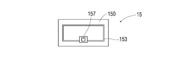
- the RFID tag 15 (FIG. 5) is an electronic component in which an IC chip 157 is mounted on the surface of a tag sheet 150 cut out from, for example, a PET (Polyethylene terephthalate) film.
- a print pattern of the antenna 153 is provided on the surface of the tag sheet 150.
- the antenna 153 has both a power feeding antenna function in which an exciting current is generated by electromagnetic induction from the outside and a communication antenna function for wirelessly transmitting information.
- the RFID tag 15 operates by wireless external power supply, and outputs tag information such as tag ID, which is identification information, to the outside.
- the tag ID externally output by the RFID tag 15 is an example of the identification information of the magnetic marker 10.
- the magnet 10M constituting the magnetic marker 10 as described above is a magnet in which magnetic powder is dispersed in a polymer material. Since such a magnet 10M has a large electrical internal resistance, there is little possibility that an eddy current is generated according to the wireless power supply to the RFID tag 15. Therefore, when this magnet 10M is adopted, electric power can be efficiently supplied to the RFID tag 15 from the outside.
- the magnet 10M is suitable as a magnet for holding the RFID tag 15.
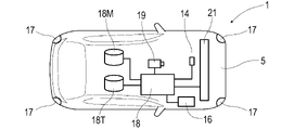
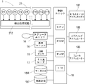
- Vehicle system 1 (FIGS. 6 and 7) includes a control unit 18 for controlling the travel of the vehicle 5, various actuators for travel control capable of external control, a millimeter-wave radar 17, an image sensor 19, and the like.
- the object detection sensor, the tag reader unit 14 that communicates with the RFID tag 15, and the positioning unit 16 for specifying the absolute position or the relative position are included.
- the control unit 18 is a circuit unit composed mainly of an electronic board (not shown) on which electronic components such as a CPU (Central Processing Unit), a ROM (Read Only Memory), and a RAM (Random Access Memory) are mounted. be.
- a storage device storage medium
- a wireless communication circuit, or the like is connected to an electronic board via I / O (Input / Output). ..
- the control unit 18 is provided with a marker database (marker DB) 18M for storing marker information related to each magnetic marker 10 and a map database (map DB) 18T for storing three-dimensional map data using the storage area of the storage device.
- marker DB marker database
- map DB map database
- the 3D map data represents the 3D structure of road accessories such as edge stones, guard rails, central separation zones and signs, and the 3D structure of the surrounding environment such as buildings and overpasses. It is map data.
- the tag ID (tag information), which is the identification information of the attached RFID tag 15, is linked (corresponded) to the marker information stored in the marker DB 18M.
- the corresponding magnetic marker 10 can be specified by referring to the marker DB 18M using the tag ID.
- the marker information includes position data (position information) indicating the laying position of the magnetic marker 10, information indicating the attributes of the laying position (road type, etc.), regulation information such as speed limit, and the like.
- position information position information
- the tag ID is linked to this marker information.
- the tag ID is an example of information that can specify the position of the magnetic marker 10.
- the map data stored in the map DB18T is composed of vector data representing the structure of the road and the surrounding environment.
- this map data the laying position and the like of each magnetic marker 10 are mapped.
- the position in the map data can be specified by specifying the magnetic marker 10. Then, if the position of the vehicle 5 in the map data is specified, the road shape and road structure in front represented by the map data can be grasped.
- the control unit 18 may be capable of receiving real-time traffic conditions such as construction sites and signal lighting states from an external server at any time.
- real-time traffic conditions such as construction sites and signal lighting states from an external server at any time.
- a dynamic map that reflects the real-time traffic conditions can be constructed, and vehicle control using the dynamic map becomes possible.
- Various actuators controlled by the control unit 18 include a throttle actuator 181 for adjusting the engine output (FIG. 7), a steering actuator 183 for changing the steering direction, and a brake actuator 185 for adjusting the braking force. be.
- the control unit 18 can drive the vehicle 5 by appropriately controlling these actuators.
- Sensors connected to the control unit 18 include a magnetic sensor Cn, a millimeter wave radar 17, an image sensor 19, and the like.
- the magnetic sensor Cn is a sensor for detecting magnetism.
- the vehicle 5 incorporates a sensor array 21 in which 15 magnetic sensors Cn are arranged in a straight line.
- the sensor array 21 is a rod-shaped unit that is long in the vehicle width direction, and is attached to the bottom surface of the vehicle 5 in a state of facing the road surface 100S.
- the sensor array 21 includes a detection processing circuit 212 that executes detection processing of the magnetic marker 10.
- the detection processing circuit 212 controls 15 magnetic markers Cn to acquire the magnetic measurement values of each magnetic marker Cn. Then, the detection processing circuit 212 executes the detection processing of the magnetic marker 10 and the like by processing the magnetic measurement value of each magnetic marker Cn.
- the sensor array 21 In the sensor array 21 (FIG. 7), 15 magnetic sensors Cn are arranged at intervals of 10 cm.
- the magnetic measurement values output by the magnetic sensors C1 to C15 form a discrete magnetic distribution in the vehicle width direction.
- the sensor array 21 detection processing circuit 212 detects the magnetic marker 10, it outputs a detection signal indicating that fact and measures the amount of lateral displacement of the vehicle 5 with respect to the magnetic marker 10.
- the sensor array 21 is located directly above the magnetic marker 10
- the position of the magnetic marker 10 in the vehicle width direction is specified based on the distribution of magnetic measurement values (magnetic distribution in the vehicle width direction) output by each magnetic sensor Cn. It is possible.
- the sensor array 21 specifies the amount of lateral displacement of the vehicle with respect to the magnetic marker 10 based on the position of the magnetic marker in the vehicle width direction.
- the magnetic sensor Cn for example, an MI sensor that detects magnetism by using a known MI effect (Magneto Impedance Effect) is suitable.
- the MI effect is a magnetic effect in which the impedance of a magnetic sensitive material such as an amorphous wire changes sensitively in response to an external magnetic field.
- the MI sensor has magnetic sensitivity in the direction of the magnetometer incorporated in a straight line.
- the magnetic sensor Cn may be, for example, a magnetic sensor capable of detecting a magnetic component in one direction such as a vehicle width direction or a vertical direction. It may be a magnetic sensor capable of detecting magnetic components in two directions such as a magnetic component in the traveling direction and a magnetic component in the vehicle width direction. A magnetic sensor capable of detecting magnetic components in three directions, such as being able to detect magnetic components in the vertical direction in addition to the traveling direction and the vehicle width direction, may be used.
- the millimeter wave radar 17 is an object detection sensor that uses millimeter waves with a wavelength of 1 to 10 mm and a frequency of 30 to 300 GHz.
- the millimeter wave radar 17 detects an object by using the reflected radio wave when the millimeter wave is transmitted, and measures the distance to the object.
- the millimeter-wave radar 17 it is possible to detect a person in addition to other vehicles, road structures such as guardrails and curbs.
- millimeter-wave radars 17 are arranged at the front, rear, left, and right corners of the vehicle body so that the surroundings can be monitored.
- the image sensor 19 is a sensor including a front camera for photographing the environment in front.
- the image sensor 19 includes a processing circuit (not shown) or the like that executes image processing.
- the image sensor 19 performs image processing on the captured image to detect white lines, road signs, traffic lights, people, bicycles, preceding vehicles, oncoming vehicles, and the like that divide lanes.
- sensor fusion technology that enhances detection accuracy by using a plurality of sensors, such as performing image processing focusing on the gaze area specified by the millimeter wave sensor 17, is utilized. To.
- the positioning unit 16 includes a GPS (Global Positioning System) unit, an inertial measurement unit, and the like.
- the GPS unit is a unit that measures a vehicle position (vehicle position) using GPS, which is a type of GNSS (Global Navigation Satellite System).
- the inertial measurement unit is a unit that measures the changing speed (angular velocity) of the yaw angle of a vehicle and the acceleration in the traveling direction and the lateral direction. By using the angular velocity and acceleration measured by the inertial measurement unit, it is possible to specify the relative position from the reference position (an example of the amount of displacement due to the movement of the vehicle) and the direction of the vehicle.
- the relative position and the turning angle (change amount of the yaw angle) after passing the reference position such as the laying position of the magnetic marker 10 can be specified with high accuracy.
- an inertial measurement unit it is possible to identify the vehicle position in a tunnel where satellite radio waves cannot be received.
- the tag reader unit 14 is a communication unit that wirelessly communicates with the RFID tag 15 held by the magnetic marker 10 (FIG. 4).
- the tag reader unit 14 wirelessly transmits the electric power required for the operation of the RFID tag 15 to operate the RFID tag 15 and reads the tag ID (tag information) which is the identification information of the RFID tag 15.
- tag ID tag information
- FIG. 6 a unit in which these are integrated may be adopted.
- FIG. 8 shows the flow of (3.1) basic processing when the vehicle 5 moves.
- FIG. 9 shows the flow of (3.2) restart control during the restart period following the parking period.
- FIG. 11 shows the flow of (3.3) normal running control, which runs while detecting the magnetic marker 10. Note that FIG. 10 is a reference diagram in the explanation of restart control. 12 and 13 are explanatory views in the explanation of the normal traveling control.
- the control unit 18 acquires the destination point input by the user of the vehicle 5, for example. (S102).
- the input method of the destination point for example, a method of inputting using a mobile terminal (not shown) connected so as to be communicable by the Bluetooth (R) function, or a touch panel display (not shown) provided on the vehicle 5 is used. There is a method to input above.
- the control unit 18 refers to the three-dimensional map data stored in the map DB 18T, identifies the route to the destination point by calculation, and sets the route as the control target (S103). When specifying the route to the destination point, the control unit 18 also determines the magnetic marker 10 to which the vehicle 5 first arrives by the restart control described later. The magnetic marker 10 determined by the control unit 18 in this way is the optimum magnetic marker to be detected first when the vehicle reaches the destination point.
- the control unit 19 stores the identification information of the magnetic marker 10 determined at the time of specifying the route. Although details will be described later, the identification information of the magnetic marker 10 is information that triggers switching from the restart control in step S105 to the normal travel control in step S107 below.
- control unit 18 reads out the route data representing the route on the three-dimensional map data from the map DB 18T (S104), and starts control so as to drive the vehicle 5 along the corresponding route.
- the control unit 18 executes restart control (described later with reference to FIG. 9) in which the vehicle 5 is driven by automatic running based on the vehicle position positioned by the positioning unit 16 (S105).
- This restart control is a control that does not presuppose the magnetic marker 10, and is executed during the restart period until the magnetic marker 10 can be detected (S106: No ⁇ S105).
- the control unit 18 When the magnetic marker 10 determined at the time of identifying the route to the destination as described above can be detected while the vehicle 5 is traveling by the restart control (S106: Yes), that is, the control unit as described above.
- the control unit 18 performs the control applied to the vehicle 5 from the restart control in step S105.
- the normal traveling control is a control for a road on which a magnetic marker 10 is arranged, such as an arterial road 61. This normal travel control is premised on the continuous detection of the magnetic marker 10. The contents of the normal traveling control will be described later with reference to FIGS. 11 to 13.
- the control unit 18 executes the normal running control during the normal running period from the start of the movement of the vehicle 5 to the first detection of the magnetic marker 10 until the vehicle arrives at the destination point (S108: No ⁇ S107). ). Upon arriving at the destination point, the control unit 18 ends the process in response to the switching of the ignition of the vehicle 5 to the off state (IG off) (S109: Yes). When the IG is off, the control unit 18 stores (saves, stores, records) the vehicle position and the vehicle direction representing the direction (absolute direction) of the vehicle 5 in the storage area.
- the control unit 18 automatically travels the vehicle 5 by inertial navigation based on the last detected magnetic marker 10 (automatic travel control). As will be described in detail later, this automatic traveling control by the control unit 18 is executed as a part of the normal traveling control.
- the restart control (FIGS. 8 and 9) is a control until the magnetic marker 10 can be detected after the ignition of the vehicle 5 is switched to the ON state.
- This restart control is a control for autonomously traveling the vehicle 5 without assuming the magnetic marker 10.
- the restart control is applied, for example, as shown in FIG. 10, after the vehicle 5 parked at the home 622 starts moving, it moves along the arrow R1 and is a highway on which the magnetic marker 10 is arranged. The situation until entering 61 is assumed. After entering the main road 61, the vehicle switches to the normal traveling control described in detail with reference to FIG.
- the arrow R1 is a part of the route to be controlled determined in step S103 in the above-mentioned basic process.
- the control unit 18 first acquires the positioning data by the positioning unit 16 (S201).
- the control unit 18 uses this positioning data to specify the vehicle position and the vehicle orientation (S202).
- the positioning unit 16 includes a GPS unit that outputs position data representing an absolute position, an inertial measurement unit that outputs angular velocity and acceleration, and the like.
- the control unit 18 uses the position data obtained by the GPS unit to specify the vehicle position on the route set in step S103 above. Further, the control unit 18 collates the three-dimensional structure around the vehicle position represented by the three-dimensional map with the surrounding three-dimensional structure specified by the image sensor 19 and the millimeter-wave radar 17 included in the vehicle 5. By this collation, the control unit 18 improves the accuracy of the vehicle position and specifies the vehicle direction representing the direction of the vehicle 5.
- control unit 18 specifies the vehicle position and vehicle orientation by inertial navigation when GPS cannot be used, such as when the vehicle 5 cannot receive satellite radio waves while the vehicle 5 is running under restart control.
- the control unit 18 estimates the relative position of the vehicle 5 after that, based on the latest time when the vehicle position and the vehicle direction can be specified. Then, the latest vehicle position is specified by adding the estimated relative position to the vehicle position at the reference time. The relative position of the vehicle 5 is obtained based on the history of acceleration and angular velocity measured by the inertial measurement unit.
- the control unit 18 estimates the turning angle by using the measurement history of the angular velocity by the inertial measurement unit after the time point of the above reference. Specifically, the turning angle, which is the displacement amount of the yaw angle, can be obtained by integrating the angular velocity.
- the control unit 18 specifies the latest vehicle orientation by adding the estimated turning angle (displacement amount of the yaw angle) to the vehicle orientation at the reference time. At this time, the accuracy of the vehicle position and the vehicle orientation can be improved by grasping the surrounding three-dimensional structure using sensors such as the image sensor 19 and the millimeter-wave radar 17 and collating it with the three-dimensional structure represented by the three-dimensional map. Is possible. It should be noted that the vehicle position or vehicle orientation may be estimated mainly by collating the surrounding three-dimensional structure grasped by using the sensor with the three-dimensional structure represented by the three-dimensional map.
- the control unit 18 specifies the position and orientation of the vehicle 5 on the route by combining the route data read in step S104 with the vehicle position and vehicle orientation specified in step S202. As a result, the control unit 18 identifies the surrounding three-dimensional structure including the front of the vehicle 5, and specifies the direction of the course of the vehicle 5 for moving along the route (S203).
- the control unit 18 controls the vehicle 5 so that it can travel in the direction of the course specified in step S203 (S204). During this control, detection data from the millimeter-wave radar 17 and the image sensor 19 is taken into the control unit 18 at any time, and the vehicle 5 is controlled while ensuring safety. For example, according to the millimeter-wave radar 17, it is possible to detect surrounding vehicles such as a preceding vehicle and an oncoming vehicle, a guardrail, a bicycle, a pedestrian, and the like. According to the image sensor 19, road markings such as signs and pedestrian crossings can be detected, and the state of signals can be recognized.
- the restart control of FIG. 9 is continued until the magnetic marker 10 is detected as described above with reference to the flow chart of the basic process of FIG. 8 (S106: No ⁇ S105 in FIG. 8).
- the restart control (FIG. 9) is switched to the normal traveling control (FIG. 11) (S106: Yes ⁇ S107 in FIG. 8).
- the control unit 18 switches a specific method such as a vehicle position depending on whether or not the magnetic marker 10 is detected during the execution of the normal travel control shown in FIG. 11 (S301).
- the control unit 18 acquires the tag ID (marker information) from the RFID tag 15 held by the magnetic marker 10 (S312).
- the control unit 18 refers to the marker DB 18M by using the acquired tag ID, and specifies the position (laying position) of the detected magnetic marker 10.
- the control unit 18 identifies the vehicle position based on the detected position of the magnetic marker 10 (S313). Specifically, the control unit 18 specifies a position shifted by the amount of lateral displacement of the vehicle 5 with respect to the magnetic marker 10 as a vehicle position with reference to the laying position of the magnetic marker 10.
- the control unit 18 is based on the most recently detected laying position of the magnetic markers 10.
- the relative position of the vehicle 5 is estimated by inertial navigation using the vehicle position (position marked with ⁇ in FIG. 12) specified in the above as a reference position (S302).
- the control unit 18 estimates the relative position and the like based on the angular velocity and acceleration of the inertial measurement unit.
- the control unit 18 specifies the position marked with x, which is moved from the reference position by the relative position estimated in step S302, as the vehicle position (S313).
- an example of a vector representing this relative position is indicated by an arrow.
- the control unit 18 calculates the deviation ⁇ D of the own vehicle position with reference to the route of the control target shown by the broken line in FIG. Then, the control unit 18 calculates the direction of the course based on the deviation ⁇ D (S314). The control unit 18 controls the vehicle 5 to travel in the direction of the course obtained in step S314 (S315). As in step S204, during the execution of the normal driving control, the detection data by the millimeter wave radar 17 and the image sensor 19 is taken into the control unit 18 at any time, and the vehicle 5 is controlled while ensuring safety. ..
- the control unit 18 specifies the vehicle position and the vehicle direction by inertial navigation in the flow of step S301: no detection ⁇ S302 (S313).
- the control unit 18 identifies the surrounding three-dimensional structure including the front of the vehicle 5, and determines the direction of the course of the vehicle 5 for moving along the route (S314).
- the difference in control between the main road 61 on which the magnetic marker 10 is arranged and the road on which the magnetic marker 10 is not arranged, such as a living road 62, is that the amount of lateral displacement of the vehicle 5 with respect to the magnetic marker 10 is predetermined. With or without lateral control to bring it closer to the value.
- On roads where the magnetic marker 10 is not arranged lane recognition by image processing, vehicle position measured by the GPS unit, vehicle orientation (yaw angle) based on the measured value of the inertial measurement unit, etc. are referred to, and the steering angle is steered. Control target is determined.
- the control target of the steering angle is determined by using the amount of lateral displacement with respect to the magnetic marker 10.
- the control method of this example is a control method for the vehicle 5 equipped with the magnetic sensor Cn to travel on the road (runway) on which the magnetic marker 10 is arranged.
- the restart period is set until the vehicle 5 moves and first detects the magnetic marker 10. The control is switched between the normal running period after the detection of the magnetic marker 10 and the normal running period.
- restart control is executed in which the vehicle position is specified based on the position determined in the restart period following the parking period and the vehicle 5 is driven.
- normal running control is executed in which the vehicle position is specified based on the detected position of the magnetic marker 10 and the vehicle 5 is run.
- the restart period to which the restart control is applied is set between the parking period and the normal driving period.
- the control of the vehicle 5 during this restart period is a control that does not presuppose the detection of the magnetic marker 10. If the control is switched between the normal traveling period and the restart period, automatic traveling from the start of movement of the vehicle 5 after the parking period to the detection of the magnetic marker 10 becomes possible. According to such a control method, the area in which the traveling of the vehicle 5 can be controlled can be expanded, and the versatility can be improved. According to the control method of this example, it is possible to realize a high level of automatic driving by using the magnetic marker 10 arranged on the road.
- step S201 (FIG. 9) is immediately executed when the restart control is started in response to the switching to IG on in step S101 (FIG. 8) described above has been described.
- the restart control is immediately started and before the vehicle position is specified (S210: YES)
- the GPS positioning accuracy is first evaluated (S211), and the GPS positioning is performed. It is also possible to decide whether or not to specify the vehicle position based on the data.
- an evaluation of positioning accuracy by GPS for example, there is an evaluation using the number of satellites that can receive satellite radio waves.
- the GPS positioning accuracy that can be expected based on the number of satellites that can receive satellite radio waves, and the estimation accuracy of the vehicle position stored in the storage area at the time of the latest IG off, that is, at the time of transition to the immediately preceding parking period. Evaluation to compare is conceivable.
- an index of positioning accuracy by GPS there is a size of an error circle.
- an index of the accuracy of the vehicle position when the IG is off there is a range of the estimation error of the vehicle position by inertial navigation.
- the vehicle position is determined based on the positioning data by GPS. It is good to specify (S212). That is, at the start of the restart period, the accuracy of the vehicle position determined by GPS is compared with the estimation accuracy of the vehicle position at the time of the transition to the immediately preceding parking period, and the positioning accuracy by GPS is higher. In this case, the vehicle position determined by GPS may be specified as the vehicle position at the start of the restart period.
- the vehicle position recorded when the IG is off. Is good to read (S222). That is, at the start of the restart period, the accuracy of the vehicle position determined by GPS and the estimation accuracy of the vehicle position at the time of transition to the immediately preceding parking period are compared, and at the time of transition to the immediately preceding parking period. When the estimation accuracy of the vehicle position is higher, the estimation accuracy of the vehicle position at the time of transition to the immediately preceding parking period may be specified as the vehicle position at the start of the restart period.
- the process after the vehicle position is specified in step S212 or S222 is the same as the process described with reference to FIG.
- the result of evaluating the GPS positioning accuracy is OK or NG. It is also possible to switch between determining whether (S211) and specifying the vehicle position based on the positioning data by the GPS unit (S212) or reading the vehicle position when the IG is off (S222) according to the determination result. ..
- a configuration in which a sheet-shaped RFID tag 15 is attached to the upper surface of the magnetic marker 10 is illustrated, but a configuration in which the magnetic marker 10 and the RFID tag 15 are integrated is not essential.
- the magnetic marker 10 and the RFID tag 15 may be arranged at the same position, and the RFID tag 15 may be arranged vertically above or below the magnetic marker 10.
- the magnetic marker 10 of this example is a marker in which the RFID tag 15 is integrated. Instead of this, a magnetic marker to which the RFID tag 15 is not attached may be included. For example, it is also possible to provide the RFID tag 15 on the magnetic marker 10 located at the intersection, while arranging the untagged magnetic marker at other locations. Alternatively, the magnetic markers 10 provided with the RFID tags 15 may be arranged at intervals of 5 places, 10 places, etc., while the others may be untagged magnetic markers.
- the main road 61 on which the magnetic marker 10 is arranged is illustrated, while the configuration in which the magnetic marker 10 is not arranged on the living road 62 for moving in the area 60 is illustrated. ..
- magnetic markers 10 may be arranged on all roads. In this case, after starting from the parking lot facing the road, the period from entering the road to the first detection of the magnetic marker, or after resuming the running of the vehicle parked on the shoulder, the magnetic marker is first used. The restart period is the period until detection.
- an auxiliary magnetic marker may be arranged along the direction of the road with the magnetic marker 10 as a reference. If the amount of strike-slip with respect to the magnetic marker 10 and the amount of strike-slip with respect to the auxiliary magnetic marker are known, the direction of the road, which is the direction connecting the magnetic marker 10 and the auxiliary magnetic marker, and the traveling direction of the vehicle are formed. The angle can be obtained by calculation or the like. The distance between the magnetic marker 10 and the auxiliary magnetic marker is good so that it can be expected that there is little change in the steering amount on the vehicle side. For example, the interval may be about 0.2 to 3.0 m, more preferably about 1.0 m.
- an interval of 1.5 to 3.0 m may be set, and on a road having a speed limit of about 10 to 20 km / h, an interval of 0.2 to 0.4 m may be set.
- Example 2 This example is an example in which the content of the restart control is changed based on the control method of the vehicle 5 of the first embodiment. This content will be described with reference to FIG. FIG. 9 is a replacement diagram of FIG. 9 referred to in the description of the first embodiment.
- the restart control of this example is an alternative to the restart control of the first embodiment, which mainly uses GPS positioning, and mainly uses autonomous navigation (dead reckoning) for positioning.
- the control unit of this example is the angular velocity (corresponding to reference numeral 16 in FIGS. 6 and 7) output by the positioning unit (corresponding to reference numeral 16 in FIGS. 6 and 7).
- the control unit can perform positioning by autonomous navigation using angular velocity and vehicle speed pulse.
- the restart control (FIG. 15) of this example is a control executed by the control unit in response to switching to IG on (corresponding to step S101: YES in FIG. 8).
- the control unit first determines whether or not the vehicle position has not been specified, that is, whether or not the vehicle position has not been specified immediately after the start of the restart control (S320). .. If the control unit has not specified the vehicle position (S320: YES), the control unit reads out the vehicle position and vehicle orientation recorded at the latest IG off, that is, when the vehicle is parked (S321).
- the control unit After the vehicle position is specified as described above (S320: NO), the control unit acquires the angular velocity, vehicle speed pulse, etc. by the positioning unit 16 (S322), and specifies the vehicle position and vehicle direction by autonomous navigation (S320: NO). S202). Specifically, the control unit 18 estimates the relative position or the relative direction of the vehicle 5 based on the measurement history of the angular velocity after the latest time when the vehicle position and the vehicle direction can be specified, the output history of the vehicle speed pulse, and the like. .. Then, the control unit identifies the latest vehicle direction by adding the estimated relative directions to the vehicle direction at the reference time. Further, the control unit identifies the position moved by the estimated relative position along the latest vehicle direction with the vehicle position at the reference time as the latest vehicle position.
- the process after the vehicle position and the vehicle direction are specified in step S202 is the same as the process described with reference to FIG. 9 in the first embodiment.
- This method is a method of identifying the movement of a pattern or the like in a road surface image taken at a sufficiently short time interval by an image method such as pattern matching and estimating the displacement of the vehicle based on the movement of the pattern or the like. be.
- This method is similar to, for example, a motion detection method in an optical mouse.
- the optical mouse only the translational movement is detected, but it is also possible to detect the rotational movement in addition to the translational movement.
- the rotational movement can be detected from the road surface image, which is an image of the road surface
- the vehicle orientation can be estimated by autonomous navigation based on the road surface image.
- the road surface image may be, for example, an image captured by taking an image of the road surface directly under the vehicle using an imaging camera mounted on the vehicle.
- a specific wavelength such as infrared rays or laser light
- the amount of change in the vehicle orientation may be estimated based on the front image.
- the amount of change in the vehicle orientation can be estimated by detecting the lateral movement of, for example, a utility pole included in the front image acquired continuously in time.
- the front image can be acquired using an imaging camera mounted on the vehicle so that the front can be photographed.
- Vehicle system 10 Magnetic marker 14 Tag reader unit 15 RFID tag (wireless tag) 16 Positioning unit 17 mm wave radar 18 Control unit (circuit) 19 Image sensor 18M Marker database (Marker DB, database) 18T map database (map DB) 21 Sensor array 212 Detection processing circuit 5 Vehicles 60 Areas 61 Arterial roads 62 Living roads
Abstract
Description
車両の走行を制御する機能が停止された駐車期間を経て当該機能が再始動された後、車両が移動して最初に磁気マーカを検出するまでの再始動期間と、
該再始動期間を経て車両が磁気マーカを検出した後の通常走行期間とで、制御を切り替え、
前記再始動期間では、直前の駐車期間への移行時の車両の位置、あるいは当該再始動期間において測位された位置、に基づいて車両の位置を特定して車両を走行させる制御を実行する一方、
前記通常走行期間では、検出された磁気マーカの位置に基づいて車両の位置を特定して車両を走行させる制御を実行する制御方法にある。 One aspect of the present invention is a control method for a vehicle equipped with a magnetic sensor to travel on a track including a track in which a magnetic marker acting on magnetism is arranged in the periphery.
After the parking period in which the function to control the running of the vehicle is stopped and the function is restarted, the restart period until the vehicle moves and the magnetic marker is first detected, and
The control is switched between the normal running period after the vehicle detects the magnetic marker after the restart period.
In the restart period, control is performed in which the position of the vehicle is specified based on the position of the vehicle at the time of transition to the immediately preceding parking period or the position determined in the restart period, and the vehicle is driven.
In the normal traveling period, there is a control method for specifying the position of the vehicle based on the detected position of the magnetic marker and executing the control for traveling the vehicle.
車両の走行を制御する機能が停止された駐車期間を経て当該機能が再始動された後、車両が移動して最初に磁気マーカを検出するまでの再始動期間において、直前の駐車期間への移行時の車両の位置、あるいは当該再始動期間において測位された位置、に基づいて車両の位置を特定して車両を走行させる制御を実行する回路と、
前記再始動期間を経て車両が最初に磁気マーカを検出した後の通常走行期間において、検出されたいずれかの磁気マーカの位置に基づいて車両の位置を特定して車両を走行させる制御を実行する回路と、
前記再始動期間から前記通常走行期間へ移行したときに制御の切替を実行する回路と、を備える制御システムにある。 One aspect of the present invention is a control system for a vehicle equipped with a magnetic sensor to travel on a track including a track in which a magnetic marker acting on magnetism is arranged in the periphery.
Transition to the immediately preceding parking period in the restart period from when the function is restarted after the parking period in which the function for controlling the running of the vehicle is stopped until the vehicle moves and the magnetic marker is first detected. A circuit that specifies the position of the vehicle based on the position of the vehicle at that time or the position determined during the restart period and executes control to drive the vehicle.
In the normal running period after the vehicle first detects the magnetic marker after the restart period, the position of the vehicle is specified based on the position of any of the detected magnetic markers and the control for running the vehicle is executed. Circuit and
The control system includes a circuit that executes control switching when the restart period shifts to the normal running period.
(実施例1)
本例は、車両5の制御システムの一例をなす車両システム1、及び車両5の制御方法の例である。この制御方法及び車両システム1によれば、自宅から勤務先に向かって車両5で移動する際、自動運転により自宅の車庫を出発可能である。この内容について、図1~図14を参照して説明する。 Embodiments of the present invention will be specifically described with reference to the following examples.
(Example 1)
This example is an example of the
(1)磁気マーカ
磁気マーカ10(図3)は、直径20mm、高さ28mmの柱状をなす磁石10Mに対して、RFIDタグ15(Radio Frequency IDentification Tag、無線タグ)が一体化されたマーカである。磁気マーカ10は、図4のごとく、路面100Sに穿設された孔に収容された状態で配設される。磁気マーカ10をなす磁石10Mは、磁性材料である酸化鉄の磁粉を基材である高分子材料中に分散させたフェライトプラスチックマグネットである。高分子材料は、例えば、塩素化ポリエチレン(Chlorinated Polyethylene)、ポリフェニレンスルファイド(Poly Phenylene Sulfide - PPS)等である。 Hereinafter, the configurations of (1) the
(1) Magnetic Marker The magnetic marker 10 (FIG. 3) is a marker in which an RFID tag 15 (Radio Frequency IDentification Tag) is integrated with a
車両システム1(図6及び図7)は、車両5の走行を制御する制御ユニット18、外部制御が可能な各種の走行制御用のアクチュエータ、ミリ波レーダ17や画像センサ19などの物体検知センサ、RFIDタグ15と通信するタグリーダユニット14、及び絶対位置あるいは相対位置を特定するための測位ユニット16を含めて構成されている。 (2) Vehicle system The vehicle system 1 (FIGS. 6 and 7) includes a
次に、上記のように構成された車両システム1の動作について、図8~図13を参照して説明する。図8は、車両5が移動する際の(3.1)基本処理の流れを示している。図9は、駐車期間に後続する再始動期間中の(3.2)リスタート制御の流れを示している。図11は、磁気マーカ10を検出しながら走行する(3.3)通常走行制御、の流れを示している。なお、図10は、リスタート制御の説明中の参照図である。図12及び図13は、通常走行制御の説明中の説明図である。 (3) Operation of Vehicle System Next, the operation of the
基本処理(図8)は、車両5の主電源であるイグニッションのオンへの切替(IGオン)の後、目的地点に到着してイグニッションをオフに切り替える(IGオフ)までの処理である。この基本処理の流れについて、図8のフロー図に沿って説明する。 (3.1) Basic processing In the basic processing (Fig. 8), after switching the ignition, which is the main power source of the
リスタート制御(図8、図9)は、上記のごとく、車両5のイグニッションがオン状態に切り替えられた後、磁気マーカ10を検出できるまでの制御である。このリスタート制御は、磁気マーカ10を前提とせず、車両5を自律的に走行させるための制御である。リスタート制御が適用される状況としては、例えば、図10のごとく、自宅622に駐車した車両5が移動を開始した後、矢印R1に沿って移動し、磁気マーカ10が配設された幹線道路61に進入するまでの状況が想定される。なお、幹線道路61に進入した後は、図11を参照して詳しく説明する通常走行制御に切り替わる。なお、矢印R1は、上述の基本処理におけるステップS103で決定された制御対象のルートの一部である。 (3.2) Restart control As described above, the restart control (FIGS. 8 and 9) is a control until the
制御ユニット18は、図11の通常走行制御の実行中では、磁気マーカ10が検出されたか否かに応じて車両位置等の特定方法を切り替える(S301)。磁気マーカ10が検出された場合(S301:検出有)、制御ユニット18は、その磁気マーカ10に保持されたRFIDタグ15からタグID(マーカ情報)を取得する(S312)。制御ユニット18は、取得したタグIDを利用してマーカDB18Mを参照し、検出した磁気マーカ10の位置(敷設位置)等を特定する。そして、制御ユニット18は、検出した磁気マーカ10の位置に基づいて車両位置を特定する(S313)。具体的には、制御ユニット18は、磁気マーカ10の敷設位置を基準として、磁気マーカ10に対する車両5の横ずれ量の分だけずらした位置を車両位置として特定する。 (3.3) Normal Travel Control The
本例は実施例1の車両5の制御方法に基づき、リスタート制御の内容を変更した例である。この内容について、図15を参照しながら説明する。同図は、実施例1の説明にて参照された図9の置き換え図である。本例のリスタート制御は、GPSによる測位を主体とする実施例1のリスタート制御に代わるものであり、自律航法(デッドレコニング)による測位を主体としている。 (Example 2)
This example is an example in which the content of the restart control is changed based on the control method of the
10 磁気マーカ
14 タグリーダユニット
15 RFIDタグ(無線タグ)
16 測位ユニット
17 ミリ波レーダ
18 制御ユニット(回路)
19 画像センサ
18M マーカデータベース(マーカDB、データベース)
18T 地図データベース(地図DB)
21 センサアレイ
212 検出処理回路
5 車両
60 地域
61 幹線道路
62 生活道路 1
16
19
18T map database (map DB)
21
Claims (10)
- 周辺に磁気を作用する磁気マーカが配設された走路を含む走路を、磁気センサを備える車両が走行するための制御方法であって、
車両の走行を制御する機能が停止された駐車期間を経て当該機能が再始動された後、車両が移動して最初に磁気マーカを検出するまでの再始動期間と、
該再始動期間を経て車両が磁気マーカを検出した後の通常走行期間とで、制御を切り替え、
前記再始動期間では、直前の駐車期間への移行時の車両の位置、あるいは当該再始動期間において測位された位置、に基づいて車両の位置を特定して車両を走行させる制御を実行する一方、
前記通常走行期間では、検出された磁気マーカの位置に基づいて車両の位置を特定して車両を走行させる制御を実行する制御方法。 It is a control method for a vehicle equipped with a magnetic sensor to travel on a track including a track in which a magnetic marker that acts on magnetism is arranged in the periphery.
After the parking period in which the function to control the running of the vehicle is stopped and the function is restarted, the restart period until the vehicle moves and the magnetic marker is first detected, and
The control is switched between the normal running period after the vehicle detects the magnetic marker after the restart period.
In the restart period, control is performed in which the position of the vehicle is specified based on the position of the vehicle at the time of transition to the immediately preceding parking period or the position determined in the restart period, and the vehicle is driven.
A control method for specifying the position of a vehicle based on the detected position of a magnetic marker and executing control for driving the vehicle during the normal traveling period. - 請求項1において、前記再始動期間では、衛星測位システムを利用して車両の位置を測位する制御方法。 In claim 1, a control method for positioning the position of a vehicle using a satellite positioning system during the restart period.
- 請求項1または2において、前記再始動期間の開始時に、衛星測位システムにより測位された車両位置の精度と、直前の駐車期間への移行時の車両位置の推定精度と、の比較を実行し、精度が高い方の車両位置を、当該再始動期間の開始時の車両位置として特定する制御方法。 In claim 1 or 2, a comparison is made between the accuracy of the vehicle position positioned by the satellite positioning system at the start of the restart period and the estimation accuracy of the vehicle position at the time of transition to the immediately preceding parking period. A control method that specifies the vehicle position with higher accuracy as the vehicle position at the start of the restart period.
- 請求項1~3のいずれか1項において、前記再始動期間において、車両に搭載されたセンサを用いて周囲の3次元構造を把握し、3次元地図が表す3次元構造と照合することにより車両位置を特定する制御方法。 In any one of claims 1 to 3, during the restart period, the vehicle is grasped by using a sensor mounted on the vehicle to grasp the surrounding three-dimensional structure and collated with the three-dimensional structure represented by the three-dimensional map. A control method that identifies the position.
- 請求項1~4のいずれか1項において、車両の走行による変位量を推定可能であって、基準となる位置と、当該基準となる位置を通過後の走行について推定された変位量と、に基づいて、車両の位置を特定可能である制御方法。 In any one of claims 1 to 4, the amount of displacement due to the running of the vehicle can be estimated, and the reference position and the estimated amount of displacement for running after passing the reference position can be calculated. A control method that can locate the vehicle based on it.
- 請求項5において、車両に搭載された撮像カメラを用いて路面の撮像画像を時間的に連続して取得し、取得時点の異なる路面の撮像画像を比較することにより前記変位量を推定する制御方法。 The control method according to claim 5, wherein the image of the road surface is continuously acquired in time using an image camera mounted on a vehicle, and the displacement amount is estimated by comparing the images of the road surface at different acquisition times. ..
- 請求項1~6のいずれか1項において、前記磁気マーカの敷設位置を表す位置情報のデータベースが設けられ、
車両によっていずれかの磁気マーカが検出されたとき、前記データベースの記憶領域を参照して当該磁気マーカの位置情報を取得し、当該磁気マーカの敷設位置を基準として車両の位置を特定する制御方法。 In any one of claims 1 to 6, a database of position information representing the laying position of the magnetic marker is provided.
A control method in which when any magnetic marker is detected by a vehicle, the position information of the magnetic marker is acquired by referring to the storage area of the database, and the position of the vehicle is specified with reference to the laying position of the magnetic marker. - 請求項1~7のいずれか1項において、いずれかの磁気マーカには、該いずれかの磁気マーカの敷設位置を特定可能な情報を無線出力する無線タグが付設されており、
車両によって前記いずれかの磁気マーカが検出されたとき、対応する無線タグが出力する情報によって特定される当該いずれかの磁気マーカの敷設位置を基準として車両の位置を特定する制御方法。 In any one of claims 1 to 7, a wireless tag that wirelessly outputs information that can specify the laying position of the magnetic marker is attached to any of the magnetic markers.
A control method for specifying the position of a vehicle with reference to the laying position of the magnetic marker specified by the information output from the corresponding wireless tag when any of the magnetic markers is detected by the vehicle. - 請求項1~8のいずれか1項において、前記磁気マーカが配設された走路では、車両の進行方向を特定するための補助的な磁気マーカが少なくともいずれかの磁気マーカに隣り合わせて配置されており、
当該補助的な磁気マーカと当該いずれかの磁気マーカとを結ぶ方向に対する車両の進行方向のなす角を、演算により求める制御方法。 In any one of claims 1 to 8, on the track on which the magnetic marker is arranged, an auxiliary magnetic marker for specifying the traveling direction of the vehicle is arranged next to at least one of the magnetic markers. Ori,
A control method for calculating the angle formed by the traveling direction of a vehicle with respect to the direction connecting the auxiliary magnetic marker and one of the magnetic markers. - 周辺に磁気を作用する磁気マーカが配設された走路を含む走路を、磁気センサを備える車両が走行するための制御システムであって、
車両の走行を制御する機能が停止された駐車期間を経て当該機能が再始動された後、車両が移動して最初に磁気マーカを検出するまでの再始動期間において、直前の駐車期間への移行時の車両の位置、あるいは当該再始動期間において測位された位置、に基づいて車両の位置を特定して車両を走行させる制御を実行する回路と、
前記再始動期間を経て車両が最初に磁気マーカを検出した後の通常走行期間において、検出されたいずれかの磁気マーカの位置に基づいて車両の位置を特定して車両を走行させる制御を実行する回路と、
前記再始動期間から前記通常走行期間へ移行したときに制御の切替を実行する回路と、を備える制御システム。 It is a control system for a vehicle equipped with a magnetic sensor to travel on a track including a track in which a magnetic marker that acts on magnetism is arranged in the periphery.
Transition to the immediately preceding parking period in the restart period from when the function is restarted after the parking period in which the function for controlling the running of the vehicle is stopped until the vehicle moves and the magnetic marker is first detected. A circuit that specifies the position of the vehicle based on the position of the vehicle at that time or the position determined during the restart period and executes control to drive the vehicle.
In the normal running period after the vehicle first detects the magnetic marker after the restart period, the position of the vehicle is specified based on the position of any of the detected magnetic markers and the control for running the vehicle is executed. Circuit and
A control system including a circuit that executes control switching when the restart period shifts to the normal running period.
Priority Applications (4)
| Application Number | Priority Date | Filing Date | Title |
|---|---|---|---|
| KR1020237023344A KR20230118642A (en) | 2021-01-18 | 2022-01-14 | Control method and control system |
| JP2022575657A JPWO2022154103A1 (en) | 2021-01-18 | 2022-01-14 | |
| CN202280009242.XA CN116783567A (en) | 2021-01-18 | 2022-01-14 | Control method and control system |
| EP22739508.4A EP4280012A1 (en) | 2021-01-18 | 2022-01-14 | Control method and control system |
Applications Claiming Priority (2)
| Application Number | Priority Date | Filing Date | Title |
|---|---|---|---|
| JP2021005587 | 2021-01-18 | ||
| JP2021-005587 | 2021-01-18 |
Publications (1)
| Publication Number | Publication Date |
|---|---|
| WO2022154103A1 true WO2022154103A1 (en) | 2022-07-21 |
Family
ID=82448495
Family Applications (1)
| Application Number | Title | Priority Date | Filing Date |
|---|---|---|---|
| PCT/JP2022/001230 WO2022154103A1 (en) | 2021-01-18 | 2022-01-14 | Control method and control system |
Country Status (5)
| Country | Link |
|---|---|
| EP (1) | EP4280012A1 (en) |
| JP (1) | JPWO2022154103A1 (en) |
| KR (1) | KR20230118642A (en) |
| CN (1) | CN116783567A (en) |
| WO (1) | WO2022154103A1 (en) |
Citations (7)
| Publication number | Priority date | Publication date | Assignee | Title |
|---|---|---|---|---|
| JPH0566713A (en) * | 1991-09-10 | 1993-03-19 | Hitachi Ltd | Navigation device |
| JP2002334400A (en) | 2001-05-10 | 2002-11-22 | Mitsubishi Motors Corp | Device for supporting driving |
| JP2008002992A (en) * | 2006-06-23 | 2008-01-10 | Toyota Motor Corp | Device and method for detecting attitude angle |
| JP2013184491A (en) * | 2012-03-06 | 2013-09-19 | Nissan Motor Co Ltd | Vehicle traveling support device |
| WO2016038931A1 (en) * | 2014-09-11 | 2016-03-17 | 本田技研工業株式会社 | Driving assistance device |
| JP2020098566A (en) * | 2018-09-28 | 2020-06-25 | 先進モビリティ株式会社 | Automatic driving system |
| WO2020175438A1 (en) * | 2019-02-27 | 2020-09-03 | 愛知製鋼株式会社 | Point cloud data acquiring method and point cloud data acquiring system |
-
2022
- 2022-01-14 CN CN202280009242.XA patent/CN116783567A/en active Pending
- 2022-01-14 JP JP2022575657A patent/JPWO2022154103A1/ja active Pending
- 2022-01-14 EP EP22739508.4A patent/EP4280012A1/en active Pending
- 2022-01-14 WO PCT/JP2022/001230 patent/WO2022154103A1/en active Application Filing
- 2022-01-14 KR KR1020237023344A patent/KR20230118642A/en active Search and Examination
Patent Citations (7)
| Publication number | Priority date | Publication date | Assignee | Title |
|---|---|---|---|---|
| JPH0566713A (en) * | 1991-09-10 | 1993-03-19 | Hitachi Ltd | Navigation device |
| JP2002334400A (en) | 2001-05-10 | 2002-11-22 | Mitsubishi Motors Corp | Device for supporting driving |
| JP2008002992A (en) * | 2006-06-23 | 2008-01-10 | Toyota Motor Corp | Device and method for detecting attitude angle |
| JP2013184491A (en) * | 2012-03-06 | 2013-09-19 | Nissan Motor Co Ltd | Vehicle traveling support device |
| WO2016038931A1 (en) * | 2014-09-11 | 2016-03-17 | 本田技研工業株式会社 | Driving assistance device |
| JP2020098566A (en) * | 2018-09-28 | 2020-06-25 | 先進モビリティ株式会社 | Automatic driving system |
| WO2020175438A1 (en) * | 2019-02-27 | 2020-09-03 | 愛知製鋼株式会社 | Point cloud data acquiring method and point cloud data acquiring system |
Also Published As
| Publication number | Publication date |
|---|---|
| CN116783567A (en) | 2023-09-19 |
| JPWO2022154103A1 (en) | 2022-07-21 |
| EP4280012A1 (en) | 2023-11-22 |
| KR20230118642A (en) | 2023-08-11 |
Similar Documents
| Publication | Publication Date | Title |
|---|---|---|
| US11755024B2 (en) | Navigation by augmented path prediction | |
| US11148664B2 (en) | Navigation in vehicle crossing scenarios | |
| EP3520095B1 (en) | Dynamic routing for autonomous vehicles | |
| RU2659341C2 (en) | Vehicle automatic control system | |
| JP7464870B2 (en) | Automatic Parking System | |
| KR102022773B1 (en) | Apparatus for sensing location of autonomic vehicle and system for stopping right location using thereof | |
| CN115031743A (en) | System and method for correlating collected information relative to public road segments | |
| JP2021115983A (en) | Automated driving device | |
| CN114792475B (en) | Automatic parking system | |
| RU2745936C1 (en) | Stop line positioning device and vehicle control system | |
| US20220366175A1 (en) | Long-range object detection, localization, tracking and classification for autonomous vehicles | |
| CN106840177A (en) | Vehicle synchronous build figure and obstacle identification method | |
| CN114194186B (en) | Vehicle travel control device | |
| WO2022154103A1 (en) | Control method and control system | |
| US20220266824A1 (en) | Road information generation apparatus | |
| CN115597577A (en) | Self-positioning of a vehicle in a parking facility | |
| CN114944073A (en) | Map generation device and vehicle control device | |
| JP7381939B2 (en) | 3D structure estimation method and 3D structure estimation system | |
| US20230271630A1 (en) | Operation system and operation system control method | |
| CN115050203B (en) | Map generation device and vehicle position recognition device | |
| US20220291014A1 (en) | Map generation apparatus | |
| US20220307861A1 (en) | Map generation apparatus | |
| CN116892919A (en) | map generation device | |
| CN117529636A (en) | System for vehicle | |
| CN114987528A (en) | Map generation device |
Legal Events
| Date | Code | Title | Description |
|---|---|---|---|
| 121 | Ep: the epo has been informed by wipo that ep was designated in this application |
Ref document number: 22739508 Country of ref document: EP Kind code of ref document: A1 |
|
| DPE1 | Request for preliminary examination filed after expiration of 19th month from priority date (pct application filed from 20040101) | ||
| ENP | Entry into the national phase |
Ref document number: 2022575657 Country of ref document: JP Kind code of ref document: A |
|
| WWE | Wipo information: entry into national phase |
Ref document number: 202280009242.X Country of ref document: CN |
|
| ENP | Entry into the national phase |
Ref document number: 20237023344 Country of ref document: KR Kind code of ref document: A |
|
| NENP | Non-entry into the national phase |
Ref country code: DE |
|
| ENP | Entry into the national phase |
Ref document number: 2022739508 Country of ref document: EP Effective date: 20230818 |
|
| WWE | Wipo information: entry into national phase |
Ref document number: 11202305308R Country of ref document: SG |