WO2022153694A1 - めっき鋼材 - Google Patents
めっき鋼材 Download PDFInfo
- Publication number
- WO2022153694A1 WO2022153694A1 PCT/JP2021/043848 JP2021043848W WO2022153694A1 WO 2022153694 A1 WO2022153694 A1 WO 2022153694A1 JP 2021043848 W JP2021043848 W JP 2021043848W WO 2022153694 A1 WO2022153694 A1 WO 2022153694A1
- Authority
- WO
- WIPO (PCT)
- Prior art keywords
- less
- plating layer
- steel material
- plating
- equation
- Prior art date
Links
- 229910000831 Steel Inorganic materials 0.000 title claims abstract description 141
- 239000010959 steel Substances 0.000 title claims abstract description 141
- 239000000463 material Substances 0.000 title claims abstract description 104
- 238000007747 plating Methods 0.000 claims abstract description 300
- 238000002441 X-ray diffraction Methods 0.000 claims abstract description 38
- 239000000203 mixture Substances 0.000 claims abstract description 32
- 239000000126 substance Substances 0.000 claims abstract description 18
- 239000012535 impurity Substances 0.000 claims abstract description 11
- 229910052791 calcium Inorganic materials 0.000 claims abstract description 9
- 229910052727 yttrium Inorganic materials 0.000 claims abstract description 9
- 229910052684 Cerium Inorganic materials 0.000 claims abstract description 8
- 229910052746 lanthanum Inorganic materials 0.000 claims abstract description 8
- 229910052797 bismuth Inorganic materials 0.000 claims abstract description 7
- 229910052738 indium Inorganic materials 0.000 claims abstract description 7
- 229910052718 tin Inorganic materials 0.000 claims abstract description 7
- 229910052712 strontium Inorganic materials 0.000 claims abstract description 6
- 229910052749 magnesium Inorganic materials 0.000 claims description 22
- 229910052710 silicon Inorganic materials 0.000 claims description 16
- 239000010410 layer Substances 0.000 description 274
- 238000005260 corrosion Methods 0.000 description 92
- 230000007797 corrosion Effects 0.000 description 91
- 239000010408 film Substances 0.000 description 70
- 150000001875 compounds Chemical class 0.000 description 65
- 229910045601 alloy Inorganic materials 0.000 description 54
- 239000000956 alloy Substances 0.000 description 54
- 229910018557 Si O Inorganic materials 0.000 description 48
- LIVNPJMFVYWSIS-UHFFFAOYSA-N silicon monoxide Inorganic materials [Si-]#[O+] LIVNPJMFVYWSIS-UHFFFAOYSA-N 0.000 description 48
- 230000008859 change Effects 0.000 description 38
- XEEYBQQBJWHFJM-UHFFFAOYSA-N Iron Chemical compound [Fe] XEEYBQQBJWHFJM-UHFFFAOYSA-N 0.000 description 37
- 230000000694 effects Effects 0.000 description 37
- 239000011701 zinc Substances 0.000 description 37
- 238000000034 method Methods 0.000 description 30
- 229910018134 Al-Mg Inorganic materials 0.000 description 28
- 229910018467 Al—Mg Inorganic materials 0.000 description 28
- 238000011282 treatment Methods 0.000 description 27
- 229910019018 Mg 2 Si Inorganic materials 0.000 description 26
- 229910018084 Al-Fe Inorganic materials 0.000 description 25
- 229910018192 Al—Fe Inorganic materials 0.000 description 25
- QVGXLLKOCUKJST-UHFFFAOYSA-N atomic oxygen Chemical compound [O] QVGXLLKOCUKJST-UHFFFAOYSA-N 0.000 description 23
- 239000001301 oxygen Substances 0.000 description 23
- 229910052760 oxygen Inorganic materials 0.000 description 23
- 238000011156 evaluation Methods 0.000 description 22
- 238000005755 formation reaction Methods 0.000 description 22
- 230000015572 biosynthetic process Effects 0.000 description 20
- 238000012360 testing method Methods 0.000 description 20
- 238000001816 cooling Methods 0.000 description 18
- 229910052751 metal Inorganic materials 0.000 description 16
- 239000002184 metal Substances 0.000 description 15
- 238000004519 manufacturing process Methods 0.000 description 14
- 229920005989 resin Polymers 0.000 description 13
- 239000011347 resin Substances 0.000 description 13
- 239000011575 calcium Substances 0.000 description 12
- JEIPFZHSYJVQDO-UHFFFAOYSA-N iron(III) oxide Inorganic materials O=[Fe]O[Fe]=O JEIPFZHSYJVQDO-UHFFFAOYSA-N 0.000 description 12
- 241001163841 Albugo ipomoeae-panduratae Species 0.000 description 11
- 229910052742 iron Inorganic materials 0.000 description 11
- 238000002161 passivation Methods 0.000 description 11
- 230000000052 comparative effect Effects 0.000 description 10
- 229910000765 intermetallic Inorganic materials 0.000 description 10
- ZCDOYSPFYFSLEW-UHFFFAOYSA-N chromate(2-) Chemical compound [O-][Cr]([O-])(=O)=O ZCDOYSPFYFSLEW-UHFFFAOYSA-N 0.000 description 9
- 229910018072 Al 2 O 3 Inorganic materials 0.000 description 8
- 230000007774 longterm Effects 0.000 description 8
- XLYOFNOQVPJJNP-UHFFFAOYSA-N water Substances O XLYOFNOQVPJJNP-UHFFFAOYSA-N 0.000 description 8
- 229910052782 aluminium Inorganic materials 0.000 description 7
- 229910052759 nickel Inorganic materials 0.000 description 7
- 229910052725 zinc Inorganic materials 0.000 description 7
- 230000004888 barrier function Effects 0.000 description 6
- 238000006243 chemical reaction Methods 0.000 description 6
- 239000000470 constituent Substances 0.000 description 6
- 239000010949 copper Substances 0.000 description 6
- 239000002932 luster Substances 0.000 description 6
- 238000005259 measurement Methods 0.000 description 6
- 230000008569 process Effects 0.000 description 6
- 239000002344 surface layer Substances 0.000 description 6
- 229910001335 Galvanized steel Inorganic materials 0.000 description 5
- 239000002253 acid Substances 0.000 description 5
- 238000000576 coating method Methods 0.000 description 5
- 239000003822 epoxy resin Substances 0.000 description 5
- 239000008397 galvanized steel Substances 0.000 description 5
- 239000003973 paint Substances 0.000 description 5
- 229920000647 polyepoxide Polymers 0.000 description 5
- 239000010936 titanium Substances 0.000 description 5
- IJGRMHOSHXDMSA-UHFFFAOYSA-N Atomic nitrogen Chemical compound N#N IJGRMHOSHXDMSA-UHFFFAOYSA-N 0.000 description 4
- 229910014458 Ca-Si Inorganic materials 0.000 description 4
- 229910017706 MgZn Inorganic materials 0.000 description 4
- 238000004458 analytical method Methods 0.000 description 4
- 229910052796 boron Inorganic materials 0.000 description 4
- 229910052804 chromium Inorganic materials 0.000 description 4
- 239000011248 coating agent Substances 0.000 description 4
- 229910052802 copper Inorganic materials 0.000 description 4
- 238000009792 diffusion process Methods 0.000 description 4
- 238000007654 immersion Methods 0.000 description 4
- 239000011572 manganese Substances 0.000 description 4
- 150000003839 salts Chemical class 0.000 description 4
- 239000007921 spray Substances 0.000 description 4
- 229910052719 titanium Inorganic materials 0.000 description 4
- 229910018191 Al—Fe—Si Inorganic materials 0.000 description 3
- 229910019142 PO4 Inorganic materials 0.000 description 3
- 230000002411 adverse Effects 0.000 description 3
- 238000005275 alloying Methods 0.000 description 3
- 239000004566 building material Substances 0.000 description 3
- 238000010276 construction Methods 0.000 description 3
- 230000007547 defect Effects 0.000 description 3
- 238000005868 electrolysis reaction Methods 0.000 description 3
- 125000000524 functional group Chemical group 0.000 description 3
- 239000007789 gas Substances 0.000 description 3
- 229910052745 lead Inorganic materials 0.000 description 3
- 239000007788 liquid Substances 0.000 description 3
- 229910052748 manganese Inorganic materials 0.000 description 3
- 239000003595 mist Substances 0.000 description 3
- 229910052750 molybdenum Inorganic materials 0.000 description 3
- 229910052758 niobium Inorganic materials 0.000 description 3
- NBIIXXVUZAFLBC-UHFFFAOYSA-K phosphate Chemical compound [O-]P([O-])([O-])=O NBIIXXVUZAFLBC-UHFFFAOYSA-K 0.000 description 3
- 239000010452 phosphate Substances 0.000 description 3
- 229910052698 phosphorus Inorganic materials 0.000 description 3
- 238000001556 precipitation Methods 0.000 description 3
- 239000002210 silicon-based material Substances 0.000 description 3
- 229910052709 silver Inorganic materials 0.000 description 3
- 238000007711 solidification Methods 0.000 description 3
- 230000008023 solidification Effects 0.000 description 3
- 229910052721 tungsten Inorganic materials 0.000 description 3
- 229910052720 vanadium Inorganic materials 0.000 description 3
- 229910052726 zirconium Inorganic materials 0.000 description 3
- 229920000178 Acrylic resin Polymers 0.000 description 2
- 239000004925 Acrylic resin Substances 0.000 description 2
- VEXZGXHMUGYJMC-UHFFFAOYSA-N Hydrochloric acid Chemical compound Cl VEXZGXHMUGYJMC-UHFFFAOYSA-N 0.000 description 2
- NBIIXXVUZAFLBC-UHFFFAOYSA-N Phosphoric acid Chemical compound OP(O)(O)=O NBIIXXVUZAFLBC-UHFFFAOYSA-N 0.000 description 2
- VYPSYNLAJGMNEJ-UHFFFAOYSA-N Silicium dioxide Chemical compound O=[Si]=O VYPSYNLAJGMNEJ-UHFFFAOYSA-N 0.000 description 2
- 102100027340 Slit homolog 2 protein Human genes 0.000 description 2
- 101710133576 Slit homolog 2 protein Proteins 0.000 description 2
- 239000000654 additive Substances 0.000 description 2
- 230000000996 additive effect Effects 0.000 description 2
- 238000000137 annealing Methods 0.000 description 2
- 229910052787 antimony Inorganic materials 0.000 description 2
- 239000002131 composite material Substances 0.000 description 2
- 238000001514 detection method Methods 0.000 description 2
- 230000006866 deterioration Effects 0.000 description 2
- 230000005496 eutectics Effects 0.000 description 2
- 238000010438 heat treatment Methods 0.000 description 2
- 239000001257 hydrogen Substances 0.000 description 2
- 229910052739 hydrogen Inorganic materials 0.000 description 2
- 239000003112 inhibitor Substances 0.000 description 2
- 239000007769 metal material Substances 0.000 description 2
- 229910052757 nitrogen Inorganic materials 0.000 description 2
- 238000005554 pickling Methods 0.000 description 2
- 239000000049 pigment Substances 0.000 description 2
- 230000002265 prevention Effects 0.000 description 2
- 239000002356 single layer Substances 0.000 description 2
- 239000000243 solution Substances 0.000 description 2
- 229910001220 stainless steel Inorganic materials 0.000 description 2
- 239000010935 stainless steel Substances 0.000 description 2
- 238000007751 thermal spraying Methods 0.000 description 2
- 238000005406 washing Methods 0.000 description 2
- 229910018125 Al-Si Inorganic materials 0.000 description 1
- 229910018137 Al-Zn Inorganic materials 0.000 description 1
- 229910018520 Al—Si Inorganic materials 0.000 description 1
- 229910018573 Al—Zn Inorganic materials 0.000 description 1
- RYGMFSIKBFXOCR-UHFFFAOYSA-N Copper Chemical compound [Cu] RYGMFSIKBFXOCR-UHFFFAOYSA-N 0.000 description 1
- 229910000677 High-carbon steel Inorganic materials 0.000 description 1
- UFHFLCQGNIYNRP-UHFFFAOYSA-N Hydrogen Chemical compound [H][H] UFHFLCQGNIYNRP-UHFFFAOYSA-N 0.000 description 1
- 229910000655 Killed steel Inorganic materials 0.000 description 1
- 229910001209 Low-carbon steel Inorganic materials 0.000 description 1
- 229910019752 Mg2Si Inorganic materials 0.000 description 1
- 229910004298 SiO 2 Inorganic materials 0.000 description 1
- 229910000746 Structural steel Inorganic materials 0.000 description 1
- 239000002174 Styrene-butadiene Substances 0.000 description 1
- RTAQQCXQSZGOHL-UHFFFAOYSA-N Titanium Chemical compound [Ti] RTAQQCXQSZGOHL-UHFFFAOYSA-N 0.000 description 1
- 229910007570 Zn-Al Inorganic materials 0.000 description 1
- XAGFODPZIPBFFR-UHFFFAOYSA-N aluminium Chemical compound [Al] XAGFODPZIPBFFR-UHFFFAOYSA-N 0.000 description 1
- 229910000147 aluminium phosphate Inorganic materials 0.000 description 1
- 238000003287 bathing Methods 0.000 description 1
- 230000005540 biological transmission Effects 0.000 description 1
- 238000005422 blasting Methods 0.000 description 1
- MTAZNLWOLGHBHU-UHFFFAOYSA-N butadiene-styrene rubber Chemical compound C=CC=C.C=CC1=CC=CC=C1 MTAZNLWOLGHBHU-UHFFFAOYSA-N 0.000 description 1
- IQBJFLXHQFMQRP-UHFFFAOYSA-K calcium;zinc;phosphate Chemical compound [Ca+2].[Zn+2].[O-]P([O-])([O-])=O IQBJFLXHQFMQRP-UHFFFAOYSA-K 0.000 description 1
- KRVSOGSZCMJSLX-UHFFFAOYSA-L chromic acid Substances O[Cr](O)(=O)=O KRVSOGSZCMJSLX-UHFFFAOYSA-L 0.000 description 1
- 238000005097 cold rolling Methods 0.000 description 1
- 238000004040 coloring Methods 0.000 description 1
- 238000009500 colour coating Methods 0.000 description 1
- 239000003431 cross linking reagent Substances 0.000 description 1
- 239000013078 crystal Substances 0.000 description 1
- 230000002950 deficient Effects 0.000 description 1
- 238000005238 degreasing Methods 0.000 description 1
- 238000013461 design Methods 0.000 description 1
- 230000002542 deteriorative effect Effects 0.000 description 1
- LVTYICIALWPMFW-UHFFFAOYSA-N diisopropanolamine Chemical compound CC(O)CNCC(C)O LVTYICIALWPMFW-UHFFFAOYSA-N 0.000 description 1
- 229940043276 diisopropanolamine Drugs 0.000 description 1
- 238000002845 discoloration Methods 0.000 description 1
- 238000001035 drying Methods 0.000 description 1
- 238000004453 electron probe microanalysis Methods 0.000 description 1
- 238000004993 emission spectroscopy Methods 0.000 description 1
- 239000000839 emulsion Substances 0.000 description 1
- 238000005562 fading Methods 0.000 description 1
- 238000007716 flux method Methods 0.000 description 1
- AWJWCTOOIBYHON-UHFFFAOYSA-N furo[3,4-b]pyrazine-5,7-dione Chemical compound C1=CN=C2C(=O)OC(=O)C2=N1 AWJWCTOOIBYHON-UHFFFAOYSA-N 0.000 description 1
- 229910052737 gold Inorganic materials 0.000 description 1
- 238000000227 grinding Methods 0.000 description 1
- 239000001307 helium Substances 0.000 description 1
- 229910052734 helium Inorganic materials 0.000 description 1
- SWQJXJOGLNCZEY-UHFFFAOYSA-N helium atom Chemical compound [He] SWQJXJOGLNCZEY-UHFFFAOYSA-N 0.000 description 1
- 238000005098 hot rolling Methods 0.000 description 1
- 150000002431 hydrogen Chemical class 0.000 description 1
- CPSYWNLKRDURMG-UHFFFAOYSA-L hydron;manganese(2+);phosphate Chemical compound [Mn+2].OP([O-])([O-])=O CPSYWNLKRDURMG-UHFFFAOYSA-L 0.000 description 1
- 230000006872 improvement Effects 0.000 description 1
- 238000001095 inductively coupled plasma mass spectrometry Methods 0.000 description 1
- 239000001995 intermetallic alloy Substances 0.000 description 1
- 239000004816 latex Substances 0.000 description 1
- 229920000126 latex Polymers 0.000 description 1
- 230000008018 melting Effects 0.000 description 1
- 238000002844 melting Methods 0.000 description 1
- 238000001465 metallisation Methods 0.000 description 1
- 229910052752 metalloid Inorganic materials 0.000 description 1
- 150000002739 metals Chemical class 0.000 description 1
- 238000002156 mixing Methods 0.000 description 1
- 239000000178 monomer Substances 0.000 description 1
- PXHVJJICTQNCMI-UHFFFAOYSA-N nickel Substances [Ni] PXHVJJICTQNCMI-UHFFFAOYSA-N 0.000 description 1
- 230000003647 oxidation Effects 0.000 description 1
- 238000007254 oxidation reaction Methods 0.000 description 1
- 230000001590 oxidative effect Effects 0.000 description 1
- 229920001225 polyester resin Polymers 0.000 description 1
- 239000004645 polyester resin Substances 0.000 description 1
- 229920005672 polyolefin resin Polymers 0.000 description 1
- 229920005749 polyurethane resin Polymers 0.000 description 1
- 239000000843 powder Substances 0.000 description 1
- 238000002360 preparation method Methods 0.000 description 1
- 230000003449 preventive effect Effects 0.000 description 1
- 238000012545 processing Methods 0.000 description 1
- 238000011002 quantification Methods 0.000 description 1
- 238000004445 quantitative analysis Methods 0.000 description 1
- 239000002994 raw material Substances 0.000 description 1
- 230000009467 reduction Effects 0.000 description 1
- 230000003014 reinforcing effect Effects 0.000 description 1
- 230000008439 repair process Effects 0.000 description 1
- RMAQACBXLXPBSY-UHFFFAOYSA-N silicic acid Chemical compound O[Si](O)(O)O RMAQACBXLXPBSY-UHFFFAOYSA-N 0.000 description 1
- 239000000377 silicon dioxide Substances 0.000 description 1
- 239000010944 silver (metal) Substances 0.000 description 1
- 239000006104 solid solution Substances 0.000 description 1
- 238000005507 spraying Methods 0.000 description 1
- 239000011115 styrene butadiene Substances 0.000 description 1
- 229920003048 styrene butadiene rubber Polymers 0.000 description 1
- 230000008685 targeting Effects 0.000 description 1
- 229910002058 ternary alloy Inorganic materials 0.000 description 1
- 239000010409 thin film Substances 0.000 description 1
- 238000007740 vapor deposition Methods 0.000 description 1
- 229920001567 vinyl ester resin Polymers 0.000 description 1
- 239000002351 wastewater Substances 0.000 description 1
- 238000003466 welding Methods 0.000 description 1
- LRXTYHSAJDENHV-UHFFFAOYSA-H zinc phosphate Chemical compound [Zn+2].[Zn+2].[Zn+2].[O-]P([O-])([O-])=O.[O-]P([O-])([O-])=O LRXTYHSAJDENHV-UHFFFAOYSA-H 0.000 description 1
- 229910000165 zinc phosphate Inorganic materials 0.000 description 1
Images
Classifications
-
- C—CHEMISTRY; METALLURGY
- C23—COATING METALLIC MATERIAL; COATING MATERIAL WITH METALLIC MATERIAL; CHEMICAL SURFACE TREATMENT; DIFFUSION TREATMENT OF METALLIC MATERIAL; COATING BY VACUUM EVAPORATION, BY SPUTTERING, BY ION IMPLANTATION OR BY CHEMICAL VAPOUR DEPOSITION, IN GENERAL; INHIBITING CORROSION OF METALLIC MATERIAL OR INCRUSTATION IN GENERAL
- C23C—COATING METALLIC MATERIAL; COATING MATERIAL WITH METALLIC MATERIAL; SURFACE TREATMENT OF METALLIC MATERIAL BY DIFFUSION INTO THE SURFACE, BY CHEMICAL CONVERSION OR SUBSTITUTION; COATING BY VACUUM EVAPORATION, BY SPUTTERING, BY ION IMPLANTATION OR BY CHEMICAL VAPOUR DEPOSITION, IN GENERAL
- C23C2/00—Hot-dipping or immersion processes for applying the coating material in the molten state without affecting the shape; Apparatus therefor
- C23C2/02—Pretreatment of the material to be coated, e.g. for coating on selected surface areas
-
- C—CHEMISTRY; METALLURGY
- C23—COATING METALLIC MATERIAL; COATING MATERIAL WITH METALLIC MATERIAL; CHEMICAL SURFACE TREATMENT; DIFFUSION TREATMENT OF METALLIC MATERIAL; COATING BY VACUUM EVAPORATION, BY SPUTTERING, BY ION IMPLANTATION OR BY CHEMICAL VAPOUR DEPOSITION, IN GENERAL; INHIBITING CORROSION OF METALLIC MATERIAL OR INCRUSTATION IN GENERAL
- C23C—COATING METALLIC MATERIAL; COATING MATERIAL WITH METALLIC MATERIAL; SURFACE TREATMENT OF METALLIC MATERIAL BY DIFFUSION INTO THE SURFACE, BY CHEMICAL CONVERSION OR SUBSTITUTION; COATING BY VACUUM EVAPORATION, BY SPUTTERING, BY ION IMPLANTATION OR BY CHEMICAL VAPOUR DEPOSITION, IN GENERAL
- C23C2/00—Hot-dipping or immersion processes for applying the coating material in the molten state without affecting the shape; Apparatus therefor
- C23C2/04—Hot-dipping or immersion processes for applying the coating material in the molten state without affecting the shape; Apparatus therefor characterised by the coating material
- C23C2/06—Zinc or cadmium or alloys based thereon
-
- C—CHEMISTRY; METALLURGY
- C23—COATING METALLIC MATERIAL; COATING MATERIAL WITH METALLIC MATERIAL; CHEMICAL SURFACE TREATMENT; DIFFUSION TREATMENT OF METALLIC MATERIAL; COATING BY VACUUM EVAPORATION, BY SPUTTERING, BY ION IMPLANTATION OR BY CHEMICAL VAPOUR DEPOSITION, IN GENERAL; INHIBITING CORROSION OF METALLIC MATERIAL OR INCRUSTATION IN GENERAL
- C23C—COATING METALLIC MATERIAL; COATING MATERIAL WITH METALLIC MATERIAL; SURFACE TREATMENT OF METALLIC MATERIAL BY DIFFUSION INTO THE SURFACE, BY CHEMICAL CONVERSION OR SUBSTITUTION; COATING BY VACUUM EVAPORATION, BY SPUTTERING, BY ION IMPLANTATION OR BY CHEMICAL VAPOUR DEPOSITION, IN GENERAL
- C23C2/00—Hot-dipping or immersion processes for applying the coating material in the molten state without affecting the shape; Apparatus therefor
- C23C2/02—Pretreatment of the material to be coated, e.g. for coating on selected surface areas
- C23C2/022—Pretreatment of the material to be coated, e.g. for coating on selected surface areas by heating
- C23C2/0222—Pretreatment of the material to be coated, e.g. for coating on selected surface areas by heating in a reactive atmosphere, e.g. oxidising or reducing atmosphere
-
- C—CHEMISTRY; METALLURGY
- C23—COATING METALLIC MATERIAL; COATING MATERIAL WITH METALLIC MATERIAL; CHEMICAL SURFACE TREATMENT; DIFFUSION TREATMENT OF METALLIC MATERIAL; COATING BY VACUUM EVAPORATION, BY SPUTTERING, BY ION IMPLANTATION OR BY CHEMICAL VAPOUR DEPOSITION, IN GENERAL; INHIBITING CORROSION OF METALLIC MATERIAL OR INCRUSTATION IN GENERAL
- C23C—COATING METALLIC MATERIAL; COATING MATERIAL WITH METALLIC MATERIAL; SURFACE TREATMENT OF METALLIC MATERIAL BY DIFFUSION INTO THE SURFACE, BY CHEMICAL CONVERSION OR SUBSTITUTION; COATING BY VACUUM EVAPORATION, BY SPUTTERING, BY ION IMPLANTATION OR BY CHEMICAL VAPOUR DEPOSITION, IN GENERAL
- C23C2/00—Hot-dipping or immersion processes for applying the coating material in the molten state without affecting the shape; Apparatus therefor
- C23C2/14—Removing excess of molten coatings; Controlling or regulating the coating thickness
- C23C2/16—Removing excess of molten coatings; Controlling or regulating the coating thickness using fluids under pressure, e.g. air knives
- C23C2/18—Removing excess of molten coatings from elongated material
- C23C2/20—Strips; Plates
-
- C—CHEMISTRY; METALLURGY
- C23—COATING METALLIC MATERIAL; COATING MATERIAL WITH METALLIC MATERIAL; CHEMICAL SURFACE TREATMENT; DIFFUSION TREATMENT OF METALLIC MATERIAL; COATING BY VACUUM EVAPORATION, BY SPUTTERING, BY ION IMPLANTATION OR BY CHEMICAL VAPOUR DEPOSITION, IN GENERAL; INHIBITING CORROSION OF METALLIC MATERIAL OR INCRUSTATION IN GENERAL
- C23C—COATING METALLIC MATERIAL; COATING MATERIAL WITH METALLIC MATERIAL; SURFACE TREATMENT OF METALLIC MATERIAL BY DIFFUSION INTO THE SURFACE, BY CHEMICAL CONVERSION OR SUBSTITUTION; COATING BY VACUUM EVAPORATION, BY SPUTTERING, BY ION IMPLANTATION OR BY CHEMICAL VAPOUR DEPOSITION, IN GENERAL
- C23C2/00—Hot-dipping or immersion processes for applying the coating material in the molten state without affecting the shape; Apparatus therefor
- C23C2/26—After-treatment
- C23C2/28—Thermal after-treatment, e.g. treatment in oil bath
- C23C2/29—Cooling or quenching
-
- C—CHEMISTRY; METALLURGY
- C23—COATING METALLIC MATERIAL; COATING MATERIAL WITH METALLIC MATERIAL; CHEMICAL SURFACE TREATMENT; DIFFUSION TREATMENT OF METALLIC MATERIAL; COATING BY VACUUM EVAPORATION, BY SPUTTERING, BY ION IMPLANTATION OR BY CHEMICAL VAPOUR DEPOSITION, IN GENERAL; INHIBITING CORROSION OF METALLIC MATERIAL OR INCRUSTATION IN GENERAL
- C23C—COATING METALLIC MATERIAL; COATING MATERIAL WITH METALLIC MATERIAL; SURFACE TREATMENT OF METALLIC MATERIAL BY DIFFUSION INTO THE SURFACE, BY CHEMICAL CONVERSION OR SUBSTITUTION; COATING BY VACUUM EVAPORATION, BY SPUTTERING, BY ION IMPLANTATION OR BY CHEMICAL VAPOUR DEPOSITION, IN GENERAL
- C23C2/00—Hot-dipping or immersion processes for applying the coating material in the molten state without affecting the shape; Apparatus therefor
- C23C2/34—Hot-dipping or immersion processes for applying the coating material in the molten state without affecting the shape; Apparatus therefor characterised by the shape of the material to be treated
- C23C2/36—Elongated material
- C23C2/40—Plates; Strips
-
- C—CHEMISTRY; METALLURGY
- C23—COATING METALLIC MATERIAL; COATING MATERIAL WITH METALLIC MATERIAL; CHEMICAL SURFACE TREATMENT; DIFFUSION TREATMENT OF METALLIC MATERIAL; COATING BY VACUUM EVAPORATION, BY SPUTTERING, BY ION IMPLANTATION OR BY CHEMICAL VAPOUR DEPOSITION, IN GENERAL; INHIBITING CORROSION OF METALLIC MATERIAL OR INCRUSTATION IN GENERAL
- C23C—COATING METALLIC MATERIAL; COATING MATERIAL WITH METALLIC MATERIAL; SURFACE TREATMENT OF METALLIC MATERIAL BY DIFFUSION INTO THE SURFACE, BY CHEMICAL CONVERSION OR SUBSTITUTION; COATING BY VACUUM EVAPORATION, BY SPUTTERING, BY ION IMPLANTATION OR BY CHEMICAL VAPOUR DEPOSITION, IN GENERAL
- C23C18/00—Chemical coating by decomposition of either liquid compounds or solutions of the coating forming compounds, without leaving reaction products of surface material in the coating; Contact plating
- C23C18/02—Chemical coating by decomposition of either liquid compounds or solutions of the coating forming compounds, without leaving reaction products of surface material in the coating; Contact plating by thermal decomposition
- C23C18/12—Chemical coating by decomposition of either liquid compounds or solutions of the coating forming compounds, without leaving reaction products of surface material in the coating; Contact plating by thermal decomposition characterised by the deposition of inorganic material other than metallic material
- C23C18/1204—Chemical coating by decomposition of either liquid compounds or solutions of the coating forming compounds, without leaving reaction products of surface material in the coating; Contact plating by thermal decomposition characterised by the deposition of inorganic material other than metallic material inorganic material, e.g. non-oxide and non-metallic such as sulfides, nitrides based compounds
- C23C18/1208—Oxides, e.g. ceramics
-
- C—CHEMISTRY; METALLURGY
- C23—COATING METALLIC MATERIAL; COATING MATERIAL WITH METALLIC MATERIAL; CHEMICAL SURFACE TREATMENT; DIFFUSION TREATMENT OF METALLIC MATERIAL; COATING BY VACUUM EVAPORATION, BY SPUTTERING, BY ION IMPLANTATION OR BY CHEMICAL VAPOUR DEPOSITION, IN GENERAL; INHIBITING CORROSION OF METALLIC MATERIAL OR INCRUSTATION IN GENERAL
- C23C—COATING METALLIC MATERIAL; COATING MATERIAL WITH METALLIC MATERIAL; SURFACE TREATMENT OF METALLIC MATERIAL BY DIFFUSION INTO THE SURFACE, BY CHEMICAL CONVERSION OR SUBSTITUTION; COATING BY VACUUM EVAPORATION, BY SPUTTERING, BY ION IMPLANTATION OR BY CHEMICAL VAPOUR DEPOSITION, IN GENERAL
- C23C2/00—Hot-dipping or immersion processes for applying the coating material in the molten state without affecting the shape; Apparatus therefor
- C23C2/02—Pretreatment of the material to be coated, e.g. for coating on selected surface areas
- C23C2/026—Deposition of sublayers, e.g. adhesion layers or pre-applied alloying elements or corrosion protection
-
- C—CHEMISTRY; METALLURGY
- C23—COATING METALLIC MATERIAL; COATING MATERIAL WITH METALLIC MATERIAL; CHEMICAL SURFACE TREATMENT; DIFFUSION TREATMENT OF METALLIC MATERIAL; COATING BY VACUUM EVAPORATION, BY SPUTTERING, BY ION IMPLANTATION OR BY CHEMICAL VAPOUR DEPOSITION, IN GENERAL; INHIBITING CORROSION OF METALLIC MATERIAL OR INCRUSTATION IN GENERAL
- C23C—COATING METALLIC MATERIAL; COATING MATERIAL WITH METALLIC MATERIAL; SURFACE TREATMENT OF METALLIC MATERIAL BY DIFFUSION INTO THE SURFACE, BY CHEMICAL CONVERSION OR SUBSTITUTION; COATING BY VACUUM EVAPORATION, BY SPUTTERING, BY ION IMPLANTATION OR BY CHEMICAL VAPOUR DEPOSITION, IN GENERAL
- C23C2/00—Hot-dipping or immersion processes for applying the coating material in the molten state without affecting the shape; Apparatus therefor
- C23C2/26—After-treatment
-
- C—CHEMISTRY; METALLURGY
- C23—COATING METALLIC MATERIAL; COATING MATERIAL WITH METALLIC MATERIAL; CHEMICAL SURFACE TREATMENT; DIFFUSION TREATMENT OF METALLIC MATERIAL; COATING BY VACUUM EVAPORATION, BY SPUTTERING, BY ION IMPLANTATION OR BY CHEMICAL VAPOUR DEPOSITION, IN GENERAL; INHIBITING CORROSION OF METALLIC MATERIAL OR INCRUSTATION IN GENERAL
- C23C—COATING METALLIC MATERIAL; COATING MATERIAL WITH METALLIC MATERIAL; SURFACE TREATMENT OF METALLIC MATERIAL BY DIFFUSION INTO THE SURFACE, BY CHEMICAL CONVERSION OR SUBSTITUTION; COATING BY VACUUM EVAPORATION, BY SPUTTERING, BY ION IMPLANTATION OR BY CHEMICAL VAPOUR DEPOSITION, IN GENERAL
- C23C22/00—Chemical surface treatment of metallic material by reaction of the surface with a reactive liquid, leaving reaction products of surface material in the coating, e.g. conversion coatings, passivation of metals
- C23C22/05—Chemical surface treatment of metallic material by reaction of the surface with a reactive liquid, leaving reaction products of surface material in the coating, e.g. conversion coatings, passivation of metals using aqueous solutions
- C23C22/06—Chemical surface treatment of metallic material by reaction of the surface with a reactive liquid, leaving reaction products of surface material in the coating, e.g. conversion coatings, passivation of metals using aqueous solutions using aqueous acidic solutions with pH less than 6
- C23C22/07—Chemical surface treatment of metallic material by reaction of the surface with a reactive liquid, leaving reaction products of surface material in the coating, e.g. conversion coatings, passivation of metals using aqueous solutions using aqueous acidic solutions with pH less than 6 containing phosphates
- C23C22/08—Orthophosphates
- C23C22/12—Orthophosphates containing zinc cations
-
- C—CHEMISTRY; METALLURGY
- C23—COATING METALLIC MATERIAL; COATING MATERIAL WITH METALLIC MATERIAL; CHEMICAL SURFACE TREATMENT; DIFFUSION TREATMENT OF METALLIC MATERIAL; COATING BY VACUUM EVAPORATION, BY SPUTTERING, BY ION IMPLANTATION OR BY CHEMICAL VAPOUR DEPOSITION, IN GENERAL; INHIBITING CORROSION OF METALLIC MATERIAL OR INCRUSTATION IN GENERAL
- C23C—COATING METALLIC MATERIAL; COATING MATERIAL WITH METALLIC MATERIAL; SURFACE TREATMENT OF METALLIC MATERIAL BY DIFFUSION INTO THE SURFACE, BY CHEMICAL CONVERSION OR SUBSTITUTION; COATING BY VACUUM EVAPORATION, BY SPUTTERING, BY ION IMPLANTATION OR BY CHEMICAL VAPOUR DEPOSITION, IN GENERAL
- C23C22/00—Chemical surface treatment of metallic material by reaction of the surface with a reactive liquid, leaving reaction products of surface material in the coating, e.g. conversion coatings, passivation of metals
- C23C22/05—Chemical surface treatment of metallic material by reaction of the surface with a reactive liquid, leaving reaction products of surface material in the coating, e.g. conversion coatings, passivation of metals using aqueous solutions
- C23C22/06—Chemical surface treatment of metallic material by reaction of the surface with a reactive liquid, leaving reaction products of surface material in the coating, e.g. conversion coatings, passivation of metals using aqueous solutions using aqueous acidic solutions with pH less than 6
- C23C22/07—Chemical surface treatment of metallic material by reaction of the surface with a reactive liquid, leaving reaction products of surface material in the coating, e.g. conversion coatings, passivation of metals using aqueous solutions using aqueous acidic solutions with pH less than 6 containing phosphates
- C23C22/08—Orthophosphates
- C23C22/18—Orthophosphates containing manganese cations
-
- C—CHEMISTRY; METALLURGY
- C25—ELECTROLYTIC OR ELECTROPHORETIC PROCESSES; APPARATUS THEREFOR
- C25D—PROCESSES FOR THE ELECTROLYTIC OR ELECTROPHORETIC PRODUCTION OF COATINGS; ELECTROFORMING; APPARATUS THEREFOR
- C25D3/00—Electroplating: Baths therefor
- C25D3/02—Electroplating: Baths therefor from solutions
- C25D3/04—Electroplating: Baths therefor from solutions of chromium
- C25D3/08—Deposition of black chromium, e.g. hexavalent chromium, CrVI
Definitions
- the present invention relates to a plated steel material.
- the present application claims priority based on Japanese Patent Application No. 2021-005575 filed in Japan on January 18, 2021, and the contents thereof are incorporated herein by reference.
- metal materials are used as building materials.
- titanium, stainless steel, and aluminum materials are used as high-grade metal materials for exterior materials, wall materials, and roofing materials that are used for a long period of time.
- These materials generally have a passivation film on the metal surface, so that they are not easily corroded and have little change in appearance in an outdoor environment for a long period of time, but they are very expensive and tend to increase the construction cost.
- the Al-plated steel sheet is provided with, for example, an Al layer or an Al—Zn alloy layer having a thickness of about 20 ⁇ m on the surface of the steel sheet, and a large amount of Al is present on the outermost surface with respect to iron as a base material. Therefore, the sacrificial anticorrosion effect like galvanized steel sheet is small.
- the present invention has been made in view of the above circumstances, and an object of the present invention is to provide a Zn-based plated steel material having little change in appearance over a long period of time.
- the average chemical composition of the plating layer is mass%.
- the total amount ( ⁇ B) of at least one selected from the group consisting of Ca, Y, La, Ce and Sr is 0.02% or more and less than 0.60%.
- the Mg content, Si content and ⁇ B satisfy the following formulas 1 to 3, and the following formulas 1 to 3 are satisfied.
- the diffraction intensity ratio R1 defined by the following formula 4 is the following formula 5.
- I (27.0 °) in Equation 4 is set to 585 cps.
- I (27.0 °) in Equation 6 is set to 585 cps.
- the present invention it is possible to provide a Zn-based plated steel material having little change in appearance over a particularly long period of time.
- the present invention can provide a beautiful plated steel material with little change in appearance for a long period of time even when used outdoors.
- the Zn-Al-Mg-based plated steel material represented by high corrosion resistance plating has a high sacrificial anticorrosion effect, and gradually forms a thin rust layer on the surface of the plating layer as it corrodes. For this reason, when a Zn-Al-Mg-based plated steel material is used in an outdoor environment, the metallic luster is difficult to maintain, and the metallic luster is lost in about one year after the construction. It is confirmed.
- the cause of the change in appearance of the Zn-Al-Mg-based plated steel material is that a passivation film (Al 2 O 3 ) such as the Al-based plating layer is not sufficiently formed on the surface of the plating layer, and there is no passivation film.
- a passivation film Al 2 O 3
- the surface of the plating layer is easily corroded, causing a change in appearance. That is, the plating layer having high sacrificial corrosion resistance has the opposite characteristics of being easily eluted, easily corroded, and easily changing in appearance.
- galvalume steel plate (registered trademark) contains a large amount of Al in the Zn plating layer, so that a passivation film can be formed to some extent on the surface of the plating layer, but on the other hand, a large amount of Al is contained. By doing so, the amount of Zn is relatively reduced, and the sacrificial anticorrosion property is almost lost. That is, the plating layer whose surface appearance is hard to change has the opposite effect of weak sacrificial anticorrosion.
- Mg 2 Si since a large amount of Mg is bonded to Si, the sacrificial anticorrosion property is enhanced and the appearance is generally easily changed.
- Mg 2 Si itself is a substance that contributes to sacrificial corrosion protection, it is an intermetallic compound that promotes blackening itself, but if its precipitation form is controlled, it will corrode uniformly and Si that is formed at the same time will be involved. It has the effect of preventing so-called blackening, in which the surface of the plating layer turns black due to the oxide film.
- the plated steel material according to the embodiment of the present invention will be described.
- the plated steel material of the embodiment of the present invention is a plated steel material having a plating layer on the surface of the steel material, and the average chemical composition of the plating layer is Zn: more than 50.00% and Al: 15.0% in mass%.
- Co 0% or more and less than 0.25%
- V 0% or more and less than 0.25%
- Nb 0% or more and less than 0.25%
- Zr 0% or more and less than 0.25%
- Mo 0% or more and less than 0.25%
- W 0% or more and less than 0.25%
- Ag 0% or more and less than 0.25%
- Cu 0% or more and less than 0.25%
- Mn 0% or more and 0.25 %
- Fe 0% or more and less than 5.0%
- Sb 0% or more and 0.5% or less
- Pb 0% or more and 0.5% or less
- B 0% or more and 0.5% or less
- P 0
- the total amount ( ⁇ A) of at least one selected from the group consisting of% or more and 0.5% or less and impurities and consisting of Sn, Bi and In is less than 1.00%
- the diffraction intensity ratio R1 defined by the following formula 4 is determined. It is a plated steel material that satisfies the following formula 5.
- Diffraction intensity in. When a diffraction peak having an intensity of 1000 cps or more appears at 2 ⁇ 27.0 °, I (27.0 °) in Equation 4 is set to 585 cps.
- the "%" indication of the content of each element in the chemical composition means “mass%”.
- the numerical range represented by using “-” means a range including the numerical values before and after "-" as the lower limit value and the upper limit value.
- corrosion resistance indicates the property that the plating layer itself is not easily corroded. Since the plating layer according to the present embodiment has a sacrificial anticorrosive effect on the steel material, in the corrosion process, the plating layer corrodes and becomes white rust before the steel material corrodes, and the plating layer further becomes white rust. After disappearing, the steel material corrodes and undergoes a process of causing red rust.
- the passivation film existing on the surface of the plating layer according to the present embodiment is an oxide film, but the thickness thereof is less than 1 ⁇ m at the maximum, and most of them are about several nm, and is SEM (reflection electron microscope). It is difficult to confirm the existence or nonexistence by the analysis using. It is presumed that the formation can be grasped by TEM (transmission electron microscope) or XPS analysis, but both TEM and XPS have a narrow observation field and have a problem in quantification. Therefore, in the present embodiment, the existence of the film formation is indirectly confirmed by identifying the compound involved in the formation of the oxide film by X-ray diffraction.
- the steel material to be plated will be described.
- the shape of the steel material is not particularly limited.
- the steel material includes steel pipes, civil engineering / building materials (fence culverts, corrugated pipes, drainage ditch lids, sand-prevention plates, bolts, wire nets, guard rails, waterproof walls, etc. ), Prefabricated members, residential walls, roofing materials, home appliances (such as the housing of outdoor units of air conditioners), automobile outer panels, automobile parts (such as undercarriage), etc., which are subjected to welding and molded. It may be a material for a steel structural member.
- Steel materials include, for example, general steel, Ni pre-plated steel, Al killed steel, ultra-low carbon steel, high carbon steel, various high tension steels, and some high alloy steels (steels containing corrosion-resistant reinforcing elements such as Ni and Cr).
- Various steel materials such as are applicable.
- the steel material is not particularly limited in terms of conditions such as a steel material manufacturing method and a steel sheet manufacturing method (hot rolling method, pickling method, cold rolling method, etc.).
- a pre-plated steel material in which a plating layer of less than 1 ⁇ m such as Zn, Ni, Sn, or an alloy of these materials is pre-plated on the steel material may be used.
- the plating layer according to this embodiment includes a Zn—Al—Mg-based alloy layer.
- a Zn—Al—Mg-based alloy layer When alloying elements such as Al and Mg are added to Zn, the corrosion resistance is improved. Therefore, a thin film, for example, about half of a normal Zn plating layer has the same corrosion resistance. Corrosion resistance equal to or higher than that is ensured.
- the plating layer may include an Al—Fe-based alloy layer.
- the Zn—Al—Mg-based alloy layer is made of a Zn—Al—Mg-based alloy.
- the Zn—Al—Mg-based alloy means a ternary alloy containing Zn, Al and Mg.
- the Al—Fe alloy layer is an interfacial alloy layer between the steel material and the Zn—Al—Mg alloy layer.
- the plating layer may have a single-layer structure of a Zn—Al—Mg-based alloy layer, or may have a laminated structure including a Zn—Al—Mg-based alloy layer and an Al—Fe-based alloy layer.
- the Zn—Al—Mg-based alloy layer may be a layer constituting the surface of the plating layer.
- an oxide film formed by oxidizing the constituent elements of the plating layer is present with a thickness of less than 1 ⁇ m. Since this oxide film has high barrier properties and high corrosion resistance, the metallic luster is maintained in the plating layer, and the appearance is less likely to change.
- the Al phase on the surface layer of the plating layer forms an oxide film, so that the plating layer has high corrosion resistance. It has become.
- Zn, Mg and the like contained in the plating layer of the present embodiment are also elements that form a passivation film, but since these metals are relatively more active than Al, they are formed from Zn and Mg. Since the passivation film has a low barrier property and is easily damaged unless a sufficient thickness is secured, the passivation film formed of Zn or Mg is generally liable to corrode and change its appearance.
- the oxide film formed on the surface of the plating layer of the plated steel material according to the present embodiment includes Al 2 O 3 , which is an oxide of Al contained in the plating layer, and Al—Si—O system contained in the plating layer. It is presumed that it is composed of an intermetallic compound of the above, and it has high corrosion resistance and little change in appearance.
- the steel material and the Zn—Al—Mg alloy layer are bonded by the Al—Fe alloy layer.
- the thickness of the interfacial alloy layer including the Al—Fe alloy layer can be controlled in any way by the plating bath temperature at the time of manufacturing the plated steel material and the plating bath immersion time.
- the Zn—Al—Mg-based alloy layer is the main body of the plating layer, and the thickness of the Al—Fe-based alloy layer is sufficiently small, which imparts to the corrosion resistance of the plated layer. The effect is small, and since the Al—Fe alloy layer is formed near the interface, there is almost no effect on the corrosion resistance at the initial stage of corrosion and the appearance of the plating layer.
- the Al—Fe-based alloy layer is formed on the surface of the steel material (specifically, between the steel material and the Zn—Al—Mg-based alloy layer), and the Al 5 Fe phase is the main phase layer as a structure.
- the Al—Fe alloy layer is formed by mutual atomic diffusion between the base iron (steel material) and the plating bath.
- an Al—Fe-based alloy layer is likely to be formed in the plating layer containing Al. Since Al is contained in the plating bath at a certain concentration or higher, the Al 5 Fe phase is formed in the largest amount. However, atomic diffusion takes time, and there is a part where the Fe concentration becomes high in the part close to the base iron.
- the Al—Fe based alloy layer may partially contain a small amount of AlFe phase, Al 3 Fe phase, Al 5 Fe 2 phase, and the like. Further, since Zn is also contained in the plating bath at a constant concentration, a small amount of Zn is also contained in the Al—Fe alloy layer.
- Si is contained in the plating layer according to the present embodiment, but Si is particularly easily incorporated into the Al—Fe based alloy layer and may become an Al—Fe—Si intermetallic compound phase.
- the intermetallic compound phase to be identified includes the AlFeSi phase, and the isomers include ⁇ , ⁇ , q1, q2-AlFeSi phase and the like. Therefore, these AlFeSi phases and the like may be detected in the Al—Fe based alloy layer.
- the Al—Fe based alloy layer containing these AlFeSi phases and the like is also referred to as an Al—Fe—Si based alloy layer.
- the thickness of the entire plating layer depends on the plating conditions, the upper and lower limits of the thickness of the entire plating layer are not particularly limited.
- changes in the appearance of plating outdoors over time when used in the atmospheric environment are affected only by the state of the plating layer having a surface layer of several ⁇ m because the corrosion of the plating layer is very gradual, and is not easily affected by its thickness.
- the thickness of the entire plating layer is related to the viscosity and specific density of the plating bath in the usual hot-dip plating method.
- the basis weight is adjusted by adjusting the drawing speed of the steel material (plating base plate) and the strength of the wiping.
- the average chemical composition of the entire plating layer is the average chemical composition of the Zn—Al—Mg-based alloy layer when the plating layer has a single-layer structure of the Zn—Al—Mg-based alloy layer.
- the plating layer has a laminated structure of an Al—Fe alloy layer and a Zn—Al—Mg alloy layer, it is the total average chemical composition of the Al—Fe alloy layer and the Zn—Al—Mg alloy layer. ..
- the chemical composition of the Zn—Al—Mg-based alloy layer is almost the same as that of the plating bath because the formation reaction of the plating layer is almost completed in the plating bath.
- the Al—Fe-based alloy layer is instantly formed and grown immediately after being immersed in the plating bath. The formation reaction of the Al—Fe based alloy layer is completed in the plating bath, and the thickness thereof is often sufficiently smaller than that of the Zn—Al—Mg based alloy layer.
- the average chemical composition of the entire plating layer is substantially the same as the chemical composition of the Zn—Al—Mg-based alloy layer, and the Al—Fe alloy layer. And other components can be ignored.
- the component composition of the plating layer is important in order to sufficiently form the Al—Si—O-based intermetallic compound.
- the surface of the plating layer is a compound other than the Al—Si—O based compound, for example, an Al—Ca—Si based compound, Mg 2 Si, or the like.
- a compound that is not involved in the formation of an oxide film containing Si is preferentially obtained, and a predetermined performance cannot be obtained.
- the plated steel material according to the present embodiment is a highly versatile Zn-based plated steel material, and contains a certain amount or more of Zn for the purpose of ensuring sacrificial corrosion resistance. This imparts appropriate sacrificial anticorrosion to the steel material. For example, even in an environment where the cut end face of 1.6 mm or more is opened, if the amount of Zn exceeds 50.00%, a sufficient sacrificial anticorrosion effect appears on the cut end face, and high corrosion resistance can be maintained. When the Zn content is 50.00% or less, the corrosion resistance may be inferior depending on the thickness of the plating layer, such as when the cut end face is opened. Therefore, the Zn content is set to more than 50.00%.
- the Zn content is 65.00% or more, more preferably more than 70.00%.
- the upper limit of the Zn content is not particularly limited, but if the Zn content is too high, the content of other alloying elements is relatively low, so that it may be, for example, 80.00% or less.
- Al More than 15.0% and less than 30.0% Al is an element that constitutes the main component of the plating layer, like Zn.
- Zn—Al—Mg based plating Al mainly forms an Al phase in the plating layer.
- the Al phase is also present on the surface of the plating layer, and an Al 2 O 3 film is formed around the Al phase.
- an oxide film that covers the entire surface of the plating layer cannot be formed. That is, when the Al content is 15.0% or less, the Al content is not sufficient to form an Al—Si—O-based compound which is a compound forming an oxide film, and Al—Si— in the plating layer is not reached.
- the Al content when the Al content is 30.0% or more, the sacrificial anticorrosion property is lowered as described above, so the Al content is set to less than 30.0%.
- the preferable Al content is 17.0% or more and 20.0% or more, and the preferable Al content is 29.0% or less or 25.0% or less.
- Mg More than 5.0% and less than 15.0% Mg is an element that has a sacrificial anticorrosion effect and enhances corrosion resistance.
- the high corrosion resistance and the high sacrificial corrosion resistance of the plated steel material according to the present embodiment are achieved by the content of Mg. If Mg is insufficient, the sacrificial anticorrosion effect tends to decrease and the corrosion resistance tends to decrease. Therefore, the lower limit is set to more than 5.0%.
- the Mg content is 15.0% or more, the Al content in the plating layer becomes relatively low, the Al phase is not formed on the surface layer of the plating layer, the oxide film becomes unstable, and the appearance at the time of corrosion. Deteriorates significantly.
- the MgZn 2 phase is formed in a large amount on the surface layer of the plating layer instead of the Al phase being relatively reduced.
- Al—Si—O compounds are also not formed. Therefore, the Mg content is set to less than 15.0%.
- the preferable Mg content is 5.1% or more and 6.0% or more, and the preferable Mg content is 13.0% or less or 12.5% or less.
- Si 0.25% or more and less than 3.50% Si suppresses the growth of the Al—Fe alloy layer and improves the corrosion resistance.
- Si When Si is contained in a small amount, it forms an Al—Ca—Si compound or the like, and also penetrates into an Al—Fe alloy layer to form a solid solution.
- the description of the formation of the Al—Fe—Si intermetallic compound phase in the Al—Fe alloy layer and the like has already been described above. When it can be incorporated into these compounds, it does not cause any performance change in the performance as a plating layer.
- the Si content is preferably 0.25% or more, and the Si content is preferably 0.50% or more and 0.60% or more.
- excess Si forms a coarse intermetallic compound such as Mg 2 Si in the plating layer.
- Coarse Mg 2 Si is extremely easy to elute and enhances sacrificial corrosion resistance.
- Mg 2 Si is dispersed in the plating layer while remaining coarse, corrosion easily reaches from the surface of the plating layer to the interface, and further, Zn -Al-MgZn 2
- the formation of a ternary eutectic structure is promoted, and the ratio of the basic constituent phases for maintaining the corrosion resistance of the flat surface portion is adversely affected, so that the corrosion resistance of the flat surface portion is slightly deteriorated.
- an intermetallic compound phase such as a Ca 2 Si phase is formed to reduce the effect of containing Ca, Y and the like, and the effect is originally added in a small amount. It becomes easy to drown out the effects of elements such as Ca that produce.
- the Si content is set to less than 3.50%. From the viewpoint of corrosion resistance and sacrificial corrosion resistance of the flat surface portion, the Si content may be preferably 3.00% or less, 2.50% or less, 2.00% or less, 1.50% or less, or 1.30% or less.
- the Si content is in the range of 0.25% or more and less than 3.50%, Mg 2 Si formed in the plating layer is finely dispersed, and the appearance of the Al—Si—O compound is changed. It is possible to enhance the sacrificial anticorrosion property and improve the blackening prevention effect of the plating layer without adversely affecting it.
- the Si content is preferably 0.40% or more, and more preferably 0.80% or less.
- Equation 1 2.0 ⁇ Mg / Si ⁇ 20.0 Mg and Si are very easy to combine to form Mg 2 Si, but since the ratio of Mg and Si content has a great influence on the characteristics of the plating layer, the ratio of Mg and Si content (Mg / Si) Must be in the proper range. Mg contained in the plating layer tends to form Mg 2 Si, but when Mg / Si becomes excessive (when Mg is too much with respect to Si), Mg 2 Si which contributes to the improvement of sacrificial corrosion resistance is added.
- Mg / Si is set to 2.0 or more, more preferably 6.0 or more, and even more preferably 8.0 or more. Mg / Si is less than 20.0, more preferably 16.0 or less, and even more preferably 12.0 or less.
- Element group A (Sn: 0% or more and less than 1.00%, Bi: 0% or more and less than 1.00%, In: 0% or more and less than 1.00%, total amount of element group A ( ⁇ A): 1.00 %Less than)
- the element group A is an element (Sn, Bi, In) that can be arbitrarily contained. When at least one element selected from the element group A is contained, the sacrificial anticorrosion property is improved. Each element of the element group A forms a compound together with Mg in the plating layer, and since this compound easily elutes with water or the like and easily elutes Mg, sacrificial anticorrosion property can be imparted.
- the effect of improving the sacrificial anticorrosion property can be confirmed, for example, at the cut end face portion having a plate thickness of 1.6 mm.
- excessive inclusion of these elements improves the sacrificial anticorrosion property of the plating layer, and as a result, the plating layer is more likely to elute, which adversely affects the corrosion resistance of flat surfaces and the like.
- the appearance of the plating layer is likely to change. Therefore, the content of each element in the element group A is set to less than 1.00%.
- the total amount ( ⁇ A) of the element group A is also less than 1.00%. When ⁇ A is 1.00% or more, the appearance of the plating layer is likely to change.
- Al forms an oxide film having excellent insulating properties such as Al 2 O 3 on the surface of the plating layer, and the oxide film of Al 2 O 3 has excellent barrier properties.
- Al is an element showing a low potential, its oxide film has a high barrier property, which lowers the sacrificial anticorrosion property.
- the element group A it is possible to compensate for the decrease in the sacrificial anticorrosion property due to the formation of the oxide film, and to obtain a plating layer that is resistant to changes in appearance while maintaining the sacrificial anticorrosion property.
- Element group B (Ca: 0% or more and less than 0.60%, Y: 0% or more and less than 0.60%, La: 0% or more and less than 0.60%, Ce: 0% or more and less than 0.60%, Sr: 0% or more and less than 0.60%, total amount of element group B ( ⁇ B): 0.02% or more and less than 0.60%)
- the elements of element group B (Ca, Y, La, Ce, Sr) are optional additive elements, and by containing at least one element selected from element group B and Mg together, corrosion resistance and sacrificial corrosion protection The sex tends to improve slightly.
- the content of each of these elements is preferably less than 0.60%.
- the content of each element may be 0.01% or more, or 0.02% or more.
- the total amount ( ⁇ B) of these elements is set to less than 0.60%. Further, when the total amount ( ⁇ B) of these elements is small, Al—Si—O compounds are not formed in the plating layer. Further, the elements of the element group B have the effect of lowering the stability of Mg 2 Si, which originally tends to precipitate in a lump, and finely dispersing Mg 2 Si, which requires a delicate component balance. Blackening of the plating layer can be suppressed. Therefore, the total amount ( ⁇ B) of the element group B is 0.02% or more.
- the total amount ( ⁇ B) of the element group B may be 0.04% or more, and the total amount ( ⁇ B) of the element group B may be 0.50% or less, or 0.30% or less.
- Equation 2 3.0 ⁇ Si / ⁇ B ⁇ 24.0
- the ratio (Si / ⁇ B) between the Si content and the total amount ( ⁇ B) of the elements contained in the element group B is 24.0 or more (when there is too much Si and too little element group B)
- the plating layer The Mg inside tends to form coarse Mg 2 Si, and the bonding reaction between Mg and Si cannot be suppressed to the extent that an Al—Si—O based compound is sufficiently formed, and Al—Si due to the element group B cannot be suppressed.
- Too coarse Mg 2 Si also negates the effect of Al—Si—O oxide. Therefore, the diffraction peak due to the Al—Si—O compound does not appear, and the effect of suppressing the appearance change of the plating layer cannot be obtained.
- Si / ⁇ B is less than 3.0 (when Si is too small and the element group B is too large), Ca, Al, and Si are combined to form an Al—Ca—Si compound or the like.
- Al—Si—O-based compounds are not sufficiently generated, and when the surface of the plating layer is measured by X-ray diffraction, diffraction peaks due to Al—Si—O-based compounds do not appear, and the effect of suppressing changes in the appearance of the plating layer is obtained. I can't.
- Si is trapped in the compound and the interface, and no change is given to the plating layer. Therefore, Si / ⁇ B is set to 3.0 or more and less than 24.0.
- Si / ⁇ B is preferably 4.0 or more, more preferably 5.0 or more.
- Si / ⁇ B is preferably 10.0 or less, more preferably 8.0 or less.
- Equation 3 26.0 ⁇ (Si / ⁇ B) ⁇ (Mg / Si) ⁇ 375.0
- the conditions for forming the Al—Si—O-based compound are satisfied.
- Al—Si—O-based compounds are formed depending on the composition of Mg, Si and other constituent elements other than the element group B of the plating layer. In some cases, the formation of Mg 2 Si or Al—Ca—Si compounds becomes more predominant than that.
- (Si / ⁇ B) ⁇ (Mg / Si) is set in the range of 26.0 or more and less than 375.0 as a condition for surely predominantly forming the Al—Si—O compound.
- (Si / ⁇ B) ⁇ (Mg / Si) is the product of Si / ⁇ B in the formula 2 and Mg / Si in the formula 1, and this product is required to stably obtain an Al—Si—O compound.
- the lower limit of is required to be 26.0 or more. If this product is less than 26.0, the formation of the Al—Si—O compound becomes unstable, and predetermined performance such as maintaining the appearance of the plating layer and improving the corrosion resistance may not be obtained.
- the upper limit also needs to be less than 375.0 for the same reason.
- (Si / ⁇ B) ⁇ (Mg / Si) is 30.0 or more, and even more preferably 35.0 or more. More preferably, (Si / ⁇ B) ⁇ (Mg / Si) is 200.0 or less, and even more preferably 100.0 or less.
- Element group C (Cr: 0% or more and less than 0.25%, Ti: 0% or more and less than 0.25%, Ni: 0% or more and less than 0.25%, Co: 0% or more and less than 0.25%, V: 0% or more and less than 0.25%, Nb: 0% or more and less than 0.25%, Zr: 0% or more and less than 0.25%, Mo: 0% or more and less than 0.25%, W: 0% or more and 0.25 %, Ag: 0% or more and less than 0.25%, Cu: 0% or more and less than 0.25%, Mn: 0% or more and less than 0.25%, Fe: 0% or more and less than 5.0%)
- the elements other than Fe are metal elements that can be arbitrarily contained in the plating layer.
- each of these elements contains these elements (Cr, Ti, Ni, Co, V, Nb, Zr, Mo, W, Ag, Cu, Mn). Since the effect of clearly improving the corrosion resistance is confirmed when the content is 0.10% or more, it is preferable to contain 0.10% or more of each of these elements. Since each of these elements does not affect the formation of Al—Si—O compounds as long as they are contained in the range of less than 0.25%, the content of each of these elements is 0.25 excluding Fe. It shall be less than%.
- Fe when a plating layer is prepared by a hot-dip plating method, it may be diffused as a ground iron element in the plating layer to some extent, but the range of Fe concentration usually contained in these production methods is 5.0.
- the Fe content is set to less than 5.0% because it is less than% and does not affect the formation of Al—Si—O based compounds within this concentration range.
- Element group D (Sb: 0% or more and 0.5% or less, Pb: 0% or more and 0.5% or less, B: 0% or more and 0.5% or less, P: 0% or more and 0.5% or less)
- the elements (Sb, Pb, B, P) contained in the element group D are metalloid elements that can be added to the plating layer. By containing these elements, the effect of improving the corrosion resistance of the flat surface portion of the plating layer appears. Since the effect of clearly improving the corrosion resistance is confirmed when the content is 0.1% or more, it is preferable to contain 0.1% or more of each of these elements. As long as each of these elements is contained in the range of 0.5% or less, it does not affect the formation of the Al—Si—O compound, so the content of each of these elements is set to 0.5% or less.
- Impurities refer to components contained in raw materials or components that are mixed in during the manufacturing process and are not intentionally contained. For example, a small amount of components other than Fe may be mixed in the plating layer as impurities due to mutual atomic diffusion between the steel material (base iron) and the plating bath. Impurities also include oxygen.
- the plating layer according to the present embodiment contains a small amount of oxygen at the impurity level when the plated layer in a molten state comes into contact with oxygen when it is pulled up from the plating bath in the manufacturing process. Oxygen at this impurity level allows Al—Si—O compounds to be formed. The inclusion of oxygen in the plating layer can be confirmed by performing a quantitative analysis of oxygen in the cross-sectional structure of the plating layer by EPMA or the like.
- Element group A can change the effect of Si as a result because it forms a compound that has a large effect on sacrificial anticorrosion like Mg 2 Si and is very easily combined with Mg.
- the ratio of the total amount ( ⁇ A) to Si (Si / ⁇ A) is preferably in an appropriate range.
- the effect of Si can be maximized and the plating layer can be changed to a plating layer having excellent performance.
- Si / ⁇ A is 3.0 or more and less than 50.0, a plating layer having excellent sacrificial anticorrosion properties can be obtained. At the same time, it is possible to create a plating layer that is resistant to changes in appearance.
- Si / ⁇ A is less than 3.0, the sacrificial anticorrosion effect may be too strong and the appearance may change easily. Further, when Si / ⁇ A is 50.0 or more, the effect of improving the sacrificial anticorrosion property cannot be expected.
- a more preferable range of Si / ⁇ A is 3.0 or more. The more preferable range of Si / ⁇ A is 10.0 or less, and more preferably 7.0 or less.
- an acid solution obtained by peeling and dissolving the plating layer with an acid containing an inhibitor that suppresses corrosion of the base iron (steel material) is obtained.
- the chemical composition can be obtained by measuring the obtained acid solution by ICP emission spectroscopy or ICP-MS method.
- the acid type is not particularly limited as long as it is an acid capable of dissolving the plating layer. By measuring the area and weight before and after peeling, the amount of plating adhesion (g / m 2 ) can be obtained at the same time.
- the main constituent element of the oxide film formed on the surface of the plating layer is Al contained in the plating layer.
- Al is mainly contained in a large amount in the phase mainly composed of Al (hereinafter referred to as Al phase) in the plating layer.
- Al contained in this Al phase forms Al 2 O 3 in the oxide film.
- the Al phase contained in the plating layer is less than about 70% in area ratio, so that the amount of Al required to sufficiently form the oxide film is insufficient. , The oxide film is defective.
- an Al—Si—O-based compound is formed in the plating layer in order to compensate for defects in the oxide film formed on the surface of the Zn—Al—Mg-based plating layer.
- the Al—Si—O-based compound forms a dense oxide film together with Al 2 O 3 and SiO 2 on the surface of the plating layer, causing defects in the conventional oxide film. It is known by XPS analysis that it can be supplemented. Specifically, it is presumed that Al 2 O 5 Si (JCPDS card No. 01-075-4827) is formed as the Al—Si—O compound.
- the plating layer containing the Al—Si—O compound is a plating layer in which the appearance is unlikely to change. Therefore, it is clear that the inclusion of the Al—Si—O-based compound improves the appearance change and corrosion resistance of the plating layer.
- Al—Si—O compounds can be easily confirmed by using X-ray diffraction. That is, in the X-ray diffraction pattern, the JCPDS card No. When diffraction peaks such as 16.18 ° ((110) plane) and 32.69 ° ((220) plane) are detected as the diffraction angles shown in 01-075-4827, the plating layer contains the diffraction peaks. It can be said that an Al—Si—O based compound is contained. Diffraction peaks other than this may overlap with Al, MgZn 2 , etc. in the Zn—Al—Mg-based plating layer, and are not suitable for identification.
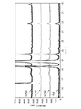
- the X-ray diffraction pattern shown in FIG. 1 contains 21% Al and 7% Mg, 0%, 0.2%, 0.4% or 0.6% Si, respectively, and the balance is Zn. And it is the X-ray diffraction measurement result of the surface of each plating layer which is an impurity. As shown in FIG. 1, it was confirmed that the X-ray diffraction peaks at 16.18 ° and 32.69 ° increased as the Si content increased, and Al 2 O as an Al—Si—O based compound was confirmed. The existence of 5 Si (JCPDS card No. 01-075-4827) can be recognized. Since the X-ray diffraction image changes depending on the X-ray irradiation conditions, the conditions for obtaining the X-ray diffraction image are as follows.
- X-rays targeting Cu are the most convenient because they can obtain average information on the constituent phases in the plating layer.
- the X-ray output conditions are a voltage of 40 kV and a current of 150 mA.
- the X-ray diffractometer is not particularly limited, and for example, a sample horizontal strong X-ray diffractometer RINT-TTR III manufactured by Rigaku Co., Ltd. can be used.
- a goniometer TTR horizontal goniometer
- the slit width of the K ⁇ filter was 0.05 mm
- the longitudinal limiting slit was 2 mm
- the light receiving slit was 8 mm
- the light receiving slit 2 was opened.
- Scan speed is 5 deg. It is preferable that / min is set, the step width is 0.01 deg, and the scan axis 2 ⁇ is 5 to 90 °.
- the diffraction intensity differs depending on the model, it is better to judge the presence or absence based on the relative intensity with respect to a specific angle. Specifically, as illustrated in FIG. 1, in the plating layer according to the present embodiment, no diffraction peak is observed near the diffraction angle of 27.0 °, so that the diffraction intensity (cps) at 27.0 ° is relative to the diffraction intensity (cps) at 27.0 °.
- the ratio of the total value of the diffraction peak intensity of 16.18 ° and the diffraction peak intensity (cps) of 32.69 ° is used as the evaluation parameter. That is, in the present embodiment, the diffraction intensity ratio R1 defined by the formula 4 needs to satisfy the formula 5.
- Equation 4 I (27.0 °) in Equation 4 is set to 585 cps. That is, it is as shown in Equation 4-1.
- the value of 585 cps used instead is the average value of the measurement data (actual value) of the diffraction intensity of the plating layer according to the present embodiment, and corresponds to the background intensity.
- the Al—Si—O compound represented by Al 2 O 5 Si is present in the plating layer.
- the diffraction intensity R1 is more than 10
- the Al—Si—O compound is sufficiently contained in the plating layer, and the appearance change of the plating layer over a long period of time can be significantly suppressed.
- the upper limit of the diffraction intensity ratio R1 does not need to be set in particular, but R1 may be 20 or less, 15 or less, or 12 or less.
- the plating layer according to this embodiment may contain Mg 2 Si.
- Mg 2 Si The existence of Mg 2 Si can be confirmed by X-ray diffraction.
- the JCPDS card No. In 00-035-0773 diffraction peaks at diffraction angles of 24.24 ° ((111) plane) and 28.07 ° ((200) plane) are known as the diffraction intensities of Mg 2 Si, and the surface of the plating layer is known.
- the presence of Mg 2 Si can be recognized by detecting these diffraction peaks on the X-ray diffraction pattern.
- the diffraction intensity R2 represented by the formula 6 satisfies the formula 7.
- the diffraction peak intensity of 24.24 ° and 28.07 with respect to the diffraction intensity (cps) at 27.0 °.
- the ratio of the total value of the diffraction peak intensities (cps) of ° is used as an evaluation parameter.
- the conditions for X-ray diffraction measurement when determining the diffraction intensity ratio R2 are the same as when determining the diffraction intensity ratio R1.
- the diffraction intensity ratio R2 By setting the diffraction intensity ratio R2 to more than 2.5, Mg 2 Si can be sufficiently contained in the plating layer, and blackening of the plating layer can be suppressed. However, when Mg 2 Si increases and the diffraction intensity ratio R2 increases, Al—Si—O-based compounds may decrease and affect the appearance change of the plating layer, and Zn—Al in the plating layer may be affected. -MgZn 2 The ternary eutectic structure may be reduced and the corrosion resistance of the plating layer may be lowered. Therefore, the diffraction intensity ratio R2 may be 20 or less, 15 or less, or 12 or less.
- the plated steel material of the present embodiment includes a steel material and a plating layer formed on the surface of the steel material.
- Zn-Al-Mg-based plating is formed by metal deposition and solidification reaction.
- the easiest means for forming a plating layer is to form a plating layer on the surface of a steel sheet by a hot-dip plating method, and it can be formed by a Zenzimer method, a flux method, or the like.
- the plated steel material of the present embodiment may be subjected to a vapor deposition plating method or a method for forming a plating film by thermal spraying, and the same effect as when formed by the hot-dip plating method can be obtained.
- the plated steel material of the present embodiment can be manufactured by either an immersion type plating method (batch type) or a continuous type plating method.
- the size, shape, surface morphology, etc. of the steel material to be plated there are no particular restrictions on the size, shape, surface morphology, etc. of the steel material to be plated. Ordinary steel, stainless steel, etc. can be applied as long as they are steel. Steel strips of general structural steel are most preferable. The surface may be finished by shot blasting in advance, and there is no problem even if a metal film or alloy film of 3 g / m 2 or less such as Ni, Fe, Zn plating is attached to the surface and then plated. do not have. Further, as a pretreatment of the steel material, it is preferable to sufficiently wash the steel material by degreasing and pickling.
- the steel material After sufficiently heating and reducing the surface of the steel sheet with a reducing gas such as H2 , the steel material is immersed in a plating bath prepared with a predetermined component.
- a reducing gas such as H2
- the components of the plating layer can be controlled by the components of the plating bath to be built.
- an alloy of the components of the plating bath is prepared by mixing a predetermined amount of pure metal, for example, by a melting method in an inert atmosphere. Since the component composition of the plating bath and the component composition of the plating layer are substantially the same, the component composition of the plating bath may be adjusted to the component composition of the plating layer described above.
- a plating layer having almost the same composition as the plating bath is formed. If the immersion time is long or it takes a long time to complete solidification, the formation of the interfacial alloy layer becomes active and the Fe concentration may increase. However, if the bath temperature of the plating bath is less than 500 ° C. Since the reaction with the plating layer is rapidly slowed down, the Fe concentration contained in the plating layer is usually less than 5.0%.
- the hot-dip plating layer it is preferable to immerse the reduced steel material in a plating bath at 500 ° C. to 650 ° C. for several seconds.
- Fe diffuses into the plating bath and reacts with the plating bath to form an intermetallic alloy layer (mainly an Al—Fe-based intermetallic compound layer) at the interface between the plating layer and the steel sheet.
- the interfacial alloy layer metal-chemically bonds the steel material below the interfacial alloy layer and the plating layer above.
- the steel material After immersing the steel material in the plating bath for a predetermined time, the steel material is pulled up from the plating bath, and N2 wiping is performed when the metal adhering to the surface is in a molten state to adjust the plating layer to a predetermined thickness.
- the thickness of the plating layer is preferably adjusted to 3 to 80 ⁇ m. When converted to the amount of adhesion of the plating layer, it is 10 to 500 g / m 2 (one side). Further, the thickness of the plating layer may be adjusted to 5 to 70 ⁇ m. When converted to the amount of adhesion, it is 20 to 400 g / m 2 (one side).
- the adhered molten metal is solidified.
- the cooling means at the time of plating solidification may be performed by spraying nitrogen, air or a hydrogen / helium mixed gas, mist cooling, or submersion in water. Mist cooling is preferable, and mist cooling in which water is contained in nitrogen is preferable.
- the cooling rate may be adjusted according to the water content.
- Al—Si—O it is necessary to strictly control the oxygen concentration and temperature range after immersion in the plating bath.
- the plating composition according to the present embodiment it is very easy to combine with oxygen, and if the oxygen concentration and the cooling rate are not controlled in an appropriate temperature range, a cloudy oxide film is formed on the surface of the plating layer, resulting in poor appearance.
- the formation of Al—Si—O becomes unstable, and the desired plating layer cannot be obtained. Therefore, in this embodiment, it is desirable to adopt the following manufacturing conditions.
- the oxygen concentration should not be in a low concentration state, and it is preferable to place the plating bath in the atmosphere. Therefore, the steel material is allowed to pass through the atmosphere from the time when the steel material is immersed in the plating bath until immediately after the steel material is pulled out from the plating bath. That is, the steel material immediately after being pulled up from the plating bath needs to be brought into contact with the atmosphere.
- the temperature of the molten metal adhering to the surface of the steel material is in the range of 490 to 400 ° C.
- the oxygen concentration in the atmosphere between 490 and 400 ° C. is set to less than 3000 ppm. More preferably, the oxygen concentration in the atmosphere between 490 and 400 ° C. is less than 2000 ppm, more preferably less than 1000 ppm.
- the plating bath temperature needs to be maintained at more than 490 ° C., preferably 500 ° C. or higher.
- the oxygen concentration in the atmosphere between the plating bath temperature and 490 ° C. is preferably 3000 ppm or more.
- the average cooling rate between the bath temperature and 400 ° C. is less than 15 ° C./sec.
- the average cooling rate up to 400 ° C. should always be less than 15 ° C./sec.
- the oxygen concentration from immediately after the steel material is pulled up from the plating bath to 400 ° C. and the average cooling rate are controlled as described above, and the temperature of the plating layer is 400 to 300 ° C.
- a plating layer containing an Al—Si—O-based compound is formed on the surface of the steel material.
- the conditions in the temperature range of less than 300 ° C. need not be particularly limited. As described above, the plating layer according to the present embodiment is formed.
- the production temperature range and the respective element concentrations determine the formation behavior of this compound because of the ease of movement of the elements. Further, since the composition of the plating layer and the production temperature range are limited to a predetermined range, it is considered that excessive precipitation of Mg 2 Si is suppressed.
- various chemical conversion treatments and coating treatments may be performed on the plating layer. It is also possible to use the uneven pattern on the surface of the plating layer, further add a plating layer such as Cr, Ni, and Au, and further paint to give a design. Further, in order to further enhance the corrosion resistance, repair touch-up paint, thermal spraying treatment, etc. may be performed on the welded portion, the processed portion, and the like.
- the plated steel material of the present embodiment may have a film formed on the plated layer.
- the film can form one layer or two or more layers.
- Examples of the type of film immediately above the plating layer include a chromate film, a phosphate film, and a chromate-free film. Chromate treatment, phosphate treatment, and chromate-free treatment for forming these films can be performed by known methods.
- Chromate treatment includes electrolytic chromate treatment that forms a chromate film by electrolysis, reactive chromate treatment that forms a film using the reaction with the material, and then rinses away excess treatment liquid, and the treatment liquid is applied to the object to be coated.
- electrolytic chromate treatment electrolysis using chromic acid, silica sol, resin (phosphoric acid, acrylic resin, vinyl ester resin, vinyl acetate acrylic emulsion, carboxylated styrene butadiene latex, diisopropanolamine modified epoxy resin, etc.), and hard silica.
- Chromate treatment can be exemplified.
- Examples of the phosphate treatment include zinc phosphate treatment, zinc phosphate calcium treatment, and manganese phosphate treatment.
- Chromate-free treatment is particularly suitable without burdening the environment.
- Chromate-free treatment includes electrolytic chromate-free treatment that forms a chromate-free film by electrolysis, reactive chromate-free treatment that forms a film using the reaction with the material, and then rinses away excess treatment liquid.
- organic resin films may be provided on the film directly above the plating layer.
- the organic resin is not limited to a specific type, and examples thereof include polyester resin, polyurethane resin, epoxy resin, acrylic resin, polyolefin resin, and modified products of these resins.
- the modified product is obtained by reacting a reactive functional group contained in the structure of these resins with another compound (monomer, cross-linking agent, etc.) containing a functional group capable of reacting with the functional group. Refers to resin.
- organic resin one kind or two or more kinds of organic resins (not modified) may be mixed and used, or at least one kind of others in the presence of at least one kind of organic resin.
- the organic resin obtained by modifying the organic resin of the above may be used alone or in combination of two or more.
- the organic resin film may contain any coloring pigment or rust preventive pigment.
- Water-based products can also be used by dissolving or dispersing in water.
- the basic corrosion resistance of the plated steel sheet may be evaluated by an exposure test, a salt spray test (JIS Z2371), a composite cycle corrosion test (CCT) including a salt spray test, or the like to evaluate the corrosion resistance of the bare flat surface portion.
- a salt spray test JIS Z2371
- CCT composite cycle corrosion test
- one of these tests is carried out with the plated steel sheet open at the cut end face, and the red rust area ratio of the end face (the smaller the better, the better the corrosion resistance) is evaluated. By doing so, the superiority or inferiority of sacrificial anticorrosion can be evaluated.
- the change in plating appearance by the change in color difference after the corrosion test. For example, since the initial appearance change is expected to be corroded by humidity, the color difference before and after being left in the constant temperature and humidity chamber is observed. Using a color difference meter, color determination is performed based on the absolute value of ⁇ E for the change in the L * a * b * color space. If ⁇ E is small, it means that the color change is small before and after corrosion, and conversely, if it is large, it means that the color change is large before and after corrosion. When investigating long-term corrosion, the color difference before and after the salt spray test and the composite cycle corrosion test may be determined.
- ⁇ E is expressed by the following formula when the chromaticity index in the L * a * b * color system is a * and b * and the brightness index is L * .
- ⁇ E * ab ⁇ (( ⁇ a * ) 2 + ( ⁇ b * ) 2 + ( ⁇ L * ) 2 )
- the plated steel materials (plated steel sheets) shown in Tables 2A to 6B were manufactured and their performance was evaluated.
- pure metal was mixed and the bath was built.
- Fe powder was added to the components of the plating alloy to prevent the Fe concentration from increasing during the test.
- the plating layer was peeled off with hydrochloric acid in which the inhibitor was dissolved, and the component analysis of the peeled components was carried out by ICP. “0” in the table indicates that the content of the element was below the detection limit.
- a 180 ⁇ 100 size hot-rolled original plate (1.6 to 3.2 mm) was tested for a plated steel sheet using a batch hot-dip plating simulator (manufactured by Reska).
- a K thermocouple is attached to a part of the original plating plate, and after annealing for 1 minute at an annealing temperature of 800 ° C. in an N 2 (H 2-5 % reduction) atmosphere, the surface of the original plating plate is sufficiently reduced with hydrogen, and each It was immersed in the plating bath under the conditions for 3 seconds. After that, the plated steel sheet was pulled up and the plating thickness was adjusted to 25 to 30 ⁇ m by N2 gas wiping. Further, after the plated steel sheet was pulled up from the plating bath, the plated steel sheet was manufactured under various cooling conditions A to K in Table 1.
- Condition D is a comparative condition in which the oxygen concentration between the bath temperature and 490 ° C. is low.
- Condition E is a comparative condition in which the oxygen concentration between 400 and 300 ° C. is low.
- Condition F is a comparative condition in which the oxygen concentration between the bath temperature and 490 ° C. and the oxygen concentration between 400 and 300 ° C. are low.
- Condition G is a comparative condition in which the average cooling rate between the bath temperature and 400 ° C. is high.
- Condition H is a comparative condition in which the average cooling rate between 400 and 300 ° C. is low.
- Condition K is a comparative condition in which the oxygen concentration between 490 and 400 ° C. is high. Other conditions are preferable conditions.
- the plated steel plate after plating is cut into 20 mm squares, and an X-ray output 40 kV, 150 mA, copper target, goniometer TTR (horizontal goniometer), using a high-angle X-ray diffractometer (manufactured by Rigaku, model number RINT-TTR III),
- a high-angle X-ray diffractometer manufactured by Rigaku, model number RINT-TTR III
- a square test piece with a size of 70 x 150 mm was cut out from the manufactured plated steel sheet, and the end face of the test piece was protected with an epoxy resin paint to perform a 5% salt spray test (JIS). 2371) was carried out for 120 hours to evaluate the white rust area ratio on the evaluation surface.
- JIS 5% salt spray test
- a white rust area ratio of less than 5% is defined as "AAA”.
- a white rust area ratio of 5 to 10% is defined as “AA”.
- a white rust area ratio of 10 to 20% is defined as “A”.
- Those having a white rust area ratio of 20% or more are designated as "B”.
- a 70 x 150 mm square test piece was cut out from the plated steel plate, and the JASO test (M609-91) was carried out with the four end faces of the test piece open.
- the red rust area ratio of the part was evaluated.
- the evaluation criteria for the red rust area ratio are shown below. "A" and above were accepted.
- a red rust area ratio of less than 5% is defined as "AAA”.
- a red rust area ratio of 5 to 10% is defined as “AA”.
- a red rust area ratio of 10 to 20% is defined as “A”.
- Those having a red rust area ratio of 20% or more are designated as "B”.
- Corrosion appearance evaluation is to cut out a square test piece with a size of 70 x 150 mm from the manufactured plated steel sheet, protect the end face with epoxy resin paint, and keep the plated steel sheet at a constant temperature of 90% humidity and 70 degrees Celsius. The mixture was left in a constant humidity bath for 24, 48, 72, and 120 hours, and the color difference before and after the test was measured. The change in the appearance of the steel sheet was evaluated based on the amount of change in ⁇ E (SCE method). The evaluation criteria are as follows. "A" and above were accepted.
- ⁇ E is expressed by the following formula when the chromaticity index in the L * a * b * color system is a * and b * and the brightness index is L * . "A" and above were accepted.
- ⁇ E * ab ⁇ (( ⁇ a * ) 2 + ( ⁇ b * ) 2 + ( ⁇ L * ) 2 )
- ⁇ E ⁇ 5 When ⁇ E ⁇ 5 is continued for 120 hours or more, it is defined as “S”. Those in which ⁇ E ⁇ 5 continues for 72 hours or more are referred to as “AAA”. Those in which ⁇ E ⁇ 5 continues for 48 hours or more are defined as “AA”. When ⁇ E ⁇ 5 is continued for 24 hours or more, it is defined as “A”. If ⁇ E ⁇ 5 does not continue within 24 hours, it is defined as "B”.
- ⁇ E ⁇ 5 When ⁇ E ⁇ 5 is continued for 15 cycles or more, it is defined as “S”. Those in which ⁇ E ⁇ 5 is continued for 9 cycles or more are defined as “AAA”. Those in which ⁇ E ⁇ 5 is continued for 6 cycles or more are defined as “AA”. When ⁇ E ⁇ 5 is continued for 3 cycles or more, it is defined as “A”. If ⁇ E ⁇ 5 does not continue within 3 cycles, it is defined as "B”.
- Examples 1 to 5, 11, 12, 14 to 16, 21, 22, 26 to 46, and 48 to 51 satisfy the scope of the present invention, and have corrosion resistance and sacrificial corrosion protection.
- the properties, corrosive appearance evaluation (short-term) and corrosive appearance evaluation (long-term) were all good.
- Comparative examples 6 to 10, 13, 17 to 21 and 24 had a diffraction intensity ratio R1 of 2.5 or less because the production conditions were not preferable, and corrosion resistance, sacrificial corrosion resistance, corrosion appearance evaluation (short term) and corrosion appearance evaluation (short term) and None of the characteristics of the corrosion appearance evaluation (long-term) were satisfactory.
- Comparative Example 25 (Si / ⁇ B) ⁇ (Mg / Si) was 375.0 or more, whereby the diffraction intensity ratio R1 was 2.5 or less, and corrosion resistance, sacrificial corrosion resistance, corrosion appearance evaluation (short term) and corrosion appearance evaluation (short term) and None of the characteristics of the corrosion appearance evaluation (long-term) were satisfactory.
- the present invention since it is possible to provide a Zn-based plated steel material having little change in appearance over a particularly long period of time, the present invention has high industrial applicability.
Abstract
Description
本願は、2021年1月18日に日本に出願された特願2021-005575号に基づき優先権を主張し、その内容をここに援用する。
[1] 鋼材表面に、めっき層を有するめっき鋼材であって、
前記めっき層の平均化学組成が、質量%で、
Zn:50.00%超、
Al:15.0%超30.0%未満、
Mg:5.0%超15.0%未満、
Si:0.25%以上3.50%未満、
Sn:0%以上1.00%未満、
Bi:0%以上1.00%未満、
In:0%以上1.00%未満、
Ca:0%以上0.60%未満、
Y :0%以上0.60%未満、
La:0%以上0.60%未満、
Ce:0%以上0.60%未満、
Sr:0%以上0.60%未満、
Cr:0%以上0.25%未満、
Ti:0%以上0.25%未満、
Ni:0%以上0.25%未満、
Co:0%以上0.25%未満、
V :0%以上0.25%未満、
Nb:0%以上0.25%未満、
Zr:0%以上0.25%未満、
Mo:0%以上0.25%未満、
W:0%以上0.25%未満、
Ag:0%以上0.25%未満、
Cu:0%以上0.25%未満、
Mn:0%以上0.25%未満、
Fe:0%以上5.0%未満、
Sb:0%以上0.5%以下、
Pb:0%以上0.5%以下、
B :0%以上0.5%以下、
P :0%以上0.5%以下、
及び、不純物からなり、
Sn、Bi及びInからなる群から選択される少なくとも1種の合計量(ΣA)が1.00%未満であり、
Ca、Y、La、Ce及びSrからなる群から選択される少なくとも1種の合計量(ΣB)が0.02%以上0.60%未満であり、
Mgの含有量、Siの含有量及び前記ΣBが、下記式1~式3を満たし、
Cu-Kα線を使用し、X線出力が40kV及び150mAである条件で測定した、前記めっき層表面のX線回折パターンにおいて、下記式4で定義される回折強度比R1が、下記式5を満たす、めっき鋼材。
2.0≦Mg/Si<20.0 …式1
3.0≦Si/ΣB<24.0…式2
26.0≦(Si/ΣB)×(Mg/Si)<375.0…式3
R1={I(16.18°)+I(32.69°)}/I(27.0°) …式4
2.5<R1…式5
ただし、式1~式3におけるSi及びMgは前記めっき層のSi及びMgの平均組成(質量%)であり、式4におけるI(16.18°)は前記X線回折パターンの2θ=16.18°における回折強度(cps)であり、I(32.69°)は前記X線回折パターンの2θ=32.69°における回折強度(cps)であり、I(27.0°)は前記X線回折パターンの2θ=27.0°における回折強度(cps)である。なお、2θ=27.0°において1000cps以上の強度の回折ピークが現れる場合は、式4におけるI(27.0°)を、585cpsとする。
[2] Cu-Kα線を使用し、X線出力が40kV及び150mAである条件で測定した、前記めっき層表面のX線回折パターンにおいて、下記式6で定義される回折強度比R2が、下記式7を満たす、[1]に記載のめっき鋼材。
R2={I(24.24°)+I(28.07°)}/I(27.0°) …式6
2.5<R2…式7
ただし、式6におけるI(24.24°)は前記X線回折パターンの2θ=24.24°における回折強度(cps)であり、I(28.07°)は前記X線回折パターンの2θ=28.07°における回折強度(cps)であり、I(27.0°)は前記X線回折パターンの2θ=27.0°における回折強度(cps)である。なお、2θ=27.0°において1000cps以上の強度の回折ピークが現れる場合は、式6におけるI(27.0°)を、585cpsとする。
[3] 前記式4で定義される前記R1が下記式8を満たす、[1]または[2]に記載のめっき鋼材。
10<R1 …式8
[4] 下記式9を満たす、[1]から[3]の何れか一項に記載のめっき鋼材。
3.0≦Si/ΣA<50.0 …式9
ただし、式9におけるSiは前記めっき層のSiの平均組成(質量%)である。
以下、本発明の実施形態のめっき鋼材について説明する。
3.0≦Si/ΣB<24.0…式2
26.0≦(Si/ΣB)×(Mg/Si)<375.0…式3
R1={I(16.18°)+I(32.69°)}/I(27.0°) …式4
2.5<R1…式5
また、「~」を用いて表される数値範囲は、「~」の前後に記載される数値を下限値及び上限値として含む範囲を意味する。
鋼材の形状には、特に制限はない、鋼材は、鋼板の他、鋼管、土木・建築材(柵渠、コルゲートパイプ、排水溝蓋、飛砂防止板、ボルト、金網、ガードレール、止水壁等)、プレハブ用部材、住宅壁、屋根材、家電部材(エアコンの室外機の筐体等)、自動車外板、自動車部品(足回り部材等)などであってもよく、溶接に供され成形された鋼構造部材の材料であってもよい。
本実施形態に係るめっき鋼材は、汎用性の高いZn系めっき鋼材であり、犠牲防食性を確保する目的で一定量以上のZnを含有させる。これにより、鋼材に適切な犠牲防食性を付与する。例えば、1.6mm以上の切断端面が開放されるような環境でも、Zn量が50.00%を超えていれば、切断端面部に十分な犠牲防食性作用が現れ、高い耐食性を維持できる。Zn含有量が50.00%以下の場合は、切断端面が開放される場合など、めっき層の厚みによって耐食性が劣位になる場合がある。従って、Zn含有量は50.00%超とする。好ましくは、Zn含有量は、65.00%以上、より好ましくは70.00%超である。Zn含有量の上限は特に限定する必要はないが、Zn含有量が高すぎると、他の合金元素の含有量が相対的に低下するため、例えば80.00%以下としてもよい。
Alは、Znと同様に、めっき層の主体を構成する元素である。Zn-Al-Mg系めっきでは、Alはめっき層中で主にAl相を形成する。Al相はめっき層表面にも存在し、Al相の周囲でAl2O3被膜を形成している。一方、本実施形態に係るめっき層中に含まれるAl相の量では、めっき層表面全体を覆うような酸化被膜を形成できない。すなわち、Al含有量が15.0%以下では、酸化被膜を形成する化合物であるAl-Si-O系化合物を形成するために十分なAl含有量に達せず、めっき層中においてAl-Si-O系化合物を検出できなくなる。一方、Al含有量が30.0%以上となると、前記のように、犠牲防食性が低下するため、Al含有量は30.0%未満とする。好ましいAl含有量は17.0%以上、20.0%以上、好ましいAl含有量は29.0%以下または25.0%以下である。
Mgは、犠牲防食効果があり、耐食性を高める元素である。本実施形態に係るめっき鋼材の高い耐食性、及び高い犠牲防食性は、Mgの含有によって達成される。Mgが不足すると犠牲防食効果が小さくなり、耐食性が低くなる傾向にあることから、その下限を5.0%超とする。一方、Mg含有量が15.0%以上では、めっき層中のAl含有量が相対的に低くなり、めっき層表層にAl相が形成されなくなり、酸化被膜が不安定になり、腐食時の外観が大きく劣化する。これは、Al相が相対的に減少する代わりに、MgZn2相がめっき層表層に多量に形成するためである。Al-Si-O系化合物も形成されなくなる。そのため、Mg含有量は15.0%未満とする。好ましいMg含有量は、5.1%以上、6.0%以上、好ましいMg含有量は、13.0%以下または12.5%以下である。
Siは、Al-Fe合金層の成長を抑制し、また、耐食性を向上させる。Siは、微量に含有する場合、Al-Ca-Si系化合物などを形成するほか、Al-Fe合金層にも侵入型固溶する。Al-Fe合金層でのAl-Fe-Si金属間化合物相の形成等の説明は、既に前述したとおりである。これらの化合物に取り込まれ得る場合は、めっき層としての性能に何ら性能変化を生み出すことがない。したがって、Siが0.25%未満では、これらの化合物にSiの多くが囚われてしまい、めっき層の外観変化や犠牲防食性、その他、耐食性などの性能に変化をもたらすことができない。従って、Siは0.25%以上とする。また、Siはその下限濃度を超えると、めっき層中にAl-Si-O系化合物を形成させる。このAl-Si-O系化合物は、めっき層中のAlに由来するAl2O3とともに強固な酸化被膜を形成して、めっき層の外観低下を抑制する。そこで、好ましくはSiの含有量は0.25%以上とし、好ましくはSiの含有量は0.50%以上、0.60%以上とする。
MgとSiは非常に化合しやすくMg2Siを形成するが、MgとSiの含有量の割合はめっき層の特性に大きな影響を及ぼすため、MgとSiの含有量の比率(Mg/Si)を適切な範囲にする必要がある。めっき層に含有するMgは、Mg2Siを形成する傾向にあるが、Mg/Siが過大になると(MgがSiに対して多すぎると)、犠牲防食性の向上に寄与するMg2Siが減少し形成しにくくなり、めっき層の犠牲防食性が低下するおそれがあり、また、Siが足りずに酸化被膜による効果も期待できなくなることからめっき層の外観変化が著しくなる。また、Mg/Siが過小になると、めっき層にAl-Si-O系化合物が多量に形成され、このAl-Si-O系化合物がめっき層表面に粒状に付着し、めっき層の外観を悪化させ、さらにはめっき層の耐食性も低下させる。またSiがめっき層の様々な他の添加元素と結合して、めっき層の性質を維持することも困難となる。従って、Mg/Siは、2.0以上とし、より好ましくは、6.0以上とし、さらに好ましくは、8.0以上とする。Mg/Siは、20.0未満とし、より好ましくは、16.0以下とし、さらに好ましくは、12.0以下とする。
元素群Aは、任意に含有できる元素(Sn、Bi、In)である。元素群Aから選択される元素の少なくとも1種を含有させると犠牲防食性が向上する。元素群Aの各元素は、めっき層中のMgとともに化合物を形成し、この化合物は水分等に溶出しやすくMgを簡単に溶出させるため、犠牲防食性を付与することができる。各元素は0.01%以上含有することにより、例えば1.6mmの板厚の切断端面部で犠牲防食性の改善効果が確認できる。ただし、これらの元素の過度の含有は、めっき層の犠牲防食性が向上する結果、めっき層がより溶出しやすくなり、平面部等の耐食性に悪影響を及ぼす。また、めっき層の外観が変化しやすくなる。従って、元素群Aの各元素の含有量はそれぞれ1.00%未満とする。元素群Aの合計量(ΣA)もまた、1.00%未満とする。ΣAが1.00%以上になると、めっき層が外観変化しやすくなる。
元素群Bの元素(Ca、Y、La、Ce、Sr)は、任意添加元素であり、元素群Bから選択される元素の少なくとも1種とMgとを共に含有することで、耐食性や犠牲防食性が僅かに向上する傾向にある。ただし、これらの元素が過剰に含まれると、各々の元素主体の金属間化合物相を形成し、めっき層が硬質化して、めっき層の加工時に割れを生じた後、パウダリング剥離を起こすおそれがある。従って、これらの元素の含有量はそれぞれ、0.60%未満とすることが好ましい。各元素の含有量は、0.01%以上としてもよく、0.02%以上としてもよい。
Si含有量と元素群Bに含まれる元素の合計量(ΣB)との割合(Si/ΣB)が24.0以上の場合(Siが多すぎて、元素群Bが少なすぎる場合)、めっき層中のMgは、粗大なMg2Siを形成する傾向にあり、Al-Si-O系化合物を十分に形成する程、Mg-Si間の結合反応を抑制できず、元素群BによるAl-Si-O系化合物を形成させる効果が得られない。あまりに粗大なMg2SiがAl-Si-O酸化物の効果も打ち消してしまう。このため、Al-Si-O系化合物による回折ピークが現れず、めっき層の外観変化を抑制する効果が得られなくなる。
式1及び式2の両方が満たされることで、Al-Si-O系化合物が形成する条件が整う。ただし、式1及び式2のそれぞれの上限値及び下限値の近傍は、めっき層のMg、Si、元素群B以外の他の構成元素の成分配合によっては、Al-Si-O系化合物の形成よりも、Mg2SiやAl-Ca-Si化合物の形成が優位になる場合がある。そのため、確実にAl-Si-O系化合物の形成を優位にするための条件として、(Si/ΣB)×(Mg/Si)を26.0以上375.0未満の範囲とする。(Si/ΣB)×(Mg/Si)は、式2におけるSi/ΣBと、式1におけるMg/Siとの積であり、安定的にAl-Si-O系化合物を得るには、この積の下限が26.0以上になる必要がある。この積が26.0未満では、Al-Si-O系化合物の形成が不安定になり、めっき層の外観維持や、耐食性向上など所定の性能が得られない場合がある。また上限についても、同様な理由から、375.0未満とする必要がある。より好ましくは、(Si/ΣB)×(Mg/Si)は、30.0以上であり、さらに好ましくは35.0以上である。より好ましくは、(Si/ΣB)×(Mg/Si)は、200.0以下であり、さらに好ましくは100.0以下である。
元素群Cにおける元素のうち、Feを除く元素は、めっき層に対して任意に含有可能な金属元素である。これらの元素(Cr、Ti、Ni、Co、V、Nb、Zr、Mo、W、Ag、Cu、Mn)が含有されることで、めっき層の平面部耐食性が向上する効果が現れる。0.10%以上の含有で耐食性が明瞭に改善する効果が確認されるため、好ましくはこれらの元素をそれぞれ0.10%以上含有させるとよい。これらの元素は、それぞれ0.25%未満の範囲で含有させる限り、Al-Si-O系化合物の形成に影響を与えないため、これらの元素の含有量はそれぞれ、Feを除き、0.25%未満とする。
元素群Dに含まれる元素(Sb、Pb、B、P)は、めっき層に添加可能な半金属元素である。これらの元素が含有されることで、めっき層の平面部耐食性が向上する効果が現れる。0.1%以上の含有で耐食性が明瞭に改善する効果が確認されるため、好ましくはこれらの元素をそれぞれ0.1%以上含有させるとよい。これらの元素は、それぞれ0.5%以下の範囲で含有させる限り、Al-Si-O系化合物の形成に影響を与えないため、これらの元素の含有量はそれぞれ0.5%以下とする。
不純物は、原材料に含まれる成分、または、製造の工程で混入する成分であって、意図的に含有させたものではない成分を指す。例えば、めっき層には、鋼材(地鉄)とめっき浴との相互の原子拡散によって、不純物として、Fe以外の成分も微量混入することがある。また、不純物には酸素が含まれる。本実施形態に係るめっき層は、その製造工程においてめっき浴から引き上げた際に溶融状態のめっき層が酸素に触れることにより、不純物レベルの少量の酸素が含まれるようになる。この不純物レベルの酸素により、Al-Si-O系化合物が形成されるようになる。めっき層に酸素が含有されることは、EPMA等によるめっき層断面組織の酸素の定量分析を実施することによって確認できる。
元素群Aは、Mg2Siと同じように犠牲防食性に大きな作用を与える化合物を形成することや、Mgと非常に化合しやすいため、結果としてSiの効果を変えうることから、元素群Aの合計量(ΣA)とSiとの比率(Si/ΣA)は適切な範囲にすることが好ましい。添加量を制御することで、Siの効果を最大現に発揮でき、性能の優れためっき層へ変化させることができる。Si/ΣAが3.0以上50.0未満であることで、犠牲防食性に優れためっき層を得ることができ、例えば、切断端面部やめっき加工部等において優れた犠牲防食性を確保しつつ、外観変化に強いめっき層を作成することができる。Si/ΣAが3.0未満となると、犠牲防食効果が強すぎて、外観変化しやすくなる場合がある。また、Si/ΣAが50.0以上となると、犠牲防食性の向上効果が見込めなくなる。より好ましいSi/ΣAの範囲は3.0以上である。より好ましいSi/ΣAの範囲は10.0以下であり、さらに好ましくは、7.0以下である。
2.5<R1…式5
2.5<R2…式7
本実施形態のめっき鋼材は、鋼材と、鋼材の表面に形成されためっき層とを備える。通常、Zn-Al-Mg系めっきは、金属の堆積と凝固反応によって形成させる。最もめっき層を形成するのに容易な手段は、溶融めっき方法により、鋼板表面にめっき層を形成させることであり、ゼンジマー法やフラックス法などによって形成することが可能である。また、本実施形態のめっき鋼材は、蒸着めっき法や、溶射によるめっき皮膜の形成法を適用してもよく、溶融めっき法で形成した場合と同様の効果を得ることができる。
また、犠牲防食性を確認するためには、めっき鋼板を切断端面開放の状態で、これらいずれかの試験を実施し、端面部の赤錆面積率(小さいもの程、耐食性が優れている)を評価することで、犠牲防食性の優劣を評価できる。
各種、めっき浴の調合には純金属を調合して建浴した。めっき合金の成分は建浴後、Fe粉を足して、試験中におけるFe濃度の上昇がないようにした。めっき鋼板の成分については、インヒビターを溶かした、塩酸にてめっき層を剥離し、ICPにて、剥離成分の成分分析を実施した。表中の「0」は、当該元素の含有量が検出限界未満であったことを示す。

条件Eは、400~300℃の間の酸素濃度が低い、比較条件である。
条件Fは、浴温から490℃の間の酸素濃度と、400~300℃の間の酸素濃度が低い、比較条件である。
条件Gは、浴温から400℃の間の平均冷却速度が高い、比較条件である。
条件Hは、400~300℃の間の平均冷却速度が低い、比較条件である。
条件Kは、490~400℃の間の酸素濃度が高い、比較条件である。
これ以外の条件は、好ましい条件である。
白錆面積率が5~10%を「AA」とする。
白錆面積率が10~20%を「A」とする。
白錆面積率が20%以上のものを「B」とする。
赤錆面積率が5~10%を「AA」とする。
赤錆面積率が10~20%を「A」とする。
赤錆面積率が20%以上のものを「B」とする。
ΔE<5未満が72時間以上継続したものを「AAA」とする。
ΔE<5未満が48時間以上継続したものを「AA」とする。
ΔE<5未満が24時間以上継続したものを「A」とする。
ΔE<5未満が24時間以内で継続しなかったものを「B」とする。
ΔE<5未満が9サイクル以上継続したものを「AAA」とする。
ΔE<5未満が6サイクル以上継続したものを「AA」とする。
ΔE<5未満が3サイクル以上継続したものを「A」とする。
ΔE<5未満が3サイクル以内で継続しなかったものを「B」とする。
比較例25は、(Si/ΣB)×(Mg/Si)が375.0以上になり、これにより回折強度比R1が2.5以下となり、耐食性、犠牲防食性、腐食外観評価(短期)及び腐食外観評価(長期)の各特性がいずれも満足できるものではなかった。
比較例47は、(Si/ΣB)×(Mg/Si)が26.0未満になり、これにより回折強度比R1が2.5以下となり、耐食性、犠牲防食性、腐食外観評価(短期)及び腐食外観評価(長期)の各特性がいずれも満足できるものではなかった。
比較例52~78は、めっき層の平均化学組成が本発明の範囲から外れており、これにより回折強度比R1が2.5以下となり、耐食性、犠牲防食性、腐食外観評価(短期)及び腐食外観評価(長期)の各特性がいずれも満足できるものではなかった。

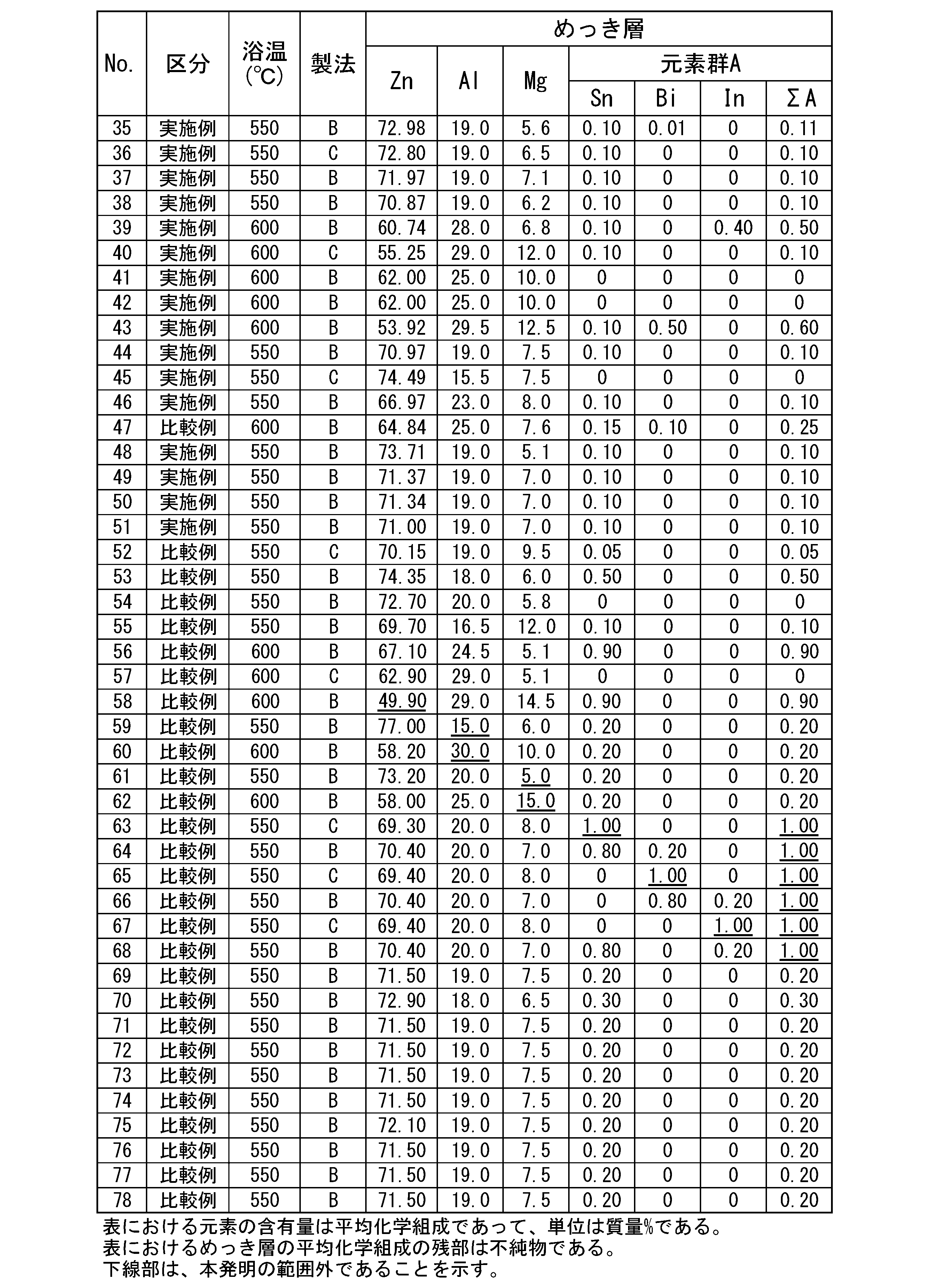

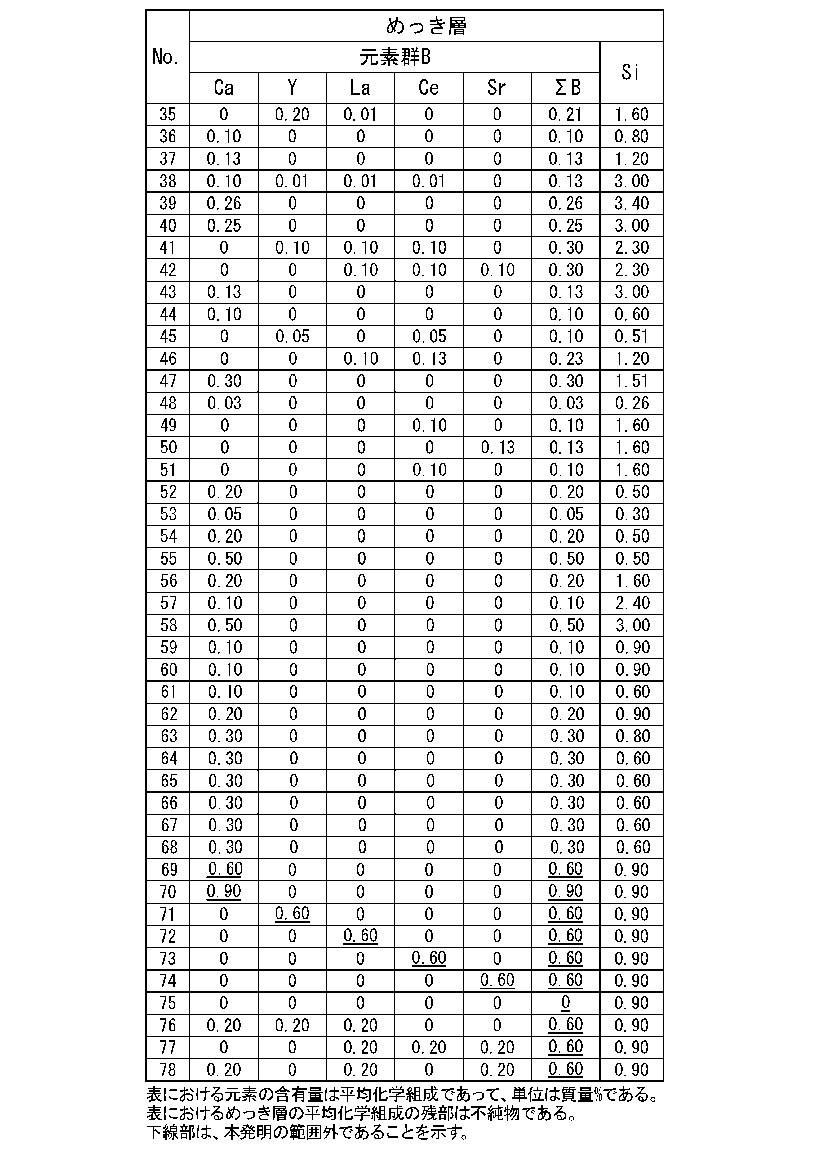


Claims (4)
- 鋼材表面に、めっき層を有するめっき鋼材であって、
前記めっき層の平均化学組成が、質量%で、
Zn:50.00%超、
Al:15.0%超30.0%未満、
Mg:5.0%超15.0%未満、
Si:0.25%以上3.50%未満、
Sn:0%以上1.00%未満、
Bi:0%以上1.00%未満、
In:0%以上1.00%未満、
Ca:0%以上0.60%未満、
Y :0%以上0.60%未満、
La:0%以上0.60%未満、
Ce:0%以上0.60%未満、
Sr:0%以上0.60%未満、
Cr:0%以上0.25%未満、
Ti:0%以上0.25%未満、
Ni:0%以上0.25%未満、
Co:0%以上0.25%未満、
V :0%以上0.25%未満、
Nb:0%以上0.25%未満、
Zr:0%以上0.25%未満、
Mo:0%以上0.25%未満、
W:0%以上0.25%未満、
Ag:0%以上0.25%未満、
Cu:0%以上0.25%未満、
Mn:0%以上0.25%未満、
Fe:0%以上5.0%未満、
Sb:0%以上0.5%以下、
Pb:0%以上0.5%以下、
B :0%以上0.5%以下、
P :0%以上0.5%以下、
及び、不純物からなり、
Sn、Bi及びInからなる群から選択される少なくとも1種の合計量(ΣA)が1.00%未満であり、
Ca、Y、La、Ce及びSrからなる群から選択される少なくとも1種の合計量(ΣB)が0.02%以上0.60%未満であり、
Mgの含有量、Siの含有量及び前記ΣBが、下記式1~式3を満たし、
Cu-Kα線を使用し、X線出力が40kV及び150mAである条件で測定した、前記めっき層表面のX線回折パターンにおいて、下記式4で定義される回折強度比R1が、下記式5を満たす、めっき鋼材。
2.0≦Mg/Si<20.0 …式1
3.0≦Si/ΣB<24.0…式2
26.0≦(Si/ΣB)×(Mg/Si)<375.0…式3
R1={I(16.18°)+I(32.69°)}/I(27.0°) …式4
2.5<R1…式5
ただし、式1~式3におけるSi及びMgは前記めっき層のSi及びMgの平均組成(質量%)であり、式4におけるI(16.18°)は前記X線回折パターンの2θ=16.18°における回折強度(cps)であり、I(32.69°)は前記X線回折パターンの2θ=32.69°における回折強度(cps)であり、I(27.0°)は前記X線回折パターンの2θ=27.0°における回折強度(cps)である。なお、2θ=27.0°において1000cps以上の強度の回折ピークが現れる場合は、式4におけるI(27.0°)を、585cpsとする。 - Cu-Kα線を使用し、X線出力が40kV及び150mAである条件で測定した、前記めっき層表面のX線回折パターンにおいて、下記式6で定義される回折強度比R2が、下記式7を満たす、請求項1に記載のめっき鋼材。
R2={I(24.24°)+I(28.07°)}/I(27.0°) …式6
2.5<R2…式7
ただし、式6におけるI(24.24°)は前記X線回折パターンの2θ=24.24°における回折強度(cps)であり、I(28.07°)は前記X線回折パターンの2θ=28.07°における回折強度(cps)であり、I(27.0°)は前記X線回折パターンの2θ=27.0°における回折強度(cps)である。なお、2θ=27.0°において1000cps以上の強度の回折ピークが現れる場合は、式6におけるI(27.0°)を、585cpsとする。 - 前記式4で定義される前記R1が下記式8を満たす、請求項1または請求項2に記載のめっき鋼材。
10<R1 …式8 - 下記式9を満たす、請求項1から請求項3の何れか一項に記載のめっき鋼材。
3.0≦Si/ΣA<50.0 …式9
ただし、式9におけるSiは前記めっき層のSiの平均組成(質量%)である。
Priority Applications (8)
| Application Number | Priority Date | Filing Date | Title |
|---|---|---|---|
| JP2022520416A JP7156573B1 (ja) | 2021-01-18 | 2021-11-30 | めっき鋼材 |
| EP21919583.1A EP4279629A1 (en) | 2021-01-18 | 2021-11-30 | Plated steel material |
| CN202180090264.9A CN116685706B (zh) | 2021-01-18 | 2021-11-30 | 镀覆钢材 |
| AU2021418839A AU2021418839A1 (en) | 2021-01-18 | 2021-11-30 | Plated steel material |
| US18/271,990 US20240043980A1 (en) | 2021-01-18 | 2021-11-30 | Plated steel material |
| KR1020237024692A KR102639488B1 (ko) | 2021-01-18 | 2021-11-30 | 도금 강재 |
| CA3203490A CA3203490A1 (en) | 2021-01-18 | 2021-11-30 | Plated steel material |
| CONC2023/0009029A CO2023009029A2 (es) | 2021-01-18 | 2023-07-06 | Material de acero enchapado |
Applications Claiming Priority (2)
| Application Number | Priority Date | Filing Date | Title |
|---|---|---|---|
| JP2021-005575 | 2021-01-18 | ||
| JP2021005575 | 2021-01-18 |
Publications (1)
| Publication Number | Publication Date |
|---|---|
| WO2022153694A1 true WO2022153694A1 (ja) | 2022-07-21 |
Family
ID=82447128
Family Applications (1)
| Application Number | Title | Priority Date | Filing Date |
|---|---|---|---|
| PCT/JP2021/043848 WO2022153694A1 (ja) | 2021-01-18 | 2021-11-30 | めっき鋼材 |
Country Status (11)
| Country | Link |
|---|---|
| US (1) | US20240043980A1 (ja) |
| EP (1) | EP4279629A1 (ja) |
| JP (1) | JP7156573B1 (ja) |
| KR (1) | KR102639488B1 (ja) |
| CN (1) | CN116685706B (ja) |
| AU (1) | AU2021418839A1 (ja) |
| CA (1) | CA3203490A1 (ja) |
| CL (1) | CL2023002002A1 (ja) |
| CO (1) | CO2023009029A2 (ja) |
| TW (1) | TWI807512B (ja) |
| WO (1) | WO2022153694A1 (ja) |
Families Citing this family (1)
| Publication number | Priority date | Publication date | Assignee | Title |
|---|---|---|---|---|
| TWI826270B (zh) * | 2022-02-21 | 2023-12-11 | 日商日本製鐵股份有限公司 | 熔融鍍敷鋼板 |
Citations (7)
| Publication number | Priority date | Publication date | Assignee | Title |
|---|---|---|---|---|
| JPH10226865A (ja) | 1996-12-13 | 1998-08-25 | Nisshin Steel Co Ltd | 耐食性および表面外観の良好な溶融Zn−Al−Mgめっき鋼板およびその製造法 |
| WO2000071773A1 (fr) | 1999-05-24 | 2000-11-30 | Nippon Steel Corporation | Produit d'acier plaque, feuille d'acier plaquee et feuille d'acier prerevetue possedant une excellente resistance a la corrosion |
| WO2008111688A1 (ja) * | 2007-03-15 | 2008-09-18 | Nippon Steel Corporation | Mg基合金めっき鋼材 |
| WO2013027827A1 (ja) * | 2011-08-24 | 2013-02-28 | 新日鐵住金株式会社 | 表面処理溶融めっき鋼材 |
| WO2018139619A1 (ja) | 2017-01-27 | 2018-08-02 | 新日鐵住金株式会社 | めっき鋼材 |
| JP2021005575A (ja) | 2019-05-09 | 2021-01-14 | 東芝ライテック株式会社 | 照明器具 |
| JP2021004403A (ja) * | 2019-06-27 | 2021-01-14 | 日本製鉄株式会社 | めっき鋼材、およびめっき鋼材の製造方法 |
Family Cites Families (3)
| Publication number | Priority date | Publication date | Assignee | Title |
|---|---|---|---|---|
| SG11201706948RA (en) * | 2015-03-02 | 2017-09-28 | Jfe Steel Corp | HOT-DIP Al-Zn-Mg-Si COATED STEEL SHEET AND METHOD OF PRODUCING THE SAME |
| AU2018234211B2 (en) * | 2017-03-17 | 2020-07-23 | Nippon Steel Corporation | Coated Steel Sheet |
| SG11202109473SA (en) * | 2019-03-01 | 2021-09-29 | Jfe Galvanizing & Coating Co Ltd | HOT-DIP Al-Zn-Mg-Si-Sr COATED STEEL SHEET AND METHOD OF PRODUCING SAME |
-
2021
- 2021-11-30 US US18/271,990 patent/US20240043980A1/en active Pending
- 2021-11-30 CN CN202180090264.9A patent/CN116685706B/zh active Active
- 2021-11-30 EP EP21919583.1A patent/EP4279629A1/en active Pending
- 2021-11-30 CA CA3203490A patent/CA3203490A1/en active Pending
- 2021-11-30 WO PCT/JP2021/043848 patent/WO2022153694A1/ja active Application Filing
- 2021-11-30 AU AU2021418839A patent/AU2021418839A1/en active Pending
- 2021-11-30 KR KR1020237024692A patent/KR102639488B1/ko active IP Right Grant
- 2021-11-30 JP JP2022520416A patent/JP7156573B1/ja active Active
- 2021-12-02 TW TW110145087A patent/TWI807512B/zh active
-
2023
- 2023-07-06 CO CONC2023/0009029A patent/CO2023009029A2/es unknown
- 2023-07-07 CL CL2023002002A patent/CL2023002002A1/es unknown
Patent Citations (7)
| Publication number | Priority date | Publication date | Assignee | Title |
|---|---|---|---|---|
| JPH10226865A (ja) | 1996-12-13 | 1998-08-25 | Nisshin Steel Co Ltd | 耐食性および表面外観の良好な溶融Zn−Al−Mgめっき鋼板およびその製造法 |
| WO2000071773A1 (fr) | 1999-05-24 | 2000-11-30 | Nippon Steel Corporation | Produit d'acier plaque, feuille d'acier plaquee et feuille d'acier prerevetue possedant une excellente resistance a la corrosion |
| WO2008111688A1 (ja) * | 2007-03-15 | 2008-09-18 | Nippon Steel Corporation | Mg基合金めっき鋼材 |
| WO2013027827A1 (ja) * | 2011-08-24 | 2013-02-28 | 新日鐵住金株式会社 | 表面処理溶融めっき鋼材 |
| WO2018139619A1 (ja) | 2017-01-27 | 2018-08-02 | 新日鐵住金株式会社 | めっき鋼材 |
| JP2021005575A (ja) | 2019-05-09 | 2021-01-14 | 東芝ライテック株式会社 | 照明器具 |
| JP2021004403A (ja) * | 2019-06-27 | 2021-01-14 | 日本製鉄株式会社 | めっき鋼材、およびめっき鋼材の製造方法 |
Also Published As
| Publication number | Publication date |
|---|---|
| EP4279629A1 (en) | 2023-11-22 |
| TWI807512B (zh) | 2023-07-01 |
| AU2021418839A1 (en) | 2023-07-20 |
| CN116685706A (zh) | 2023-09-01 |
| JP7156573B1 (ja) | 2022-10-19 |
| CN116685706B (zh) | 2024-03-26 |
| CA3203490A1 (en) | 2022-07-21 |
| KR102639488B1 (ko) | 2024-02-23 |
| US20240043980A1 (en) | 2024-02-08 |
| KR20230116070A (ko) | 2023-08-03 |
| CO2023009029A2 (es) | 2023-07-21 |
| TW202242156A (zh) | 2022-11-01 |
| CL2023002002A1 (es) | 2023-12-01 |
| JPWO2022153694A1 (ja) | 2022-07-21 |
Similar Documents
| Publication | Publication Date | Title |
|---|---|---|
| JP7315826B2 (ja) | めっき鋼材、およびめっき鋼材の製造方法 | |
| TWI737066B (zh) | 熔融Al-Zn-Mg-Si-Sr鍍覆鋼板及其製造方法 | |
| WO2018169085A1 (ja) | めっき鋼板 | |
| CN117026132A (zh) | 熔融Al-Zn-Mg-Si-Sr镀覆钢板及其制造方法 | |
| JP6428975B1 (ja) | めっき鋼板 | |
| JP5640312B2 (ja) | 耐食性と溶接性に優れる亜鉛系合金めっき鋼材及び耐食性に優れる塗装鋼材 | |
| WO2020213687A1 (ja) | めっき鋼板 | |
| JP7052942B1 (ja) | めっき鋼材 | |
| WO2022153694A1 (ja) | めっき鋼材 | |
| AU2021365696A1 (en) | Plated steel material | |
| JP2021195600A (ja) | めっき鋼材 | |
| JP7356075B1 (ja) | 溶融めっき鋼板 | |
| JP7356076B1 (ja) | 溶融めっき鋼材 | |
| JP2004277839A (ja) | 亜鉛系金属被覆鋼材 | |
| JP7328611B1 (ja) | めっき鋼板 | |
| WO2023176075A1 (ja) | めっき鋼材及びめっき鋼材の製造方法 | |
| WO2024048646A1 (ja) | めっき鋼材 | |
| JP2023159677A (ja) | 溶融めっき鋼材 | |
| JP2022067841A (ja) | めっき鋼材、およびめっき鋼材の製造方法 |
Legal Events
| Date | Code | Title | Description |
|---|---|---|---|
| ENP | Entry into the national phase |
Ref document number: 2022520416 Country of ref document: JP Kind code of ref document: A |
|
| 121 | Ep: the epo has been informed by wipo that ep was designated in this application |
Ref document number: 21919583 Country of ref document: EP Kind code of ref document: A1 |
|
| ENP | Entry into the national phase |
Ref document number: 3203490 Country of ref document: CA |
|
| WWE | Wipo information: entry into national phase |
Ref document number: MX/A/2023/008210 Country of ref document: MX |
|
| WWE | Wipo information: entry into national phase |
Ref document number: 18271990 Country of ref document: US Ref document number: 202180090264.9 Country of ref document: CN |
|
| REG | Reference to national code |
Ref country code: BR Ref legal event code: B01A Ref document number: 112023013779 Country of ref document: BR |
|
| ENP | Entry into the national phase |
Ref document number: 20237024692 Country of ref document: KR Kind code of ref document: A |
|
| ENP | Entry into the national phase |
Ref document number: 2021418839 Country of ref document: AU Date of ref document: 20211130 Kind code of ref document: A |
|
| ENP | Entry into the national phase |
Ref document number: 112023013779 Country of ref document: BR Kind code of ref document: A2 Effective date: 20230710 |
|
| NENP | Non-entry into the national phase |
Ref country code: DE |
|
| ENP | Entry into the national phase |
Ref document number: 2021919583 Country of ref document: EP Effective date: 20230818 |
|
| WWE | Wipo information: entry into national phase |
Ref document number: 11202305311X Country of ref document: SG |
|
| WWE | Wipo information: entry into national phase |
Ref document number: 523441584 Country of ref document: SA |