WO2022149263A1 - 樹脂成形金型及び樹脂成形方法 - Google Patents
樹脂成形金型及び樹脂成形方法 Download PDFInfo
- Publication number
- WO2022149263A1 WO2022149263A1 PCT/JP2021/000493 JP2021000493W WO2022149263A1 WO 2022149263 A1 WO2022149263 A1 WO 2022149263A1 JP 2021000493 W JP2021000493 W JP 2021000493W WO 2022149263 A1 WO2022149263 A1 WO 2022149263A1
- Authority
- WO
- WIPO (PCT)
- Prior art keywords
- mold
- resin
- slide mechanism
- rubber member
- resin molding
- Prior art date
- Legal status (The legal status is an assumption and is not a legal conclusion. Google has not performed a legal analysis and makes no representation as to the accuracy of the status listed.)
- Ceased
Links
Images


Classifications
-
- B—PERFORMING OPERATIONS; TRANSPORTING
- B29—WORKING OF PLASTICS; WORKING OF SUBSTANCES IN A PLASTIC STATE IN GENERAL
- B29C—SHAPING OR JOINING OF PLASTICS; SHAPING OF MATERIAL IN A PLASTIC STATE, NOT OTHERWISE PROVIDED FOR; AFTER-TREATMENT OF THE SHAPED PRODUCTS, e.g. REPAIRING
- B29C33/00—Moulds or cores; Details thereof or accessories therefor
- B29C33/20—Opening, closing or clamping
- B29C33/22—Opening, closing or clamping by rectilinear movement
-
- B—PERFORMING OPERATIONS; TRANSPORTING
- B29—WORKING OF PLASTICS; WORKING OF SUBSTANCES IN A PLASTIC STATE IN GENERAL
- B29C—SHAPING OR JOINING OF PLASTICS; SHAPING OF MATERIAL IN A PLASTIC STATE, NOT OTHERWISE PROVIDED FOR; AFTER-TREATMENT OF THE SHAPED PRODUCTS, e.g. REPAIRING
- B29C33/00—Moulds or cores; Details thereof or accessories therefor
- B29C33/12—Moulds or cores; Details thereof or accessories therefor with incorporated means for positioning inserts, e.g. labels
-
- B—PERFORMING OPERATIONS; TRANSPORTING
- B29—WORKING OF PLASTICS; WORKING OF SUBSTANCES IN A PLASTIC STATE IN GENERAL
- B29C—SHAPING OR JOINING OF PLASTICS; SHAPING OF MATERIAL IN A PLASTIC STATE, NOT OTHERWISE PROVIDED FOR; AFTER-TREATMENT OF THE SHAPED PRODUCTS, e.g. REPAIRING
- B29C33/00—Moulds or cores; Details thereof or accessories therefor
- B29C33/20—Opening, closing or clamping
-
- B—PERFORMING OPERATIONS; TRANSPORTING
- B29—WORKING OF PLASTICS; WORKING OF SUBSTANCES IN A PLASTIC STATE IN GENERAL
- B29C—SHAPING OR JOINING OF PLASTICS; SHAPING OF MATERIAL IN A PLASTIC STATE, NOT OTHERWISE PROVIDED FOR; AFTER-TREATMENT OF THE SHAPED PRODUCTS, e.g. REPAIRING
- B29C33/00—Moulds or cores; Details thereof or accessories therefor
- B29C33/38—Moulds or cores; Details thereof or accessories therefor characterised by the material or the manufacturing process
-
- B—PERFORMING OPERATIONS; TRANSPORTING
- B29—WORKING OF PLASTICS; WORKING OF SUBSTANCES IN A PLASTIC STATE IN GENERAL
- B29C—SHAPING OR JOINING OF PLASTICS; SHAPING OF MATERIAL IN A PLASTIC STATE, NOT OTHERWISE PROVIDED FOR; AFTER-TREATMENT OF THE SHAPED PRODUCTS, e.g. REPAIRING
- B29C33/00—Moulds or cores; Details thereof or accessories therefor
- B29C33/38—Moulds or cores; Details thereof or accessories therefor characterised by the material or the manufacturing process
- B29C33/40—Plastics, e.g. foam or rubber
- B29C33/405—Elastomers, e.g. rubber
-
- B—PERFORMING OPERATIONS; TRANSPORTING
- B29—WORKING OF PLASTICS; WORKING OF SUBSTANCES IN A PLASTIC STATE IN GENERAL
- B29C—SHAPING OR JOINING OF PLASTICS; SHAPING OF MATERIAL IN A PLASTIC STATE, NOT OTHERWISE PROVIDED FOR; AFTER-TREATMENT OF THE SHAPED PRODUCTS, e.g. REPAIRING
- B29C43/00—Compression moulding, i.e. applying external pressure to flow the moulding material; Apparatus therefor
- B29C43/02—Compression moulding, i.e. applying external pressure to flow the moulding material; Apparatus therefor of articles of definite length, i.e. discrete articles
-
- B—PERFORMING OPERATIONS; TRANSPORTING
- B29—WORKING OF PLASTICS; WORKING OF SUBSTANCES IN A PLASTIC STATE IN GENERAL
- B29C—SHAPING OR JOINING OF PLASTICS; SHAPING OF MATERIAL IN A PLASTIC STATE, NOT OTHERWISE PROVIDED FOR; AFTER-TREATMENT OF THE SHAPED PRODUCTS, e.g. REPAIRING
- B29C43/00—Compression moulding, i.e. applying external pressure to flow the moulding material; Apparatus therefor
- B29C43/02—Compression moulding, i.e. applying external pressure to flow the moulding material; Apparatus therefor of articles of definite length, i.e. discrete articles
- B29C43/18—Compression moulding, i.e. applying external pressure to flow the moulding material; Apparatus therefor of articles of definite length, i.e. discrete articles incorporating preformed parts or layers, e.g. compression moulding around inserts or for coating articles
-
- B—PERFORMING OPERATIONS; TRANSPORTING
- B29—WORKING OF PLASTICS; WORKING OF SUBSTANCES IN A PLASTIC STATE IN GENERAL
- B29C—SHAPING OR JOINING OF PLASTICS; SHAPING OF MATERIAL IN A PLASTIC STATE, NOT OTHERWISE PROVIDED FOR; AFTER-TREATMENT OF THE SHAPED PRODUCTS, e.g. REPAIRING
- B29C43/00—Compression moulding, i.e. applying external pressure to flow the moulding material; Apparatus therefor
- B29C43/32—Component parts, details or accessories; Auxiliary operations
- B29C43/36—Moulds for making articles of definite length, i.e. discrete articles
-
- B—PERFORMING OPERATIONS; TRANSPORTING
- B29—WORKING OF PLASTICS; WORKING OF SUBSTANCES IN A PLASTIC STATE IN GENERAL
- B29C—SHAPING OR JOINING OF PLASTICS; SHAPING OF MATERIAL IN A PLASTIC STATE, NOT OTHERWISE PROVIDED FOR; AFTER-TREATMENT OF THE SHAPED PRODUCTS, e.g. REPAIRING
- B29C43/00—Compression moulding, i.e. applying external pressure to flow the moulding material; Apparatus therefor
- B29C43/32—Component parts, details or accessories; Auxiliary operations
- B29C43/52—Heating or cooling
-
- B—PERFORMING OPERATIONS; TRANSPORTING
- B29—WORKING OF PLASTICS; WORKING OF SUBSTANCES IN A PLASTIC STATE IN GENERAL
- B29C—SHAPING OR JOINING OF PLASTICS; SHAPING OF MATERIAL IN A PLASTIC STATE, NOT OTHERWISE PROVIDED FOR; AFTER-TREATMENT OF THE SHAPED PRODUCTS, e.g. REPAIRING
- B29C53/00—Shaping by bending, folding, twisting, straightening or flattening; Apparatus therefor
- B29C53/02—Bending or folding
- B29C53/04—Bending or folding of plates or sheets
-
- B—PERFORMING OPERATIONS; TRANSPORTING
- B29—WORKING OF PLASTICS; WORKING OF SUBSTANCES IN A PLASTIC STATE IN GENERAL
- B29C—SHAPING OR JOINING OF PLASTICS; SHAPING OF MATERIAL IN A PLASTIC STATE, NOT OTHERWISE PROVIDED FOR; AFTER-TREATMENT OF THE SHAPED PRODUCTS, e.g. REPAIRING
- B29C43/00—Compression moulding, i.e. applying external pressure to flow the moulding material; Apparatus therefor
- B29C43/32—Component parts, details or accessories; Auxiliary operations
- B29C43/36—Moulds for making articles of definite length, i.e. discrete articles
- B29C2043/366—Moulds for making articles of definite length, i.e. discrete articles plates pressurized by an actuator, e.g. ram drive, screw, vulcanizing presses
Definitions
- the present invention relates to a resin molding die and a resin molding method.
- Press molding technology such as PCM (PrePreg Compressin Molding) is used for molding CFRP (Carbon Fiber Reinforced Plastics) materials such as prepreg by high-speed cycles.
- CFRP Carbon Fiber Reinforced Plastics
- the material (resin) is compressed by the load from the mold movable direction, but the vertical wall portion (side surface portion of the material) of the material when the mold movable direction is the vertical direction, for example, the direction perpendicular to the mold movable direction. Since the pressure from the mold is not sufficiently transmitted to the mold, resin withering and voids may occur.
- Patent Document 1 Solutions to such problems are disclosed in, for example, Patent Document 1 and Patent Document 2.
- Patent Document 1 discloses a technique of applying pressure to a standing wall portion of a resin by using silicone for the lower mold. Further, Patent Document 2 discloses a technique of applying pressure to a standing wall portion of a resin by using a slide core.
- the present disclosure has been made in view of the above background, and an object of the present invention is to provide a resin molding die and a resin molding method capable of performing high quality resin molding by using a rubber member and a slide mechanism. And.
- the resin molding mold according to the present disclosure is configured such that the surface of the first mold, the second mold arranged to face the first mold, and the surface of the second mold can be slidable, and the first mold is described.
- a slide mechanism having a pressing surface including a surface facing a direction different from the pressing direction of the resin by the 1 mold and the 2nd mold, a pressing surface of the slide mechanism, the pressing surface, and the 2nd mold.
- a first rubber member formed so as to cover at least the gap between the two.
- the cavity space that defines the shape of the resin may be surrounded by the first mold and the first rubber member.
- the cavity space that defines the shape of the resin may be surrounded by the first mold, the second mold, and the first rubber member.
- the first rubber member is formed so as to further cover a part of the surface of the second mold, and the cavity space defining the shape of the resin is formed by the first mold, the first rubber member, and the like. May be surrounded by.
- a second rubber member formed so as to cover the surface of the first mold is further provided, and the cavity space defining the shape of the resin is surrounded by the first rubber member and the second rubber member. May be.
- the slide mechanism and the first rubber member have a fitting shape that fits each other.
- the first die and the slide mechanism have predetermined angles with respect to the pressing direction of the resin by the first die and the second die, respectively, and slide with each other when the resin is pressed. It is preferable to have an inclined surface formed so as to do so.
- a power unit for sliding the slide mechanism may be further provided.
- the second mold and the slide mechanism have a guide structure that defines the slide direction of the slide mechanism.
- the resin molding method according to the present disclosure is configured such that the surface of the first mold, the second mold arranged to face the first mold, and the surface of the second mold can be slidable, and the first mold is slidable.
- a slide mechanism having a pressing surface including a surface facing a direction different from the pressing direction of the resin by the mold and the second mold, a pressing surface of the slide mechanism, the pressing surface, and the second mold.
- the resin is put in, the first mold is pressed toward the second mold, the resin is held by the surface of the first mold and the surface of the first rubber member, and the resin is pressed. It is cured by cooling and demolded.
- this resin molding method by using a rubber member and a slide mechanism, the standing wall portion of the resin can be pressed with a sufficiently large pressure, so that it is possible to prevent resin withering and voids from occurring, and slide. By covering the gap between the pressing surface of the mechanism and the lower mold with a rubber member, it is possible to prevent burrs and the like from occurring. That is, this resin molding method can perform high quality resin molding.
- FIG. 1 It is a schematic sectional drawing which shows an example of the resin molding die before the press which concerns on Embodiment 1.
- FIG. It is schematic cross-sectional view which shows an example of the resin molding die at the time of pressing which concerns on Embodiment 1.
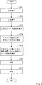
- FIG. It is a flowchart which shows an example of the resin molding method which concerns on Embodiment 1.
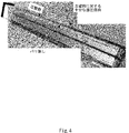
- FIG. It is a figure which shows the example of the molded product of the resin molded by the resin molding die which concerns on Embodiment 1.
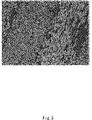
- FIG. It is a figure which shows the cross section of the molded article of the resin molded by the resin molding die which concerns on Embodiment 1.
- FIG. 1 shows the state of the resin molding die before pressing
- FIG. 2 shows the state of the resin molding die at the time of pressing.
- the resin molding mold 100 includes an upper mold (first mold) 101, a lower mold (second mold) 102, a slide mechanism 103, and a rubber member 104. Be prepared.
- the resin molding die 100 is used for molding a CFRP material (hereinafter, simply referred to as a resin) such as a prepreg.
- the upper mold 101 and the lower mold 102 are molds corresponding to the shape of the resin 200 to be molded. By opening and closing the upper mold 101 and the lower mold 102, the resin 200 is molded and the cured resin 200 is taken out.
- the lower mold 102 is located on the lower side (y-axis minus direction side) than the upper mold 101 in the vertical direction (y-axis direction), and receives the resin 200 to be molded.
- the upper die 101 moves downward in the vertical direction (minus direction on the y-axis) to press the resin 200 charged between the upper die 101 and the lower die 102.
- the slide mechanism 103 is configured to be slidable along the surface of the lower mold 102.
- the slide mechanism 103 is configured to be slidable in a direction perpendicular to the pressing direction of the resin 200 by the upper die 101 and the lower die 102, that is, in the horizontal direction (x-axis direction).
- the slide mechanism 103 is configured to be able to press the resin 200 in a direction different from the pressing direction of the resin 200 by the upper die 101 and the lower die 102 by sliding along the surface of the lower die 102.
- the slide mechanism 103 slides along the surface of the lower mold 102 so that the resin is in a direction perpendicular to the pressing direction of the resin 200 by the upper mold 101 and the lower mold 102, that is, in the horizontal direction.
- the 200 is configured to be pressable.
- the slide mechanism 103 can press the vertical wall portion (side surface portion of the resin 200) of the resin 200 with sufficient pressure.
- the slide mechanism 103 includes a pedestal 1031 and a pressing portion 1032.
- the pedestal 1031 is a plate-shaped metal member slidably installed along the surface of the lower mold 102.
- the pressing portion 1032 is a metal member having a surface 103a facing the slide direction (x-axis plus direction) of the slide mechanism 103, and is fixed on the pedestal 1031.
- the pedestal 1031 and the pressing portion 1032 may be integrally formed.
- the slide mechanism 103 slides along the surface of the lower mold 102 to press the vertical wall portion of the resin 200 using the pressing surface including the surface 103a.
- the case where the surface 103a faces the slide direction (x-axis plus direction) of the slide mechanism 103 is described as an example, but the present invention is not limited to this.
- the surface 103a may be oriented in any direction according to the shape of the molded product as long as the standing wall portion of the resin 200 can be pressed. However, the closer the direction of the surface 103a is to the slide direction of the slide mechanism 103, the more efficiently the pressure can be applied to the vertical wall portion of the resin 200.
- the surface 103a of the pressing portion 1032 is used as the pressing surface for pressing the resin 200.
- the surface of the pedestal 1031 does not have to be exposed on the cavity space 105 side, which will be described later.
- the slide mechanism 103 only the surface 103a of the pressing portion 1032 is used as the pressing surface for pressing the resin 200.
- the rubber member 104 is also called an elastomer and is made of, for example, a silicone material.
- the rubber member 104 is not limited to the case where a silicone material is used, and a polymer material having an elastic force may be used.
- a case where the rubber member 104 is made of a silicone material will be described as an example.
- the silicone material has a heat resistance of 200 degrees or higher and a shore A hardness of 30 to 90.
- the rubber member 104 is formed so as to at least cover the pressing surface (surfaces 103a, 103b) of the slide mechanism 103, the pressing surface of the slide mechanism 103, and the gap between the lower mold 102.
- the cavity space 105 that defines the shape of the resin 200 is the rubber member 104 that covers the surface (tool surface) of the upper die 101, the pressing surface (surfaces 103a, 103b) of the slide mechanism 103, and the like. Will be surrounded by.
- the resin 200 is charged into the cavity space 105 and held in pressure to be formed into a predetermined shape.
- the slide mechanism 103 By sliding along the surface of the lower mold 102, the slide mechanism 103 can press the standing wall portion of the resin 200 with sufficient pressure via the rubber member 104. As a result, it is possible to prevent resin withering, voids, and the like from occurring on the standing wall portion of the resin 200. Further, by covering the gap between the pressing surface of the slide mechanism 103 and the lower mold 102 with the rubber member 104, it is possible to prevent the resin from leaking into the gap. As a result, it is possible to prevent burrs and the like from being generated in the molded product.
- the slide mechanism 103 and the rubber member 104 have a fitting shape that fits each other.
- a convex fitting portion 103c is provided on the surface of the pedestal 1031 of the slide mechanism 103, and the rubber member 104 has a concave shape so as to face the convex fitting portion 103c.
- a fitting portion 104a is provided.
- the upper die 101 and the slide mechanism 103 have an inclined surface having a predetermined angle with respect to the pressing direction of the resin 200 by the upper die 101 and the lower die 102, respectively.
- the upper die 101 is provided with an inclined surface 101a
- the pressing portion 1032 of the slide mechanism 103 is provided with an inclined surface 103d.
- the inclined surface 101a and the inclined surface 103d come into contact with each other and slide when the upper die 101 moves in the pressing direction (y-axis minus direction).
- the vertically downward force of the upper die 101 becomes a horizontal (z-axis plus direction) force for pressing the vertical wall portion (side surface portion of the resin 200) of the resin 200 by the pressing surface 103a of the slide mechanism 103.
- a power source such as hydraulic pressure for sliding the slide mechanism 103 becomes unnecessary, so that the cost can be reduced.
- plates 111 and 112 having a low surface friction coefficient may be attached to the inclined surface 101a and the inclined surface 103d, respectively, as shown in FIGS. 1 and 2.
- Lubricating oil or the like may be applied.
- a power unit for sliding the slide mechanism 103 may be provided.
- the power unit any servomotor, actuator, or the like that can slide the slide mechanism 103 by power can be applied.
- the resin molding die 100 is provided with a return mechanism that returns the slide mechanism 103 after the slide to the position of the slide mechanism 103 before the slide (that is, before the press).
- the return mechanism may be, for example, a spring or the like, or may be the power unit described above. The provision of the return mechanism facilitates the removal of the resin 200 at the time of demolding.
- the lower mold 102 and the slide mechanism 103 have a guide structure that defines the slide direction of the slide mechanism 103.
- a groove is formed on the surface of the lower mold 102 along the x-axis direction, and a groove is formed on the bottom surface of the pedestal 1031 of the slide mechanism 103 so as to fit into the groove formed on the surface of the lower mold 102. Grooves are formed along the direction. As a result, it is possible to prevent carrying during sliding.
- FIG. 3 is a flowchart showing an example of a resin molding method using the resin molding die 100.
- the resin 200 is charged into the resin molding die 100 with the upper die 101, the lower die 102, and the slide mechanism 103 open (step S301).
- the inclined surface 101a (more specifically, the plate 111) of the upper die 101 and the inclined surface 103d (more specifically, the plate 112) of the slide mechanism 103 come into contact with each other (step S303).
- step S304 the vertically downward force of the upper die 101 is converted into a horizontal force for pressing the vertical wall portion of the resin 200 by the pressing surface 103a of the slide mechanism 103.
- the resin 200 is held by the surface (tool surface) of the upper mold 101 and the rubber member 104 that covers the pressing surface of the slide mechanism 103 (step S305). As a result, the resin 200 is formed into a predetermined shape defined by the cavity space 105 composed of the upper mold 101 and the rubber member 104.
- the resin 200 molded into a predetermined shape is cooled (step S306).
- the resin 200 formed into a predetermined shape is cured while maintaining the shape defined by the cavity space 105.
- step S307 the molded resin 200 is demolded into a molded product.
- the resin molding die 100 according to the present embodiment by using the rubber member and the slide mechanism, the standing wall portion of the resin can be pressed with a sufficiently large pressure, so that resin withering, voids and the like can be prevented. It can be prevented from occurring. Further, the resin molding die 100 according to the present embodiment can prevent burrs and the like from being generated by covering the gap between the pressing surface of the slide mechanism and the lower die with a rubber member. That is, the resin molding die 100 according to the present embodiment can perform high quality resin molding.
- FIG. 4 is a diagram showing an example of a molded product of the resin 200 actually molded by the resin molding die 100.
- FIG. 5 is a diagram showing a cross section of a molded product of the resin 200 actually molded by the resin molding die 100.
- the slide mechanism 103 is configured to be slidable along the surface of the lower mold 102
- the slide mechanism 103 may be configured to be slidable on the surface of a member fixed to the surface of the lower mold 102.
- the surface of the member fixed to the surface of the lower mold 102 can be said to be a part of the surface of the lower mold 102.
- the slide mechanism 103 is configured to be slidable along the surface of the lower mold 102
- the slide mechanism 103 may be configured to be slidable on the surface of the upper die 101 or the surface of a member fixed to the surface of the upper die 101.
- the surface of the member fixed to the surface of the upper mold 101 can be said to be a part of the surface of the upper mold 101.
- the case where the lower mold 102 is a fixed mold (fixed mold) and the upper mold 101 is a mold (moving mold) configured to be movable will be described as an example.
- the upper mold 101 may be a fixed mold and the lower mold 102 may be a moving mold.
- the cavity space 105 is surrounded by the surface of the upper die 101 and the rubber member 104 covering the pressing surfaces (surfaces 103a, 103b) of the slide mechanism 103 and the like will be described as an example.
- the cavity space 105 may be formed by a part of the surface of the lower mold 102 in addition to the rubber member 104 that covers the surface of the upper mold 101 and the pressing surface of the slide mechanism 103.
- a second rubber member may be further provided on the surface of the upper die 101 so as to be connected to the rubber member 104 which is the first rubber member, or separately from the rubber member 104. That is, the entire surface of the cavity space 105 may be covered with a rubber member.
- the cost can be reduced by using the rubber member not on the entire surface of the cavity space 105 but only on a part (for example, the pressing surface of the slide mechanism 103 and the gap between the pressing surface and the lower mold 102). ..
- the present invention is not limited to the above embodiment, and can be appropriately modified without departing from the spirit.
- a further divided mold may be provided.
- it may be provided with a mold divided for the side surface.
- the upper mold and the lower mold may be divided into a plurality of parts.
Landscapes
- Engineering & Computer Science (AREA)
- Mechanical Engineering (AREA)
- Manufacturing & Machinery (AREA)
- Moulds For Moulding Plastics Or The Like (AREA)
- Casting Or Compression Moulding Of Plastics Or The Like (AREA)
Abstract
Description
図1及び図2は、実施の形態1にかかる樹脂成形金型の一例を示す概略断面図である。なお、図1には樹脂成形金型のプレス前の状態が示されており、図2には樹脂成形金型のプレス時の状態が示されている。
続いて、図1及び図2に加えて、図3を用いて、樹脂成形金型100を用いた樹脂成形方法を説明する。図3は、樹脂成形金型100を用いた樹脂成形方法の一例を示すフローチャートである。
101 上型
101a 傾斜面
102 下型
103 スライド機構
103a 面
103b 面
103c 嵌合部
103d 傾斜面
104 ラバー部材
104a 嵌合部
105 キャビティ空間
111 プレート
112 プレート
200 樹脂
1031 台座
1032 押圧部
Claims (11)
- 第1金型と、
前記第1金型に対向配置された第2金型と、
前記第2金型の表面をスライド可能に構成され、且つ、前記第1金型及び前記第2金型による樹脂のプレス方向とは異なる方向を向いた面を含む押圧面を有する、スライド機構と、
前記スライド機構の押圧面と、前記押圧面及び前記第2金型の隙間と、を少なくとも覆うように形成された第1ラバー部材と、
を備えた、樹脂成形金型。 - 前記樹脂の形状を規定するキャビティ空間は、前記第1金型と、前記第1ラバー部材と、によって囲まれている、
請求項1に記載の樹脂成形金型。 - 前記樹脂の形状を規定するキャビティ空間は、前記第1金型、前記第2金型、及び、前記第1ラバー部材によって囲まれている、
請求項1に記載の樹脂成形金型。 - 前記第1ラバー部材は、前記第2金型の表面の一部をさらに覆うように形成され、
前記樹脂の形状を規定するキャビティ空間は、前記第1金型と、前記第1ラバー部材と、によって囲まれている、
請求項1に記載の樹脂成形金型。 - 前記第1金型の表面を覆うように形成された第2ラバー部材をさらに備え、
前記樹脂の形状を規定するキャビティ空間は、前記第1ラバー部材と、前記第2ラバー部材と、によって囲まれている、
請求項1に記載の樹脂成形金型。 - 前記スライド機構及び前記第1ラバー部材は、互いに嵌合する嵌合形状を有する、
請求項1~5の何れか一項に記載の樹脂成形金型。 - 前記第1金型及び前記スライド機構は、それぞれ、前記第1金型及び前記第2金型による前記樹脂のプレス方向に対して所定の角度を有し、且つ、前記樹脂のプレス時に互いに摺動するように形成された、傾斜面を有する、
請求項1~6の何れか一項に記載の樹脂成形金型。 - 前記スライド機構をスライドさせる動力部をさらに備えた、
請求項1~7の何れか一項に記載の樹脂成形金型。 - 脱型時に前記スライド機構をプレス前の位置に戻す戻り機構を備えた、
請求項1~8の何れか一項に記載の樹脂成形金型。 - 前記第2金型及び前記スライド機構は、前記スライド機構のスライド方向を規定するガイド構造を有する、
請求項1~9の何れか一項に記載の樹脂成形金型。 - 第1金型と、前記第1金型に対向配置された第2金型と、前記第2金型の表面をスライド可能に構成され、且つ、前記第1金型及び前記第2金型による樹脂のプレス方向とは異なる方向を向いた面を含む押圧面を有する、スライド機構と、前記スライド機構の押圧面と、前記押圧面及び前記第2金型の隙間と、を少なくとも覆うように形成された第1ラバー部材と、を備えた、樹脂成形金型を用いた樹脂成形方法であって、
前記第1金型と前記第2金型が開いた状態で、樹脂を投入し、
前記第1金型を前記第2金型に向けてプレスし、
前記第1金型の面と前記第1ラバー部材の面とによって前記樹脂を保圧し、
前記樹脂を冷却することによって硬化させ、
脱型する、
樹脂成形方法。
Priority Applications (4)
| Application Number | Priority Date | Filing Date | Title |
|---|---|---|---|
| US18/259,610 US12479132B2 (en) | 2021-01-08 | 2021-01-08 | Resin shaping mold and resin shaping method |
| PCT/JP2021/000493 WO2022149263A1 (ja) | 2021-01-08 | 2021-01-08 | 樹脂成形金型及び樹脂成形方法 |
| CN202180089651.0A CN116783049A (zh) | 2021-01-08 | 2021-01-08 | 树脂成形模具及树脂成形方法 |
| JP2022573878A JP7400996B2 (ja) | 2021-01-08 | 2021-01-08 | 樹脂成形金型及び樹脂成形方法 |
Applications Claiming Priority (1)
| Application Number | Priority Date | Filing Date | Title |
|---|---|---|---|
| PCT/JP2021/000493 WO2022149263A1 (ja) | 2021-01-08 | 2021-01-08 | 樹脂成形金型及び樹脂成形方法 |
Publications (1)
| Publication Number | Publication Date |
|---|---|
| WO2022149263A1 true WO2022149263A1 (ja) | 2022-07-14 |
Family
ID=82357852
Family Applications (1)
| Application Number | Title | Priority Date | Filing Date |
|---|---|---|---|
| PCT/JP2021/000493 Ceased WO2022149263A1 (ja) | 2021-01-08 | 2021-01-08 | 樹脂成形金型及び樹脂成形方法 |
Country Status (4)
| Country | Link |
|---|---|
| US (1) | US12479132B2 (ja) |
| JP (1) | JP7400996B2 (ja) |
| CN (1) | CN116783049A (ja) |
| WO (1) | WO2022149263A1 (ja) |
Citations (3)
| Publication number | Priority date | Publication date | Assignee | Title |
|---|---|---|---|---|
| JP2015009539A (ja) * | 2013-07-02 | 2015-01-19 | トヨタ紡織株式会社 | 板状成形体の製造方法 |
| JP2016215498A (ja) * | 2015-05-20 | 2016-12-22 | シャープ株式会社 | 熱プレス成形品、熱プレス成形金型、及び熱プレス成形品の製造方法 |
| JP2019151030A (ja) * | 2018-03-05 | 2019-09-12 | 株式会社The MOT Company | 金属−繊維強化樹脂複合成型体の製造方法 |
Family Cites Families (8)
| Publication number | Priority date | Publication date | Assignee | Title |
|---|---|---|---|---|
| JPH0761658B2 (ja) * | 1987-08-18 | 1995-07-05 | 金井 宏之 | 繊維強化樹脂製ホイ−ルの製造装置および製造法 |
| JPH02127017A (ja) * | 1988-11-08 | 1990-05-15 | Honda Motor Co Ltd | 樹脂製物品の成形装置および方法 |
| PT2716428T (pt) * | 2011-06-01 | 2016-11-04 | Comercial De Utiles Y Moldes Sa | Corrediça deslizante compacta para moldes de injeção |
| CN104690869A (zh) * | 2013-12-10 | 2015-06-10 | 赫比(苏州)通讯科技有限公司 | 一种热成型产品表面成型工艺 |
| JP6418895B2 (ja) | 2014-10-23 | 2018-11-07 | 信越ポリマー株式会社 | インサート成形用金型およびその金型を用いたインサート成形方法 |
| US10717225B2 (en) * | 2017-09-07 | 2020-07-21 | The Boeing Company | Drape forming end effector |
| JP7213725B2 (ja) * | 2019-03-08 | 2023-01-27 | 東海興業株式会社 | 射出成形品成形用の金型装置、射出成形品の製造方法 |
| TWI701091B (zh) * | 2019-06-25 | 2020-08-11 | 國立高雄科技大學 | 具有聯動式側向輔助加壓的成形模具 |
-
2021
- 2021-01-08 WO PCT/JP2021/000493 patent/WO2022149263A1/ja not_active Ceased
- 2021-01-08 US US18/259,610 patent/US12479132B2/en active Active
- 2021-01-08 CN CN202180089651.0A patent/CN116783049A/zh active Pending
- 2021-01-08 JP JP2022573878A patent/JP7400996B2/ja active Active
Patent Citations (3)
| Publication number | Priority date | Publication date | Assignee | Title |
|---|---|---|---|---|
| JP2015009539A (ja) * | 2013-07-02 | 2015-01-19 | トヨタ紡織株式会社 | 板状成形体の製造方法 |
| JP2016215498A (ja) * | 2015-05-20 | 2016-12-22 | シャープ株式会社 | 熱プレス成形品、熱プレス成形金型、及び熱プレス成形品の製造方法 |
| JP2019151030A (ja) * | 2018-03-05 | 2019-09-12 | 株式会社The MOT Company | 金属−繊維強化樹脂複合成型体の製造方法 |
Also Published As
| Publication number | Publication date |
|---|---|
| US20240051189A1 (en) | 2024-02-15 |
| JP7400996B2 (ja) | 2023-12-19 |
| CN116783049A (zh) | 2023-09-19 |
| US12479132B2 (en) | 2025-11-25 |
| JPWO2022149263A1 (ja) | 2022-07-14 |
Similar Documents
| Publication | Publication Date | Title |
|---|---|---|
| WO2013031209A1 (en) | Foam-molding parts manufacturing method, foam-molding part, and foam-mold | |
| CN103213240B (zh) | 具有模具安装位置调整机构的注塑成型机 | |
| CN105269718A (zh) | 制造汽车树脂部的方法以及汽车树脂部的制造装置 | |
| KR101144120B1 (ko) | 캐비티를 형성하는 무빙 코어를 갖는 사출압축성형용 금형 | |
| JP7400996B2 (ja) | 樹脂成形金型及び樹脂成形方法 | |
| CN100413670C (zh) | 模塑方法 | |
| JP4380629B2 (ja) | 成形品の金型 | |
| JP4139351B2 (ja) | 射出成形金型装置および射出成形方法 | |
| KR101841546B1 (ko) | 자동차용 성형 사출성형장치 | |
| US20180272575A1 (en) | Mold for producing a part made from plastic materials, comprising an optimized sealing system | |
| JP6195071B2 (ja) | 表皮一体樹脂成形装置 | |
| JP2018034390A (ja) | 射出圧縮成形金型および射出圧縮成形方法 | |
| US20210268702A1 (en) | Injection molding die, and method of manufacturing molded product | |
| JP4939949B2 (ja) | 射出成形金型 | |
| TWI629163B (zh) | 沖壓機構、沖壓方法、壓縮成形裝置以及壓縮成形方法 | |
| CN109501073B (zh) | 一种前模弹滑脱模装置 | |
| JP4136782B2 (ja) | 金型 | |
| CN222403396U (zh) | 一种金属注塑及压铸一体成型装置 | |
| CN222554073U (zh) | 压力注塑成型模具 | |
| CN116194270B (zh) | 用于注射模制的模制工具 | |
| JP6557545B2 (ja) | プレス成形装置及びプレス成形方法 | |
| CN218798994U (zh) | 一种压铸模具定模结构 | |
| CN115042384B (zh) | 用于加工杆端注塑轴承并具有浮动封胶面的模具结构 | |
| JP7522134B2 (ja) | ホットプレス成型装置およびブランクのホットプレス成型方法 | |
| JP2004306527A (ja) | 射出成形金型 |
Legal Events
| Date | Code | Title | Description |
|---|---|---|---|
| 121 | Ep: the epo has been informed by wipo that ep was designated in this application |
Ref document number: 21917489 Country of ref document: EP Kind code of ref document: A1 |
|
| ENP | Entry into the national phase |
Ref document number: 2022573878 Country of ref document: JP Kind code of ref document: A |
|
| WWE | Wipo information: entry into national phase |
Ref document number: 18259610 Country of ref document: US |
|
| WWE | Wipo information: entry into national phase |
Ref document number: 202180089651.0 Country of ref document: CN |
|
| NENP | Non-entry into the national phase |
Ref country code: DE |
|
| 122 | Ep: pct application non-entry in european phase |
Ref document number: 21917489 Country of ref document: EP Kind code of ref document: A1 |
|
| WWG | Wipo information: grant in national office |
Ref document number: 18259610 Country of ref document: US |