WO2022118707A1 - カム曲線生成装置、カム曲線生成方法、および、プログラム - Google Patents
カム曲線生成装置、カム曲線生成方法、および、プログラム Download PDFInfo
- Publication number
- WO2022118707A1 WO2022118707A1 PCT/JP2021/042976 JP2021042976W WO2022118707A1 WO 2022118707 A1 WO2022118707 A1 WO 2022118707A1 JP 2021042976 W JP2021042976 W JP 2021042976W WO 2022118707 A1 WO2022118707 A1 WO 2022118707A1
- Authority
- WO
- WIPO (PCT)
- Prior art keywords
- section
- sub
- cam curve
- slave axis
- acceleration
- Prior art date
- Legal status (The legal status is an assumption and is not a legal conclusion. Google has not performed a legal analysis and makes no representation as to the accuracy of the status listed.)
- Ceased
Links
Images




Classifications
-
- G—PHYSICS
- G05—CONTROLLING; REGULATING
- G05B—CONTROL OR REGULATING SYSTEMS IN GENERAL; FUNCTIONAL ELEMENTS OF SUCH SYSTEMS; MONITORING OR TESTING ARRANGEMENTS FOR SUCH SYSTEMS OR ELEMENTS
- G05B19/00—Program-control systems
- G05B19/02—Program-control systems electric
- G05B19/18—Numerical control [NC], i.e. automatically operating machines, in particular machine tools, e.g. in a manufacturing environment, so as to execute positioning, movement or co-ordinated operations by means of program data in numerical form
- G05B19/19—Numerical control [NC], i.e. automatically operating machines, in particular machine tools, e.g. in a manufacturing environment, so as to execute positioning, movement or co-ordinated operations by means of program data in numerical form characterised by positioning or contouring control systems, e.g. to control position from one programmed point to another or to control movement along a programmed continuous path
- G05B19/40—Open loop systems, e.g. using stepping motor
-
- G—PHYSICS
- G05—CONTROLLING; REGULATING
- G05B—CONTROL OR REGULATING SYSTEMS IN GENERAL; FUNCTIONAL ELEMENTS OF SUCH SYSTEMS; MONITORING OR TESTING ARRANGEMENTS FOR SUCH SYSTEMS OR ELEMENTS
- G05B19/00—Program-control systems
- G05B19/02—Program-control systems electric
- G05B19/18—Numerical control [NC], i.e. automatically operating machines, in particular machine tools, e.g. in a manufacturing environment, so as to execute positioning, movement or co-ordinated operations by means of program data in numerical form
- G05B19/416—Numerical control [NC], i.e. automatically operating machines, in particular machine tools, e.g. in a manufacturing environment, so as to execute positioning, movement or co-ordinated operations by means of program data in numerical form characterised by control of velocity, acceleration or deceleration
-
- G—PHYSICS
- G05—CONTROLLING; REGULATING
- G05B—CONTROL OR REGULATING SYSTEMS IN GENERAL; FUNCTIONAL ELEMENTS OF SUCH SYSTEMS; MONITORING OR TESTING ARRANGEMENTS FOR SUCH SYSTEMS OR ELEMENTS
- G05B2219/00—Program-control systems
- G05B2219/30—Nc systems
- G05B2219/34—Director, elements to supervisory
- G05B2219/34343—Generation of electronic cam data from nc program
-
- G—PHYSICS
- G05—CONTROLLING; REGULATING
- G05B—CONTROL OR REGULATING SYSTEMS IN GENERAL; FUNCTIONAL ELEMENTS OF SUCH SYSTEMS; MONITORING OR TESTING ARRANGEMENTS FOR SUCH SYSTEMS OR ELEMENTS
- G05B2219/00—Program-control systems
- G05B2219/30—Nc systems
- G05B2219/35—Nc in input of data, input till input file format
- G05B2219/35108—Generate offset tool moving path in restrained curved plane
Definitions
- the present disclosure relates to a cam curve generator that generates a cam curve for realizing electronic cam control that controls the position of the slave axis in synchronization with the position of the main axis.
- the smooth connection between the out-of-section cam curve and the generated cam curve means that the position of the slave axis, the velocity of the slave axis, and the acceleration of the slave axis at the connection point between the out-of-section cam curve and the generated cam curve are smoothly connected.
- the fact that a certain physical quantity in the out-of-interval cam curve and the generated cam curve is continuous at the connection point means that the physical quantities match at the connection point.
- the cam curve corresponding to the boundary condition between the section start end and the section end is uniquely determined. Therefore, depending on the boundary conditions between the beginning of the section and the end of the section, a cam curve in which the velocity of the slave axis or the acceleration of the slave axis fluctuates relatively greatly may be generated in the application section.
- the present disclosure can generate a cam curve that suppresses fluctuations in the velocity of the slave axis and the acceleration of the slave axis within the applicable section while smoothly connecting to the cam curve outside the section. It is an object of the present invention to provide an apparatus, a cam curve generation method, and a program for causing a cam curve generation apparatus to execute a cam curve generation process.
- the cam curve generator is an electronic cam-controlled cam curve generator that controls the position of the slave axis.
- the cam curve generation device includes a boundary condition acquisition unit, a division condition acquisition unit, an interval division unit, and a cam curve generation unit.
- the boundary condition acquisition unit acquires the boundary condition of the application section for which the cam curve is generated within the range in which the position of the main axis changes.
- the division condition acquisition unit acquires a division condition for dividing the applicable section into a plurality of sub-sections.
- the section division section divides the applicable section into the plurality of sub-sections so as to satisfy the division condition.
- the cam curve generation unit generates a cam curve in the application section so as to satisfy the boundary condition.
- Each of the plurality of sub-sections is either a sub-section in which the acceleration of the slave axis increases monotonically, a sub-section in which the acceleration of the slave axis monotonically decreases, or a sub-section in which the acceleration of the slave axis does not change.
- the division condition includes the length and type of the plurality of sub-sections.
- the boundary condition includes the position of the slave axis at the start and end of the application section, the velocity of the slave axis, and the acceleration of the slave axis.
- the cam curve generation unit further produces the cam curve so that the position of the slave axis, the velocity of the slave axis, and the acceleration of the slave axis are continuous at each of the boundaries of the plurality of sub-sections. Generate.
- the cam curve generation method is a method of generating a cam curve for realizing electronic cam control for controlling the position of the slave axis.
- the cam curve generation method includes a first step, a second step, a third step, and a fourth step.
- the boundary condition of the application section for which the cam curve is generated is acquired in the range where the position of the main axis changes.
- the second step acquires a division condition for dividing the application section into a plurality of sub-sections.
- the third step divides the application section into the plurality of sub-sections so as to satisfy the division condition.
- the fourth step generates the cam curve in the application section so as to satisfy the boundary condition.
- Each of the plurality of sub-sections is either a sub-section in which the acceleration of the slave axis increases monotonically, a sub-section in which the acceleration of the slave axis monotonically decreases, or a sub-section in which the acceleration of the slave axis does not change.
- the division condition includes the length and type of the plurality of sub-sections. Boundary conditions include the position of the slave axis at the beginning and end of the application section, the velocity of the slave axis, and the acceleration of the slave axis.
- a cam curve is further generated so that the position of the slave axis, the velocity of the slave axis, and the acceleration of the slave axis are continuous at each of the boundaries of the plurality of sub-sections.
- the program according to another aspect of the present disclosure is a program for causing a cam curve generator to execute a cam curve generation process for generating a cam curve for realizing electronic cam control for controlling the position of a slave axis. ..
- the program comprises a first step, a second step, a third step and a fourth step.
- the cam curve generation process acquires the boundary condition of the application section for which the cam curve is generated within the range in which the position of the main axis changes.
- the division condition for dividing the application section into a plurality of sub-sections is acquired.
- the application section is divided into the plurality of sub-sections so as to satisfy the division condition.
- the fourth step generates the cam curve in the application section so as to satisfy the boundary condition.
- Each of the plurality of sub-sections is either a sub-section in which the acceleration of the slave axis increases monotonically, a sub-section in which the acceleration of the slave axis monotonically decreases, or a sub-section in which the acceleration of the slave axis does not change. be.
- the division condition includes the length and type of the plurality of sub-sections.
- the boundary condition includes the position of the slave axis at the start and end of the application section, the velocity of the slave axis, and the acceleration of the slave axis.
- the cam curve is generated so that the position of the slave axis, the velocity of the slave axis, and the acceleration of the slave axis are continuous at each of the boundaries of the plurality of subsections. ..
- cam curve generator According to the cam curve generator, cam curve generator and program according to the present disclosure, fluctuations in the velocity of the slave axis and the acceleration of the slave axis within the applicable section are suppressed while smoothly connecting to the cam curve outside the section. A cam curve can be generated.
- FIG. 1 is a block diagram showing an example of the configuration of the cam curve generation system according to the first embodiment.
- FIG. 2 is a flowchart of the first cam curve generation process according to the first embodiment.
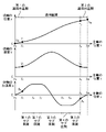
- FIG. 3 is a waveform diagram showing an example of a cam curve according to the first embodiment.
- FIG. 4 is a waveform diagram showing another example of the cam curve according to the first embodiment.
- FIG. 5 is a block diagram showing an example of the configuration of the cam curve generation system according to the second embodiment.
- FIG. 6 is a flowchart of the second cam curve generation process according to the second embodiment.
- the slave axis control method by electronic cam control is a control method that outputs the slave axis position command to the servomotor based on the cam curve that defines the relationship between the position of the main axis and the position of the slave axis.
- the control method of the slave axis by the electronic cam control has advantages such that the operation pattern can be easily changed and the mechanism can be simplified as compared with the control method of the slave axis using the mechanical cam mechanism.
- the cam curve is generated according to the operation pattern required for industrial equipment.
- a method of generating a cam curve there is known a method of dividing an operation pattern into a plurality of sections, generating a cam curve for each section, and connecting the cam curves of the plurality of sections to generate one cam curve.
- the slave shaft is the end sealer shaft of the pillow packaging machine
- the section from the start position to the end position of one seal hereinafter, also referred to as “seal section” and the next time from the end position of one seal.
- delay section a method of generating a cam curve by dividing the period up to the start position of the seal
- the sealing surface of the end sealer needs to be in contact with the predetermined sealing portion of the film, so the moving speed of the end sealer is uniquely determined with respect to the transport speed of the film. Therefore, the cam curve of the end sealer axis in the seal section is uniquely determined.
- the sealing surface of the end sealer operates away from the film, so that the moving speed of the end sealer can be ambiguously determined with respect to the transport speed of the film. Therefore, the cam curve of the end sealer axis in the relay section is ambiguously determined.
- the speed of the slave axis obtained by first-order differentiating the cam curve at the position of the main axis is obtained by second-order differentiation.
- the acceleration of the slave axis may be discontinuous at the boundary between two adjacent sections.
- the cam is defined by a fifth-order function for the position of the slave axis with respect to the position of the spindle, a quaternary function for the velocity of the slave axis with respect to the position of the spindle, and a cubic function for the acceleration of the slave axis with respect to the position of the spindle.
- the inventors can generate a cam curve that suppresses fluctuations in the velocity of the slave axis and the acceleration of the slave axis within the applicable section while smoothly connecting to the cam curve outside the section.
- the cam curve generator generates an electronic cam-controlled cam curve that controls the position of the slave axis.
- the cam curve generation device includes a boundary condition acquisition unit, a division condition acquisition unit, an interval division unit, and a cam curve generation unit.
- the boundary condition acquisition unit acquires the boundary condition of the application section for which the cam curve is generated within the range in which the position of the main axis changes.
- the division condition acquisition unit divides the applicable section into a plurality of sub-sections.
- the section division section divides the applicable section into the plurality of sub-sections so as to satisfy the division condition.
- the cam curve generation unit generates the cam curve in the application section so as to satisfy the boundary condition.
- Each of the plurality of sub-sections is either a sub-section in which the acceleration of the slave axis increases monotonically, a sub-section in which the acceleration of the slave axis monotonically decreases, or a sub-section in which the acceleration of the slave axis does not change.
- the division condition includes the length of the plurality of sub-sections and the type.
- the boundary condition includes the position of the slave axis at the start and end of the application section, the velocity of the slave axis, and the acceleration of the slave axis.
- the cam curve generation unit generates the cam curve so that the position of the slave axis, the velocity of the slave axis, and the acceleration of the slave axis are continuous at each of the boundaries of the plurality of sub-sections. ..
- the position of the slave axis, the velocity of the slave axis, and the acceleration of the slave axis at the start and end of the application section are determined by the boundary conditions to be acquired. Therefore, according to the cam curve generator having the above configuration, it is possible to generate a cam curve that smoothly connects to the out-of-section cam curve outside the applicable section by setting the acquired boundary conditions to be appropriate.
- the velocity of the slave axis in the applicable section and the acceleration of the slave axis are determined by the division conditions to be acquired. Therefore, according to the cam curve generator having the above configuration, a cam curve that suppresses fluctuations in the velocity of the slave axis and the acceleration of the slave axis within the applicable section can be obtained by setting the division conditions to be acquired appropriately. Can be generated.
- the cam curve generator having the above configuration, it is possible to generate a cam curve that suppresses fluctuations in the velocity of the slave axis and the acceleration of the slave axis within the applicable section while smoothly connecting to the cam curve outside the section. Can be done.
- the acceleration of the slave axis extends from the start end to the end of the sub-section.
- the cam curve may be generated so that the waveform of the above is in the shape of a quarter period portion up to the apex of the sine wave.
- the acceleration of the slave axis extends from the start end to the end of the sub-section.
- the cam curve may be generated so that the waveform of the above is in the shape of a half-period portion from the apex of the sine wave.
- the acceleration of the slave axis extends from the start end to the end of the sub-section.
- the cam curve may be generated so that the waveform of the above is in the shape of a quarter period portion from the apex of the sine wave.
- the acceleration of the slave axis extends from the start end to the end of the sub-section.
- the cam curve may be generated so that the waveform of is a waveform defined by the linear polynomial of the position of the main axis.
- the plurality of sub-sections are five sub-sections of a first sub-section, a second sub-section, a third sub-section, a fourth sub-section, and a fifth sub-section, which are continuous in order. May be.
- the first sub-section, the third sub-section, and the fifth sub-section are sub-sections of the type in which the acceleration of the slave axis monotonically increases or decreases, and the second sub-section and the first sub-section.
- the sub-section of 4 may be a sub-section of a type in which the acceleration of the slave axis does not change.
- the acceleration of the slave axis in the second sub-section and the fourth sub-section may be a value other than 0.
- the plurality of sub-sections are continuous in order, the first sub-section, the second sub-section, the third sub-section, the fourth sub-section, the fifth sub-section, the sixth sub-section, and the third sub-section. It may be 7 sub-sections with 7 sub-sections.
- the first sub-section, the third sub-section, the fifth sub-section, and the seventh sub-section may be a sub-section of the type in which the acceleration of the slave axis increases or decreases monotonically.
- the second sub-section, the fourth sub-section, and the sixth sub-section may be a sub-section of a type in which the acceleration of the slave axis does not change.
- the acceleration of the slave axis in the second sub-section and the sixth sub-section is a value other than 0, and the acceleration of the slave axis in the fourth sub-section is 0. good.
- a section setting unit may be provided which divides the range in which the position of the main axis transitions into the applicable section and the non-applicable section other than the applicable section.
- a ready-made cam curve storage unit and a boundary condition calculation unit may be provided.
- the prefabricated cam curve storage unit stores a prefabricated cam curve generated in advance.
- the boundary condition calculation unit calculates the following values. That is, from the prefabricated cam curve, the position of the first slave shaft of the slave shaft at the position of the first spindle, the velocity of the first slave shaft of the slave shaft at the position of the first spindle, and the said. The acceleration of the first slave axis of the slave axis at the position of the first spindle, the position of the second spindle at a time after the position of the first spindle, and the slave at the position of the second spindle.
- the velocity of the second slave shaft of the shaft and the acceleration of the second slave shaft of the slave shaft at the position of the second spindle are calculated. Further, in the range in which the position of the main axis transitions in the ready-made cam curve, the first section from the position of the first main axis to the position of the second main axis is defined as the applicable section, and the boundary conditions shown below are defined. Is calculated. That is, the position of the first slave axis, the velocity of the first slave axis, and the acceleration of the first slave axis are the position of the slave axis at the start end, the velocity of the slave axis at the start end, and the start end. It is a boundary condition to be the acceleration of the slave axis in.
- the position of the second slave shaft, the velocity of the second slave shaft, and the acceleration of the second slave shaft are the positions of the slave shaft at the end and the slave shaft at the end. It is a boundary condition which is the velocity and the acceleration of the slave axis at the end.
- the boundary condition acquisition unit acquires the boundary condition related to the start end and the boundary condition related to the start end calculated by the boundary condition calculation unit.
- the division condition acquisition unit acquires the division condition with the first section as the application section.
- the section division section divides the applicable section into the plurality of sub-sections with the first section as the applicable section.
- the cam curve generation unit may generate the cam curve with the first section as the application section.
- the cam curve generation method generates a cam curve for realizing electronic cam control for controlling the position of the slave axis.
- the cam curve generation method includes a first step, a second step, a third step, and a fourth step.
- the boundary condition of the application section to be generated of the cam curve is acquired in the range where the position of the main axis changes.
- the division condition for dividing the application section into a plurality of sub-sections is acquired.
- the third step divides the application section into the plurality of sub-sections so as to satisfy the division condition.
- the fourth step generates the cam curve in the application section so as to satisfy the boundary condition.
- Each of the plurality of sub-sections is either a sub-section in which the acceleration of the slave axis increases monotonically, a sub-section in which the acceleration of the slave axis monotonically decreases, or a sub-section in which the acceleration of the slave axis does not change.
- the division condition includes the length of the plurality of sub-sections and the type. Boundary conditions include the position of the slave axis at the beginning and end of the application section, the velocity of the slave axis, and the acceleration of the slave axis.
- the cam curve is further formed so that the position of the slave axis, the velocity of the slave axis, and the acceleration of the slave axis are continuous at each of the boundaries of the plurality of subsections. Generate.
- the position of the slave axis, the velocity of the slave axis, and the acceleration of the slave axis at the start and end of the application section are determined by the boundary conditions to be acquired. Therefore, according to the above-mentioned cam curve generation method, it is possible to generate a cam curve that smoothly connects to the out-of-section cam curve outside the applicable section by setting the boundary conditions to be acquired appropriately.
- the velocity of the slave axis and the acceleration of the slave axis in the applicable section are determined by the division conditions to be acquired. Therefore, according to the above-mentioned cam curve generation method, a cam curve that suppresses fluctuations in the velocity of the slave axis and the acceleration of the slave axis within the applicable section is generated by making the acquisition division conditions appropriate. be able to.
- cam curve generation method it is possible to generate a cam curve that suppresses fluctuations in the velocity of the slave axis and the acceleration of the slave axis within the applicable section while smoothly connecting to the cam curve outside the section. ..
- the program according to another aspect of the present disclosure is a program for causing a cam curve generator to execute a cam curve generation process for generating a cam curve for realizing electronic cam control for controlling the position of a slave axis. ..
- the program comprises a first step, a second step, a third step, and a fourth step.
- the cam curve generation process acquires the boundary condition of the application section for which the cam curve is generated in the range where the position of the main axis changes.
- the division condition for dividing the applicable section into a plurality of sub-sections is acquired.
- the applicable section is divided into a plurality of sub-sections so as to satisfy the division condition.
- a cam curve in the application section is generated so as to satisfy the boundary condition.
- Each of the plurality of sub-sections is either a sub-section in which the acceleration of the slave axis increases or decreases monotonically, or a sub-section in which the acceleration of the slave axis does not change.
- the division condition includes the length and the type for each of the plurality of sub-sections.
- Boundary conditions include the position of the slave axis at the beginning and end of the applicable section, the velocity of the slave axis, and the acceleration of the slave axis.
- a cam curve is further generated so that the position of the slave axis, the velocity of the slave axis, and the acceleration of the slave axis are continuous at each of the boundaries of the plurality of sub-sections.
- the position of the slave axis, the velocity of the slave axis, and the acceleration of the slave axis at the start and end of the applicable section are determined by the boundary conditions to be acquired. Therefore, according to the above program, by setting the boundary conditions to be acquired appropriately, it is possible to generate a cam curve that smoothly connects to the cam curve outside the applicable section.
- the velocity of the slave axis and the acceleration of the slave axis in the applicable section are determined by the division conditions to be acquired. Therefore, according to the above program, it is possible to generate a cam curve that suppresses fluctuations in the velocity of the slave axis and the acceleration of the slave axis within the applicable section by setting the division conditions to be acquired appropriately. ..
- the comprehensive or specific embodiment of the present disclosure may be realized by a recording medium such as a system, a method, an integrated circuit, a computer program or a computer-readable CD-ROM, and the system, the method, the integrated circuit, the computer. It may be realized by any combination of a program and a recording medium.
- FIG. 1 is a block diagram showing an example of the configuration of the cam curve generation system 1 according to the first embodiment.
- the cam curve generation system 1 includes a cam curve generation device 100, a servo control device 200, and a motor 300.
- the cam curve generator 100 is a cam curve for realizing electronic cam control that controls the position of the slave axis in synchronization with the position of the main axis, and is a cam that defines the relationship between the position of the main axis and the position of the slave axis. Generate a curve.
- the cam curve may be, for example, a function that defines the relationship between the position of the main axis and the position of the slave axis, or may be a data table.
- the cam curve may further define, for example, the relationship between the position of the spindle and the velocity of the slave axis, the relationship between the position of the spindle and the acceleration of the slave axis, or the relationship between the position of the spindle and the jerk of the slave axis. good. That is, the cam curve further defines a function that defines the relationship between the position of the main axis and the velocity of the slave axis, the relationship between the position of the main axis and the acceleration of the slave axis, or the relationship between the position of the main axis and the jerk of the slave axis. It may be included or it may include a data table.
- the cam curve generator 100 generates and outputs a command to the slave axis based on the generated cam curve and the spindle position indicating the position of the spindle.
- the command may be, for example, a position command, a speed command, or a torque command.
- the spindle position is a position signal that serves as a reference for synchronization of the cam curve generation system 1.
- the spindle position may be, for example, a position command to the spindle, a signal indicating the position of the spindle acquired by an external device such as a pulser or an encoder, or synchronized with the spindle. It may be a signal indicating the position of a shaft other than the main shaft or the position of a movable part of an industrial device such as a belt conveyor.
- the cam curve generator 100 may generate this position command.
- the main axis is not necessarily a real axis, but may be a virtual axis.
- the motor 300 drives the slave shaft.
- the servo control device 200 controls the motor 300 based on the command to the slave shaft output from the cam curve generation device 100.
- the cam curve generation device 100 includes an input reception unit 10, an interval information acquisition unit 20, a division condition acquisition unit 30, a boundary condition acquisition unit 40, a section setting unit 50, and an interval division unit. 60, a cam curve generation unit 70, a cam curve storage unit 80, and a slave axis command generation unit 90 are provided.
- the cam curve generator 100 may be realized by, for example, a computer including a processor and a memory.
- each of the components constituting the cam curve generator 100 may be realized, for example, by the processor executing a program stored in the memory.
- the input receiving unit 10 receives the input of the cam curve generation condition.
- the cam curve generation condition is the section information indicating the applicable section for which the cam curve is generated, the boundary condition of the applicable section, and the division that divides the applicable section into a plurality of sub-sections in the range in which the position of the main axis changes. Including conditions.
- the section information acquisition unit 20 acquires section information from the cam curve generation conditions accepted by the input reception unit 10.
- the section information will be described as being included in the cam curve generation condition, but the section information may be predetermined, for example.
- the section information acquisition unit 20 may store predetermined section information instead of acquiring the section information from the cam curve generation condition accepted by the input reception unit 10.
- the section information is shown as a coordinate value in an xy orthogonal coordinate system in which the position of the main axis is the x-axis (horizontal axis) and the position of the slave axis is the y-axis (vertical axis). Is done.
- the coordinate values may be, for example, only the position of the main axis, or may be the position of the main axis and the position of the slave axis.
- the coordinate values will be described as being the position of the main axis and the position of the slave axis.
- the section setting unit 50 divides the range in which the position of the main axis changes into an applicable section and a non-applicable section other than the applicable section based on the section information acquired by the section information acquisition unit 20. As a result, the section setting unit 50 sets the applicable section and the non-applicable section.
- the applicable section corresponds to a section in which the cam curve can be ambiguously determined, for example, a relay section in the case where the slave axis is the end sealer axis of the pillow packaging machine, and the non-applicable section is, for example, a slave section.
- a section in which the cam curve is uniquely determined is applicable, such as a seal section when the shaft is the end sealer shaft of the pillow packaging machine.
- the section setting unit 50 acquires or generates an out-of-section cam curve that defines the relationship between the position of the main axis and the position of the slave axis in the non-applicable section from the outside.
- the section setting unit 50 When the section setting unit 50 generates an out-of-section cam curve, for example, in addition to the coordinate values in the section information, the section setting unit 50 externally determines the dimensions of various parts in the industrial equipment, the operating conditions of the machining process performed by the industrial equipment, and the like. It may be acquired and an out-of-interval cam curve may be generated based on these coordinate values, dimensions, operating conditions, and the like.
- the out-of-section cam curve further includes, for example, the relationship between the position of the spindle and the velocity of the slave axis, the relationship between the position of the spindle and the acceleration of the slave axis, or the position of the spindle and the jerk of the slave axis in the non-applicable section.
- the relationship may be specified.
- the out-of-section cam curve acquired or generated by the section setting unit 50 is stored in the cam curve storage unit 80 described later.
- the division condition acquisition unit 30 acquires the division condition from the cam curve generation condition accepted by the input reception unit 10.
- the division condition will be described as being included in the cam curve generation condition, but the division condition may be predetermined, for example.
- the division condition acquisition unit 30 may store a predetermined division condition instead of acquiring the division condition from the cam curve generation condition accepted by the input reception unit 10.
- the division condition includes the number of divisions indicating the number of sub-sections to be divided, the length of each of the plurality of sub-sections, and the type of each of the plurality of sub-sections.
- the length of the sub section is information that can calculate the difference between the position of the main axis at the start end of the sub section and the position of the main axis at the end of the sub section.
- the length of the sub-section does not necessarily have to be limited, for example, the distance between the position of the main axis at the beginning of the sub-section and the position of the main axis at the end of the sub-section.
- the type is information indicating whether the sub-section in which the acceleration of the slave axis increases or decreases monotonically or the sub-section in which the acceleration of the slave axis does not change.
- the section division unit 60 divides the applicable section into a plurality of sub-sections so as to satisfy the division condition based on the division condition acquired by the division condition acquisition unit 30.
- the section division unit 60 divides the applicable section into a sub-section in which the acceleration of the slave axis increases or decreases monotonically, or a sub-section in which the acceleration of the slave axis does not change.
- the section division unit 60 When the application section is divided into a plurality of sub-sections, the section division unit 60 outputs information indicating each sub-section to the cam curve generation unit 70.
- the information indicating the sub-section may be, for example, the coordinate value of the position of the main axis at the boundary of the sub-section and the type of the sub-section.
- the boundary condition acquisition unit 40 acquires the boundary condition from the cam curve generation condition accepted by the input reception unit 10.
- Boundary conditions include the position of the slave axis at the beginning and end of the applicable section, the velocity of the slave axis, and the acceleration of the slave axis.
- the boundary condition is described as being included in the cam curve generation condition, but the boundary condition may be predetermined, for example.
- the boundary condition acquisition unit 40 may store a predetermined boundary condition instead of acquiring the boundary condition from the cam curve generation condition accepted by the input reception unit 10.
- the boundary condition acquisition unit 40 instead of acquiring the boundary condition from the cam curve generation condition accepted by the input reception unit 10, the boundary condition acquisition unit 40 generates the boundary condition from the out-of-section cam curve stored in the cam curve storage unit 80. May be good.
- the boundary condition acquisition unit 40 determines, for example, the position of the slave axis, the velocity of the slave axis, and the acceleration of the slave axis at the end of the non-applicable cam curve of the adjacent non-applicable section before the applicable section. They may be calculated as the position of the slave axis, the velocity of the slave axis, and the acceleration of the slave axis at the beginning of the application section, respectively.
- the position of the slave axis at the beginning of the non-applicable cam curve of the non-applicable section adjacent to the applicable section, the velocity of the slave axis, and the acceleration of the slave axis are the positions of the slave axis at the end of the applicable section, respectively.
- the speed of the slave axis and the acceleration of the slave axis may be calculated.
- the cam curve generation unit 70 generates a cam curve in the application section based on the boundary condition acquired by the boundary condition acquisition unit 40 so as to satisfy the boundary condition. At this time, the cam curve generation unit 70 determines the position of the slave axis, the speed of the slave axis, and the slave axis at each of the boundaries of the plurality of sub-sections based on the information indicating the sub-section output from the section division unit 60. Generate a cam curve so that the acceleration of the axis is continuous.
- cam curve generated by the cam curve generation unit 70 A specific example of the cam curve generated by the cam curve generation unit 70 will be described later.
- the cam curve storage unit 80 stores the cam curve generated by the cam curve generation unit 70. Further, as described above, the cam curve storage unit 80 stores the out-of-section cam curve acquired or generated by the section setting unit 50.
- the cam curve storage unit 80 may store the cam curve or the out-of-section cam curve itself, or the cam curve or the out-of-section cam curve defines the relationship between the position of the main axis and the position of the slave axis. If it is a function, the factor data of the function may be stored, or if the cam curve or the out-of-section cam curve is a data table that defines the relationship between the position of the main axis and the position of the slave axis. May store the numerical values of the data constituting the data table.
- the slave axis command generation unit 90 acquires the spindle position and generates a command to the slave axis based on the spindle position and the cam curve stored in the cam curve storage unit 80 or the out-of-section cam curve. Output.
- the cam curve generation device 100 having the above configuration performs a first cam curve generation process for generating a cam curve.
- FIG. 2 is a flowchart of the first cam curve generation process.
- the first cam curve generation process is started, for example, by performing an operation on the cam curve generation device 100 to start the first cam curve generation process.
- the section information acquisition unit 20 acquires section information (step S10). More specifically, the section information acquisition unit 20 acquires section information from the cam curve generation conditions accepted by the input reception unit 10. When the section information is acquired by the section information acquisition unit 20, the section setting unit 50 sets the applicable section and the non-applicable section based on the section information (step S20).
- the division condition acquisition unit 30 acquires the division condition (step S30). More specifically, the division condition acquisition unit 30 acquires the division condition from the cam curve generation condition accepted by the input reception unit 10.
- the section division unit 60 divides the applicable section into a plurality of sub-sections based on the division condition so as to satisfy the division condition (step S40). Then, the section division unit 60 outputs information indicating each sub-section to the cam curve generation unit 70.
- the boundary condition acquisition unit 40 acquires the boundary condition (step S50). More specifically, the boundary condition acquisition unit 40 acquires the boundary condition from the cam curve generation condition accepted by the input reception unit 10.
- the cam curve generation unit 70 calculates the cam curve in the application section so as to satisfy the boundary condition based on the boundary condition acquired by the boundary condition acquisition unit 40. Generate.
- the cam curve generation unit 70 determines the position of the slave axis, the speed of the slave axis, and the slave axis at each of the boundaries of the plurality of sub-sections based on the information indicating the sub-section output from the section division unit 60.
- a cam curve is generated so that the acceleration of the axis is continuous (step S60).
- step S60 the cam curve generation device 100 ends the first cam curve generation process.
- FIG. 3 is a waveform diagram showing an example of the cam curve generated by the cam curve generation unit 70 in the process of step S60.
- the upper waveform diagram in FIG. 3 shows a cam curve that defines the relationship between the position of the main axis and the position of the slave axis.
- the horizontal axis (x axis) indicates the position x of the main axis
- the vertical axis (y axis) indicates the position y of the slave axis.
- the waveform diagram in the middle of FIG. 3 shows a cam curve that defines the relationship between the position of the main axis and the speed of the slave axis.
- the horizontal axis (x axis) indicates the position x of the main axis
- the vertical axis (v axis) indicates the velocity v of the slave axis.
- the lower waveform diagram in FIG. 3 shows a cam curve that defines the relationship between the position of the main axis and the acceleration of the slave axis.
- the horizontal axis (x axis) indicates the position x of the main axis
- the vertical axis (a axis) indicates the acceleration a of the slave axis.
- the section where the position of the spindle is set from X 0 to X 5 is the section set as the applicable section, and the position of the spindle is X s .
- the section from to X 0 is the section set as the first non-applicable section, and the section where the position of the spindle is set from X 5 to X e is the section set as the second non-applicable section. That is, the cam curve in the application section where the position of the main axis is from X 0 to X 5 is the cam curve generated by the cam curve generation unit 70 in the process of step S60.
- the coordinate values indicating the boundaries of the applicable sections are (X 0, Y 0 ) and (X 5, Y 5 ).
- the boundary condition at the beginning of the applicable section is set to the coordinate value equal to the end of the cam curve in the first non-applicable section, that is, the position Y 0 of the slave axis, the velocity V 0 of the slave axis, and the acceleration A 0 of the slave axis.
- the boundary condition at the end of the applicable section is the coordinate value equal to the start of the cam curve in the second non-applicable section, that is, the position Y 5 of the slave axis, the velocity V 5 of the slave axis, and the acceleration A 5 of the slave axis. It is set.
- the applicable section includes a first sub-section, a second sub-section, a third sub-section, and a fourth sub-section, which are continuous in order from the side where the position of the main axis is small. It is divided into five sub-sections with the fifth sub-section.
- the coordinate values of the positions of the main axes indicating the boundaries of these five sub-sections are X 0 , X 1 , X 2 , X 3 , X 4 , and X 5 .
- the first sub-section, the third sub-section, and the fifth sub-section are set as sub-sections of the type in which the acceleration of the slave axis increases or decreases monotonically. Further, the second sub-section and the fourth sub-section are set as sub-sections of a type in which the acceleration of the slave axis does not change.
- the acceleration a of the slave axis in the first sub-section is defined by a sine wave whose phase changes from 0 to ⁇ ⁇ 1/2 in the waveform from the start to the end of the first sub-section. ing. That is, the waveform of the acceleration a of the slave axis in the first sub-section from the start end to the end of the first sub-section has a shape of a quarter period portion up to the apex of the sine wave.
- the term "vertex" includes both positive and negative vertices.
- the acceleration a of the slave axis in the third sub-section is defined by a sine wave whose phase changes from ⁇ ⁇ 1/2 to ⁇ ⁇ 3/2 in the waveform from the start to the end of the third sub-section. ing. That is, the waveform of the acceleration a of the slave axis in the third sub-section from the start end to the end of the third sub-section has the shape of a half-period portion from the apex of the sine wave.
- the acceleration a of the slave axis in the fifth sub-section is defined by a sine wave whose phase changes from ⁇ ⁇ 3/2 to ⁇ ⁇ 2 in the waveform from the start to the end of the fifth sub-section. .. That is, the waveform of the acceleration a of the slave axis in the fifth sub-section from the start end to the end of the fifth sub-section has a shape of a quarter period portion from the apex of the sine wave.
- the function in may be any function.
- the acceleration a of the slave axis in the first sub-section may be defined by a sine wave whose phase changes from ⁇ to ⁇ ⁇ 3/2 in the waveform from the start to the end of the first sub-section. That is, the waveform of the acceleration a of the slave axis in the first sub-section from the start end to the end of the first sub-section may be in the shape of a quarter period portion up to the apex of the sine wave.
- the acceleration a of the slave axis in the third sub-section is a sine wave in which the phase of the waveform from the start to the end of the third sub-section changes from ⁇ ⁇ ( ⁇ 1 / 2) to ⁇ ⁇ 1/2. May be defined by. That is, the waveform of the acceleration a of the slave axis in the third sub-section from the start end to the end of the third sub-section may be in the shape of a half-period portion from the apex of the sine wave. Further, the acceleration a of the slave axis in the fifth sub-section may be defined by a sine wave whose phase changes from ⁇ ⁇ 1/2 to ⁇ in the waveform from the start end to the end of the fifth sub-section. That is, the waveform of the acceleration a of the slave axis in the fifth sub-section from the start end to the end of the fifth sub-section may be in the shape of a quarter period portion from the apex of the sine wave.
- the number of unknowns is 18 above, so the same number of 18 conditions are required to calculate the unknowns.
- the cam curve generation unit 70 includes six boundary conditions at the start and end of the applied section, the position of the slave axis at the boundary of each sub-section, and the velocity of the slave axis.
- the 18 unknowns are calculated based on a total of 18 conditions including 12 continuous conditions with the acceleration of the slave axis.
- Equation 1 the condition that the acceleration a of the slave axis is continuous at the boundary of each sub-section shown in FIG. 3, four equations shown in the following (Equation 6) are obtained.
- Equation 2 By giving (Equation 2) the condition that the velocity v of the slave axis is continuous at the boundary of each sub-section shown in FIG. 3, four equations shown in the following (Equation 7) are obtained.
- the cam curve generation unit 70 may calculate the unknown by solving the 18-element simultaneous equations each time the cam curve is generated, or stores and stores in advance a calculation formula obtained by modifying the 18-element simultaneous equations.
- the unknown number may be calculated based on the calculation formula.
- the cam curve of the applicable section in FIG. 3 has a slave axis position Y 0 and a slave axis velocity V 0 , which is equal to the end of the cam curve of the adjacent first non-applicable section at the start end where the position of the main axis indicates X 0 . , And the acceleration A0 of the slave axis. Further, at the end where the position of the main axis indicates X 5 , the position Y 5 of the slave axis, the velocity V 5 of the slave axis, and the acceleration A of the slave axis are equal to the start end of the cam curve of the adjacent second non-applicable section. Has 5 .
- the cam curve of the applied section is generated so as to have the start shape and the end shape that smoothly connect to the adjacent non-applicable section. Therefore, according to the cam curve generator 100, it is possible to provide an electronic cam control in which the velocity of the slave axis and the acceleration of the slave axis do not change abruptly in the vicinity of the boundary between the applicable section and the non-applicable section. Can be done.
- the cam curve of the applicable section in FIG. 3 has a second sub-section in which the acceleration a of the slave axis is constant and a fourth sub-section, and the position y of the slave axis at the boundary of each sub-section. And the velocity v of the slave axis and the acceleration a of the slave axis are continuous. Therefore, according to the cam curve generator 100, as compared with the electronic cam control using the cam curve generated by using the quintic curve as in the prior art described in Patent Document 1, the subordinate within the applicable section. It is possible to provide an electronic cam control that suppresses fluctuations in the speed of the shaft and the acceleration of the slave shaft.
- cam curve generator 100 can arbitrarily set the length of each sub-section, it is possible to generate a wide variety of cam curves. Therefore, according to the cam curve generator 100, there are a wide variety of acceleration / deceleration patterns as compared with the electronic cam control using the cam curve generated by using the quintic curve as in the prior art described in Patent Document 1. Electronic cam control can be provided.
- FIG. 4 is a waveform diagram showing another example of the cam curve generated by the cam curve generation unit 70 in the process of step S60.
- the upper waveform diagram of FIG. 4 shows a cam curve that defines the relationship between the position of the main axis and the position of the slave axis.
- the horizontal axis (x-axis) indicates the position x of the main axis
- the vertical axis (y-axis) indicates the position y of the slave axis.
- the waveform diagram in the middle of FIG. 4 shows a cam curve that defines the relationship between the position of the main axis and the speed of the slave axis.
- the horizontal axis (x axis) indicates the position x of the main axis
- the vertical axis (v axis) indicates the velocity v of the slave axis.
- the lower waveform diagram of FIG. 4 shows a cam curve that defines the relationship between the position of the main axis and the acceleration of the slave axis.
- the horizontal axis (x axis) indicates the position x of the main axis
- the vertical axis (a axis) indicates the acceleration a of the slave axis.
- the section where the position of the spindle is set from X 0 to X 7 is the section set as the applicable section, and the position of the spindle is X s .
- the section from X 0 to X 0 is the section set as the first non-applicable section
- the section where the position of the spindle is set from X 7 to X e is the section set as the second non-applicable section. That is, the cam curve in the application section where the position of the main axis is from X 0 to X 7 is the cam curve generated by the cam curve generation unit 70 in the process of step S60.
- the boundary condition at the beginning of the applicable section is set to the coordinate value equal to the end of the cam curve in the first non-applicable section, that is, the position Y 0 of the slave axis, the velocity V 0 of the slave axis, and the acceleration A 0 of the slave axis.
- the boundary condition at the end of the applicable section is the coordinate value equal to the start of the cam curve in the second non-applicable section, that is, the position Y 7 of the slave axis, the velocity V 7 of the slave axis, and the acceleration A 7 of the slave axis. It is set.
- the applicable sections are the first sub-section, the second sub-section, the third sub-section, and the fourth sub-section, which are continuous in order from the side where the position of the main axis is small. It is divided into seven sub-sections, a fifth sub-section, a sixth sub-section, and a seventh sub-section.
- the coordinate values of the positions of the main axes indicating the boundaries of these seven sub-sections are X 0 , X 1 , X 2 , X 3 , X 4 , X 5 , X 6 , and X 7 .
- the first sub-section, the third sub-section, the fifth sub-section, and the seventh sub-section are set as sub-sections of the type in which the acceleration of the slave axis increases or decreases monotonically.
- the second sub-section and the sixth sub-section are sub-sections of a type in which the acceleration of the slave axis does not change, and the acceleration is set to a sub-section having a value other than 0.
- the fourth sub-section is a sub-section of a type in which the acceleration of the slave axis does not change, and the acceleration is set to 0 in the sub-section.
- the cam curve generation unit 70 sets the acceleration a of the slave axis in the first sub-section to the seventh sub-section by a function a (x) of the position x of the main axis shown in the following (Equation 9).
- the acceleration a of the slave axis in the first sub-section, the third sub-section, the fifth sub-section, and the seventh sub-section has a waveform from the start to the end of each sub-section.
- these functions are examples, and are functions in which the acceleration a of the slave axis monotonically increases or decreases in the first sub-section, the third sub-section, the fifth sub-section, and the seventh sub-section. If so, the function in these intervals may be any function.
- the cam curve generation unit 70 includes six boundary conditions at the start and end of the applied section, the position of the slave axis at the boundary of each sub-section, and the velocity of the slave axis. , The 24 unknowns are calculated based on a total of 24 conditions including 18 continuous conditions with the acceleration of the slave axis.
- the cam curve generation unit 70 may calculate the unknown by solving the 24-element simultaneous equations each time the cam curve is generated, or stores and stores in advance a calculation formula obtained by modifying the 24-element simultaneous equations.
- the unknown number may be calculated based on the calculation formula.
- the cam curve of the application section in FIG. 4 has a fourth sub-section in which the velocity v of the slave axis is constant, and at the boundary of each sub-section, the position y of the slave axis and the velocity v of the slave axis.
- the acceleration a of the slave axis is continuous. Therefore, according to the cam curve generator 100, as compared with the electronic cam control using the cam curve generated by using the quintic curve as in the prior art described in Patent Document 1, the subordinate within the applicable section. It is possible to provide an electronic cam control that suppresses fluctuations in the speed of the shaft and the acceleration of the slave shaft.
- the cam curve generator 100 the position of the slave axis, the velocity of the slave axis, and the acceleration of the slave axis at the start and end of the application section are determined by the boundary conditions to be acquired. Therefore, according to the cam curve generation device 100, it is possible to generate a cam curve that smoothly connects to the out-of-section cam curve outside the applicable section by setting the acquired boundary conditions to be appropriate.
- the velocity of the slave axis in the applicable section and the acceleration of the slave axis are determined by the division conditions to be acquired. Therefore, according to the cam curve generator 100, a cam curve that suppresses fluctuations in the velocity of the slave axis and the acceleration of the slave axis within the applicable section is generated by making the acquisition division conditions appropriate. be able to.
- the cam curve generator 100 it is possible to generate a cam curve that suppresses fluctuations in the velocity of the slave axis and the acceleration of the slave axis within the applicable section while smoothly connecting to the cam curve outside the section. ..
- FIG. 5 is a block diagram showing an example of the configuration of the cam curve generation system 1A according to the second embodiment.
- the cam curve generation system 1A is configured by changing the cam curve generation device 100 to the cam curve generation device 100A from the cam curve generation system 1 according to the first embodiment. Then, in the cam curve generation device 100A, the boundary condition acquisition unit 40 is changed to the boundary condition acquisition unit 40A and the cam curve storage unit 80 is changed to the cam curve storage unit 80A from the cam curve generation device 100 according to the first embodiment. Then, the boundary condition calculation unit 110 is added and configured.
- the cam curve storage unit 80A has the following functions in addition to the functions of the cam curve storage unit 80 according to the first embodiment. That is, the cam curve storage unit 80A stores the cam curve generated in advance by an external device.
- the cam curve storage unit 80A stores the cam curve generated by the cam curve generation unit 70 or the cam curve generated in advance by an external device.
- the "cam curve generated by the cam curve generation unit 70" or the “cam curve generated in advance by an external device” stored by the cam curve storage unit 80A will be referred to as a "ready-made cam curve”. ..
- the boundary condition calculation unit 110 determines the position of the first slave axis at the position of the first spindle and the position of the first slave axis at the position of the first spindle. Velocity, acceleration of the first slave axis at the position of the first spindle, position of the second slave axis at the position of the second spindle at a time after the position of the first spindle, and the second spindle. The velocity of the second slave axis at the position of and the acceleration of the second slave axis at the position of the second spindle are calculated.
- the boundary condition calculation unit 110 may acquire the position of the first spindle and the position of the second spindle from the outside, for example, or instead of acquiring from the outside, a predetermined first spindle position may be acquired.
- the position of the main axis 1 and the position of the second main axis may be stored.
- the boundary condition calculation unit 110 includes the position of the first slave axis, the speed of the first slave axis, the acceleration of the first slave axis, the position of the second slave axis, and the speed of the second slave axis. And the acceleration of the second slave axis are calculated. Then, with the first section from the position of the first spindle to the position of the second spindle as the applicable section, the position of the first slave axis, the speed of the first slave axis, and the first slave axis A boundary condition is calculated in which the acceleration is the position of the slave axis at the start end of the application section, the velocity of the slave axis at the start end of the application section, and the acceleration of the slave axis at the start end of the application section.
- the position of the second slave axis, the velocity of the second slave axis, and the acceleration of the second slave axis are the position of the slave axis at the end of the application section and the velocity of the slave axis at the end of the application section.
- the boundary condition to be the acceleration of the slave axis at the end of the application section is calculated.
- the boundary condition acquisition unit 40A has the following functions in addition to the functions of the boundary condition acquisition unit 40 according to the first embodiment. That is, the boundary condition acquisition unit 40A acquires the boundary condition calculated by the boundary condition calculation unit 110.
- the cam curve generation device 100A having the above configuration performs a second cam curve generation process for generating a cam curve.
- FIG. 6 is a flowchart of the second cam curve generation process.
- step S5 is added from the first cam curve generation process according to the first embodiment, and the process of step S10 is changed to the process of step S10A.
- the process of step S30 is changed to the process of step S30A
- the process of step S50 is changed to the process of step S50A
- the process of step S60 is changed to the process of step S60A. Therefore, here, the process of step S5, the process of step S10A, the process of step S30A, the process of step S50A, and the process of step S60A will be mainly described.
- the second cam curve generation process is started, for example, by performing an operation on the cam curve generator 100A to start the second cam curve generation process.
- the boundary condition calculation unit 110 calculates the boundary condition from the ready-made cam curve stored in the cam curve storage unit 80A with the first section as the application section (step S5). ).
- the section information acquisition unit 20 acquires section information (step S10A). More specifically, the section information acquisition unit 20 acquires section information with the first section as the applicable section from the cam curve generation conditions accepted by the input reception unit 10. Then, the process proceeds to step S20.
- step S30A the division condition acquisition unit 30 acquires the division condition with the first section as the applicable section from the cam curve generation condition accepted by the input reception unit 10. Then, the process proceeds to step S40.
- the boundary condition acquisition unit 40A acquires the boundary condition (step S50A). More specifically, the boundary condition acquisition unit 40A acquires the boundary condition calculated by the boundary condition calculation unit 110.
- the cam curve generation unit 70 applies the first section so as to satisfy the boundary condition based on the boundary condition acquired by the boundary condition acquisition unit 40A. As an interval, a cam curve in the applicable interval is generated. At this time, the cam curve generation unit 70 determines the position of the slave axis, the speed of the slave axis, and the slave axis at each of the boundaries of the plurality of sub-sections based on the information indicating the sub-section output from the section division unit 60. A cam curve is generated so that the acceleration of the axis is continuous (step S60A).
- step S60A When the process of step S60A is completed, the cam curve generator 100A ends the second cam curve generation process.
- the cam curve generator 100A it is a new cam curve that smoothly connects to the prefabricated cam curve at the position of the first spindle and the position of the second spindle from the prefabricated cam curve generated in advance.
- a new cam curve can be generated in which the range of the transition is the range from the position of the first spindle to the position of the second spindle.
- the cam curve generation device 100 has been described as having a configuration including a slave axis command generation unit 90 as an example.
- the cam curve generation device 100 is not necessarily limited to the configuration including the slave axis command generation unit 90.
- the cam curve generation device 100 may be configured without the slave axis command generation unit 90, and the function of the slave axis command generation unit 90 may be realized by an external device of the cam curve generation device 100.
- the cam curve generation device 100 and the servo control device 200 have been described as being independent devices from each other.
- the cam curve generation device 100 and the servo control device 200 are not necessarily limited to a configuration in which they are independent devices from each other.
- the cam curve generation device 100 may be configured to realize the function of the servo control device 200 as well.
- One aspect of the present disclosure is a characteristic configuration included not only in such a cam curve generator 100 and the cam curve generator 100A, but also in the cam curve generator 100 and the cam curve generator 100A.
- a cam curve generation method using a portion as a step may be used.
- one aspect of the present disclosure may be a computer program that causes a computer to execute each characteristic step included in the cam curve generation method.
- one aspect of the present disclosure may be a computer-readable, non-temporary recording medium on which such a computer program is recorded.
- the present disclosure can be widely used in a cam curve generator or the like that generates a cam curve for realizing electronic cam control that controls the position of the slave axis in synchronization with the position of the main axis.
- the cam curve generator is also useful for industrial equipment in which a series of machining processes are repeated and continuously performed.
Landscapes
- Engineering & Computer Science (AREA)
- Human Computer Interaction (AREA)
- Manufacturing & Machinery (AREA)
- Physics & Mathematics (AREA)
- General Physics & Mathematics (AREA)
- Automation & Control Theory (AREA)
- Numerical Control (AREA)
- Transmission Devices (AREA)
- Gears, Cams (AREA)
Priority Applications (4)
| Application Number | Priority Date | Filing Date | Title |
|---|---|---|---|
| EP21900462.9A EP4258068A4 (en) | 2020-12-03 | 2021-11-24 | Cam curve generating device, cam curve generating method, and program |
| US18/250,224 US20230409002A1 (en) | 2020-12-03 | 2021-11-24 | Cam curve generating device, cam curve generating method, and program |
| JP2022566859A JP7752292B2 (ja) | 2020-12-03 | 2021-11-24 | カム曲線生成装置、カム曲線生成方法、および、プログラム |
| CN202180079657.XA CN116507979B (zh) | 2020-12-03 | 2021-11-24 | 凸轮曲线生成装置、凸轮曲线生成方法以及程序 |
Applications Claiming Priority (4)
| Application Number | Priority Date | Filing Date | Title |
|---|---|---|---|
| JP2020200931 | 2020-12-03 | ||
| JP2020-200931 | 2020-12-03 | ||
| JPPCT/JP2021/040197 | 2021-11-01 | ||
| JP2021040197 | 2021-11-01 |
Publications (1)
| Publication Number | Publication Date |
|---|---|
| WO2022118707A1 true WO2022118707A1 (ja) | 2022-06-09 |
Family
ID=81853663
Family Applications (1)
| Application Number | Title | Priority Date | Filing Date |
|---|---|---|---|
| PCT/JP2021/042976 Ceased WO2022118707A1 (ja) | 2020-12-03 | 2021-11-24 | カム曲線生成装置、カム曲線生成方法、および、プログラム |
Country Status (5)
| Country | Link |
|---|---|
| US (1) | US20230409002A1 (https=) |
| EP (1) | EP4258068A4 (https=) |
| JP (1) | JP7752292B2 (https=) |
| CN (1) | CN116507979B (https=) |
| WO (1) | WO2022118707A1 (https=) |
Cited By (1)
| Publication number | Priority date | Publication date | Assignee | Title |
|---|---|---|---|---|
| WO2024195361A1 (ja) * | 2023-03-23 | 2024-09-26 | パナソニックIpマネジメント株式会社 | 作成支援方法、プログラム、及び、作成支援装置 |
Families Citing this family (1)
| Publication number | Priority date | Publication date | Assignee | Title |
|---|---|---|---|---|
| CN118859833B (zh) * | 2024-06-28 | 2025-06-13 | 苏州市凌臣采集计算机有限公司 | 一种电子凸轮曲线啮合方法、系统、终端及存储介质 |
Citations (4)
| Publication number | Priority date | Publication date | Assignee | Title |
|---|---|---|---|---|
| JP2006172438A (ja) | 2004-11-17 | 2006-06-29 | Omron Corp | 電子カムの制御方法およびサーボモータ制御システム |
| JP5143318B1 (ja) * | 2012-05-24 | 2013-02-13 | 三菱電機株式会社 | 電子カム制御装置および電子カム曲線生成方法 |
| JP2015122077A (ja) * | 2013-12-20 | 2015-07-02 | オムロン株式会社 | 制御装置、コントローラ・システム、出力制御方法、およびプログラム |
| JP6501994B1 (ja) * | 2018-05-09 | 2019-04-17 | 三菱電機株式会社 | カムデータ生成装置 |
Family Cites Families (10)
| Publication number | Priority date | Publication date | Assignee | Title |
|---|---|---|---|---|
| JP3155676B2 (ja) * | 1995-03-31 | 2001-04-16 | 株式会社日平トヤマ | 非真円体の研削装置及び研削方法 |
| JP3540123B2 (ja) * | 1997-04-24 | 2004-07-07 | パイオニア株式会社 | ステッピングモータの制御装置及び制御方法 |
| JP3775503B2 (ja) * | 2002-12-27 | 2006-05-17 | 株式会社安川電機 | 電子カム方式ロータリーカッター制御の逆転防止電子カム曲線生成方法およびその制御装置 |
| JP2004259214A (ja) * | 2003-02-27 | 2004-09-16 | Keyence Corp | 位置決めユニット及びコンピュータプログラム |
| JP2007328796A (ja) * | 2004-11-17 | 2007-12-20 | Omron Corp | 電子カムの制御方法 |
| DE112010001794B4 (de) * | 2009-04-28 | 2019-09-05 | Mitsubishi Electric Corporation | Befehlsgenerator |
| CN103744346B (zh) * | 2013-12-30 | 2016-09-14 | 南京埃斯顿自动化股份有限公司 | 一种电子凸轮曲线生成方法 |
| JP6602497B1 (ja) * | 2018-04-17 | 2019-11-06 | 三菱電機株式会社 | 裁断装置、印刷装置、製袋機および裁断装置の制御方法 |
| JP7040328B2 (ja) * | 2018-07-11 | 2022-03-23 | オムロン株式会社 | 制御装置、および制御方法 |
| CN109799778B (zh) * | 2019-01-17 | 2020-08-04 | 深圳市显控科技股份有限公司 | 一种电子凸轮曲线生成方法及相关装置 |
-
2021
- 2021-11-24 JP JP2022566859A patent/JP7752292B2/ja active Active
- 2021-11-24 WO PCT/JP2021/042976 patent/WO2022118707A1/ja not_active Ceased
- 2021-11-24 US US18/250,224 patent/US20230409002A1/en active Pending
- 2021-11-24 CN CN202180079657.XA patent/CN116507979B/zh active Active
- 2021-11-24 EP EP21900462.9A patent/EP4258068A4/en active Pending
Patent Citations (4)
| Publication number | Priority date | Publication date | Assignee | Title |
|---|---|---|---|---|
| JP2006172438A (ja) | 2004-11-17 | 2006-06-29 | Omron Corp | 電子カムの制御方法およびサーボモータ制御システム |
| JP5143318B1 (ja) * | 2012-05-24 | 2013-02-13 | 三菱電機株式会社 | 電子カム制御装置および電子カム曲線生成方法 |
| JP2015122077A (ja) * | 2013-12-20 | 2015-07-02 | オムロン株式会社 | 制御装置、コントローラ・システム、出力制御方法、およびプログラム |
| JP6501994B1 (ja) * | 2018-05-09 | 2019-04-17 | 三菱電機株式会社 | カムデータ生成装置 |
Non-Patent Citations (1)
| Title |
|---|
| See also references of EP4258068A4 |
Cited By (1)
| Publication number | Priority date | Publication date | Assignee | Title |
|---|---|---|---|---|
| WO2024195361A1 (ja) * | 2023-03-23 | 2024-09-26 | パナソニックIpマネジメント株式会社 | 作成支援方法、プログラム、及び、作成支援装置 |
Also Published As
| Publication number | Publication date |
|---|---|
| JP7752292B2 (ja) | 2025-10-10 |
| EP4258068A1 (en) | 2023-10-11 |
| CN116507979A (zh) | 2023-07-28 |
| JPWO2022118707A1 (https=) | 2022-06-09 |
| EP4258068A4 (en) | 2024-08-07 |
| US20230409002A1 (en) | 2023-12-21 |
| CN116507979B (zh) | 2025-07-29 |
Similar Documents
| Publication | Publication Date | Title |
|---|---|---|
| CN111052015B (zh) | 数控系统及电动机控制装置 | |
| CN103048950B (zh) | 具有机床的物理数据显示功能的数值控制装置 | |
| EP2957972B1 (en) | Numerical control apparatus | |
| JP5800888B2 (ja) | テーブル形式データによる運転でのスムージング機能を備えた数値制御装置 | |
| TWI570532B (zh) | 數値控制裝置 | |
| JP5826444B1 (ja) | 数値制御装置 | |
| JP6740199B2 (ja) | 数値制御装置、cnc工作機械、数値制御方法及び数値制御用プログラム | |
| JP5737970B2 (ja) | 工作機械の制御システム | |
| JP6548830B2 (ja) | 指令値生成装置 | |
| JP4847428B2 (ja) | 加工シミュレーション装置およびそのプログラム | |
| WO2022118707A1 (ja) | カム曲線生成装置、カム曲線生成方法、および、プログラム | |
| JP2014021759A (ja) | コーナ複数曲線挿入部を有する数値制御装置 | |
| JP7390643B2 (ja) | 振動抑制方法及び振動抑制装置 | |
| CN103294006A (zh) | 数控装置 | |
| JPWO2022118707A5 (https=) | ||
| JP5677343B2 (ja) | 象限突起測定装置および象限突起測定方法 | |
| CN1349622A (zh) | 可编程控制器 | |
| JP4494280B2 (ja) | 電子カム制御装置 | |
| JP2023021555A (ja) | 制御装置、制御方法およびプログラム | |
| JP2004171268A (ja) | 数値制御装置の指令作成装置 | |
| JP2006007363A (ja) | Ncプログラム修正装置及びこれを備えたncプログラム生成装置 | |
| JP6407478B1 (ja) | 電子カムパターン生成方法および電子カムパターン生成装置 | |
| JP5477247B2 (ja) | 数値制御装置、移動経路修正方法、移動経路修正プログラム、及び記憶媒体 | |
| WO2002033815A1 (en) | Method for controlling acceleration/deceleration of motor | |
| JP7667280B2 (ja) | 工作機械の制御装置 |
Legal Events
| Date | Code | Title | Description |
|---|---|---|---|
| 121 | Ep: the epo has been informed by wipo that ep was designated in this application |
Ref document number: 21900462 Country of ref document: EP Kind code of ref document: A1 |
|
| ENP | Entry into the national phase |
Ref document number: 2022566859 Country of ref document: JP Kind code of ref document: A |
|
| WWE | Wipo information: entry into national phase |
Ref document number: 202180079657.X Country of ref document: CN |
|
| NENP | Non-entry into the national phase |
Ref country code: DE |
|
| ENP | Entry into the national phase |
Ref document number: 2021900462 Country of ref document: EP Effective date: 20230703 |
|
| WWG | Wipo information: grant in national office |
Ref document number: 202180079657.X Country of ref document: CN |