WO2022114147A1 - 燃料電池用加湿器 - Google Patents
燃料電池用加湿器 Download PDFInfo
- Publication number
- WO2022114147A1 WO2022114147A1 PCT/JP2021/043473 JP2021043473W WO2022114147A1 WO 2022114147 A1 WO2022114147 A1 WO 2022114147A1 JP 2021043473 W JP2021043473 W JP 2021043473W WO 2022114147 A1 WO2022114147 A1 WO 2022114147A1
- Authority
- WO
- WIPO (PCT)
- Prior art keywords
- film
- humidifying
- flow path
- gas flow
- separator
- Prior art date
- Legal status (The legal status is an assumption and is not a legal conclusion. Google has not performed a legal analysis and makes no representation as to the accuracy of the status listed.)
- Ceased
Links
Images


Classifications
-
- B—PERFORMING OPERATIONS; TRANSPORTING
- B01—PHYSICAL OR CHEMICAL PROCESSES OR APPARATUS IN GENERAL
- B01D—SEPARATION
- B01D63/00—Apparatus in general for separation processes using semi-permeable membranes
- B01D63/08—Flat membrane modules
- B01D63/082—Flat membrane modules comprising a stack of flat membranes
- B01D63/0822—Plate-and-frame devices
-
- H—ELECTRICITY
- H01—ELECTRIC ELEMENTS
- H01M—PROCESSES OR MEANS, e.g. BATTERIES, FOR THE DIRECT CONVERSION OF CHEMICAL ENERGY INTO ELECTRICAL ENERGY
- H01M8/00—Fuel cells; Manufacture thereof
- H01M8/04—Auxiliary arrangements, e.g. for control of pressure or for circulation of fluids
- H01M8/04082—Arrangements for control of reactant parameters, e.g. pressure or concentration
- H01M8/04089—Arrangements for control of reactant parameters, e.g. pressure or concentration of gaseous reactants
- H01M8/04119—Arrangements for control of reactant parameters, e.g. pressure or concentration of gaseous reactants with simultaneous supply or evacuation of electrolyte; Humidifying or dehumidifying
- H01M8/04126—Humidifying
- H01M8/04149—Humidifying by diffusion, e.g. making use of membranes
-
- B—PERFORMING OPERATIONS; TRANSPORTING
- B01—PHYSICAL OR CHEMICAL PROCESSES OR APPARATUS IN GENERAL
- B01D—SEPARATION
- B01D63/00—Apparatus in general for separation processes using semi-permeable membranes
- B01D63/08—Flat membrane modules
- B01D63/082—Flat membrane modules comprising a stack of flat membranes
- B01D63/084—Flat membrane modules comprising a stack of flat membranes at least one flow duct intersecting the membranes
- B01D63/085—Flat membrane modules comprising a stack of flat membranes at least one flow duct intersecting the membranes specially adapted for two fluids in mass exchange flow
-
- B—PERFORMING OPERATIONS; TRANSPORTING
- B01—PHYSICAL OR CHEMICAL PROCESSES OR APPARATUS IN GENERAL
- B01D—SEPARATION
- B01D69/00—Semi-permeable membranes for separation processes or apparatus characterised by their form, structure or properties; Manufacturing processes specially adapted therefor
- B01D69/10—Supported membranes; Membrane supports
-
- H—ELECTRICITY
- H01—ELECTRIC ELEMENTS
- H01M—PROCESSES OR MEANS, e.g. BATTERIES, FOR THE DIRECT CONVERSION OF CHEMICAL ENERGY INTO ELECTRICAL ENERGY
- H01M8/00—Fuel cells; Manufacture thereof
- H01M8/02—Details
- H01M8/0202—Collectors; Separators, e.g. bipolar separators; Interconnectors
- H01M8/0258—Collectors; Separators, e.g. bipolar separators; Interconnectors characterised by the configuration of channels, e.g. by the flow field of the reactant or coolant
-
- H—ELECTRICITY
- H01—ELECTRIC ELEMENTS
- H01M—PROCESSES OR MEANS, e.g. BATTERIES, FOR THE DIRECT CONVERSION OF CHEMICAL ENERGY INTO ELECTRICAL ENERGY
- H01M8/00—Fuel cells; Manufacture thereof
- H01M8/04—Auxiliary arrangements, e.g. for control of pressure or for circulation of fluids
-
- H—ELECTRICITY
- H01—ELECTRIC ELEMENTS
- H01M—PROCESSES OR MEANS, e.g. BATTERIES, FOR THE DIRECT CONVERSION OF CHEMICAL ENERGY INTO ELECTRICAL ENERGY
- H01M8/00—Fuel cells; Manufacture thereof
- H01M8/04—Auxiliary arrangements, e.g. for control of pressure or for circulation of fluids
- H01M8/04082—Arrangements for control of reactant parameters, e.g. pressure or concentration
- H01M8/04089—Arrangements for control of reactant parameters, e.g. pressure or concentration of gaseous reactants
- H01M8/04119—Arrangements for control of reactant parameters, e.g. pressure or concentration of gaseous reactants with simultaneous supply or evacuation of electrolyte; Humidifying or dehumidifying
- H01M8/04126—Humidifying
- H01M8/04141—Humidifying by water containing exhaust gases
-
- H—ELECTRICITY
- H01—ELECTRIC ELEMENTS
- H01M—PROCESSES OR MEANS, e.g. BATTERIES, FOR THE DIRECT CONVERSION OF CHEMICAL ENERGY INTO ELECTRICAL ENERGY
- H01M8/00—Fuel cells; Manufacture thereof
- H01M8/04—Auxiliary arrangements, e.g. for control of pressure or for circulation of fluids
- H01M8/04291—Arrangements for managing water in solid electrolyte fuel cell systems
-
- B—PERFORMING OPERATIONS; TRANSPORTING
- B01—PHYSICAL OR CHEMICAL PROCESSES OR APPARATUS IN GENERAL
- B01D—SEPARATION
- B01D2313/00—Details relating to membrane modules or apparatus
- B01D2313/04—Specific sealing means
- B01D2313/041—Gaskets or O-rings
-
- Y—GENERAL TAGGING OF NEW TECHNOLOGICAL DEVELOPMENTS; GENERAL TAGGING OF CROSS-SECTIONAL TECHNOLOGIES SPANNING OVER SEVERAL SECTIONS OF THE IPC; TECHNICAL SUBJECTS COVERED BY FORMER USPC CROSS-REFERENCE ART COLLECTIONS [XRACs] AND DIGESTS
- Y02—TECHNOLOGIES OR APPLICATIONS FOR MITIGATION OR ADAPTATION AGAINST CLIMATE CHANGE
- Y02E—REDUCTION OF GREENHOUSE GAS [GHG] EMISSIONS, RELATED TO ENERGY GENERATION, TRANSMISSION OR DISTRIBUTION
- Y02E60/00—Enabling technologies; Technologies with a potential or indirect contribution to GHG emissions mitigation
- Y02E60/30—Hydrogen technology
- Y02E60/50—Fuel cells
Definitions
- the present invention relates to a humidifier for a fuel cell provided with a humidifying unit that generates humidified air by giving moisture contained in hydrous air to dry air.
- Patent Document 1 describes a humidifier for a fuel cell.
- This fuel cell humidifier has a humidifying film that functions as a humidifying member, a humidifying outward path that communicates with an air supply passage through which air toward the air electrode of the fuel cell passes, and off-gas after power generation discharged from the air electrode of the fuel cell.
- the humidifying outward path and the humidifying return path are provided on the plate member corresponding to the above-mentioned separator, and are arranged so as to face each other via the humidifying film.
- the characteristic configuration of the humidifier for a fuel cell according to the present invention is a humidifier for a fuel cell provided with a humidifying unit that generates humidified air by giving moisture contained in the moist air to the dry air, and the humidifying unit is a humidifier for a fuel cell.
- a plate-shaped first separator in which a dry gas flow path is formed in the central region of one surface
- a plate-shaped second separator in which a water-containing gas flow path is formed in the central region of the surface facing the dry gas flow path.
- the humidified air which is arranged between the dry gas flow path and the water-containing gas flow path and gives moisture contained in the gas flowing through the water-containing gas flow path to the dry air flowing through the dry gas flow path.
- a humidifying film that produces A sealing material provided along the first outer edge portion and sealing between the dry gas flow path and the water-containing gas flow path is provided, and at least one of the second outer edge portions of the protective film is of the humidifying film. By making it shorter than the first outer edge portion, a close contact region is formed on the humidifying film between the first outer edge portion and the second outer edge portion.
- the humidifying film can be protected by the protective film and the mechanical strength of the humidifying film can be supplemented, and the risk of damage in the manufacturing process can be reduced. Further, it is possible to improve the adhesion between the humidifying film and the sealing material in the adhesion region and prevent leakage between the dry gas flow path and the water-containing gas flow path via the protective film.
- a reinforcing member is provided on the side opposite to the humidifying film so as to face at least one of the protective films, and the reinforcing member is provided between the first separator and the second separator, and the humidifying film and the above. It is preferable that it is sandwiched between the sealing material together with the protective film.
- the reinforcing member is provided in contact with the protective film between the second separator and the humidifying film.
- the humidifying film and the protective film are less likely to bend, and deformation can be suppressed more effectively.
- the humidifying film has the adhesion region on at least one of the surfaces.
- the humidifying film has the close contact region on the surface facing the first separator.
- the humidifying film and the protective film have a plurality of parallel portions, and the widths of the close contact regions in the plurality of parallel portions are all the same.
- the widths of the outer edge of the protective film and the outer edge of the humidifying film can all be made equal in a plurality of parallel portions, so that even if the humidifying film expands and contracts due to changes in the external environment, it is protected.
- the film can follow it and prevent the protective film from peeling off. Further, since the sealing material evenly adheres to the humidifying film and the protective film, the humidifying film and the protective film are less likely to wrinkle.
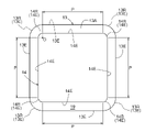
- At least the corner portion of the outer edge portion of the humidifying film is formed in an arc shape, and the width of the contact region at the corner portion is made equal to the width of the contact region at the plurality of parallel portions. It is preferable that the width of the close contact region is equal over the entire circumference of the humidifying film.
- the width between the outer edge of the protective film and the outer edge of the humidifying film can be made constant over the entire circumference, so that even if the humidifying film expands and contracts due to changes in the external environment, the protective film can be expanded and contracted. It can follow it and prevent the protective film from peeling off. Further, since the sealing material evenly adheres to the humidifying film and the protective film over the entire circumference, the humidifying film and the protective film are less likely to wrinkle.
- corner portion of the second outer edge portion of the protective film is formed in an arc shape.
- the width between the outer edge of the protective film and the outer edge of the humidifying film can be made constant over the entire circumference, so that even if the humidifying film expands and contracts due to changes in the external environment, the protective film can be expanded and contracted. It can follow it and prevent the protective film from peeling off. Further, since the sealing material evenly adheres to the humidifying film and the protective film over the entire circumference, the humidifying film and the protective film are less likely to wrinkle.
- the humidifier for a fuel cell (hereinafter referred to as "humidifier") according to the present invention is configured to protect and reinforce the humidifying film.
- the humidifier 1 of the present embodiment will be described.
- FIG. 1 is a perspective view of the humidifier 1 according to the first embodiment.
- FIG. 2 is a diagram showing a flow path communicating with the humidifier 1.
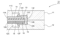
- FIG. 3 is a side sectional view of a part of the humidifying unit 10.
- the humidifier 1 includes a first plate 2, a second plate 3, and a humidifying unit 10.
- the humidifying unit 10 is provided so as to be sandwiched between the first plate 2 and the second plate 3. Although the details will be described later, the humidifying unit 10 gives the moisture contained in the water-containing air to the dry air to generate the humidified air. As shown in FIG.
- the humidifying unit 10 is configured with a first separator 11, a second separator 12, a humidifying film 13, and a protective film 14 laminated, and the humidifying unit 10 has a first plate 2 and a second plate 2.
- the second separator 12, the protective film 14, the humidifying film 13, the protective film 14, and the first separator 11 are laminated in this order between the plate 3 and the plate 3, and are provided in a state of being pressurized in the stacking direction.
- the humidifying unit 10 is configured by stacking a plurality of the humidifying units 10 in the state shown in FIG.
- a dry gas flow path 11C is formed in the central region of one surface.
- the first separator 11 is formed in a plate shape, and one surface corresponds to the front surface 11A of the front surface 11A and the back surface 11B on the surface of the plate-shaped first separator 11. Therefore, the central region of one surface corresponds to the region of the central portion when the first separator 11 is divided into the outer peripheral portion and the central portion in a plan view. Therefore, in the first separator 11, the dry gas flow path 11C is formed in the central region of the surface 11A in a plan view.
- the first separator 11 is provided with a sealing material 15 described later on the outer peripheral portion of the surface 11A in a plan view.
- the region where the sealing material 15 of the surface 11A is provided is defined as the outer peripheral portion, and the region where the dry gas flow path 11C is formed is described as the central portion in the plan view. do.
- the humidification unit 10 is provided with a plurality of first separators 11, and each dry gas flow path 11C is shown in FIG. As such, it is configured to communicate with the dry gas supply port 21 via the dry gas supply path 51 and the supply port 71. This makes it possible to introduce the dry air from the compressor 41 into the dry gas flow path 11C as described above.
- a dry gas flow path 11C or a water-containing gas flow path 12C may be formed in the central region of the back surface 11B.
- the humidifying film 13 is arranged between the dry gas flow path 11C and the water-containing gas flow path 12C in the stacking direction.
- the space between the dry gas flow path 11C and the water-containing gas flow path 12C is between the central region of the first separator 11 and the central region of the second separator 12 described above. Therefore, the humidifying film 13 is arranged between the central region of the first separator 11 and the central region of the second separator 12. That is, the dry gas flow path 11C and the water-containing gas flow path 12C face each other with the humidifying film 13 interposed therebetween.
- a plurality of humidifying films 13 are also provided in the humidifying unit 10.
- the humidifying film 13 fuels the dry gas supplied from the compressor 41 via the valve 42, the dry gas supply port 21, and the dry gas supply path 51 via the cathode off gas discharge path 43A and the water-containing gas supply port 31. Moisture contained in the water-containing gas flowing from the battery 43 is given to generate humidified air. Since the method of giving moisture to the dry air to generate a humidified gas (an example of "humidified air") is known, the description thereof is omitted here. The generated humidified gas is introduced into the cathode gas supply path 43B via the humidified air discharge path 52 and the humidified gas discharge port 22, and is supplied to the fuel cell 43.
- the protective film 14 is provided in a state of being laminated with the humidifying film 13 to reinforce the humidifying film 13.
- "Provided in a state of being laminated with the humidifying film 13" is provided in a state of being attached to at least one of the first surface 13A corresponding to the front surface of the humidifying film 13 and the second surface 13B corresponding to the back surface. Means to be.
- the protective film 14 is provided on both the first surface 13A and the second surface 13B (front and back) of the humidifying film 13, respectively.
- the protective film 14 for example, a non-woven fabric is used, but the protective film 14 is not limited to this, and papermaking, mesh, a porous film, or the like can be used. This makes it possible for the protective film 14 to protect the humidifying film 13 which is a thin film (for example, a thickness of several ⁇ m) and to reinforce the mechanical strength, for example, to improve the handleability in the manufacturing process and prevent damage. ..
- the outer edge portion (example of the second outer edge portion) 14E of at least one protective film 14 is closer to the central portion of the humidifying film 13 than the outer edge portion (example of the first outer edge portion) 13E of the humidifying film 13. It is installed in a retired state.
- the outer edge portion 14E of the protective film 14 is an edge portion (outer end portion) on the outer peripheral portion of the protective film 14 described above.
- the state of being retired to the central portion side of the humidifying film 13 means that the protective film 14 is provided in a state of being laminated on the humidifying film 13 in a plan view around the outer edge portion 14E of the protective film 14. It means that the humidifying film 13 is exposed.
- the outer peripheral length of the outer edge portion 14E of the protective film 14 is shorter than the outer peripheral length of the outer edge portion 13E of the humidifying film 13.
- the portion of the humidifying film 13 where the humidifying film 13 is exposed between the outer edge portion 13E of the humidifying film 13 and the outer edge portion 14E of the protective film 14 is referred to as an adhesion region 19.
- the protective film 14 is provided on both the first surface 13A and the second surface 13B of the humidifying film 13, but the first surface 13A and the second surface 13B of the humidifying film 13 are provided.
- the sealing material 15 is provided along the outer edge portion 13E of the humidifying film 13 with the humidifying film 13 and the protective film 14 sandwiched between them. Specifically, of the outer peripheral portion of one surface (surface 11A) of the first separator 11, a portion other than the dry gas supply path 51 and the humidified air discharge path 52 of the dry gas flow path 11C, and the second separator 12. Of the outer peripheral portion of one surface (surface 12A), it is provided over a portion other than the water-containing gas supply path 61 and the water-containing air discharge path 62 of the water-containing gas flow path 12C.
- the state in which the humidifying film 13 and the protective film 14 are sandwiched in the present embodiment means that the sealing material 15 is inserted between the protective film 14, the first separator 11, and the second separator 12, respectively, to protect the humidifying film 13 and the protective film 14.
- the supply port 71 of the dry gas flow path 11C communicates with the dry gas supply path 51, and a port for supplying the dry gas to the dry gas flow path 11C.
- the discharge port 72 corresponds to a port in which the humidified air is discharged from the dry gas flow path 11C in communication with the humidified air discharge path 52.
- the supply port 81 of the water-containing gas flow path 12C corresponds to a port in which the water-containing gas is supplied to the water-containing gas flow path 12C by communicating with the water-containing gas supply path 61.
- the discharge port 82 corresponds to a port that communicates with the water-containing air discharge path 62 and discharges the water-containing air from the water-containing gas flow path 12C.
- the humidifying film 13 and the protective film 14 are separated from each of the first separator 11 and the second separator 12, and the dry gas supply path 51, the humidified air discharge path 52, and the like. It is provided over the entire circumference in a portion other than the humidified gas supply path 61 and the humidified air discharge path 62.
- the sealing material 15 is shown in gray in FIG. As shown in FIG. 3, the outer edge of the sealing material 15 is provided so as to be flush with the outer edges of the first separator 11 and the second separator 12. In FIG. 2, the outer edge of the sealing material 15 is drawn so as to be slightly inside from the outer edges of the first separator 11 and the second separator 12, but they are actually flush with each other.
- an adhesive can be used for such a sealing material 15, for example, an adhesive can be used.
- the sealing material 15 is in direct contact with the humidifying film 13 in the adhesion region 19 of the humidifying film 13 between the outer edge portion 13E of the humidifying film 13 and the outer edge portion 14E of the protective film 14. It is provided in. As a result, even if the protective film 14 has voids along the thickness direction of the protective film 14, the airtightness between the sealing material 15 and the humidifying film 13 is enhanced, and the dry gas flow path 11C and the water content are contained. By sealing between the gas flow path 12C and the dry gas flow path 11C, it is possible to reduce the risk of air (dry air and humidified air) leakage (cross leak) from the dry gas flow path 11C to the water-containing gas flow path 12C.
- the close contact region 19 of the humidifying film 13 is provided on at least one of the first surface 13A corresponding to the front surface of the humidifying film 13 and the second surface 13B corresponding to the back surface.
- the protective film 14 is provided on both the first surface 13A and the second surface 13B of the humidifying film 13, but the adhesion region 19 is provided only on the second surface 13B.
- the dry air flowing through the dry gas flow path 11C is pressurized by the compressor 41, so that the pressure is higher than that of the water-containing air flowing through the water-containing gas flow path 12C.
- the close contact region 19 when the close contact region 19 is provided on the second surface 13B that receives the pressure of the dry air, it is between the dry air (high pressure) flowing through the dry gas flow path 11C and the water-containing air (low pressure) flowing through the water-containing gas flow path 12C. Even if there is a pressure difference between the two, the humidifying film 13 is suitable because it is difficult to bend and deform.
- the close contact region 19 may be provided on both the first surface 13A and the second surface 13B, or may be provided only on the first surface 13A.
- a supply port 71, a discharge port 72, a supply port 81, and a discharge port 82 are formed at the corners of the humidifying film 13 and the protective film 14, which are non-parallel (not marked with P). See also 2). Since the distance (width of the close contact region 19) in the plan view between the outer edge portion 13E of the humidifying film 13 provided with the sealing material 15 and the outer edge portion 14E of the protective film 14 is constant over the entire circumference, the external environment Even if the humidifying film 13 expands and contracts due to the change, the protective film 14 can follow it, and it is possible to prevent the protective film 14 and the humidifying film 13 from being damaged (for example, broken). Further, since the sealing material 15 evenly adheres to the humidifying film 13 and the protective film 14 over the entire circumference, the humidifying film 13 and the protective film 14 are less likely to wrinkle.
- At least the corner portion 13R of the outer edge portion 13E of the humidifying film 13 is formed in an arc shape in the humidifying film 13 in a plan view.
- a part of the corner portion 13R of the outer edge portion 13E of the humidifying film 13 does not overlap with the supply port 71, the discharge port 72, the supply port 81, and the discharge port 82, or the supply port 71, the discharge port 72, and the supply port
- the 81 and the discharge port 82 are formed at a place other than the corner portion 13R (the place where the reference numeral P is attached)
- the sealing material 15 is more easily provided at the corner portion 13R, so that the corner portion 13R is provided.
- the width of the close contact region 19 where the humidifying film 13 is exposed (the outer edge portion 13E of the humidifying film 13 and the protective film).
- the distance between the outer edge portion 14E of 14 and the outer edge portion 14E) covers the entire circumference of the humidifying film 13 and the protective film 14, including the supply port 71, the discharge port 72, the supply port 81, and the discharge port 82 (not shown in FIG. 4). It becomes possible to make it constant.
- the reinforcing member 16 is provided between the second separator 12 and the protective film 14 provided on the side of the first surface 13A of the humidifying film 13. That is, the reinforcing member 16 is laminated and arranged on the side opposite to the humidifying film 13 so as to face the protective film 14 provided on the first surface 13A side of the humidifying film 13.
- the reinforcing member 16 and the protective film 14 are arranged in contact with each other.
- the reinforcing member 16 has the same size as the humidifying film 13 and the facing (adjacent) protective film 14.
- the sealing material 15 is provided along the outer edge portion 13E of the humidifying film 13 with the humidifying film 13, the protective films 14 on both sides, and the reinforcing member 16 sandwiched therein.
- the state in which the humidifying film 13 and the protective films 14 on both sides and the reinforcing member 16 are sandwiched is between the protective film 14 on the second surface 13B side of the humidifying film 13 and the first separator 11 and for reinforcement.
- the protective film 14 provided on the side of the second surface 13B of the humidifying film 13 has the same size as the humidifying film 13 and is provided on the side of the first surface 13A of the humidifying film 13.
- the protective film 14 is provided in a retracted state on the central portion side of the humidifying film 13 so that the adhesion region 19 is provided only on the first surface 13A of the humidifying film 13, the first separator 11 and the humidifying film 13 are provided.
- a reinforcing member 16 having the same size as the protective film 14, that is, the same size as the humidifying film 13, may be provided between the protective film 14 on the second surface 13B side of the above.
- the sealing material 15 forms the corner portion 11F of the first separator 11 forming the dry gas flow path 11C and the water-containing gas flow path 12C. Covers the corner 12F of the second separator 12. As a result, the corner portions 11F and 12F can be caught and the protective film 14 and the reinforcing member 16 can be prevented from being torn.
- a wall 11D is formed on the outer edge of the first separator 11 and a wall 12D is formed on the outer edge of the second separator 12, so that the wall 11D and the wall 12D are brought into contact with each other.
- the sealing material 15 is provided so as to cover the corner portions 11F and 12F.
- the sealing material 15 can be prevented from leaking to the outside of the first separator 11 and the second separator 12, and the protective film 14 and the reinforcing member 16 can be prevented from being torn by the corner portions 11F and 12F.
- steps 11E and 12E are provided on the outer peripheral portion of the first separator 11 and the outer peripheral portion of the second separator 12, respectively, and the protective film 14 is provided on the step 11E and the reinforcing member 16 is provided on the step 12E.
- the humidifying film 13, the protective film 14, and the reinforcing member 16 can be easily positioned with respect to the first separator 11 and the second separator 12.
- the steps 11E and 12E of the above (3) are increased so that the sealing material 15 flows in, and the flowing sealing material 15 forms the dry gas flow path 11C. It covers the corner portion 11F of 11 and the corner portion 12F of the second separator 12 forming the water-containing gas flow path 12C. Further, a wall 11D is formed on the outer edge of the first separator 11 and a wall 12D is formed on the outer edge of the second separator 12, so that the wall 11D and the wall 12D are brought into contact with each other.
- the humidifying film 13 and the protective film 14 have been described as having a portion P parallel to each other, but the humidifying film 13 and the protective film 14 are configured not to have a portion P parallel to each other. It is also possible.
- the humidifying film 13 and the protective film 14 may have a triangular shape or a polygon having a pentagon or more. It may be configured by shape. Further, it may be configured in a circular shape.
- the surface 11A of the partition wall separating the dry gas flow paths 11C and 11C adjacent to the first separator 11 and the second separator 12 The surface 12A of the partition wall separating the adjacent water-containing gas flow paths 12C and 12C is in contact with the protective film 14 and the reinforcing member 16 (see FIGS. 3, 6 to 10), but the surfaces 11A and 12A of the partition wall are in contact with each other. At least one of the above may have a gap away from the protective film 14 and the reinforcing member 16. Thereby, the moisture of the gas flowing through the water-containing gas flow path 12C can be given to the dry air flowing through the dry gas flow path 11C even at the portion facing the surfaces 11A and 12A of the partition wall.
- the present invention can be used for a humidifier for a fuel cell provided with a humidifying unit that generates humidified air by giving moisture contained in hydrous air to dry air.
Landscapes
- Chemical & Material Sciences (AREA)
- Chemical Kinetics & Catalysis (AREA)
- Life Sciences & Earth Sciences (AREA)
- Engineering & Computer Science (AREA)
- Manufacturing & Machinery (AREA)
- Sustainable Development (AREA)
- Sustainable Energy (AREA)
- Electrochemistry (AREA)
- General Chemical & Material Sciences (AREA)
- Fuel Cell (AREA)
Priority Applications (4)
| Application Number | Priority Date | Filing Date | Title |
|---|---|---|---|
| JP2022565464A JP7425424B2 (ja) | 2020-11-26 | 2021-11-26 | 燃料電池用加湿器 |
| EP21898119.9A EP4254570A4 (en) | 2020-11-26 | 2021-11-26 | HUMIDIFIER FOR A FUEL CELL |
| US18/249,276 US20230395828A1 (en) | 2020-11-26 | 2021-11-26 | Humidifier for fuel cell |
| CN202180075979.7A CN116438688A (zh) | 2020-11-26 | 2021-11-26 | 燃料电池用加湿器 |
Applications Claiming Priority (2)
| Application Number | Priority Date | Filing Date | Title |
|---|---|---|---|
| JP2020-195803 | 2020-11-26 | ||
| JP2020195803 | 2020-11-26 |
Publications (1)
| Publication Number | Publication Date |
|---|---|
| WO2022114147A1 true WO2022114147A1 (ja) | 2022-06-02 |
Family
ID=81754453
Family Applications (1)
| Application Number | Title | Priority Date | Filing Date |
|---|---|---|---|
| PCT/JP2021/043473 Ceased WO2022114147A1 (ja) | 2020-11-26 | 2021-11-26 | 燃料電池用加湿器 |
Country Status (5)
| Country | Link |
|---|---|
| US (1) | US20230395828A1 (https=) |
| EP (1) | EP4254570A4 (https=) |
| JP (1) | JP7425424B2 (https=) |
| CN (1) | CN116438688A (https=) |
| WO (1) | WO2022114147A1 (https=) |
Citations (4)
| Publication number | Priority date | Publication date | Assignee | Title |
|---|---|---|---|---|
| JP2003187839A (ja) | 2001-12-17 | 2003-07-04 | Aisin Seiki Co Ltd | 燃料電池用加湿器 |
| JP2008282555A (ja) * | 2007-05-08 | 2008-11-20 | Matsushita Electric Ind Co Ltd | 燃料電池装置 |
| JP2009199741A (ja) * | 2008-02-19 | 2009-09-03 | Toyota Motor Corp | 燃料電池及び加湿器 |
| DE202016100670U1 (de) * | 2016-02-10 | 2017-05-11 | Reinz-Dichtungs-Gmbh | Strömungsplatte für einen Befeuchter |
Family Cites Families (5)
| Publication number | Priority date | Publication date | Assignee | Title |
|---|---|---|---|---|
| JP4062198B2 (ja) | 2003-07-30 | 2008-03-19 | トヨタ自動車株式会社 | 燃料電池の加湿装置 |
| JP2006156099A (ja) * | 2004-11-29 | 2006-06-15 | Mitsubishi Electric Corp | 加湿器およびその製造方法 |
| JP4542029B2 (ja) | 2005-12-14 | 2010-09-08 | 三菱電機株式会社 | 加湿器 |
| US9553327B2 (en) | 2014-12-30 | 2017-01-24 | GM Global Technology Operations LLC | Grafted functional groups on expanded tetrafluoroethylene (ePTFE) support for fuel cell and water transport membranes |
| CN211265624U (zh) * | 2019-01-30 | 2020-08-14 | 深圳伊腾迪新能源有限公司 | 一种新型燃料电池气体增湿器 |
-
2021
- 2021-11-26 JP JP2022565464A patent/JP7425424B2/ja active Active
- 2021-11-26 CN CN202180075979.7A patent/CN116438688A/zh active Pending
- 2021-11-26 US US18/249,276 patent/US20230395828A1/en active Pending
- 2021-11-26 WO PCT/JP2021/043473 patent/WO2022114147A1/ja not_active Ceased
- 2021-11-26 EP EP21898119.9A patent/EP4254570A4/en active Pending
Patent Citations (4)
| Publication number | Priority date | Publication date | Assignee | Title |
|---|---|---|---|---|
| JP2003187839A (ja) | 2001-12-17 | 2003-07-04 | Aisin Seiki Co Ltd | 燃料電池用加湿器 |
| JP2008282555A (ja) * | 2007-05-08 | 2008-11-20 | Matsushita Electric Ind Co Ltd | 燃料電池装置 |
| JP2009199741A (ja) * | 2008-02-19 | 2009-09-03 | Toyota Motor Corp | 燃料電池及び加湿器 |
| DE202016100670U1 (de) * | 2016-02-10 | 2017-05-11 | Reinz-Dichtungs-Gmbh | Strömungsplatte für einen Befeuchter |
Non-Patent Citations (1)
| Title |
|---|
| See also references of EP4254570A4 |
Also Published As
| Publication number | Publication date |
|---|---|
| JP7425424B2 (ja) | 2024-01-31 |
| EP4254570A1 (en) | 2023-10-04 |
| CN116438688A (zh) | 2023-07-14 |
| EP4254570A4 (en) | 2024-05-01 |
| JPWO2022114147A1 (https=) | 2022-06-02 |
| US20230395828A1 (en) | 2023-12-07 |
Similar Documents
| Publication | Publication Date | Title |
|---|---|---|
| JP7022023B2 (ja) | 発電セル | |
| US20120034542A1 (en) | Seal for solid polymer electrolyte fuel cell | |
| JP6914980B2 (ja) | 枠付き電解質膜・電極構造体及び燃料電池 | |
| MXPA06011687A (es) | Distribucion de gas de celda de combustible. | |
| JP2019533282A (ja) | 加湿器の流動板 | |
| JP5087863B2 (ja) | 燃料電池 | |
| EP4266435A1 (en) | Fuel cell membrane humidifier | |
| JP7425424B2 (ja) | 燃料電池用加湿器 | |
| JP6663901B2 (ja) | 燃料電池 | |
| JP6843730B2 (ja) | 燃料電池及びその運転方法 | |
| CN115621501A (zh) | 膜加湿器 | |
| JP5928403B2 (ja) | 燃料電池のセル構造 | |
| KR20250042072A (ko) | 가습기 | |
| JP3963716B2 (ja) | 燃料電池スタック | |
| JP2012069445A (ja) | 燃料電池 | |
| JP5549578B2 (ja) | 燃料電池 | |
| CN110600760A (zh) | 燃料电池单元及燃料电池组 | |
| JP4896813B2 (ja) | 燃料電池用加湿装置 | |
| JP5137478B2 (ja) | 燃料電池 | |
| JP2024048080A (ja) | 燃料電池用加湿器 | |
| JP2024052033A (ja) | 燃料電池用加湿器 | |
| CN216850016U (zh) | 加湿器 | |
| JP3201201B2 (ja) | 積層リン酸型燃料電池 | |
| KR20250001272A (ko) | 복수 개의 가습 모듈이 병렬 연결된 연료전지용 막가습기 | |
| JP2023161523A (ja) | 燃料電池スタック |
Legal Events
| Date | Code | Title | Description |
|---|---|---|---|
| 121 | Ep: the epo has been informed by wipo that ep was designated in this application |
Ref document number: 21898119 Country of ref document: EP Kind code of ref document: A1 |
|
| ENP | Entry into the national phase |
Ref document number: 2022565464 Country of ref document: JP Kind code of ref document: A |
|
| NENP | Non-entry into the national phase |
Ref country code: DE |
|
| ENP | Entry into the national phase |
Ref document number: 2021898119 Country of ref document: EP Effective date: 20230626 |