WO2022106950A1 - グラフェン、電極、二次電池、車両および電子機器 - Google Patents
グラフェン、電極、二次電池、車両および電子機器 Download PDFInfo
- Publication number
- WO2022106950A1 WO2022106950A1 PCT/IB2021/060243 IB2021060243W WO2022106950A1 WO 2022106950 A1 WO2022106950 A1 WO 2022106950A1 IB 2021060243 W IB2021060243 W IB 2021060243W WO 2022106950 A1 WO2022106950 A1 WO 2022106950A1
- Authority
- WO
- WIPO (PCT)
- Prior art keywords
- secondary battery
- active material
- graphene
- positive electrode
- lithium
- Prior art date
- Legal status (The legal status is an assumption and is not a legal conclusion. Google has not performed a legal analysis and makes no representation as to the accuracy of the status listed.)
- Ceased
Links
Images


Classifications
-
- H—ELECTRICITY
- H01—ELECTRIC ELEMENTS
- H01M—PROCESSES OR MEANS, e.g. BATTERIES, FOR THE DIRECT CONVERSION OF CHEMICAL ENERGY INTO ELECTRICAL ENERGY
- H01M4/00—Electrodes
- H01M4/02—Electrodes composed of, or comprising, active material
- H01M4/36—Selection of substances as active materials, active masses, active liquids
- H01M4/58—Selection of substances as active materials, active masses, active liquids of inorganic compounds other than oxides or hydroxides, e.g. sulfides, selenides, tellurides, halogenides or LiCoFy; of polyanionic structures, e.g. phosphates, silicates or borates
- H01M4/583—Carbonaceous material, e.g. graphite-intercalation compounds or CFx
- H01M4/5835—Comprising fluorine or fluoride salts
-
- C—CHEMISTRY; METALLURGY
- C01—INORGANIC CHEMISTRY
- C01B—NON-METALLIC ELEMENTS; COMPOUNDS THEREOF; METALLOIDS OR COMPOUNDS THEREOF NOT COVERED BY SUBCLASS C01C
- C01B32/00—Carbon; Compounds thereof
- C01B32/15—Nano-sized carbon materials
- C01B32/182—Graphene
-
- C—CHEMISTRY; METALLURGY
- C01—INORGANIC CHEMISTRY
- C01B—NON-METALLIC ELEMENTS; COMPOUNDS THEREOF; METALLOIDS OR COMPOUNDS THEREOF NOT COVERED BY SUBCLASS C01C
- C01B32/00—Carbon; Compounds thereof
- C01B32/15—Nano-sized carbon materials
- C01B32/182—Graphene
- C01B32/194—After-treatment
-
- H—ELECTRICITY
- H01—ELECTRIC ELEMENTS
- H01M—PROCESSES OR MEANS, e.g. BATTERIES, FOR THE DIRECT CONVERSION OF CHEMICAL ENERGY INTO ELECTRICAL ENERGY
- H01M10/00—Secondary cells; Manufacture thereof
- H01M10/05—Accumulators with non-aqueous electrolyte
- H01M10/052—Li-accumulators
-
- H—ELECTRICITY
- H01—ELECTRIC ELEMENTS
- H01M—PROCESSES OR MEANS, e.g. BATTERIES, FOR THE DIRECT CONVERSION OF CHEMICAL ENERGY INTO ELECTRICAL ENERGY
- H01M10/00—Secondary cells; Manufacture thereof
- H01M10/05—Accumulators with non-aqueous electrolyte
- H01M10/052—Li-accumulators
- H01M10/0525—Rocking-chair batteries, i.e. batteries with lithium insertion or intercalation in both electrodes; Lithium-ion batteries
-
- H—ELECTRICITY
- H01—ELECTRIC ELEMENTS
- H01M—PROCESSES OR MEANS, e.g. BATTERIES, FOR THE DIRECT CONVERSION OF CHEMICAL ENERGY INTO ELECTRICAL ENERGY
- H01M4/00—Electrodes
- H01M4/02—Electrodes composed of, or comprising, active material
- H01M4/13—Electrodes for accumulators with non-aqueous electrolyte, e.g. for lithium-accumulators; Processes of manufacture thereof
- H01M4/133—Electrodes based on carbonaceous material, e.g. graphite-intercalation compounds or CFx
-
- H—ELECTRICITY
- H01—ELECTRIC ELEMENTS
- H01M—PROCESSES OR MEANS, e.g. BATTERIES, FOR THE DIRECT CONVERSION OF CHEMICAL ENERGY INTO ELECTRICAL ENERGY
- H01M4/00—Electrodes
- H01M4/02—Electrodes composed of, or comprising, active material
- H01M4/36—Selection of substances as active materials, active masses, active liquids
- H01M4/362—Composites
- H01M4/366—Composites as layered products
-
- H—ELECTRICITY
- H01—ELECTRIC ELEMENTS
- H01M—PROCESSES OR MEANS, e.g. BATTERIES, FOR THE DIRECT CONVERSION OF CHEMICAL ENERGY INTO ELECTRICAL ENERGY
- H01M4/00—Electrodes
- H01M4/02—Electrodes composed of, or comprising, active material
- H01M4/36—Selection of substances as active materials, active masses, active liquids
- H01M4/58—Selection of substances as active materials, active masses, active liquids of inorganic compounds other than oxides or hydroxides, e.g. sulfides, selenides, tellurides, halogenides or LiCoFy; of polyanionic structures, e.g. phosphates, silicates or borates
- H01M4/583—Carbonaceous material, e.g. graphite-intercalation compounds or CFx
- H01M4/587—Carbonaceous material, e.g. graphite-intercalation compounds or CFx for inserting or intercalating light metals
-
- H—ELECTRICITY
- H01—ELECTRIC ELEMENTS
- H01M—PROCESSES OR MEANS, e.g. BATTERIES, FOR THE DIRECT CONVERSION OF CHEMICAL ENERGY INTO ELECTRICAL ENERGY
- H01M4/00—Electrodes
- H01M4/02—Electrodes composed of, or comprising, active material
- H01M4/62—Selection of inactive substances as ingredients for active masses, e.g. binders, fillers
- H01M4/624—Electric conductive fillers
- H01M4/625—Carbon or graphite
-
- C—CHEMISTRY; METALLURGY
- C01—INORGANIC CHEMISTRY
- C01B—NON-METALLIC ELEMENTS; COMPOUNDS THEREOF; METALLOIDS OR COMPOUNDS THEREOF NOT COVERED BY SUBCLASS C01C
- C01B2204/00—Structure or properties of graphene
- C01B2204/20—Graphene characterized by its properties
- C01B2204/22—Electronic properties
-
- C—CHEMISTRY; METALLURGY
- C01—INORGANIC CHEMISTRY
- C01P—INDEXING SCHEME RELATING TO STRUCTURAL AND PHYSICAL ASPECTS OF SOLID INORGANIC COMPOUNDS
- C01P2002/00—Crystal-structural characteristics
- C01P2002/01—Crystal-structural characteristics depicted by a TEM-image
-
- C—CHEMISTRY; METALLURGY
- C01—INORGANIC CHEMISTRY
- C01P—INDEXING SCHEME RELATING TO STRUCTURAL AND PHYSICAL ASPECTS OF SOLID INORGANIC COMPOUNDS
- C01P2002/00—Crystal-structural characteristics
- C01P2002/80—Crystal-structural characteristics defined by measured data other than those specified in group C01P2002/70
- C01P2002/82—Crystal-structural characteristics defined by measured data other than those specified in group C01P2002/70 by IR- or Raman-data
-
- C—CHEMISTRY; METALLURGY
- C01—INORGANIC CHEMISTRY
- C01P—INDEXING SCHEME RELATING TO STRUCTURAL AND PHYSICAL ASPECTS OF SOLID INORGANIC COMPOUNDS
- C01P2002/00—Crystal-structural characteristics
- C01P2002/80—Crystal-structural characteristics defined by measured data other than those specified in group C01P2002/70
- C01P2002/85—Crystal-structural characteristics defined by measured data other than those specified in group C01P2002/70 by XPS, EDX or EDAX data
-
- C—CHEMISTRY; METALLURGY
- C01—INORGANIC CHEMISTRY
- C01P—INDEXING SCHEME RELATING TO STRUCTURAL AND PHYSICAL ASPECTS OF SOLID INORGANIC COMPOUNDS
- C01P2004/00—Particle morphology
- C01P2004/01—Particle morphology depicted by an image
- C01P2004/04—Particle morphology depicted by an image obtained by TEM, STEM, STM or AFM
-
- C—CHEMISTRY; METALLURGY
- C01—INORGANIC CHEMISTRY
- C01P—INDEXING SCHEME RELATING TO STRUCTURAL AND PHYSICAL ASPECTS OF SOLID INORGANIC COMPOUNDS
- C01P2006/00—Physical properties of inorganic compounds
- C01P2006/40—Electric properties
-
- H—ELECTRICITY
- H01—ELECTRIC ELEMENTS
- H01M—PROCESSES OR MEANS, e.g. BATTERIES, FOR THE DIRECT CONVERSION OF CHEMICAL ENERGY INTO ELECTRICAL ENERGY
- H01M2220/00—Batteries for particular applications
- H01M2220/20—Batteries in motive systems, e.g. vehicle, ship, plane
-
- Y—GENERAL TAGGING OF NEW TECHNOLOGICAL DEVELOPMENTS; GENERAL TAGGING OF CROSS-SECTIONAL TECHNOLOGIES SPANNING OVER SEVERAL SECTIONS OF THE IPC; TECHNICAL SUBJECTS COVERED BY FORMER USPC CROSS-REFERENCE ART COLLECTIONS [XRACs] AND DIGESTS
- Y02—TECHNOLOGIES OR APPLICATIONS FOR MITIGATION OR ADAPTATION AGAINST CLIMATE CHANGE
- Y02E—REDUCTION OF GREENHOUSE GAS [GHG] EMISSIONS, RELATED TO ENERGY GENERATION, TRANSMISSION OR DISTRIBUTION
- Y02E60/00—Enabling technologies; Technologies with a potential or indirect contribution to GHG emissions mitigation
- Y02E60/10—Energy storage using batteries
Definitions
- the present invention relates to a secondary battery using a positive electrode active material and a method for producing the same.
- the present invention relates to a secondary battery using graphene and a method for producing the same.
- the present invention relates to electronic devices such as personal digital assistants having a secondary battery, vehicles, and the like.
- the uniform state of the present invention relates to a product, a method, or a manufacturing method.
- the invention relates to a process, machine, manufacture, or composition (composition of matter).
- One aspect of the present invention relates to a semiconductor device, a display device, a light emitting device, a power storage device, a lighting device, an electronic device, or a method for manufacturing the same.
- the electronic device refers to all the devices having a power storage device, and the electro-optical device having the power storage device, the information terminal device having the power storage device, and the like are all electronic devices.
- a power storage device refers to an element and a device having a power storage function in general.
- a power storage device also referred to as a secondary battery
- a lithium ion secondary battery such as a lithium ion secondary battery, a lithium ion capacitor, an electric double layer capacitor, and the like.
- lithium-ion secondary batteries with high output and high energy density are mobile information terminals such as mobile phones, smartphones, or notebook computers, portable music players, digital cameras, medical devices, hybrid vehicles (HVs), and electricity.
- HVs hybrid vehicles
- EVs electric vehicles
- PSVs plug-in hybrid vehicles
- Non-Patent Document 1 Japanese Patent Document 1
- Patent Document 1 In order to improve the cycle characteristics and increase the capacity of the lithium ion secondary battery, improvement of the negative electrode having a coating film is being studied (Patent Document 1).
- Non-Patent Document 2 describes the reaction of a compound having fluorine.
- Silicon-based materials have a high capacity and are used as active materials for secondary batteries.
- the silicon material can be characterized by the chemical shift value obtained from the NMR spectrum (Patent Document 2).
- One aspect of the present invention is to provide a novel graphene.
- one aspect of the present invention is to provide a novel graphene compound.
- one aspect of the present invention is to provide an electrode having a high output.
- one aspect of the present invention is to provide a novel electrode.
- one aspect of the present invention is to provide a novel method for producing graphene.
- one aspect of the present invention is to provide a novel method for producing a graphene compound.
- one aspect of the present invention is to provide a novel method for manufacturing an electrode.
- one aspect of the present invention is to provide a secondary battery with less deterioration.
- one aspect of the present invention is to provide a highly safe secondary battery.
- one aspect of the present invention is to provide a novel secondary battery.
- one aspect of the present invention is to provide a novel substance, active material particles, a secondary battery, a power storage device, or a method for producing them.
- One aspect of the present invention is graphene having a hole composed of a multi-membered ring having 9 or more membered rings composed of carbon atoms.
- one or more of the carbon atoms constituting the multi-membered ring are terminated by fluorine.
- one embodiment of the present invention comprises active material particles and graphene, in which graphene has pores composed of 9 or more membered rings composed of carbon atoms, and graphene is active.
- An electrode that covers at least a portion of the surface of a material particle.
- one or more of the carbon atoms constituting the multi-membered ring are terminated by fluorine.
- graphene has a first peak observed at or near 1580 cm -1 and a second peak observed at or near 1360 cm -1 in Raman spectroscopy analysis. Is preferable.
- the active material particles are preferably positive electrode active material particles.
- the active material particles are preferably negative electrode active material particles.
- one aspect of the present invention is a secondary battery having the electrode and the electrolyte according to any one of the above.
- one aspect of the present invention is an electronic device having the secondary battery described above.
- one aspect of the present invention is a vehicle having the secondary battery described above.
- a novel graphene can be provided. Further, according to one aspect of the present invention, a novel graphene compound can be provided. Further, according to one aspect of the present invention, it is possible to provide an electrode having a high output. Further, according to one aspect of the present invention, a novel electrode can be provided.
- a secondary battery with less deterioration. Further, according to one aspect of the present invention, it is possible to provide a highly safe secondary battery. Further, according to one aspect of the present invention, a novel secondary battery can be provided.
- FIG. 1A, 1B and 1C are views showing an example of a cross section of an electrode.
- 2A and 2B are views showing an example of a cross section of an electrode.
- FIG. 3 is a diagram illustrating the crystal structure of the positive electrode active material.
- FIG. 4 is a diagram illustrating the crystal structure of the positive electrode active material.
- FIG. 5 is a phase diagram.
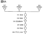
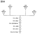
- 6A and 6B are views showing an example of a manufacturing method.
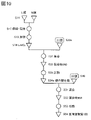
- FIG. 7 is a diagram showing an example of a method for manufacturing an electrode according to an aspect of the present invention.
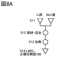
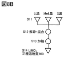
- 8A and 8B are diagrams illustrating an example of a method for producing a positive electrode active material according to one aspect of the present invention.
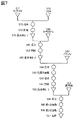
- FIG. 9 is a diagram illustrating an example of a method for producing a positive electrode active material according to one aspect of the present invention.
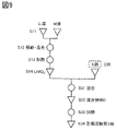
- FIG. 10 is a diagram illustrating an example of a method for producing a positive electrode active material according to one aspect of the present invention.
- FIG. 11 is a diagram illustrating an example of a method for producing a positive electrode active material according to one aspect of the present invention.
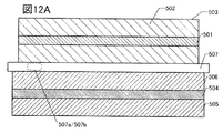
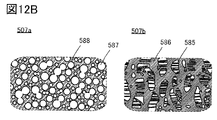
- 12A and 12B are examples of cross-sectional views of the secondary battery.
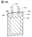
- 13A and 13B are views showing an example of the appearance of the secondary battery.
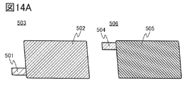
- 14A and 14B are diagrams illustrating a method for manufacturing a secondary battery.
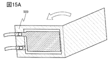
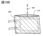
- 15A and 15B are diagrams illustrating a method for manufacturing a secondary battery.
- FIG. 16 is a diagram showing an example of the appearance of the secondary battery.
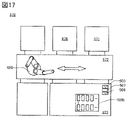
- FIG. 17 is a top view showing an example of a secondary battery manufacturing apparatus.
- FIG. 18 is a cross-sectional view showing an example of a method for manufacturing a secondary battery.
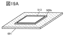
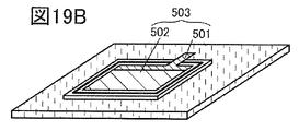
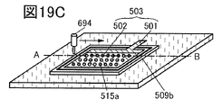
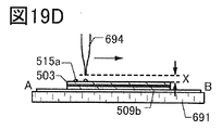
- 19A to 19C are perspective views showing an example of a method for manufacturing a secondary battery.
- FIG. 19D is a cross-sectional view corresponding to FIG. 19C.
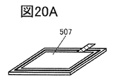
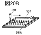
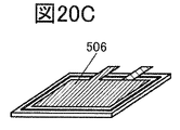
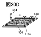
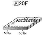
- 20A to 20F are perspective views showing an example of a method for manufacturing a secondary battery.
- FIG. 21 is a cross-sectional view showing an example of a secondary battery.
- FIG. 22A is a diagram showing an example of a secondary battery.
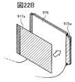
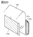
- 22B and 22C are views showing an example of a method for producing a laminated body.
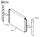
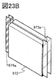
- 23A to 23C are diagrams showing an example of a method for manufacturing a secondary battery.
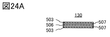
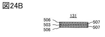
- FIG. 24A and 24B are cross-sectional views showing an example of the laminated body.
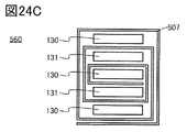
- FIG. 24C is a cross-sectional view showing an example of a secondary battery.
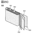
- 25A and 25B are diagrams showing an example of a secondary battery.
- FIG. 25C is a diagram showing the inside of the secondary battery.
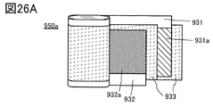
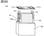
- 26A to 26C are views showing an example of a secondary battery.
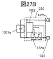
- FIG. 27A is a perspective view showing an example of a battery pack.
- FIG. 27B is a block diagram showing an example of a battery pack.
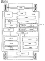
- FIG. 27C is a block diagram showing an example of a vehicle having a motor.
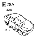
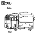
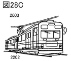
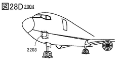
- 28A to 28E are views showing an example of a transportation vehicle.
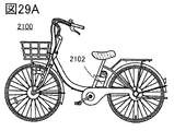
- 29A is a diagram showing an electric bicycle, FIG.
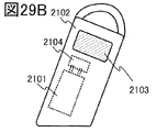
- FIG. 29B is a diagram showing a secondary battery of the electric bicycle
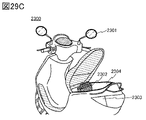
- FIG. 29C is a diagram illustrating an electric motorcycle.
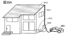
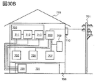
- 30A and 30B are diagrams showing an example of a power storage device.
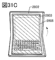
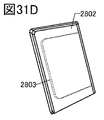
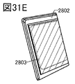
- 31A to 31E are diagrams showing an example of an electronic device.
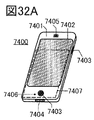
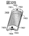
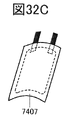
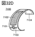
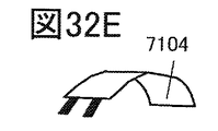
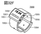
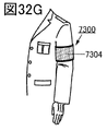
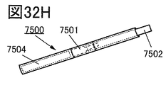
- 32A to 32H are diagrams illustrating an example of an electronic device.
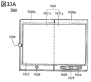
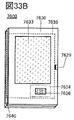
- 33A to 33C are diagrams illustrating an example of an electronic device.
- FIG. 34 is a diagram illustrating an example of an electronic device.
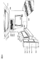
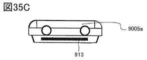
- 35A to 35C are diagrams illustrating an example of an electronic device.
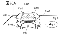
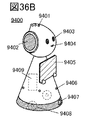
- 36A to 36C are views showing an example of an electronic device.
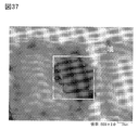
- FIG. 37 is an optical micrograph.
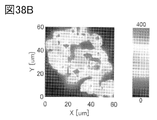
- 38A, 38B and 38C are the evaluation results of Raman spectroscopy.
- FIG. 39 is a Raman spectrum.
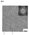
- FIG. 40 is a TEM image.
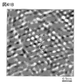
- 41A and 41B are FFT filtering images of TEM images.
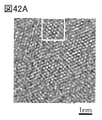
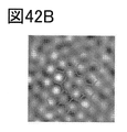
- 42A and 42B are FFT filtering images of TEM images.
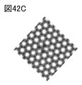
- FIG. 42C is a TEM image obtained by calculation.
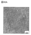
- FIG. 43A is an STEM image.
- FIG. 43B is an EDX analysis result.
- the crystal plane and the direction are indicated by the Miller index.
- the notation of the crystal plane and direction is to add a bar to the number, but in the present specification etc., due to the limitation of the application notation, instead of adding a bar to the number,-(minus) before the number. It may be expressed with a code).
- the individual orientation indicating the direction in the crystal is []
- the aggregate orientation indicating all equivalent directions is ⁇ >
- the individual plane indicating the crystal plane is ()
- the aggregate plane having equivalent symmetry is ⁇ . Express each with.
- segregation refers to a phenomenon in which a certain element (for example, B) is spatially unevenly distributed in a solid composed of a plurality of elements (for example, A, B, C).
- the surface layer portion of particles such as active substances is, for example, a region preferably within 50 nm, more preferably within 35 nm, still more preferably within 20 nm from the surface.
- the surface created by cracks and cracks can also be called the surface.
- the area deeper than the surface layer is called the inside.
- the charging depth when all the lithium that can be inserted and removed is inserted into the positive electrode active material is 0, and the charging depth when all the lithium that can be inserted and removed from the positive electrode active material is removed. Is set to 1.
- charging means moving lithium ions from the positive electrode to the negative electrode in the battery and moving electrons from the positive electrode to the negative electrode in an external circuit.
- the positive electrode active material the release of lithium ions is called charging.
- a positive electrode active material having a charging depth of 0.7 or more and 0.9 or less may be referred to as a positive electrode active material charged at a high voltage.
- discharging means moving lithium ions from the negative electrode to the positive electrode in the battery and moving electrons from the negative electrode to the positive electrode in an external circuit.
- inserting lithium ions is called electric discharge.
- a positive electrode active material having a charging depth of 0.06 or less, or a positive electrode active material in which 90% or more of the charging capacity is discharged from a state of being charged at a high voltage is defined as a sufficiently discharged positive electrode active material. ..
- a non-equilibrium phase change means a phenomenon that causes a non-linear change in a physical quantity.
- an unbalanced phase change occurs before and after the peak in the dQ / dV curve obtained by differentiating the capacitance (Q) with the voltage (V) (dQ / dV), and the crystal structure changes significantly. ..
- the secondary battery has, for example, a positive electrode and a negative electrode.
- a positive electrode active material As a material constituting the positive electrode, there is a positive electrode active material.
- the positive electrode active material is, for example, a substance that undergoes a reaction that contributes to the charge / discharge capacity.
- the positive electrode active material may contain a substance that does not contribute to the charge / discharge capacity as a part thereof.
- the positive electrode active material of one aspect of the present invention may be expressed as a positive electrode material, a positive electrode material for a secondary battery, or the like. Further, in the present specification and the like, it is preferable that the positive electrode active material of one aspect of the present invention has a compound. Further, in the present specification and the like, it is preferable that the positive electrode active material of one aspect of the present invention has a composition. Further, in the present specification and the like, it is preferable that the positive electrode active material of one aspect of the present invention has a complex.
- the discharge rate is the relative ratio of the current at the time of discharge to the battery capacity, and is expressed in the unit C.
- the current corresponding to 1C is X (A).
- X (A) When discharged with a current of 2X (A), it is said to be discharged at 2C, and when discharged with a current of X / 5 (A), it is said to be discharged at 0.2C.
- the charging rate is also the same.
- When charged with a current of 2X (A) it is said to be charged with 2C, and when charged with a current of X / 5 (A), it is charged with 0.2C. It is said that it was.
- Constant current charging refers to, for example, a method of charging with a constant charging rate.
- Constant voltage charging refers to, for example, a method of charging by keeping the voltage constant when the charging reaches the upper limit voltage.
- the constant current discharge refers to, for example, a method of discharging with a constant discharge rate.
- the graphene of one aspect of the present invention has a hole composed of a multi-membered ring composed of carbon.
- the multi-membered ring is preferably 9-membered or more.
- examples of a multi-membered ring having 9 or more members include a 12-membered ring, an 18-membered ring, and a 22-membered ring.
- the pores of graphene according to one aspect of the present invention cause a eutectic reaction between a material that becomes graphene as a first material, a compound having a halogen as a second material, and a second material as a third material. It is preferably provided by mixing the compound and heating.
- graphene oxide can be used as the material to be graphene.
- the graphene according to one aspect of the present invention preferably has a halogen. It is preferable that one or more of the carbons constituting the multi-membered ring are terminated by a halogen atom. Fluorine is particularly preferable as the halogen.
- the graphene according to one aspect of the present invention preferably has a functional group.
- the functional group of graphene in one aspect of the present invention include a hydroxy group, an epoxy group and a carboxy group.
- the functional group of the graphene of one aspect of the present invention may be bonded to the carbon constituting the multi-membered ring of the graphene of the present invention.
- the graphene of one aspect of the present invention has a sheet-like shape.
- Graphene has a two-dimensional structure formed by a 6-membered carbon ring. It can be rephrased that graphene is a sheet having a two-dimensional structure formed of a carbon 6-membered ring, and the graphene of one aspect of the present invention is composed of a carbon multi-membered ring as a part of the sheet. Has a hole to be made.
- the electrode of one aspect of the present invention has active material particles and graphene.
- Graphene preferably covers at least a portion of the surface of the active material particles.
- the electrode of one aspect of the present invention has active material particles and a plurality of graphenes. At least a part of the surface of the active material particles may be covered with a plurality of graphenes.
- the plurality of graphenes may have a region that overlaps with each other and a region that does not overlap with each other. By stacking a part of a plurality of graphenes on each other, a sheet having a larger area can be formed.
- the first graphene has a first region that overlaps the active material particles and the second graphene. The first region is located on the surface of the active material particles. The first region is sandwiched between the active material particles and the second graphene.
- the first graphene and a part of the second graphene can be overlapped with each other.
- the first graphene and the second graphene may have a bond in a region where they overlap each other.
- they may be attracted by intramolecular force.
- Graphene is provided so as to cling to the surface of the active material particles. Further, graphene preferably has a region in which it comes into surface contact with the active material particles. Further, graphene is preferably provided so as to adhere to the surface of the active material.
- the electrode of one aspect of the present invention has a plurality of active material particles and graphene.
- Graphene preferably covers at least a portion of each of the surfaces of the active material.
- Graphene is also preferably clinging across a plurality of active material particles.
- the electrode of one aspect of the present invention has a plurality of active material particles and a plurality of graphene.
- a plurality of graphenes By having a plurality of graphenes overlapping each other, it is possible to form a sheet having a larger area.
- the sheet preferably covers at least a portion of each of the surfaces of the plurality of active material particles. Further, it is preferable that the sheet clings to a plurality of active substances.
- graphene forms a bag-shaped region.
- the bag-shaped area may be composed of a plurality of graphenes.
- a plurality of graphenes can form a bag-like region by having regions that overlap each other.
- the plurality of active material particles are encapsulated in a bag-shaped region.
- a plurality of graphenes can form a three-dimensional conductive path. Further, in the electrode of one aspect of the present invention, a plurality of graphenes may form a three-dimensional network structure.
- the electrode of one aspect of the present invention has, for example, a current collector and an active material layer.
- the active material layer is provided on the current collector.
- the active material layer has an active material and graphene. Further, the active material layer may have a binder.
- a sheet-like shape, a net-like shape, a punching metal-like shape, an expanded metal-like shape, or the like can be appropriately used. It is preferable to use a current collector having a thickness of 10 ⁇ m or more and 30 ⁇ m or less.
- the current collector used for the negative electrode it is preferable to use a material that does not alloy with carrier ions such as lithium.
- a titanium compound may be provided by laminating on the metal element shown above.
- titanium compounds include titanium nitride, titanium oxide, titanium nitride in which a part of nitrogen is replaced with oxygen, titanium oxide in which a part of oxygen is replaced with nitrogen, and titanium oxide (TIO z N w , 0 ⁇ z. One selected from ⁇ 2, 0 ⁇ w ⁇ 1), or two or more thereof can be mixed or laminated and used.
- titanium nitride is particularly preferable because it has high conductivity and a high function of suppressing oxidation.
- the active material layer contains a compound having oxygen
- the oxidation reaction between the metal element and oxygen can be suppressed.
- the active material layer contains a compound having oxygen
- the oxidation reaction between the metal element and oxygen can be suppressed.
- the active material layer contains a compound having oxygen
- the oxidation reaction between the metal element and oxygen can be suppressed.
- the strength of the active material layer can be increased by distributing a plurality of graphenes in the electrode so as to spread three-dimensionally and cover the active material.
- the strength of the active material layer for example, the collapse of the active material layer can be suppressed.
- peeling of the active material layer from the current collector can be suppressed by contacting a part of each of the graphenes with the current collector.
- Graphene may function as a conductive agent that imparts a conductive path in the electrode, and may also function as a binder that enhances the strength of the active material layer and the electrode.
- a three-dimensional conductive path can be formed by binding a plurality of graphenes to each other.
- the three-dimensional conductive path formed by bonding a plurality of graphenes in this way is hereinafter referred to as a graphene net.
- the graphene net can also function as a binder for binding the active materials to each other. Therefore, since the amount of the binder can be reduced or not used, the ratio of the active material to the electrode volume and the electrode weight can be increased. That is, the charge / discharge capacity of the secondary battery can be increased.
- the active material layer can be prepared, for example, using graphene oxide and an active material.
- graphene oxide having extremely high dispersibility in a polar solvent in the preparation of the active material layer graphene oxide can be uniformly dispersed in a slurry containing graphene oxide and the active material. Therefore, in the produced active material layer, graphene can be dispersed substantially uniformly in the internal region of the active material layer.
- the graphene oxide may be reduced, for example, by heat treatment or by using a reducing agent.
- the slurry is, for example, a mixture of a raw material of an active material layer and a solvent.
- graphene which is a conductive agent
- graphene is formed as a film by covering at least a part of the surface of the active material in advance, and the active materials on which the graphene film is formed are further electrically connected by graphene. It is also possible to form a conductive path.
- graphene means, for example, graphene, multi-layer graphene, multi-graphene, graphene oxide, multi-layer graphene oxide, multi-graphene oxide, reduced graphene oxide, reduced multi-layer graphene oxide, reduced multi-graphene oxide, graphene. It may contain quantum dots and the like.
- Graphene has carbon, has a flat plate shape, a sheet shape, or the like, and has a two-dimensional structure formed by a carbon 6-membered ring. The two-dimensional structure formed by the carbon 6-membered ring may be called a carbon sheet.
- Graphene may have a functional group. Further, graphene preferably has a bent shape. Graphene may also be curled up to look like carbon nanofibers.
- graphene oxide means, for example, one having carbon and oxygen, having a sheet-like shape, and having a functional group, particularly an epoxy group, a carboxy group or a hydroxy group.
- the reduced graphene oxide in the present specification and the like means, for example, a graphene oxide having carbon and oxygen, having a sheet-like shape, and having a two-dimensional structure formed by a carbon 6-membered ring. It may be called a carbon sheet. Although one reduced graphene oxide functions, a plurality of reduced graphene oxides may be laminated.
- the reduced graphene oxide preferably has a portion having a carbon concentration of more than 80 atomic% and an oxygen concentration of 2 atomic% or more and 15 atomic% or less. By setting at least one or both of such carbon concentration and oxygen concentration, even a small amount can function as a highly conductive conductive agent.
- end portion of graphene may be terminated with a halogen atom, particularly fluorine.
- the G band refers to a peak at or near 1580 cm -1 in the Raman spectrum. Observations of the G band suggest a sp2 bond of carbon. Further, when graphene has a defect such as a hole, a peak called a D band may be observed. The D band refers to a peak at or near 1360 cm -1 in the Raman spectrum.
- the ratio (D / G) of the peak intensity of the D band to the G band is less than 1, it is suggested that the defect density of graphene is low, for example. Further, when graphene has a defect such as a hole, the D / G may be 1 or more, for example, 1 or more and 3 or less, or 1 or more and 2 or less.
- a hole composed of a multi-membered ring is observed by TEM observation. Further, in the graphene of one aspect of the present invention, it is particularly preferable that a hole composed of a 9-membered ring or more is observed by TEM observation.
- Graphene can be observed by, for example, an FFT filtering image of TEM.
- the FFT filtering image refers to an image obtained by performing an FFT (Fast Fourier Transform) process on a TEM image and then performing an IFFT (Inverse Fast Fourier Transform) process on the image.
- FFT Fast Fourier Transform
- IFFT Inverse Fast Fourier Transform
- the electrode of one aspect of the present invention can be suitably used for a lithium ion secondary battery.
- the graphene having a pore allows lithium ion, which is a carrier ion, to pass through the pore. Therefore, even when graphene covers the surface of the active material, it does not inhibit the insertion and desorption of lithium into the active material, and excellent secondary battery characteristics can be realized.
- graphene it is preferable that graphene has a pore composed of a 9-membered ring or more, because lithium ions easily pass through the pore.
- the carbon atom constituting the pore and the lithium ion are appropriately separated from each other, the energy is stable, and the barrier energy through which the lithium ion passes through the pore may be low. ..
- halogens especially fluorine, have a high electronegativity and tend to be negatively charged. Therefore, when the carbon atoms constituting the pores are terminated by halogen, the interaction occurs due to the approach of positively charged lithium ions, the energy is stabilized, and the barrier energy for the lithium ions to pass through the pores is increased. Can be lowered.
- Halogen especially fluorine, can form hydrogen bonds with hydrogen atoms.
- the graphene of one aspect of the present invention has a halogen and the active material has a region terminated by a hydrogen atom or a region terminated by a functional group having a hydrogen atom, a hydrogen bond can be formed and the graphene can be formed. Can be clinging to active substances.
- the electrode of one aspect of the present invention can be used for the positive electrode and the negative electrode of the secondary battery.
- the secondary battery of one aspect of the present invention has a positive electrode having graphene of one aspect of the present invention and a negative electrode having graphene of one aspect of the present invention.
- a positive electrode active material may be used as the active material.
- the negative electrode active material may be used as the active material.
- FIG. 1A is a schematic cross-sectional view showing an electrode according to an aspect of the present invention.
- the electrode 570 shown in FIG. 1A can be applied to the positive electrode and the negative electrode of the secondary battery.
- the electrode 570 includes at least the current collector 571 and the active material layer 572 formed in contact with the current collector 571.
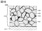
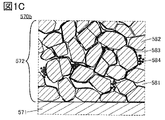
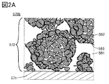
- FIG. 1B, 1C, 2A and 2B are enlarged views of a square region 570b surrounded by a broken line in FIG. 1A.
- the active material layer 572 has an electrolyte 581, particles 582, and graphene 583.
- the active material layer 572 shown in FIG. 1B has particles 582 covered with graphene 583. Further, in FIG. 1B, graphene 583 may cover the surface of a plurality of particles 582.
- graphene 583 may also cover the surface of the plurality of particles 582. Further, graphene 583 is distributed in the electrode so as to form a three-dimensional conductive path.
- a plurality of particles 582 are aggregated. Of the plurality of agglomerated particles 582, some particles are covered with graphene 583. Further, graphene 583 is distributed in the electrode so as to form a three-dimensional conductive path.
- the plurality of graphene 583s form a three-dimensional network structure, and particles 582 are arranged between the plurality of graphene 583s.
- Particle 582 preferably functions as an active material.
- a material that functions as an active material can be used.
- the particles 582 preferably have, for example, a material that functions as an active material. In the present specification and the like, the particles 582 are referred to as active material particles.
- active material particles Various materials can be used as the particles 582. The materials that can be used as the particles 582 will be described later.
- the active material layer 572 has graphene 583.
- Graphene 583 can function as a conductive agent.
- the active material layer 572 has a carbon-based material such as carbon black, graphite, carbon fiber, fullerene, etc. in addition to graphene.
- a carbon-based material such as carbon black, graphite, carbon fiber, fullerene, etc.
- acetylene black (AB) or the like can be used as the carbon black.
- graphite for example, natural graphite, artificial graphite such as mesocarbon microbeads, or the like can be used.
- These carbon-based materials have high conductivity and can function as a conductive agent in the active material layer.
- these carbon-based materials may function as an active material.
- 1B and 1C show an example in which the active material layer 572 has acetylene black 584.
- the carbon fiber for example, a mesophase pitch carbon fiber, an isotropic pitch carbon fiber, or the like can be used. Further, as the carbon fiber, carbon nanofiber, carbon nanotube, or the like can be used. The carbon nanotubes can be produced, for example, by a vapor phase growth method.
- the active material layer may have one or more selected from metal powders such as copper, nickel, aluminum, silver, and gold, metal fibers, and conductive ceramic materials as the conductive agent.
- the content of the conductive auxiliary agent with respect to the total amount of the active material layer is preferably 1 wt% or more and 10 wt% or less, and more preferably 1 wt% or more and 5 wt% or less.
- graphene oxide is used with respect to the total amount of the active material, graphene oxide and binder in the slurry for forming the active material layer.
- the content of is preferably 1 wt% or more and 10 wt% or less, and more preferably 1 wt% or more and 5 wt% or less.
- the graphene of one aspect of the present invention allows lithium to easily pass through, the charge / discharge rate of the secondary battery can be increased.
- Particle-like carbon-containing compounds such as carbon black and graphite, and fibrous carbon-containing compounds such as carbon nanotubes easily enter minute spaces.
- the minute space refers to, for example, a region between a plurality of active materials.
- a carbon-containing compound that easily enters a minute space and a sheet-shaped carbon-containing compound such as graphene that can impart conductivity over multiple particles, the density of the electrodes can be increased and an excellent conductive path can be obtained. Can be formed.
- the secondary battery has the electrolyte of one aspect of the present invention, the operational stability of the secondary battery can be enhanced. That is, the secondary battery of one aspect of the present invention can have both high energy density and stability, and is effective as an in-vehicle secondary battery.
- the energy required to move it increases, and the cruising range also decreases.
- the cruising range can be extended with almost no change in the total weight of the vehicle equipped with the secondary battery of the same weight.
- the ratio in the electrodes can be reduced. Therefore, since the surface area of the conductive agent can be reduced in the electrode, decomposition of the electrolytic solution can be suppressed. Decomposition of electrolytes can occur significantly, especially at high temperatures. Therefore, the secondary battery using the electrode of one aspect of the present invention can suppress deterioration at a high temperature. Further, since graphene has high conductivity, the secondary battery can be operated with a high output even at a low temperature. Therefore, by using the electrode of one aspect of the present invention, it is possible to obtain an in-vehicle secondary battery having a wide operating temperature range. Further, by using an ionic liquid as the electrolyte, decomposition of the electrolytic liquid at a high temperature can be suppressed, and a secondary battery operating at a high temperature can be obtained.
- the secondary battery of one aspect of the present invention can be miniaturized due to its high energy density, and can be quickly charged because of its high conductivity. Therefore, the configuration of the secondary battery according to one aspect of the present invention is also effective in a portable information terminal.
- the active material layer 572 preferably has a binder (not shown).
- the binder binds or fixes the electrolyte and the active material, for example. Further, the binder can bind or fix an electrolyte and a carbon-based material, an active material and a carbon-based material, a plurality of active materials to each other, a plurality of carbon-based materials, and the like.
- binders polystyrene, methyl polyacrylate, methyl polymethacrylate (polymethylmethacrylate, PMMA), sodium polyacrylate, polyvinyl alcohol (PVA), polyethylene oxide (PEO), polypropylene oxide, polyimide, polyvinyl chloride, polytetra It is preferable to use materials such as fluoroethylene, polyethylene, polypropylene, polyisobutylene, polyethylene terephthalate, nylon, polyvinylidene fluoride (PVDF), polyacrylonitrile (PAN), ethylenepropylene diene polymer, polyvinyl acetate, and nitrocellulose.
- PVDF polyvinylidene fluoride
- PAN polyacrylonitrile
- Polyimide has excellent stable properties thermally, mechanically and chemically.
- a dehydration reaction and a cyclization (imidization) reaction are carried out. These reactions can be carried out, for example, by heat treatment.
- graphene having a functional group containing oxygen is used as graphene and polyimide is used as a binder in the electrode of one aspect of the present invention
- graphene can be reduced by the heat treatment, and the process can be simplified.
- heat treatment can be performed at a heating temperature of, for example, 200 ° C. or higher. By performing the heat treatment at a heating temperature of 200 ° C. or higher, the reduction reaction of graphene can be sufficiently performed, and the conductivity of the electrode can be further enhanced.
- Fluoropolymer which is a polymer material having fluorine, specifically polyvinylidene fluoride (PVDF) or the like can be used.
- PVDF is a resin having a melting point in the range of 134 ° C. or higher and 169 ° C. or lower, and is a material having excellent thermal stability.
- a rubber material such as styrene-butadiene rubber (SBR), styrene-isoprene-styrene rubber, acrylonitrile-butadiene rubber, butadiene rubber, or ethylene-propylene-diene copolymer as the binder.
- SBR styrene-butadiene rubber
- fluororubber can be used as the binder.
- a water-soluble polymer for example, a polysaccharide or the like can be used.
- a polysaccharide one or more selected from cellulose derivatives such as carboxymethyl cellulose (CMC), methyl cellulose, ethyl cellulose, hydroxypropyl cellulose, diacetyl cellulose, and regenerated cellulose, and starch and the like can be used. Further, it is more preferable to use these water-soluble polymers in combination with the above-mentioned rubber material.
- the binder may be used in combination of a plurality of the above.
- graphene 583 is flexible and has flexibility, and can cling to particles 582 like natto. Further, for example, the particles 582 can be compared to soybean, and the graphene 583 can be compared to a sticky component, for example, polyglutamic acid.
- a sticky component for example, polyglutamic acid.
- a plurality of graphenes 583 form a three-dimensional network structure, a structure in which polygons are arranged, for example, a honeycomb structure in which hexagons are arranged in a matrix, and an electrolyte, a plurality of active materials, and a plurality of carbon-based materials are formed in the mesh.
- graphene can form a three-dimensional conductive path and suppress the dropping of the electrolyte from the current collector.
- polygons having different numbers of sides may be mixed and arranged. Therefore, graphene 583 may function as a conductive agent and a binder in the active material layer 572.
- the particles 582 can have various shapes such as a rounded shape and a shape having corners. Further, in the cross section of the electrode, the particles 582 can have various cross-sectional shapes such as a circle, an ellipse, a figure having a curve, a polygon, and the like. For example, FIG. 2A shows an example in which the cross-sectional shape of the particle 582 has a rounded shape, but the cross-sectional shape of the particle 582 may have an angle. Further, a part may be rounded and a part may have corners.
- Negative negative active materials include materials that can react with carrier ions of secondary batteries, materials that can insert and remove carrier ions, materials that can alloy with metals that become carrier ions, and carrier ions. It is preferable to use a material capable of dissolving and precipitating the metal.
- Silicon can be used as the negative electrode active material.
- the electrode 570 it is preferable to use particles having silicon as the particles 582.
- a metal or compound having one or more elements selected from tin, gallium, aluminum, germanium, lead, antimony, bismuth, silver, zinc, cadmium, and indium can be used as the negative electrode active material.
- alloy-based compounds using such elements include Mg 2 Si, Mg 2 Ge, Mg 2 Sn, SnS 2 , V2 Sn 3 , FeSn 2 , CoSn 2 , Ni 3 Sn 2 , and Cu 6 Sn 5 .
- a material having a low resistance may be used by adding phosphorus, arsenic, boron, aluminum, gallium or the like as impurity elements to silicon.
- a silicon material predoped with lithium may be used.
- a predoping method there are methods such as mixing and annealing lithium fluoride or lithium carbonate and silicon, and a mechanical alloy of lithium metal and silicon.
- lithium is doped by a charge / discharge reaction in combination with an electrode such as lithium metal, and then an electrode that becomes a counter electrode using the doped electrode (for example, a positive electrode with respect to a pre-doped negative electrode). May be combined to produce a secondary battery.
- silicon nanoparticles can be used as the particles 582.
- the average diameter of the silicon nanoparticles is, for example, preferably 5 nm or more and less than 1 ⁇ m, more preferably 10 nm or more and 300 nm or less, and further preferably 10 nm or more and 100 nm or less.
- Silicon nanoparticles may have crystallinity. Further, the silicon nanoparticles may have a crystalline region and an amorphous region.
- the material having silicon for example, a material represented by SiO z (z is preferably smaller than 2, more preferably 0.5 or more and 1.6 or less) can be used.
- a form having a plurality of crystal grains in one particle can be used.
- a form having one or a plurality of silicon crystal grains in one particle can be used.
- the one particle may have silicon oxide around the crystal grain of silicon.
- the silicon oxide may be amorphous. It may be a particle in which graphene is clinging to a secondary particle of silicon.
- Li 2 SiO 3 and Li 4 SiO 4 can be used as the compound having silicon.
- Li 2 SiO 3 and Li 4 SiO 4 may be crystalline or amorphous, respectively.
- the analysis of the compound having silicon can be performed using NMR, XRD, Raman spectroscopy, SEM, TEM, EDX and the like.
- the negative electrode active material for example, carbon-based materials such as graphite, graphitizable carbon, non-graphitizable carbon, carbon nanotubes, carbon black and graphene can be used.
- the negative electrode active material for example, an oxide having one or more elements selected from titanium, niobium, tungsten and molybdenum can be used.
- the negative electrode active material a plurality of metals, materials, compounds, etc. shown above can be used in combination.
- Examples of the negative electrode active material include SnO, SnO 2 , titanium dioxide (TIO 2 ), lithium titanium oxide (Li 4 Ti 5 O 12 ), lithium-graphite interlayer compound ( Liz C 6 ), and niobium pentoxide (Nb 2 O). 5 ) Oxides such as tungsten oxide (WO 2 ) and molybdenum oxide (MoO 2 ) can be used.
- Li 3 -z Mz N (M Co, Ni, Cu, z of 0 or more and less than 3) having a Li 3N type structure, which is a compound nitride of lithium and a transition metal, is used.
- Li 3N type structure which is a compound nitride of lithium and a transition metal.
- Li 2.6 Co 0.4 N 3 shows a large charge / discharge capacity (900 mAh / g) and is preferable.
- a double nitride of lithium and a transition metal as a negative electrode material because it can be combined with a material such as V2 O 5 and Cr 3 O 8 which does not contain lithium ions as a positive electrode material. Even when a material containing lithium ions is used as the positive electrode material, a double nitride of lithium and a transition metal can be used as the negative electrode material by desorbing the lithium ions contained in the positive electrode material in advance.
- a material that causes a conversion reaction can also be used as a negative electrode active material.
- a transition metal oxide that does not undergo an alloying reaction with lithium such as cobalt oxide (CoO), nickel oxide (NiO), and iron oxide (FeO)
- CoO cobalt oxide
- NiO nickel oxide
- FeO iron oxide
- Materials that cause a conversion reaction include oxides such as Fe 2 O 3 , CuO, Cu 2 O, RuO 2 , Cr 2 O 3 , sulfides such as CoS 0.89 , NiS, and CuS, and Zn 3 N 2 .
- Cu nitrides such as Cu 3 N, Ge 3 N 4 and the like
- phosphodies such as NiP 2 , FeP 2 and CoP 3
- fluorides such as FeF 3 and BiF 3 . Since the potential of the fluoride is high, it may be used as a positive electrode material.
- the particles 582 may change in volume due to charge / discharge, but by arranging an electrolyte having fluorine between a plurality of particles 582 in the electrode, the particles are slippery even if the volume changes during charge / discharge. Since the formation of cracks is suppressed, there is an effect that the cycle characteristics are dramatically improved. It is important that an organic compound having fluorine is present between the plurality of active substances constituting the electrode.
- the electrode 570 is a positive electrode
- particles having a positive electrode active material can be used as the particles 582.
- the positive electrode active material include an olivine-type crystal structure, a layered rock salt-type crystal structure, and a composite oxide having a spinel-type crystal structure. Examples thereof include compounds such as LiFePO 4 , LiFeO 2 , LiNiO 2 , LiMn 2 O 4 , V 2 O 5 , Cr 2 O 5 , and MnO 2 .
- lithium nickelate LiNiO 2 or LiNi 1 -z Mj z O 2 ( 0 ⁇ z ⁇ 1)
- Mj Co, Al, etc.
- a lithium manganese composite oxide that can be represented by the composition formula Li a Mn b Mk c Od can be used.
- the element Mk a metal element selected from other than lithium and manganese, silicon, and phosphorus are preferably used, and nickel is more preferable.
- the lithium-manganese composite oxide refers to an oxide containing at least lithium and manganese, and includes chromium, cobalt, aluminum, nickel, iron, magnesium, molybdenum, zinc, indium, gallium, copper, titanium, niobium, and silicon. And may contain at least one element selected from the group consisting of phosphorus and the like.
- the positive electrode active material particles having a plurality of the positive electrode active materials listed above may be used.
- one of the positive electrode active materials and the other one mentioned above may be used as particles having a structure in which at least a part of one of the positive electrode active materials is covered by the other.
- Such particles having a structure in which at least a part of one is covered by the other may be referred to as a positive electrode active material complex.
- the compounding treatment includes, for example, a compounding process using mechanical energy such as a mechanochemical method, a mechanofusion method, and a ball mill method, and a compounding process by a liquid phase reaction such as a co-precipitation method, a hydrothermal method, and a sol-gel method.
- the treatment and the composite treatment can be performed by a gas phase reaction such as a barrel sputtering method, an ALD (Atomic Layer Deposition) method, a vapor deposition method, and a CVD (Chemical Vapor Deposition) method. can. Further, it is preferable to perform a heat treatment after the compounding treatment.
- the compounding treatment may be referred to as a surface coating treatment or a coating treatment.
- the positive electrode active material particles may form secondary particles.
- the particles 582 may be replaced with secondary particles formed by the positive electrode active material particles.
- a material having a layered rock salt type crystal structure such as lithium cobalt oxide (LiCoO 2 ) has a high discharge capacity and is excellent as a positive electrode active material for a secondary battery.
- the material having a layered rock salt type crystal structure include a composite oxide represented by LiMO 2 .
- the element M is, for example, one or more elements including a transition metal.
- the element M is, for example, one or more metals containing cobalt.
- the element M can contain, for example, one or more elements selected from magnesium, calcium, zirconium, lanthanum, barium, copper, potassium, sodium, and zinc in addition to one or more metals including cobalt.
- the positive electrode active material has lithium, an element M, and an additive element X.
- the additive element X for example, magnesium, calcium, zirconium, lanthanum, barium, copper, potassium, sodium, zinc, titanium, ittrium, nickel, aluminum, cobalt, manganese, vanadium, iron, chromium, niobium, hafnium, silicon, sulfur, Examples include phosphorus, boron, arsenic, chlorine, and fluorine.
- Examples of the lithium composite oxide represented by LiMO 2 include lithium cobalt oxide, nickel-cobalt-lithium manganate, nickel-cobalt-lithium aluminum oxide, and nickel-cobalt-manganese-lithium aluminum oxide.
- cobalt When cobalt is used as the element M in an amount of 75 atomic% or more, preferably 90 atomic% or more, more preferably 95 atomic% or more, there are many advantages such as relatively easy synthesis, easy handling, and excellent cycle characteristics.
- the raw material when nickel is used as the element M in an amount of 33 atomic% or more, preferably 60 atomic% or more, more preferably 80 atomic% or more, the raw material may be cheaper than the case where the amount of cobalt is large, and the weight per weight is increased. It is preferable because the charge / discharge capacity may increase.
- the particle size may become smaller. Therefore, for example, the above-mentioned third particle preferably contains nickel as the element M in an amount of 33 atomic% or more, preferably 60 atomic% or more, and more preferably 80 atomic% or more.
- the element M has a part of nickel together with cobalt, the displacement of the layered structure composed of the octahedron of cobalt and oxygen may be suppressed. Therefore, the crystal structure may become more stable especially in a charged state at a high temperature, which is preferable.
- nickel easily diffuses into the inside of lithium cobalt oxide, and it is considered that nickel may be present at the cobalt site during discharge but may be cation-mixed and located at the lithium site during charging.
- Nickel present in lithium sites during charging functions as a pillar supporting the layered structure consisting of cobalt and oxygen octahedrons, and is thought to contribute to the stabilization of the crystal structure.
- the element M does not necessarily have to contain manganese. Also, it does not necessarily have to contain nickel. Further, it does not necessarily have to contain cobalt.
- the particles of one aspect of the invention have lithium, element M, and oxygen. Further, the particles of one aspect of the present invention include a lithium composite oxide represented by LiMO 2 . Further, the particles of one aspect of the present invention have one or more selected from magnesium, fluorine, aluminum and nickel on the surface layer portion. By having one or more of these elements in the surface layer portion of the particles of one aspect of the present invention, it is possible to reduce the structural change due to charging and discharging in the surface layer portion of the particles and suppress the formation of cracks. In addition, irreversible structural changes in the surface layer portion of the particles can be suppressed, and capacity reduction due to repeated charging and discharging can be suppressed.
- the concentration of these elements in the surface layer portion is preferably higher than the concentration of these elements in the entire particle.
- the particles of one aspect of the present invention may have a structure in which a part of atoms is substituted with one or more selected from magnesium, fluorine, aluminum and nickel in the surface layer portion, for example, in the lithium composite oxide. ..
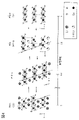
- the positive electrode active material will be described with reference to FIGS. 3 and 4.
- cations and anions alternate with the layered rock salt type crystal structure belonging to the space group R-3m, which is possessed by the composite oxide containing lithium and transition metals such as cobalt. It has a rock salt-type ion arrangement arranged in, and since transition metals and lithium are regularly arranged to form a two-dimensional plane, it refers to a crystal structure capable of two-dimensional diffusion of lithium. There may be defects such as cation or anion defects. Strictly speaking, the layered rock salt crystal structure may have a distorted lattice of rock salt crystals.
- the rock salt type crystal structure means a structure having a cubic crystal structure including a space group Fm-3m in which cations and anions are alternately arranged. There may be a cation or anion deficiency.
- TEM Transmission Electron Microscope, transmission electron microscope
- STEM Scanning Transmission Electron Microscope, scanning transmission electron microscope
- HAADF-STEM High Electron Microscope
- the contrast derived from the crystal plane can be obtained.
- the contrast from the (0003) plane is a bright band (bright strip) and a dark band (dark strip). ) Is repeated. Therefore, in the TEM image, when the angles between the bright lines are 0 degrees or more and 5 degrees or less, or 0 degrees or more and 2.5 degrees or less, the crystal planes are substantially the same, that is, the crystal orientations are substantially the same. Can be judged. Similarly, when the angle between the dark lines is 5 degrees or less, or 2.5 degrees or less, it can be determined that the orientation of the crystals is rough.
- the positive electrode active material produced according to one aspect of the present invention can reduce the displacement of the CoO 2 layer in repeated charging and discharging of a high voltage. Furthermore, the change in volume can be reduced. Therefore, the compound can realize excellent cycle characteristics. In addition, the compound can have a stable crystal structure in a high voltage state of charge. Therefore, the compound may not easily cause a short circuit when it is maintained in a high voltage charge state. In such a case, safety is further improved, which is preferable.
- the difference in crystal structure and the difference in volume per the same number of transition metal atoms between a fully discharged state and a state charged at a high voltage are small.
- FIG. 3 shows an example of the crystal structure before and after charging and discharging the positive electrode active material.
- the positive electrode active material shown in FIG. 3 preferably has a layered rock salt type crystal structure attributable to the space R-3m in the discharged state.
- the surface layer portion of the positive electrode active material has titanium, magnesium and oxygen in addition to or in place of the region represented by the layered rock salt type structure, and has crystals represented by a structure different from the layered rock salt type structure. You may. For example, it may have titanium, magnesium and oxygen, and may have crystals represented by a spinel structure.
- the theoretical capacity of the positive electrode active material means the amount of electricity when all the lithium that can be inserted and removed from the positive electrode active material is desorbed.
- the theoretical capacity of LiCoO 2 is 274 mAh / g
- the theoretical capacity of LiNiO 2 is 274 mAh / g
- the theoretical capacity of LiMn 2 O 4 is 148 mAh / g.
- the amount of lithium that can be inserted and removed in the positive electrode active material is indicated by x in the composition formula, for example, x in Li x CoO 2 or x in Li x MO 2 .
- Li x CoO 2 in the present specification can be appropriately read as Li x MO 2 .
- x (theoretical capacity-charging capacity) / theoretical capacity can be set.
- x in Li x CoO 2 is small means, for example, 0.1 ⁇ x ⁇ 0.24.
- the term "discharge completed" as used herein means a state in which the voltage is 2.5 V (counterpolar lithium) or less at a current of 100 mA / g, for example.
- the discharge voltage drops sharply by the time the discharge voltage reaches 2.5 V, so it is assumed that the discharge is completed under the above conditions.
- the charge capacity and / or the discharge capacity used for calculating x in Li x CoO 2 is preferably measured under conditions where there is no influence of short circuit and / or decomposition of the electrolyte. For example, data from a secondary battery with a sudden change in capacity, which appears to be a short circuit, should not be used to calculate x.
- the crystal structure of FIG. 3 at a charging depth of 0 (state in which discharging is completed) is R-3m (O3), which is the same as that of FIG.
- the positive electrode active material shown in FIG. 3 is an H1-3 type crystal when the charge depth is sufficiently charged, for example, when x is 0.24 or less, for example, about 0.2 or about 0.12 in the above. It has a crystal with a structure different from that of the structure.
- This structure is a space group R-3m, and the symmetry of the CoO2 layer is the same as that of the O3 type. Therefore, this structure is referred to as an O3'type crystal structure in the present specification and the like.
- the O3'type crystal structure is a space group R-3m, and ions such as cobalt and magnesium occupy the oxygen 6 coordination position.
- Light elements such as lithium may occupy the oxygen 4-coordination position.
- the O3'type crystal structure has Li at random between layers, but is similar to the CdCl 2 type crystal structure.
- This crystal structure similar to CdCl type 2 is similar to the crystal structure when lithium nickel oxide is charged to a charging depth of 0.94 (Li 0.06 NiO 2 ), but contains a large amount of pure lithium cobalt oxide or cobalt. It is known that layered rock salt type positive electrode active materials do not usually have this crystal structure.
- Layered rock salt crystals and anions of rock salt crystals have a cubic close-packed structure (face-centered cubic lattice structure). It is presumed that the O3'type crystal also has a cubic close-packed structure for anions. Therefore, when the layered rock salt type crystal and the rock salt type crystal come into contact with each other, there is a crystal plane in which the directions of the cubic close-packed structure composed of anions are aligned.
- the space group of layered rock salt type crystals and O3'type crystals is R-3m, which is different from the space group Fm-3m of rock salt type crystals (space group of general rock salt type crystals).
- the mirror index of the crystal plane satisfying the condition is different between the layered rock salt type crystal and the O3'type crystal and the rock salt type crystal.
- the orientations of the crystals are substantially the same when the orientations of the cubic close-packed structures composed of anions are aligned. be.
- the change in the crystal structure when charged at a high voltage and a large amount of lithium is desorbed is further suppressed as compared with the positive electrode active material shown in FIG.
- the dotted line in FIG. 3 there is almost no deviation of the CoO2 layer in these crystal structures.
- the positive electrode active material shown in FIG. 3 has high structural stability even when the charging voltage is high.
- the positive electrode active material shown in FIG. 3 is a crystal of R-3m (O3). Can retain structure.
- the positive electrode active material shown in FIG. 3 has a region capable of forming an O3'type crystal structure.
- the positive electrode active material in FIG. 3 may have an O3'type crystal structure. be.
- the voltage of the secondary battery is lower than the voltage based on the potential of the lithium metal described above by the potential of the graphite.
- the potential of graphite is about 0.05V to 0.2V with respect to the potential of lithium metal. Therefore, for example, even when the voltage of the secondary battery using graphite as the negative electrode active material is 4.3 V or more and 4.5 V or less, the positive electrode active material shown in FIG.
- the positive electrode active material shown in FIG. 3 may have an O3'type crystal structure.
- the crystal structure does not easily collapse even if charging and discharging are repeated at a high voltage.
- x 1 lithium cobalt oxide in Li x CoO 2 .
- the CoO 2 layer is a structure in which an octahedral structure in which oxygen is coordinated to cobalt is continuous with a plane in a shared ridge state. This may be referred to as a layer consisting of an octahedron of cobalt and oxygen.
- one CoO layer is present in the unit cell. Therefore, it may be called O1 type or monoclinic O1 type.
- the lithium cobalt oxide shown in FIG. 4 has a crystal structure of the space group R-3m.
- the coordinates of cobalt and oxygen in the unit cell are set to Co (0, 0, 0.42150 ⁇ 0.00016), O1 (0, It can be expressed as 0, 0.27671 ⁇ 0.00045) and O2 (0, 0, 0.11535 ⁇ 0.00045).
- O1 and O2 are oxygen atoms, respectively.
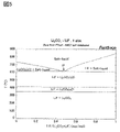
- Which unit cell should be used to represent the crystal structure of the positive electrode active material can be determined, for example, by Rietveld analysis of the XRD pattern. In this case, a unit cell having a small GOF (goodness of fit) value may be adopted.
- the change in the crystal structure between the discharged state where x is 1 and the state where x is 0.24 or less in Li x CoO 2 is further smaller than that in FIG. More specifically, the deviation between the two CoO layers in the state where x is 1 and the state where x is 0.24 or less can be reduced. In addition, it is possible to reduce the change in volume when compared per cobalt atom.
- the difference in volume per cobalt atom of the same number of R-3m (O3) in the discharged state and the O3'type crystal structure is 2.5% or less, and more specifically, 2. It is 2% or less, typically 1.8%.
- the coordinates of cobalt and oxygen in the unit cell are within the range of Co (0,0,0.5), O (0,0,x), 0.20 ⁇ x ⁇ 0.25. Can be indicated by.
- Magnesium which is randomly and dilutely present between the two CoO layers, that is, at the lithium site, has an effect of suppressing the displacement of the two CoO layers when charged at a high voltage. Therefore, if magnesium is present between the CoO 2 layers, it tends to have an O3'type crystal structure.
- a halogen compound such as a fluorine compound
- lithium cobalt oxide before the heat treatment for distributing magnesium throughout the particles.
- a halogen compound causes a melting point depression of lithium cobalt oxide. By lowering the melting point, it becomes easy to distribute magnesium throughout the particles at a temperature at which cationic mixing is unlikely to occur. Further, if a fluorine compound is present, it can be expected that the corrosion resistance to hydrofluoric acid generated by the decomposition of the electrolyte is improved.
- the magnesium concentration is higher than the desired value, the effect on stabilizing the crystal structure may be reduced. It is thought that magnesium enters cobalt sites in addition to lithium sites.
- the number of atoms of magnesium contained in the positive electrode active material produced by one aspect of the present invention is preferably 0.001 times or more and 0.1 times or less, and more than 0.01 times and less than 0.04 times the number of atoms of cobalt. More preferably, about 0.02 times is further preferable.
- the magnesium concentration shown here may be, for example, a value obtained by elemental analysis of the entire particles of the positive electrode active material using ICP-MS or the like, or a value of the blending of raw materials in the process of producing the positive electrode active material. May be based.
- the number of nickel atoms contained in the positive electrode active material is preferably 7.5% or less, preferably 0.05% or more and 4% or less, and more preferably 0.1% or more and 2% or less of the number of cobalt atoms.
- the nickel concentration shown here may be, for example, a value obtained by elemental analysis of the entire particles of the positive electrode active material using ICP-MS or the like, or a value of the blending of raw materials in the process of producing the positive electrode active material. It may be based.
- the average particle diameter is preferably 1 ⁇ m or more and 100 ⁇ m or less, more preferably 2 ⁇ m or more and 40 ⁇ m or less, and further preferably 5 ⁇ m or more and 30 ⁇ m or less.
- a positive electrode active material exhibits an O3'type crystal structure when charged at a high voltage is determined by XRD, electron beam diffraction, neutron beam diffraction, electron spin resonance (ESR), and electron spin resonance (ESR). It can be determined by analysis using nuclear magnetic resonance (NMR) or the like.
- XRD can analyze the symmetry of transition metals such as cobalt possessed by the positive electrode active material with high resolution, compare the height of crystallinity and the orientation of crystals, and analyze the periodic strain and crystallite size of the lattice. It is preferable in that sufficient accuracy can be obtained even if the positive electrode obtained by disassembling the secondary battery is measured as it is.
- the positive electrode active material is characterized in that the crystal structure does not change much between the state of being charged with a high voltage and the state of being discharged.
- a material in which a crystal structure having a large change from the discharged state occupies 50 wt% or more in a state of being charged at a high voltage is not preferable because it cannot withstand the charging / discharging of a high voltage.
- the desired crystal structure may not be obtained simply by adding an impurity element. For example, even if lithium cobalt oxide having magnesium and fluorine is common, the O3'type crystal structure becomes 60 wt% or more when charged at a high voltage, and the H1-3 type crystal structure becomes 50 wt% or more. There are cases where it occupies.
- the O3'type crystal structure becomes approximately 100 wt%, and when the predetermined voltage is further increased, an H1-3 type crystal structure may occur. Therefore, it is preferable that the crystal structure of the positive electrode active material is analyzed by XRD or the like. By using it in combination with measurement such as XRD, more detailed analysis can be performed.
- the positive electrode active material charged or discharged at a high voltage may change its crystal structure when exposed to the air.
- the O3'type crystal structure may change to the H1-3 type crystal structure. Therefore, it is preferable to handle all the samples in an inert atmosphere such as an atmosphere containing argon.
- the positive electrode active material shown in FIG. 4 is lithium cobalt oxide (LiCoO 2 ) to which the additive element X is not added.
- the crystal structure of lithium cobalt oxide shown in FIG. 4 changes depending on the charging depth.
- the lithium cobalt oxide having a charge depth of 0 (discharged state) has a region having a crystal structure of the space group R-3 m, and three CoO layers are present in the unit cell. Therefore, this crystal structure may be referred to as an O3 type crystal structure.
- the CoO 2 layer is a structure in which an octahedral structure in which oxygen is coordinated to cobalt is continuous with a plane in a shared ridge state.
- the space group P-3m1 has a crystal structure, and one CoO layer is present in the unit cell. Therefore, this crystal structure may be referred to as an O1 type crystal structure.
- lithium cobalt oxide when the charging depth is about 0.8 has a crystal structure of the space group R-3m.
- This structure can be said to be a structure in which CoO 2 structures such as P-3m1 (O1) and LiCoO 2 structures such as R-3m (O3) are alternately laminated. Therefore, this crystal structure may be referred to as an H1-3 type crystal structure.
- the H1-3 type crystal structure has twice the number of cobalt atoms per unit cell as the other structures.
- the c-axis of the H1-3 type crystal structure is shown by halving the unit cell.
- the coordinates of cobalt and oxygen in the unit cell are set to Co (0, 0, 0.42150 ⁇ 0.00016), O 1 (0, 0, 0.267671 ⁇ 0.00045). , O 2 (0, 0, 0.11535 ⁇ 0.00045).
- O 1 and O 2 are oxygen atoms, respectively.
- the H1-3 type crystal structure is represented by a unit cell using one cobalt and two oxygens.
- the O3'type crystal structure of one aspect of the present invention is preferably represented by a unit cell using one cobalt and one oxygen.
- the O3'type crystal structure has an O3 structure compared to the H1-3 type structure. Indicates that the change from is small. It is more preferable to use which unit cell to express the crystal structure of the positive electrode active material, for example, in the Rietveld analysis of the XRD pattern, the GOF (good of fitness) value is selected to be smaller. do it.
- the difference in volume is also large.
- the difference in volume between the H1-3 type crystal structure and the discharged state O3 type crystal structure is 3.0% or more.
- the continuous structure of two CoO layers such as P-3m1 (O1) of the H1-3 type crystal structure is likely to be unstable.
- Graphene 583 can be produced by mixing a material to be graphene as the material 801 and a compound having a halogen as the material 802 and performing a heat treatment.
- graphene oxide can be used as the material 801.
- a material that causes a eutectic reaction with the material 802 may be mixed as the material 803.
- the melting point due to the eutectic reaction is preferably lower than at least one of the melting point of the material 802 and the melting point of the material 803. Since the melting point is lowered by the eutectic reaction, the material 802 and the material 803 may easily react with the material 801 during the heat treatment. In addition, the surface of the material 801 may be easily covered with the material 802 and the material 803 during the heat treatment, and the covering property may be improved.
- a compound having oxygen and carbon can be used as the material 803, for example.
- carbonate can be used as the compound having oxygen and carbon.
- an organic compound can be used as the compound having oxygen and carbon.
- hydroxide may be used as the material 803.
- Carbonates, hydroxides, etc. are preferable because many of them are inexpensive and highly safe materials. Further, carbonates, hydroxides, etc. may generate a co-melting point with a compound having a halogen, which is preferable.
- the material 802 and the material 803 A more specific example of the material 802 and the material 803 will be described.
- the lithium fluoride when it is mixed with the material 801 and heated, the lithium fluoride may be difficult to melt and the reaction with the material 801 may be difficult to occur.
- the material 801 and the material 801 can be obtained by the eutectic reaction between the lithium fluoride and the material 803. Reaction is likely to occur.
- Lithium carbonate will be described as an example of the material 803 that causes a eutectic reaction with lithium fluoride.
- FIG. 5 is a phase diagram showing the relationship between the ratio of LiF and Li 2 CO 3 and the temperature.
- FIG. 5 is a quotation of data from FACT Salt Phase Diagrams.
- the melting point of LiF is about 850 ° C., but the melting point can be lowered by mixing Li 2 CO 3 . Therefore, for example, at the same heating temperature, it is easier to dissolve LiF and Li 2 CO 3 in a mixed manner than in the case of using only LiF, so that the reaction with the material 801 is more likely to occur.
- the temperature in heating can be lowered.
- the affinity of the material 801 with the surface can be enhanced.
- the CH bond of graphene may have a low affinity for fluorine, for example.
- the eutectic reaction of LiF and Li 2 CO 3 the affinity between the CH bond and the material having fluorine can be improved, and the reactivity can be enhanced.
- the temperature at point P is approximately 615 ° C.
- a value larger than 0.2 is preferable, and a value of 0.3 or more is more preferable.
- a value larger than 0.48 the fluorine content of graphene can be further increased.
- the fluorine content is too high, the coating property may deteriorate due to an increase in the melting point.
- a value smaller than 0.9 is preferable, and a value of 0.8 or less is more preferable.
- Material 801 is prepared in step S21.
- Material 801 is a raw material for graphene according to one aspect of the present invention.
- Material 801 is, for example, graphene before the addition of fluorine.
- Material 801 is, for example, graphene before reduction.
- Graphene oxide is used here as the material 801.
- a compound having a halogen is prepared as the material 802.
- a halogen compound having a metal A1 can be used as the metal A1 as the metal A1, for example, one or more selected from lithium, magnesium, aluminum, sodium, potassium, calcium, barium, lanthanum, cerium, chromium, manganese, iron, cobalt, nickel, zinc, zirconium, titanium, vanadium and niobium shall be used. Can be done.
- fluoride or chloride can be used as the halogen compound.
- the halogen contained in the compound having a halogen is represented as an element Z. Examples of Z include fluorine, chlorine, and the like.
- lithium fluoride is prepared as an example.
- a compound having oxygen and carbon is prepared as the material 803.
- a carbonate having the metal A2 can be used.
- the metal A2 for example, one or more selected from lithium, magnesium, aluminum, sodium, potassium, calcium, barium, lanthanum, cerium, chromium, manganese, iron, cobalt and nickel can be used.
- lithium carbonate is prepared as an example.
- step S31 the material 801 and the material 802 and the material 803 are mixed, the mixture is recovered in the step S32, and the mixture 804 is obtained in the step S33.
- step S51 the mixture 804 is heated.
- a reducing atmosphere it is preferable to perform heating in a reducing atmosphere because oxidation of the surface of the material 801 can be suppressed.
- the reducing atmosphere for example, it may be carried out in a nitrogen atmosphere or a noble gas atmosphere. Further, two or more kinds of gases of nitrogen and noble gas may be mixed and used. Further, heating may be performed under reduced pressure.
- the heating temperature is preferably higher than, for example, (M 2-550 ) [K] and lower than (M 2 +50) [K], and is preferably (M 2-400 ). ) [K] or more and M 2 [K] or less is more preferable.
- the compound tends to cause solid phase diffusion at a temperature higher than the Tanman temperature.
- the Tanman temperature is, for example, 0.757 times the melting point of an oxide. Therefore, for example, the heating temperature is preferably 0.757 times or more the co-melting point or higher than the temperature in the vicinity thereof.
- the heating temperature is preferably equal to or lower than the melting point of the material 802.
- the heating temperature is, for example, higher than (M 23 ⁇ 0.7) [K] and lower than (M 2 +50) [K]. It is preferable that it is (M 23 ⁇ 0.75) [K] or more and (M 2 +20) [K] or less, and it is higher than M 23 [K] and lower than (M 2 +10) [K]. It is more preferably (M 23 ⁇ 0.8) [K] or more and M 2 [K] or less, and more preferably M 23 [K] or more and M 2 [K] or less.
- the heating temperature is preferably, for example, larger than 350 ° C. and lower than 900 ° C., more preferably 390 ° C. or higher and 850 ° C. or lower, and 520 ° C. or higher and 910 ° C.
- the temperature is more preferably 570 ° C or higher and 860 ° C or lower, and further preferably 610 ° C or higher and 860 ° C or lower.
- the heating time is, for example, preferably 1 hour or more and 60 hours or less, and more preferably 3 hours or more and 20 hours or less.
- step S52 the heated mixture is recovered, and in step S53, graphene 583 is obtained.
- the graphene 583 produced in the example shown here is, for example, graphene added with fluorine.
- the graphene 583 produced in the example shown here is, for example, reduced graphene oxide and fluorine-added graphene.
- step S24 the particles 582 are used in step S24, and in step S31b, the particles 582 are further added to and mixed with the material 801 and the material 802 and the material 803, collected in step S32b, and recovered in step S33b.
- Mixture 804b may be obtained.
- graphene-covered particles can be produced.
- step S31b and step S32b step S31 and step S32 can be referred to, respectively.
- step S51b The mixture 804b is heated in step S51b, the heated mixture is recovered in step S52b, and the graphene-covered particles 582 (hereinafter, particles 582b) are obtained in step S53b.
- step S51b and step S52b step S51 and step S52 can be referred to, respectively.
- step S53b the particles 582 not covered with graphene and the graphene not covered with the particles 582 may be obtained together with the particles 582b.
- Particles 582b are, for example, graphene-coated particles 582 to which fluorine has been added. Further, the particles 582b are, for example, particles 582 covered with graphene and have fluorine.
- FIG. 7 is a flow chart showing an example of a method for manufacturing an electrode according to an aspect of the present invention.
- step S71 particles 582 are prepared.
- particles having silicon are prepared.
- the particles 582b described in the above-described production method may be used.
- a solvent is prepared.
- the solvent for example, one or a mixture of water, methanol, ethanol, acetone, tetrahydrofuran (THF), dimethylformamide (DMF), N-methylpyrrolidone (NMP) and dimethyl sulfoxide (DMSO) may be used. Can be done.
- step S73 the particles 582 prepared in step S71 and the solvent prepared in step S72 are mixed, the mixture is recovered in step S74, and the mixture E-1 is obtained in step S75.
- a kneader or the like can be used for mixing.
- the kneading machine for example, a rotation / revolution mixer or the like can be used.
- step S80 material 584b, which will later become graphene, is prepared.
- graphene oxide can be used as the material 584b.
- graphene 583 prepared by using the flow shown in FIG. 6 may be used.
- step S81 the mixture E-1 and the material 584b prepared in step S80 are mixed, and in step S82, the mixture is recovered to obtain the mixture E-2 (step S86).
- step S82 solid kneading (kneading at high viscosity) may be performed.
- a solvent may be added to reduce the viscosity, and further mixing may be carried out.
- step S87 prepare a binder.
- the materials described above can be used as the binder.
- polyimide is used.
- step S87 a precursor of a material used as a binder may be prepared.
- a polyimide precursor is prepared.
- step S88 the mixture E-2 and the binder prepared in step S87 or the precursor of the binder are mixed.
- step S89 the viscosity is adjusted. Specifically, for example, a solvent of the same type as the solvent prepared in step S72 is prepared and added to the mixture obtained in step S88. By adjusting the viscosity, for example, the thickness, density, etc. of the electrode obtained in the later step S97 may be adjusted.
- step S92 the mixture whose viscosity was adjusted in step S89 is mixed in step S90 and recovered in step S91 to obtain a mixture E-3 (step S92).
- the mixture E-3 obtained in step S92 is called, for example, a slurry.
- step S94 the mixture E-3 is applied onto the current collector prepared in step S93.
- a slot die method, a gravure method, a blade method, a method combining them, or the like can be used.
- a continuous coating machine or the like may be used for coating.
- step S95 the first heating is performed.
- the first heating causes the solvent to volatilize.
- the first heating may be performed in a temperature range of 50 ° C. or higher and 200 ° C. or lower, preferably 60 ° C. or higher and 150 ° C. or lower.
- heat treatment is performed on a hot plate in an air atmosphere under the conditions of 30 ° C. or higher and 70 ° C. or lower for 10 minutes or longer, and then, for example, under a reduced pressure environment under the conditions of room temperature or higher and 100 ° C. or lower for 1 hour or longer and 10 hours or lower.
- the heat treatment may be performed.
- the heat treatment may be performed using a drying oven or the like.
- heat treatment may be performed at a temperature of 30 ° C. or higher and 120 ° C. or lower for 30 seconds or longer and 2 hours or shorter.
- the temperature may be raised step by step.
- the heat treatment may be further performed at a temperature of 65 ° C. or higher for 1 minute or longer.
- step S96 the second heating is performed.
- the cycloaddition reaction of the polyimide occurs by the second heating.
- the second heating may cause a dehydration reaction of the polyimide.
- the first heating may cause a dehydration reaction of the polyimide.
- the cyclization reaction of the polyimide may occur in the first heating.
- the reduction reaction of the material 584b occurs in the second heating.
- step S97 an electrode having an active material layer provided on the current collector is obtained.
- the electrode obtained in step S97 is an electrode having graphene.
- the thickness of the active material layer thus formed may be, for example, preferably 5 ⁇ m or more and 300 ⁇ m or less, and more preferably 10 ⁇ m or more and 150 ⁇ m or less.
- the amount of the active material supported by the active material layer may be, for example, preferably 2 mg / cm 2 or more and 50 mg / cm 2 or less.
- the active material layer may be formed on both sides of the current collector, or may be formed on only one side. Alternatively, it may have a region in which active material layers are partially formed on both sides.
- pressing may be performed by a compression method such as a roll press method or a flat plate press method. Heat may be applied when pressing.
- a three-dimensional conductive path using a plurality of graphenes can be formed in the active material layer of the electrode. Further, a plurality of graphenes can be configured in the electrode in a mesh pattern.
- the graphene of one aspect of the present invention can be obtained in step S53 of FIG. 6A, step S53b of FIG. 6B, and step S97 of FIG. 7.
- the graphene obtained in each step may differ in the concentration of fluorine and the frequency of pores.
- the graphene obtained in each step may have a different oxygen concentration.
- At least a portion of the graphene of one aspect of the invention obtained in step S53b of FIG. 6B covers, for example, particles 582.
- the graphene of one aspect of the present invention obtained in step S97 of FIG. 7 is contained inside the electrode. Further, at least a part of the graphene of one aspect of the present invention obtained in step S97 of FIG. 7 covers, for example, particles 582. Further, the plurality of graphenes of one aspect of the present invention obtained in step S97 of FIG. 7 form a three-dimensional structure in the electrode.
- This embodiment can be used in combination with other embodiments as appropriate.
- the following is an example of a method for producing a material having a layered rock salt type crystal structure and represented by LiMO 2 .
- the metal M contains the metal Me1.
- the metal Me1 is one or more metals containing cobalt.
- the metal M can further contain the metal X in addition to the metal Me1.
- Metal X is one or more metals selected from magnesium, calcium, zirconium, lanthanum, barium, copper, potassium, sodium and zinc.
- Step S11 of FIG. 8A a lithium source and a transition metal source are prepared as materials for lithium and the transition metal.
- the transition metal source is shown as the Me1 source.
- transition metal source for example, at least one of manganese, cobalt, and nickel can be used.
- transition metal source when only cobalt is used, when only nickel is used, when two types of cobalt and manganese are used, when two types of cobalt and nickel are used, or when three types of cobalt, manganese, and nickel are used. May be used.
- the purity of the material is 3N (99.9%) or higher, preferably 4N (99.99%) or higher, more preferably 4N5 (99.995%) or higher, and even more preferably 5N (99%). .999%) or more.
- the capacity of the secondary battery can be increased and / or the reliability of the secondary battery can be increased.
- the transition metal source at this time has high crystallinity.
- the transition metal source has a single crystal grain.
- Examples of the evaluation of the crystallinity of the transition metal source include a TEM (transmission electron microscope) image, a STEM (scanning transmission electron microscope) image, a HAADF-STEM (high-angle scattering annular dark-field scanning transmission electron microscope) image, and an ABF-STEM (scanning transmission electron microscope). Circular bright-field scanning transmission electron microscope) It can be judged from the image and the like.
- X-ray diffraction X-ray diffraction
- electron diffraction electron diffraction
- neutron diffraction neutron diffraction and the like
- the above-mentioned crystallinity evaluation can be applied not only to the evaluation of the crystallinity of the transition metal source but also to the evaluation of the crystallinity of the primary particles or the secondary particles.
- Additive elements X include magnesium, calcium, zirconium, lantern, barium, titanium, ittrium, nickel, aluminum, cobalt, manganese, vanadium, iron, chromium, niobium, copper, potassium, sodium, zinc, chlorine, fluorine, hafnium, One or more selected from silicon, sulfur, phosphorus, boron and arsenic can be used. Further, as the additive element X, bromine and beryllium may be used in addition to the above elements. However, since bromine and beryllium are elements that are toxic to living organisms, it is preferable to use the above-mentioned additive element X.
- transition metal source oxides, hydroxides, etc. of the above metals exemplified as transition metals can be used.
- cobalt source for example, cobalt oxide, cobalt hydroxide and the like can be used.
- manganese source manganese oxide, manganese hydroxide or the like can be used.
- nickel source nickel oxide, nickel hydroxide or the like can be used.
- aluminum source aluminum oxide, aluminum hydroxide, or the like can be used.
- step S12 the above lithium source and transition metal source are crushed and mixed.
- Crushing and mixing can be performed dry or wet.
- the wording described as crushing may be read as crushing.
- a ball mill, a bead mill or the like can be used for mixing.
- zirconia balls it is preferable to use, for example, zirconia balls as a medium.
- the peripheral speed is preferably 100 mm / s or more and 2000 mm / s or less in order to suppress contamination from media or materials.
- the peripheral speed may be 838 mm / s (rotation speed 400 rpm, ball mill diameter 40 mm). Further, by using the above-mentioned dehydrated acetone in crushing and mixing, impurities that can be mixed in the material can be reduced.
- step S13 the materials mixed above are heated.
- the heating temperature of this step is preferably 800 ° C. or higher and lower than 1100 ° C., more preferably 900 ° C. or higher and 1000 ° C. or lower, and further preferably about 950 ° C. If the temperature is too low, the decomposition and melting of the lithium source and the transition metal source may be insufficient. On the other hand, if the temperature is too high, defects may occur due to the evaporation of lithium from the lithium source and / or the excessive reduction of the metal used as the transition metal source. For example, when cobalt is used as a transition metal, a defect may occur in which cobalt becomes divalent.
- the heating time can be, for example, 1 hour or more and 100 hours or less, and preferably 2 hours or more and 20 hours or less.
- the heating is preferably performed in an atmosphere such as dry air with little water (for example, a dew point of ⁇ 50 ° C. or lower, more preferably a dew point of ⁇ 80 ° C. or lower).
- heating may be performed in an atmosphere with a dew point of ⁇ 93 ° C.
- it is preferable that the heating is performed in an atmosphere where the impurity concentrations of CH 4 , CO, CO 2 and H 2 are 5 ppb (parts per billion) or less, respectively, because impurities that can be mixed in the material can be suppressed.
- the temperature rise is 200 ° C./h and the flow rate of the dry air is 10 L / min.
- the heated material can then be cooled to room temperature.
- the temperature lowering time from the specified temperature to room temperature is 10 hours or more and 50 hours or less.
- cooling to room temperature in step S13 is not essential.
- the crucible used for heating in step S13 is preferably made of a material that does not easily release impurities.
- a material that does not easily release impurities For example, an alumina crucible with a purity of 99.9% may be used.
- step S13 when recovering the material that has been heated in step S13, it is preferable to move the material from the crucible to the mortar and then recover the material because impurities are not mixed in the material. Further, it is preferable that the mortar is also made of a material that does not easily release impurities. Specifically, it is preferable to use an alumina mortar having a purity of 90% or more, preferably 99% or more. The same conditions as in step S13 can be applied to the heating steps described later other than step S13.
- the positive electrode active material 100 can be produced (step S14).
- the positive electrode active material 100 may be represented as a composite oxide (LiMO 2 ) having lithium, a transition metal, and oxygen.
- the impurity concentration is low, in other words, the purity is increased. You can get the material that has been made.
- the positive electrode active material obtained by such a method for producing a positive electrode active material is a material having high crystallinity.
- the positive electrode active material obtained by the method for producing a positive electrode active material according to one aspect of the present invention can increase the capacity of the secondary battery and / or enhance the reliability of the secondary battery.
- steps S11 to S14 are performed in the same manner as in FIG. 8A to prepare a composite oxide (LiMO 2 ) having lithium, a transition metal, and oxygen.
- a composite oxide synthesized in advance may be used as step S14.
- steps S11 to S13 can be omitted.
- a high-purity material it is preferable to use a high-purity material.
- the purity of the material is 99.5% or more, preferably 99.9% or more, and more preferably 99.99% or more.
- a step for heating may be provided between the step S14 and the next step S20.
- the heating can, for example, smooth the surface of the composite oxide.
- the heating may use the same conditions as the atmosphere and temperature of step S33, and the treatment time may be shorter than that of step S33.
- a smooth surface means that there are few irregularities, the whole is rounded, and the corners are rounded. Further, a state in which there is little foreign matter adhering to the surface is called smooth. Foreign matter is considered to be a cause of unevenness, and it is preferable that foreign matter does not adhere to the surface.
- an additive element X source is prepared.
- the material described above can be used.
- the additive element X a plurality of elements may be used.
- a solid phase method, a liquid phase method including a sol-gel method, a sputtering method, a vapor deposition method, a CVD (chemical vapor deposition) method, a PLD (pulse laser deposition) method, or the like is applied. be able to.
- a magnesium source (Mg source) and a fluorine source (F source) are prepared as the additive element X source. Further, a lithium source may be prepared in combination with the magnesium source and the fluorine source.
- magnesium source for example, magnesium fluoride, magnesium oxide, magnesium hydroxide, magnesium carbonate and the like can be used.
- fluorine source examples include lithium fluoride (LiF), magnesium fluoride (MgF 2 ), aluminum fluoride (AlF 3 ), titanium fluoride (TiF 4 ), cobalt fluoride (CoF 2 , CoF 3 ), and fluorine.
- the fluorine source is not limited to solid, for example, fluorine (F 2 ), carbon fluoride, sulfur fluoride, oxygen fluoride (OF 2 , O 2 F 2 , O 3 F 2 , O 4 F 2 , O 2 F). Etc. may be used to mix the mixture in the atmosphere in the heating step described later. Further, a plurality of fluorine sources may be mixed and used. Among them, lithium fluoride is preferable because it has a relatively low melting point of 848 ° C. and is easily melted in the heating step described later.
- lithium fluoride for example, lithium fluoride or lithium carbonate can be used. That is, lithium fluoride can be used both as a lithium source and as a fluorine source. Magnesium fluoride can be used both as a fluorine source and as a magnesium source.
- lithium fluoride LiF is prepared as a fluorine source
- magnesium fluoride MgF 2 is prepared as a fluorine source and a magnesium source.
- the amount of lithium fluoride increases, there is a concern that the amount of lithium becomes excessive and the cycle characteristics deteriorate.
- the term "neighborhood" means a value larger than 0.9 times and smaller than 1.1 times the value.
- a solvent it is preferable to use a protonic solvent such as a ketone such as acetone, an alcohol such as ethanol and isopropanol, ether, dioxane, acetonitrile, N-methyl-2-pyrrolidone (NMP) and the like, which is unlikely to react with lithium.
- a protonic solvent such as a ketone such as acetone, an alcohol such as ethanol and isopropanol, ether, dioxane, acetonitrile, N-methyl-2-pyrrolidone (NMP) and the like, which is unlikely to react with lithium.
- the above materials are mixed and crushed.
- Mixing can be done dry or wet, but wet is preferred because it can be crushed into smaller pieces.
- a ball mill, a bead mill, or the like can be used for mixing.
- a ball mill it is preferable to use, for example, zirconia balls as a medium.
- the conditions of the ball mill, the bead mill, and the like may be the same as those of step S12.
- this additive element X source is formed from a plurality of materials, it may be referred to as a mixture.
- the D50 (median diameter) of the above mixture is preferably 600 nm or more and 20 ⁇ m or less, and more preferably 1 ⁇ m or more and 10 ⁇ m or less.
- Such a finely divided mixture tends to uniformly adhere to the surface of the particles of the composite oxide when mixed with the composite oxide having lithium, a transition metal and oxygen in a later step. It is preferable that the mixture is uniformly adhered to the surface of the composite oxide particles because halogen and magnesium are easily distributed in the vicinity of the surface of the composite oxide particles after heating. If there is a region near the surface that does not contain halogen and magnesium, the above-mentioned O3'type crystal structure may not easily be formed in the charged state.
- the above is an example of a method of mixing two kinds of materials, but the present invention is not limited to this.
- four kinds of materials may be mixed to prepare an additive element X source. ..
- a single material i.e. one material, may be used to prepare the additive element X source.
- nickel source nickel oxide, nickel hydroxide or the like can be used.
- aluminum source aluminum oxide, aluminum hydroxide, or the like can be used.
- step S31 of FIG. 9 the LiMO 2 obtained in step S14 and the additive element X source are mixed.
- the mixing in step S31 is under milder conditions than the mixing in step S12 so as not to destroy the particles of the composite oxide.
- the rotation speed is lower or the time is shorter than the mixing in step S12.
- the dry type is a milder condition than the wet type.
- a ball mill, a bead mill or the like can be used for mixing.
- zirconia balls it is preferable to use, for example, zirconia balls as a medium.
- a ball mill using zirconia balls having a diameter of 1 mm is used for mixing at 150 rpm for 1 hour in a dry manner.
- the mixing is performed in a dry room having a dew point of ⁇ 100 ° C. or higher and ⁇ 10 ° C. or lower.
- Step S32> Next, in step S32 of FIG. 9, the materials mixed above are recovered to obtain a mixture 903.
- the present embodiment describes a method of adding a mixture of lithium fluoride and magnesium fluoride to lithium cobalt oxide having few impurities
- one aspect of the present invention is not limited to this.
- a starting material of lithium cobalt oxide to which a magnesium source, a fluorine source, or the like is added and heated may be used.
- lithium cobalt oxide to which magnesium and fluorine have been added in advance may be used. If lithium cobalt oxide to which magnesium and fluorine are added is used, the steps up to step S32 can be omitted, which is more convenient.
- a magnesium source and a fluorine source may be further added to lithium cobalt oxide to which magnesium and fluorine have been added in advance.
- step S33 the mixture 903 is heated in an oxygen-containing atmosphere.
- the heating is preferably performed so that the particles of the mixture 903 do not stick to each other.
- the additive is uniformly and evenly added over the entire surface of the particles.
- the particles of the mixture 903 adhere to each other during heating, the additive may be added unevenly to a part of the entire surface.
- the irregularities may increase, and defects such as cracks and / or cracks may increase. It is considered that this is due to the fact that the adhesion of the mixtures 903 to each other reduces the contact area with oxygen in the atmosphere and obstructs the path through which the additive diffuses.
- heating by a rotary kiln may be performed.
- the heating by the rotary kiln can be heated with stirring in either the continuous type or the batch type.
- the heating may be performed by a roller herring kiln.
- the heating temperature in step S33 needs to be higher than the temperature at which the reaction between LiMO 2 and the additive element X source proceeds.
- the temperature at which the reaction proceeds here may be any temperature at which mutual diffusion of the elements of LiMO 2 and the additive element X source occurs. Therefore, it may be possible to lower the melting temperature of these materials. For example, in the case of an oxide, solid phase diffusion occurs from 0.757 times (Tanman temperature T d ) or more of the melting temperature T m [K]. Therefore, the heating temperature in step S33 may be, for example, 500 ° C. or higher.
- the reaction is more likely to proceed, which is preferable.
- the co-melting point of LiF and MgF 2 is around 742 ° C, so that the heating temperature in step S33 is preferably 742 ° C or higher.
- the heating temperature is more preferably 830 ° C. or higher.
- the heating temperature needs to be less than the decomposition temperature of LiMO 2 (1130 ° C. in the case of LiCoO 2 ). Further, at a temperature near the decomposition temperature, there is a concern about decomposition of LiMO 2 , although the amount is small. Therefore, the heating temperature in step S33 is preferably less than 1130 ° C, more preferably 1000 ° C or lower, further preferably 950 ° C or lower, and even more preferably 900 ° C or lower.
- the heating temperature in step S33 is preferably 500 ° C. or higher and 1130 ° C. or lower, more preferably 500 ° C. or higher and 1000 ° C. or lower, further preferably 500 ° C. or higher and 950 ° C. or lower, and further preferably 500 ° C. or higher and 900 ° C. or lower.
- 742 ° C. or higher and 1130 ° C. or lower are preferable, 742 ° C. or higher and 1000 ° C. or lower are more preferable, 742 ° C. or higher and 950 ° C. or lower are further preferable, and 742 ° C. or higher and 900 ° C. or lower are further preferable.
- 830 ° C. or higher and 1130 ° C. or lower are preferable, 830 ° C. or higher and 1000 ° C. or lower are more preferable, 830 ° C. or higher and 950 ° C. or lower are further preferable, and 830 ° C. or higher and 900 ° C. or lower are further preferable.
- some materials for example, LiF, which is a fluorine source, may function as a flux.
- the heating temperature can be lowered to below the decomposition temperature of LiMO 2 , for example, 742 ° C or higher and 950 ° C or lower, and additives such as magnesium can be distributed near the surface to produce a positive electrode active material with good characteristics. ..
- LiF has a lighter specific gravity in a gaseous state than oxygen
- LiF in the mixture 903 decreases.
- the function as a flux is weakened. Therefore, it is necessary to heat while suppressing the volatilization of LiF.
- LiF is not used as a fluorine source or the like, Li and F on the surface of LiMO 2 may react to generate LiF and volatilize. Therefore, even if a fluoride having a melting point higher than that of LiF is used, it is necessary to suppress volatilization in the same manner.
- the mixture 903 in an atmosphere containing LiF, that is, to heat the mixture 903 in a state where the partial pressure of LiF in the heating furnace is high. By such heating, the volatilization of LiF in the mixture 903 can be suppressed.
- heating by a rotary kiln it is preferable to heat the mixture 903 by controlling the flow rate of the atmosphere containing oxygen in the kiln. For example, it is preferable to reduce the flow rate of the atmosphere containing oxygen, or to purge the atmosphere first and introduce the oxygen atmosphere into the kiln, and then the atmosphere does not flow.
- the mixture 903 can be heated in an atmosphere containing LiF, for example, by arranging a lid on a container containing the mixture 903.
- the heating is preferably performed at an appropriate time.
- the heating time varies depending on conditions such as the heating temperature, the size of the particles of LiMO 2 in step S14, and the composition. Smaller particles may be more preferred at lower temperatures or shorter times than larger particles.
- the heating temperature is preferably, for example, 600 ° C. or higher and 950 ° C. or lower.
- the heating time is, for example, preferably 3 hours or more, more preferably 10 hours or more, still more preferably 60 hours or more.
- the heating temperature is preferably, for example, 600 ° C. or higher and 950 ° C. or lower.
- the heating time is, for example, preferably 1 hour or more and 10 hours or less, and more preferably about 2 hours.
- the temperature lowering time after heating is preferably, for example, 10 hours or more and 50 hours or less.
- Step S34 Next, the heated material is recovered to prepare the positive electrode active material 100. At this time, it is preferable to further sift the recovered particles.
- the positive electrode active material 100 according to one aspect of the present invention can be produced (step S34).
- steps S11 to S14 are performed in the same manner as in FIG. 8A to prepare a composite oxide (LiMO 2 ) having lithium, a transition metal, and oxygen.
- a step for heating may be provided between steps S14 and S20.
- the heating may use the same conditions as the atmosphere and temperature of step S33, and the treatment time may be shorter than that of step S33.
- an additive element X1 source is prepared.
- the source of the additive element X1 it can be selected and used from the additive elements X described above.
- any one or a plurality selected from magnesium, fluorine, and calcium can be preferably used.
- a solid phase method, a liquid phase method including a sol-gel method, a sputtering method, a vapor deposition method, a CVD (chemical vapor deposition) method, a PLD (pulse laser deposition) method, or the like is applied. be able to.
- a magnesium source (Mg source) and a fluorine source (F source) are prepared as the first additive element X1.
- the magnesium source and the fluorine source can be appropriately pulverized, mixed, heated, and the like to obtain an additive element source (X1 source).
- steps S31 to S33 shown in FIG. 10 can be manufactured in the same process as steps S31 to S33 shown in FIG. 10
- Step S34a> the material heated in step S33 is recovered to prepare a composite oxide.
- an additive element X2 source is prepared.
- the source of the additive element X2 it can be selected and used from the additive elements X described above.
- any one or a plurality selected from nickel, titanium, boron, zirconium, and aluminum can be preferably used.
- nickel and aluminum are used as the additive element X2.
- a solid phase method, a liquid phase method including a sol-gel method, a sputtering method, a vapor deposition method, a CVD (chemical vapor deposition) method, a PLD (pulse laser deposition) method, or the like is applied. be able to.
- step S40 shown in FIG. 10 referring to step S20 shown in FIG. 9, pulverization, mixing, heating and the like can be appropriately performed to obtain an additive element source (X2 source).
- X2 source additive element source
- step S40 a plurality of second additive element sources (X2 sources) are independently prepared.
- a solvent used for the sol-gel method is prepared in addition to the additive element X2 source.
- a metal alkoxide can be used as the metal source of the sol-gel method, and for example, alcohol can be used as the solvent.
- aluminum is added aluminum isopropoxide can be used as a metal source, and isopropanol (2-propanol) can be used as a solvent.
- zirconium zirconium (IV) tetrapropoxide can be used as a metal source, and isopropanol can be used as a solvent.
- step S51 in FIG. 10 is a step of mixing the composite oxide produced in step S34a and the additive element X2 source produced in step S40.
- step S51 in FIG. 10 can be processed in the same process as step S31 shown in FIG.
- step S52 in FIG. 10 processing can be performed in the same process as step S32 shown in FIG.
- the material produced in step S52 of FIG. 10 is the mixture 904.
- the mixture 904 is a material containing the additive element X2 source added in step S40 in addition to the material of the mixture 903.
- step S53 in FIG. 10 processing can be performed in the same process as step S33 shown in FIG.
- Step S54 Next, the heated material is recovered to prepare the positive electrode active material 100. At this time, it is preferable to further sift the recovered particles.
- the positive electrode active material 100 according to one aspect of the present invention can be produced (step S54).
- the profile of each element in the depth direction may be changed.
- the concentration of the additive can be increased near the surface as compared to the inside of the particle.
- the ratio of the number of atoms of the additive element to the reference can be made higher in the vicinity of the surface than in the inside.
- a high-purity material is used as the transition metal source used in the synthesis, and a process with less impurities mixed in the synthesis is used to thoroughly eliminate the transition metal source and the impurities mixed in the synthesis.
- a region having a low impurity concentration and the additive element are introduced. It is possible to obtain a positive electrode active material in which the regions are controlled.
- a positive electrode active material having high crystallinity can be obtained.
- the positive electrode active material obtained by the method for producing a positive electrode active material according to one aspect of the present invention can increase the capacity of the secondary battery and / or enhance the reliability of the secondary battery.
- the additive element X may be added to the composite oxide as long as the layered rock salt type crystal structure can be obtained, and in FIG. 11, steps S11 to S34a are carried out in the same manner as in FIG. In the present production method 4, the step of adding the second additive element (X2) in two or more times will be described.
- step S40a shown in FIG. 11 one of the second additive element sources (hereinafter, X2a source is attached) is prepared.
- the X2a source the additive element X described in step S20 shown in FIG. 9 can be selected and used.
- the additive element X2a any one or a plurality selected from nickel, titanium, boron, zirconium, and aluminum can be preferably used.
- a solid phase method including a sol-gel method, a sputtering method, a vapor deposition method, a CVD (chemical vapor deposition) method, a PLD (pulse laser deposition) method, or the like. Can be done.
- FIG. 11 illustrates a case where nickel is used as the additive element X2a.
- step S40a shown in FIG. 11 referring to step S20 shown in FIG. 9, pulverization, mixing, heating and the like can be appropriately performed to obtain a second additive element source (X2a source).
- a nickel source is obtained as a second additive element source (X2a source) by using a solid phase method.
- Step S40b In addition to the second additive element source (hereinafter, X2b source is added) can be obtained by step S40b shown in FIG.
- a sol-gel method is used to obtain a second additive element source (X2b source).
- X2b source a sol-gel method
- a metal alkoxide can be used as the metal source of the sol-gel method, and for example, alcohol can be used as the solvent.
- aluminum isopropoxide can be used as the aluminum alkoxide
- zirconium isopropoxide can be used as the zirconium alkoxide
- isopropanol can be used as the solvent.
- the sol-gel reaction may be allowed to proceed here, or the sol-gel reaction may be allowed to proceed in the next step. If the sol-gel reaction is to proceed, it may be heated during mixing.
- X2b source a mixture containing an aluminum source and a zirconium source (also referred to as a mixed solution) is prepared.
- steps S51 to S53 shown in FIG. 11 can be manufactured under the same conditions as steps S31 to S33 shown in FIG. Through the above steps, in step S54, the positive electrode active material 100 according to one aspect of the present invention can be produced.
- the sol-gel reaction can proceed in step S53.
- This embodiment can be used in combination with other embodiments.
- the secondary battery has an exterior body (not shown), a positive electrode 503, a negative electrode 506, a separator 507, and an electrolyte in which a lithium salt and the like are dissolved.
- the separator 507 is provided between the positive electrode 503 and the negative electrode 506.
- the positive electrode 503 has a positive electrode active material. Further, the positive electrode 503 has a positive electrode active material layer 502 provided on the positive electrode current collector 501.
- the positive electrode active material layer 502 has, for example, a positive electrode active material, a conductive agent, and a binder. As the positive electrode of one aspect of the present invention, the electrode described in the previous embodiment can be used.
- the negative electrode 506 has a negative electrode active material. Further, the negative electrode 506 has a negative electrode active material layer 505 provided on the negative electrode current collector 504.
- the negative electrode active material layer 505 has, for example, a negative electrode active material, a conductive agent, and a binder. As the negative electrode of one aspect of the present invention, the electrode described in the previous embodiment can be used.
- the electrolyte preferably contains a solvent and a salt of a metal that becomes a carrier ion.
- an aprotonic organic solvent is preferable, and for example, ethylene carbonate (EC), propylene carbonate (PC), butylene carbonate, chloroethylene carbonate, vinylene carbonate, ⁇ -butyrolactone, ⁇ -valerolactone, dimethyl carbonate ( DMC), diethyl carbonate (DEC), ethylmethyl carbonate (EMC), methyl formate, methyl acetate, ethyl acetate, methyl propionate, ethyl propionate, propyl propionate, methyl butyrate, 1,3-dioxane, 1,4- Use one of dioxane, dimethoxyethane (DME), dimethyl sulfoxide, diethyl ether, methyl diglyme, acetonitrile, benzonitrile
- Ionic liquids consist of cations and anions, including organic cations and anions.
- Examples of the organic cation used for the electrolyte include aliphatic onium cations such as quaternary ammonium cations, tertiary sulfonium cations, and quaternary phosphonium cations, imidazolium cations, and aromatic cations such as pyridinium cations.
- anions used for the electrolyte monovalent amide anions, monovalent methide anions, fluorosulfonic acid anions, perfluoroalkyl sulfonic acid anions, tetrafluoroborate anions, perfluoroalkyl borate anions, hexafluorophosphate anions, etc.
- perfluoroalkyl phosphate anion and the like can be mentioned.
- Examples of the salt to be dissolved in the above solvent include LiPF 6 , LiClO 4 , LiAsF 6 , LiBF 4 , LiAlCl 4 , LiSCN, LiBr, LiI, Li 2 SO 4 , Li 2 B 10 Cl 10 , Li 2 B 12 .
- the electrolyte used in the secondary battery it is preferable to use a highly purified electrolyte solution containing less granular waste and elements other than the constituent elements of the electrolyte (hereinafter, also simply referred to as "impurities").
- impurities a highly purified electrolyte solution containing less granular waste and elements other than the constituent elements of the electrolyte
- the weight ratio of impurities to the electrolyte is preferably 1% or less, preferably 0.1% or less, and more preferably 0.01% or less.
- the electrolytes include vinylene carbonate (VC), propane sultone (PS), tert-butylbenzene (TBB), fluoroethylene carbonate (FEC), lithium bis (oxalate) borate (LiBOB), and dinitriles such as succinonitrile and adiponitrile.
- Additives such as compounds may be added.
- the concentration of the material to be added may be, for example, 0.1 wt% or more and 5 wt% or less with respect to the entire solvent.
- VC or LiBOB tends to form a good film and is particularly preferable.
- a solution containing a solvent and a salt as a carrier ion may be called an electrolytic solution.
- a polymer gel electrolyte obtained by swelling a polymer with an electrolytic solution may be used.
- the secondary battery can be made thinner and lighter.
- polymer for example, a polymer having a polyalkylene oxide structure such as polyethylene oxide (PEO), PVDF, polyacrylonitrile and the like can be used. Further, a copolymer or the like containing these can be used.
- PVDF-HFP which is a copolymer of PVDF and hexafluoropropylene (HFP)
- the polymer to be formed may have a porous shape.
- a solid electrolyte having an inorganic material such as a sulfide type and an oxide type, and a solid electrolyte having a polymer material such as PEO (polyethylene oxide) type can be used.
- PEO polyethylene oxide
- separator 507 for example, one made of paper, non-woven fabric, glass fiber, ceramics or the like can be used. Alternatively, those made of nylon (polyamide), vinylon (polyvinyl alcohol-based fiber), polyester, acrylic, polyolefin, polyurethane, polypropylene, polyethylene and the like can be used. It is preferable that the separator is processed into an envelope shape and arranged so as to wrap either the positive electrode or the negative electrode.
- the polymer film having polypropylene, polyethylene, etc. can be produced by a dry method or a wet method.
- the dry method is a manufacturing method in which a polymer film having polypropylene, polyethylene, polyimide or the like is stretched while being heated to form a gap between crystals and to make fine pores.
- the wet method is a manufacturing method in which a solvent is mixed with a resin in advance to form a film, and then the solvent is extracted to make holes.
- the left figure of FIG. 12B shows an enlarged view of the region 507a as an example of the separator 507 (when manufactured by the wet method).
- a structure in which a plurality of holes 587 are formed in the polymer film 588 is shown.
- the right figure of FIG. 12B shows an enlarged view of the region 507b as another example of the separator 507 (when manufactured by the dry method).
- a structure in which a plurality of holes 585 are formed in the polymer film 586 is shown.
- the diameter of the hole of the separator may differ between the surface layer portion of the surface facing the positive electrode after charging and discharging and the surface layer portion of the surface facing the negative electrode.
- the surface layer portion of the separator is preferably, for example, a region within 5 ⁇ m, more preferably within 3 ⁇ m from the surface.
- the separator may have a multi-layer structure.
- a structure in which two types of polymer materials are laminated may be used.
- polyamide-based material for example, nylon, aramid (meth-based aramid, para-based aramid) and the like can be used.
- This embodiment can be used in combination with other embodiments as appropriate.
- the secondary battery 500 shown in FIGS. 13A and 13B has a positive electrode 503, a negative electrode 506, a separator 507, an exterior body 509, a positive electrode lead electrode 510, and a negative electrode lead electrode 511.
- a cross-sectional view of the laminated type secondary battery shown in FIG. 13A or the like for example, as shown in FIG. 18 described later, a structure in which a positive electrode, a separator, and a negative electrode are laminated and surrounded by an exterior body can be used.
- FIG. 14A shows an example of the positive electrode 503 and the negative electrode 506.
- the positive electrode 503 has a positive electrode active material layer 502 on the positive electrode current collector 501. Further, it is preferable that the positive electrode 503 has a tab region where the positive electrode current collector 501 is exposed.
- the negative electrode 506 has a negative electrode active material layer 505 on the negative electrode current collector 504. Further, it is preferable that the negative electrode 506 has a tab region where the negative electrode current collector 504 is exposed.
- the negative electrode 506, the separator 507, and the positive electrode 503 are laminated.
- 14B shows the negative electrode 506, the separator 507, and the positive electrode 503 laminated.
- an example in which 5 sets of negative electrodes and 4 sets of positive electrodes are used is shown. It can also be called a laminate consisting of a negative electrode, a separator, and a positive electrode.
- the tab regions of the positive electrode 503 are joined to each other, and the positive electrode lead electrode 510 is joined to the tab region of the positive electrode on the outermost surface.
- the tab regions of the negative electrode 506 are bonded to each other, and the negative electrode lead electrode 511 is bonded to the tab region of the negative electrode on the outermost surface.
- the negative electrode 506, the separator 507, and the positive electrode 503 are arranged on the exterior body 509.
- the exterior body 509 is bent at the portion shown by the broken line. After that, the outer peripheral portion of the exterior body 509 is joined. For example, thermocompression bonding may be used for joining. At this time, a region (hereinafter referred to as an introduction port 516) that is not joined to a part (or one side) of the exterior body 509 is provided so that the electrolyte 508 can be put in later.
- an introduction port 516 a region that is not joined to a part (or one side) of the exterior body 509 is provided so that the electrolyte 508 can be put in later.
- the electrolyte 508 is introduced into the exterior body 509 from the introduction port 516 provided in the exterior body 509.
- the introduction of the electrolyte 508 is preferably carried out under a reduced pressure atmosphere or an inert atmosphere. And finally, the introduction port 516 is joined. In this way, the laminated type secondary battery 500 can be manufactured.
- the positive electrode lead electrode 510 and the negative electrode lead electrode 511 were led out from the same side to the outside of the exterior body, and the secondary battery 500 shown in FIG. 13A was manufactured.
- the secondary battery 500 shown in FIG. 13B can also be manufactured by leading the positive electrode lead electrode 510 and the negative electrode lead electrode 511 to the outside of the exterior body from the opposite sides.
- the secondary battery 600 shown in FIG. 16 has a positive electrode 503, a negative electrode 506, a separator 507, an exterior body 509, a positive electrode lead electrode 510, and a negative electrode lead electrode 511.
- the exterior body 509 is sealed in region 514.
- the laminated type secondary battery 600 can be manufactured by using, for example, the manufacturing apparatus shown in FIG.
- the manufacturing apparatus 670 shown in FIG. 17 has a member input chamber 671, a transfer chamber 672, a processing chamber 673, and a member take-out chamber 676.
- Each room can be configured to be connected to various exhaust mechanisms according to the intended use. Further, each room can be configured to be connected to various gas supply mechanisms according to the intended use.
- the inert gas is supplied into the manufacturing apparatus 670.
- As the gas supplied to the inside of the manufacturing apparatus 670 it is preferable to use a gas that has been highly purified by a gas purifier before being introduced into the manufacturing apparatus 670.
- the member charging room 671 is a room for charging a positive electrode, a separator, a negative electrode, an exterior body, and the like into the manufacturing apparatus 670.
- the transport chamber 672 has a transport mechanism 680.
- the treatment chamber 673 has a stage and an electrolyte dropping mechanism.
- the member take-out room 676 is a room for taking out the manufactured secondary battery to the outside of the manufacturing apparatus 670.
- the procedure for manufacturing the laminated secondary battery 600 is as follows.
- the exterior body 509b is placed on the stage 691 of the processing chamber 673, and then the positive electrode 503 is placed on the exterior body 509b (FIGS. 19A and 19B).
- the electrolyte 515a is dropped from the nozzle 694 onto the positive electrode 503 (FIGS. 19C and 19D).
- 19D is a cross section corresponding to the alternate long and short dash line AB in FIG. 19C.
- the description of the stage 691 may be omitted in order to avoid complicating the drawings.
- the dropping method for example, any one of a dispense method, a spray method, an inkjet method and the like can be used. Further, an ODF (One Drop Fill) method can be used for dropping the electrolyte.
- the electrolyte 515a By moving the nozzle 694, the electrolyte 515a can be dropped over the entire surface of the positive electrode 503. Alternatively, the electrolyte 515a may be dropped over the entire surface of the positive electrode 503 by moving the stage 691.
- the electrolyte is preferably dropped from a position where the shortest distance X from the surface to be dropped is greater than 0 mm and 1 mm or less.
- the viscosity of the electrolyte dropped from the nozzle or the like is in the range of 0.3 mPa ⁇ s or more and 1000 mPa ⁇ s or less at room temperature (25 ° C.), the electrolyte can be dropped from the nozzle.
- the temperature of the electrolyte is preferably equal to or higher than the melting point of the electrolyte, lower than the boiling point, or lower than the flash point.
- the separator 507 is placed on the positive electrode 503 so as to overlap the entire surface of the positive electrode 503 (FIG. 20A).
- the electrolyte 515b is dropped onto the separator 507 using the nozzle 694 (FIG. 20B).
- the negative electrode 506 is placed on the separator 507 (FIG. 20C).
- the negative electrodes 506 are arranged so as to overlap each other so as not to protrude from the separator 507 when viewed from above.
- the electrolyte 515c is dropped onto the negative electrode 506 using the nozzle 694 (FIG. 20D). After that, the laminated body 512 shown in FIG.
- the 18 can be manufactured by further laminating the laminated body of the positive electrode 503, the separator 507, and the negative electrode 506. Next, the positive electrode 503, the separator 507, and the negative electrode 506 are sealed by the exterior body 509a and the exterior body 509b (FIGS. 20E and 20F).
- the positive electrode and the negative electrode are arranged so that the positive electrode active material layer and the negative electrode active material layer sandwich the separator.
- the region where the negative electrode active material layer does not face the positive electrode active material layer is small or absent.
- the electrolyte has an ionic liquid and the negative electrode active material layer has a region not facing the positive electrode active material layer, the charge / discharge efficiency of the secondary battery may decrease. Therefore, in the secondary battery of one aspect of the present invention, for example, it is preferable that the end portion of the positive electrode active material layer and the end portion of the negative electrode active material layer are aligned as much as possible.
- the end portion of the positive electrode active material layer is located inside the end portion of the negative electrode active material layer.
- a plurality of secondary batteries are individually separated by sealing the exterior bodies 509a and 509b in the region 514 so as to surround the active material layer one by one and then dividing the laminated body 512 on the outside of the region 514. be able to.
- a frame-shaped resin layer 513 is formed on the exterior body 509b.
- a frame-shaped resin layer 513 is formed on the exterior body 509b.
- sealing is performed in the region 514 by thermocompression bonding or welding under atmospheric pressure. Further, it is also possible to perform only thermocompression bonding or sealing by welding without performing the above-mentioned sealing by light irradiation.
- FIG. 16 shows an example in which the exterior body 509 is sealed on four sides (sometimes called a four-sided seal), as shown in FIGS. 13A and 13B, it is sealed on three sides (called a three-sided seal). In some cases).
- a laminated secondary battery 600 can be manufactured.
- FIG. 21 shows an example of a cross-sectional view of the laminated body of one aspect of the present invention.
- the laminated body 550 shown in FIG. 21 is manufactured by arranging one separator between the positive electrode and the negative electrode while bending it.
- one separator 507 is folded back a plurality of times so as to be sandwiched between the positive electrode active material layer 502 and the negative electrode active material layer 505.
- the separator 507 is folded back at least 5 times.
- the separator 507 is not only provided so as to be sandwiched between the positive electrode active material layer 502 and the negative electrode active material layer 505, but also by further bending the extending portion, the plurality of positive electrode 503 and the negative electrode 506 are bundled together with tape or the like. You may try to do it.
- the electrolyte can be dropped onto the positive electrode 503.
- the electrolyte can be dropped onto the negative electrode 506.
- the electrolyte can be dropped onto the separator 507 before the separator is bent or after the separator 507 is bent and overlapped with the negative electrode 506 or the positive electrode 503. .. By dropping the electrolyte on at least one of the negative electrode 506, the separator 507, and the positive electrode 503, the negative electrode 506, the separator 507, or the positive electrode 503 can be impregnated with the electrolyte.
- the secondary battery 970 shown in FIG. 22A has a laminated body 972 inside the housing 971.
- the terminal 973b and the terminal 974b are electrically connected to the laminated body 972. At least a part of the terminal 973b and at least a part of the terminal 974b are exposed to the outside of the housing 971.
- the laminated body 972 As the laminated body 972, a structure in which a positive electrode, a negative electrode, and a separator are laminated can be applied. Further, as the laminated body 972, a positive electrode, a negative electrode, a structure in which a separator is wound, and the like can be applied.
- the laminated body 972 the laminated body having a structure in which the separator is folded back as shown in FIG. 21 can be used.
- a strip-shaped separator 976 is superposed on the positive electrode 975a, and the negative electrode 977a is superposed on the positive electrode 975a with the separator 976 in between. Then, the separator 976 is folded back and superposed on the negative electrode 977a.
- the positive electrode 975b is superposed on the negative electrode 977a with the separator 976 in between.
- the laminated body 972 can be manufactured by folding back the separator and arranging the positive electrode and the negative electrode in order.
- the structure including the laminated body produced in this way may be referred to as a "spin turn structure".
- the positive electrode lead electrode 973a is electrically connected to the positive electrode of the laminated body 972.
- a tab region can be provided on each of the positive electrodes of the laminated body 972, and each tab region and the positive electrode lead electrode 973a can be electrically connected by welding or the like.
- the negative electrode lead electrode 974a is electrically connected to the negative electrode of the laminated body 972.
- One laminated body 972 may be arranged inside the housing 971, or a plurality of laminated bodies 972 may be arranged.
- FIG. 23B shows an example of preparing two sets of laminated bodies 972.
- the prepared laminated body 972 is housed in the housing 971, the terminals 973b and the terminals 974b are mounted, and the housing 971 is sealed. It is preferable to electrically connect the conductor 973c to each of the positive electrode lead electrodes 973a of the plurality of laminated bodies 972. Further, it is preferable to electrically connect the conductor 974c to each of the negative electrode lead electrodes 974a of the plurality of laminated bodies 972.
- the terminal 973b is electrically connected to the conductor 973c, and the terminal 974b is electrically connected to the conductor 974c.
- the conductor 973c may have a conductive region and an insulating region. Further, the conductor 974c may have a region having conductivity and a region having insulation.
- a metal material for example, aluminum
- a metal material can be used as the housing 971.
- a resin material can be used as the housing 971.
- the safety valve is a valve that releases gas when the inside of the housing 971 reaches a predetermined pressure in order to prevent the battery from exploding.
- FIG. 24C An example of a cross-sectional view of a secondary battery according to another aspect of the present invention is shown in FIG. 24C.
- the secondary battery 560 shown in FIG. 24C is manufactured by using the laminated body 130 shown in FIG. 24A and the laminated body 131 shown in FIG. 24B.
- the laminated body 130, the laminated body 131, and the separator 507 are excerpted and shown in order to clarify the figure.
- the laminate 130 has a positive electrode 503 and a separator 507 having positive electrode active material layers on both sides of a positive electrode current collector, and a negative electrode 506 and a separator 507 having negative electrode active material layers on both sides of a negative electrode current collector.
- Positive electrode 503 having positive electrode active material layers on both sides of the positive electrode current collector are laminated in this order.
- the laminate 131 has a negative electrode 506 and a separator 507 having negative electrode active material layers on both sides of the negative electrode current collector, and a positive electrode 503 and a separator 507 having positive electrode active material layers on both sides of the positive electrode current collector.
- Negative electrodes 506 having negative electrode active material layers on both sides of the negative electrode current collector are laminated in this order.
- the method for manufacturing a secondary battery according to one aspect of the present invention can be applied when manufacturing a laminated body. Specifically, when laminating the negative electrode 506, the separator 507, and the positive electrode 503 in order to produce the laminated body, the electrolyte is dropped onto at least one of the negative electrode 506, the separator 507, and the positive electrode 503. By dropping a plurality of drops of the electrolyte, the negative electrode 506, the separator 507, or the positive electrode 503 can be impregnated with the electrolyte.
- the plurality of laminated bodies 130 and the plurality of laminated bodies 131 are covered with the wound separator 507.
- the electrolyte after arranging the laminated body 130, the electrolyte can be dropped onto the laminated body 130. Similarly, after arranging the laminated body 131, the electrolyte can be dropped onto the laminated body 131. Further, the electrolyte can be dropped onto the separator 507 before the separator 507 is bent or after the separator 507 is bent and overlapped with the laminated body. By dropping a plurality of drops of the electrolyte, the laminate 130, the laminate 131, or the separator 507 can be impregnated with the electrolyte.
- a secondary battery of another aspect of the present invention will be described with reference to FIGS. 25 and 26.
- the secondary battery shown here can be called a winding type secondary battery or the like.
- the housing 930 shown in FIG. 25A may be formed of a plurality of materials.
- the housing 930a and the housing 930b are bonded to each other, and the winding body 950 is provided in the region surrounded by the housing 930a and the housing 930b.
- an insulating material such as an organic resin can be used.
- a material such as an organic resin on the surface on which the antenna is formed it is possible to suppress the shielding of the electric field by the secondary battery 913. If the electric field shielding by the housing 930a is small, an antenna may be provided inside the housing 930a.
- a metal material can be used as the housing 930b.
- the wound body 950 has a negative electrode 931, a positive electrode 932, and a separator 933.
- the wound body 950 is a wound body in which the negative electrode 931 and the positive electrode 932 are overlapped and laminated with the separator 933 interposed therebetween, and the laminated sheet is wound.
- a plurality of layers of the negative electrode 931, the positive electrode 932, and the separator 933 may be further laminated.
- an electrolyte is dropped onto at least one of the negative electrode 931, the separator 933, and the positive electrode 932. .. That is, it is preferable to drop the electrolyte before turning the laminated sheet. By dropping a plurality of drops of the electrolyte, the negative electrode 931, the separator 933, or the positive electrode 932 can be impregnated with the electrolyte.
- a secondary battery 913 having a winding body 950a as shown in FIG. 26A may be used.
- the winding body 950a shown in FIG. 26A has a negative electrode 931, a positive electrode 932, and a separator 933.
- the negative electrode 931 has a negative electrode active material layer 931a.
- the positive electrode 932 has a positive electrode active material layer 932a.
- the separator 933 has a wider width than the negative electrode active material layer 931a and the positive electrode active material layer 932a, and is wound so as to overlap the negative electrode active material layer 931a and the positive electrode active material layer 932a. Further, it is preferable that the width of the negative electrode active material layer 931a is wider than that of the positive electrode active material layer 932a from the viewpoint of safety. Further, the wound body 950a having such a shape is preferable in terms of safety and productivity.
- the negative electrode 931 is electrically connected to the terminal 951.
- the terminal 951 is electrically connected to the terminal 911a.
- the positive electrode 932 is electrically connected to the terminal 952.
- the terminal 952 is electrically connected to the terminal 911b.
- the winding body 950a and the electrolyte are covered with the housing 930 to form the secondary battery 913.
- the housing 930 is provided with a safety valve, an overcurrent protection element, or the like. The safety valve is temporarily opened only when the inside of the housing 930 exceeds a predetermined internal pressure in order to prevent the battery from exploding.
- the secondary battery 913 may have a plurality of winding bodies 950a. By using a plurality of winding bodies 950a, it is possible to obtain a secondary battery 913 having a larger charge / discharge capacity.
- FIG. 27C shows a block diagram of a vehicle having a motor.
- the electric vehicle is equipped with a first battery 1301a and 1301b as a main drive secondary battery and a second battery 1311 that supplies electric power to the inverter 1312 that starts the motor 1304.
- the second battery 1311 is also referred to as a cranking battery or a starter battery.
- the second battery 1311 may have a high output and does not require much large capacity, and the capacity of the second battery 1311 is smaller than that of the first batteries 1301a and 1301b.
- a secondary battery manufactured by using the method for manufacturing a secondary battery according to one aspect of the present invention can be used for one or both of the first batteries 1301a and 1301b.
- first batteries 1301a and 1301b are connected in parallel, but three or more batteries may be connected in parallel. Further, if the first battery 1301a can store sufficient electric power, the first battery 1301b may not be present.
- the plurality of secondary batteries may be connected in parallel, may be connected in series, or may be connected in parallel and then further connected in series. Multiple secondary batteries are also called assembled batteries.
- a service plug or a circuit breaker capable of cutting off a high voltage without using a tool is provided, and the first battery 1301a has. It will be provided.
- the electric power of the first batteries 1301a and 1301b is mainly used to rotate the motor 1304, but the 42V system (high voltage system) in-vehicle parts (electric power steering 1307, heater 1308) via the DCDC circuit 1306. , Defogger 1309, etc.). Even if the rear wheel has a rear motor 1317, the first battery 1301a is used to rotate the rear motor 1317.
- the second battery 1311 supplies electric power to 14V system (low voltage system) in-vehicle parts (audio 1313, power window 1314, lamps 1315, etc.) via the DCDC circuit 1310.
- 14V system low voltage system
- in-vehicle parts audio 1313, power window 1314, lamps 1315, etc.
- first battery 1301a will be described with reference to FIG. 27A.
- FIG. 27A shows an example of a large battery pack 1415.
- One electrode of the battery pack 1415 is electrically connected to the control circuit unit 1320 by wiring 1421.
- the other electrode is electrically connected to the control circuit unit 1320 by wiring 1422.
- the battery pack may be configured by connecting a plurality of secondary batteries in series.
- control circuit unit 1320 may use a memory circuit including a transistor using an oxide semiconductor.
- a charge control circuit or a battery control system having a memory circuit including a transistor using an oxide semiconductor may be referred to as a BTOS (Battery operating system or Battery oxide semiconductor).
- the control circuit unit 1320 detects the terminal voltage of the secondary battery and manages the charge / discharge state of the secondary battery. For example, in order to prevent overcharging, both the output transistor of the charging circuit and the cutoff switch can be turned off almost at the same time.
- FIG. 27B An example of the block diagram of the battery pack 1415 shown in FIG. 27A is shown in FIG. 27B.
- the control circuit unit 1320 includes a switch unit 1324 including at least a switch for preventing overcharging, a switch for preventing overdischarge, a control circuit 1322 for controlling the switch unit 1324, and a voltage measuring unit for the first battery 1301a. And have.
- the control circuit unit 1320 sets the upper limit voltage and the lower limit voltage of the secondary battery to be used, and limits the upper limit of the current from the outside, the upper limit of the output current to the outside, and the like.
- the range of the lower limit voltage or more and the upper limit voltage or less of the secondary battery is within the voltage range recommended for use, and if it is out of the range, the switch unit 1324 operates and functions as a protection circuit.
- control circuit unit 1320 can also be called a protection circuit because it controls the switch unit 1324 to prevent over-discharging or over-charging. For example, when the control circuit 1322 detects a voltage that is likely to cause overcharging, the switch of the switch unit 1324 is turned off to cut off the current. Further, a PTC element may be provided in the charge / discharge path to provide a function of cutting off the current in response to an increase in temperature. Further, the control circuit unit 1320 has an external terminal 1325 (+ IN) and an external terminal 1326 ( ⁇ IN).
- the switch unit 1324 can be configured by combining one or both of an n-channel type transistor and a p-channel type transistor.
- the switch unit 1324 is not limited to a switch having a Si transistor using single crystal silicon, and is, for example, Ge (germanium), SiGe (silicon germanium), GaAs (gallium arsenic), GaAlAs (gallium aluminum arsenic), InP (phosphorization).
- the switch portion 1324 may be formed by a power transistor having (indium), SiC (silicon carbide), ZnSe (zinc selenium), GaN (gallium nitride), GaO z (gallium oxide; z is a real number larger than 0) and the like. ..
- the storage element using the OS transistor can be freely arranged by stacking it on a circuit using a Si transistor or the like, integration can be easily performed.
- the OS transistor can be manufactured by using the same manufacturing apparatus as the Si transistor, it can be manufactured at low cost. That is, it is also possible to stack the control circuit unit 1320 using the OS transistor on the switch unit 1324 and integrate them into one chip. Since the occupied volume of the control circuit unit 1320 can be reduced, the size can be reduced.
- the first batteries 1301a and 1301b mainly supply electric power to 42V system (high voltage system) in-vehicle devices, and the second battery 1311 supplies electric power to 14V system (low voltage system) in-vehicle devices.
- a lead-acid battery is often used as the second battery 1311 because of its cost advantage.
- the second battery 1311 may use a lead storage battery, an all-solid-state battery, or an electric double layer capacitor.
- the battery controller 1302 can set the charging voltage, charging current, and the like of the first batteries 1301a and 1301b.
- the battery controller 1302 can set charging conditions according to the charging characteristics of the secondary battery to be used and quickly charge the battery.
- the outlet of the charger or the connection cable of the charger is electrically connected to the battery controller 1302.
- the electric power supplied from the external charger charges the first batteries 1301a and 1301b via the battery controller 1302.
- a control circuit may be provided and the function of the battery controller 1302 may not be used, but the first batteries 1301a and 1301b are charged via the control circuit unit 1320 in order to prevent overcharging. Is preferable.
- the connection cable or the connection cable of the charger is provided with a control circuit.
- the control circuit unit 1320 may be referred to as an ECU (Electronic Control Unit).
- the ECU is connected to a CAN (Controller Area Network) provided in the electric vehicle.
- CAN is one of the serial communication standards used as an in-vehicle LAN.
- the ECU also includes a microcomputer. Further, the ECU uses a CPU or a GPU.
- a next-generation clean energy vehicle such as a hybrid vehicle (HV), an electric vehicle (EV), or a plug-in hybrid vehicle (PHV)
- HV hybrid vehicle
- EV electric vehicle
- PHS plug-in hybrid vehicle
- agricultural machinery such as electric tractors, motorized bicycles including electrically assisted bicycles, motorcycles, electric wheelchairs, electric carts, small or large vessels, submarines, aircraft such as fixed-wing or rotary-wing aircraft, rockets, artificial satellites, etc.
- Secondary batteries can also be mounted on transport vehicles such as space explorers, planetary explorers, and spacecraft.
- the automobile 2001 shown in FIG. 28A is an electric vehicle that uses an electric motor as a power source for traveling. Alternatively, it is a hybrid vehicle in which an electric motor and an engine can be appropriately selected and used as a power source for traveling.
- the vehicle 2001 shown in FIG. 28A has the battery pack 1415 shown in FIG. 27A.
- the battery pack 1415 has a secondary battery module.
- the battery pack 1415 further preferably has a charge control device that is electrically connected to the secondary battery module.
- the secondary battery module has one or more secondary batteries.
- the automobile 2001 can be charged by receiving electric power from an external charging facility by a plug-in method, a non-contact power supply method, or the like to the secondary battery of the automobile 2001.
- the charging method or the standard of the connector may be appropriately performed by a predetermined method such as CHAdeMO (registered trademark) or a combo.
- the charging device may be a charging station provided in a commercial facility or a household power source.
- the plug-in technology can charge a secondary battery mounted on an automobile 2001 by supplying electric power from the outside. Charging can be performed by converting AC power into DC power via a conversion device such as an ACDC converter.
- a power receiving device on the vehicle and supply power from a ground power transmission device in a non-contact manner to charge the vehicle.
- this non-contact power supply system by incorporating a power transmission device on the road or the outer wall, charging can be performed not only while the vehicle is stopped but also while the vehicle is running. Further, electric power may be transmitted and received between two vehicles by using this contactless power feeding method. Further, a solar cell may be provided on the exterior portion of the vehicle to charge the secondary battery when the vehicle is stopped or running. An electromagnetic induction method or a magnetic field resonance method can be used for such non-contact power supply.
- FIG. 28B shows a large transport vehicle 2002 having a motor controlled by electricity as an example of a transport vehicle.
- the secondary battery module of the transport vehicle 2002 has, for example, a secondary battery of 3.5 V or more and 4.7 V or less as a four-cell unit, and has a maximum voltage of 170 V in which 48 cells are connected in series. Since it has the same functions as those in FIG. 28A except that the number of secondary batteries constituting the secondary battery module of the battery pack 2201 is different, the description thereof will be omitted.
- FIG. 28C shows, as an example, a large transport vehicle 2003 having a motor controlled by electricity.
- the secondary battery module of the transport vehicle 2003 has, for example, a maximum voltage of 600 V in which 100 or more secondary batteries of 3.5 V or more and 4.7 V or less are connected in series. Therefore, a secondary battery having a small variation in characteristics is required.
- a secondary battery having a small variation in characteristics is required.
- FIG. 28D shows, as an example, an aircraft 2004 having an engine that burns fuel. Since the aircraft 2004 shown in FIG. 28D has wheels for takeoff and landing, it can be said to be a part of a transportation vehicle, and a plurality of secondary batteries are connected to form a secondary battery module, which is charged with the secondary battery module. It has a battery pack 2203 including a control device.
- the secondary battery module of the aircraft 2004 has a maximum voltage of 32V in which eight 4V secondary batteries are connected in series, for example. Since it has the same functions as those in FIG. 28A except that the number of secondary batteries constituting the secondary battery module of the battery pack 2203 is different, the description thereof will be omitted.
- FIG. 29A is an example of an electric bicycle using the secondary battery of one aspect of the present invention.
- the secondary battery of one aspect of the present invention can be applied to the electric bicycle 2100 shown in FIG. 29A.
- the power storage device 2102 shown in FIG. 29B has, for example, a plurality of secondary batteries and a protection circuit.
- the electric bicycle 2100 includes a power storage device 2102.
- the power storage device 2102 can supply electricity to a motor that assists the driver. Further, the power storage device 2102 is portable, and FIG. 29B shows a state in which the power storage device 2102 is removed from the bicycle. Further, the power storage device 2102 contains a plurality of secondary batteries 2101 according to one aspect of the present invention, and the remaining battery level and the like can be displayed on the display unit 2103. Further, the power storage device 2102 has a control circuit 2104 capable of charging control or abnormality detection of a secondary battery, which is shown as an example in one aspect of the present invention. The control circuit 2104 is electrically connected to the positive electrode and the negative electrode of the secondary battery 2101.
- a small solid-state secondary battery may be provided in the control circuit 2104.
- the control circuit 2104 By providing the control circuit 2104 with a small solid-state secondary battery, it is possible to supply electric power to hold the data of the memory circuit of the control circuit 2104 for a long time.
- a synergistic effect on safety can be obtained.
- the secondary battery and the control circuit 2104 using the positive electrode active material 100 according to one aspect of the present invention as the positive electrode can greatly contribute to the eradication of accidents such as fires caused by the secondary battery.
- FIG. 29C is an example of a two-wheeled vehicle using a secondary battery of one aspect of the present invention.
- the scooter 2300 shown in FIG. 29C includes a power storage device 2302, a side mirror 2301, and a turn signal lamp 2303.
- the power storage device 2302 can supply electricity to the turn signal lamp 2303.
- the power storage device 2302 containing a plurality of secondary batteries using the positive electrode active material 100 according to one aspect of the present invention can have a high capacity and can contribute to miniaturization.
- a protection circuit for preventing overcharging and / or overdischarging of the secondary battery may be electrically connected to the secondary battery.
- the house shown in FIG. 30A has a power storage device 2612 having a secondary battery having stable battery characteristics and a solar panel 2610 by using the method for manufacturing a secondary battery according to one aspect of the present invention.
- the power storage device 2612 is electrically connected to the solar panel 2610 via wiring 2611 and the like. Further, the power storage device 2612 and the ground-mounted charging device 2604 may be electrically connected.
- the electric power obtained by the solar panel 2610 can be charged to the power storage device 2612. Further, the electric power stored in the power storage device 2612 can be charged to the secondary battery of the vehicle 2603 via the charging device 2604.
- the power storage device 2612 is preferably installed in the underfloor space. By installing it in the underfloor space, the space above the floor can be effectively used. Alternatively, the power storage device 2612 may be installed on the floor.
- the electric power stored in the power storage device 2612 can also be supplied to other electronic devices in the house. Therefore, even when the power cannot be supplied from the commercial power supply due to a power failure or the like, the electronic device can be used by using the power storage device 2612 as an uninterruptible power supply.
- FIG. 30B shows an application example of the power storage device according to one aspect of the present invention.
- a large power storage device 791 obtained by the method for manufacturing a secondary battery according to one aspect of the present invention is installed in the underfloor space portion 796 of the building 799.
- a control device 790 is installed in the power storage device 791, and the control device 790 is connected to a distribution board 703, a power storage controller 705 (also referred to as a control device), a display 706, and a router 709 by wiring. It is electrically connected.
- Electric power is sent from the commercial power supply 701 to the distribution board 703 via the drop line mounting portion 710. Further, electric power is transmitted to the distribution board 703 from the power storage device 791 and the commercial power supply 701, and the distribution board 703 transfers the transmitted electric power to a general load via an outlet (not shown). It supplies 707 and the power storage system load 708.
- the general load 707 is, for example, an electric device such as a television or a personal computer
- the storage system load 708 is, for example, an electric device such as a microwave oven, a refrigerator, or an air conditioner.
- the power storage controller 705 has a measurement unit 711, a prediction unit 712, and a planning unit 713.
- the measuring unit 711 has a function of measuring the amount of electric power consumed by the general load 707 and the power storage system load 708 during one day (for example, from 0:00 to 24:00). Further, the measuring unit 711 may have a function of measuring the electric power of the power storage device 791 and the electric power supplied from the commercial power source 701.
- the prediction unit 712 is based on the amount of electric power consumed by the general load 707 and the power storage system load 708 during the next day, and the demand consumed by the general load 707 and the power storage system load 708 during the next day. It has a function to predict the amount of electric power.
- the planning unit 713 has a function of making a charge / discharge plan of the power storage device 791 based on the power demand amount predicted by the prediction unit 712.
- the amount of electric power consumed by the general load 707 and the power storage system load 708 measured by the measuring unit 711 can be confirmed by the display 706. It can also be confirmed in an electric device such as a television or a personal computer via a router 709. Further, it can be confirmed by a portable electronic terminal such as a smartphone or a tablet via the router 709. Further, the amount of power demand for each time zone (or every hour) predicted by the prediction unit 712 can be confirmed by the display 706, the electric device, and the portable electronic terminal.
- the secondary battery of one aspect of the present invention can be used, for example, for one or both of an electronic device and a lighting device.
- the electronic device include a mobile information terminal such as a mobile phone, a smartphone, or a notebook computer, a portable game machine, a portable music player, a digital camera, and a digital video camera.
- the personal computer 2800 shown in FIG. 31A has a housing 2801, a housing 2802, a display unit 2803, a keyboard 2804, a pointing device 2805, and the like.
- a secondary battery 2807 is provided inside the housing 2801, and a secondary battery 2806 is provided inside the housing 2802.
- a protection circuit for preventing overcharging and / or overdischarging of the secondary battery 2807 may be electrically connected to the secondary battery 2807.
- a touch panel is applied to the display unit 2803.
- the personal computer 2800 can be used as a tablet terminal by removing the housing 2801 and the housing 2802 and using only the housing 2802.
- the large-sized secondary battery obtained by the method for manufacturing a secondary battery according to one aspect of the present invention can be applied to one or both of the secondary battery 2806 and the secondary battery 2807.
- the shape of the secondary battery obtained by the method for manufacturing a secondary battery according to one aspect of the present invention can be freely changed by changing the shape of the exterior body.
- the capacity of the secondary batteries can be increased and the usage time of the personal computer 2800 can be lengthened.
- the weight of the personal computer 2800 can be reduced.
- a flexible display is applied to the display unit 2803 of the housing 2802.
- a large-sized secondary battery obtained by the method for manufacturing a secondary battery according to one aspect of the present invention is applied to the secondary battery 2806.
- a bendable secondary battery can be obtained by using a flexible film for the exterior body. ..
- the housing 2802 can be bent and used.
- a part of the display unit 2803 can also be used as a keyboard.
- housing 2802 can be folded so that the display unit 2803 is on the inside as shown in FIG. 31D, or the housing 2802 can be folded so that the display unit 2803 is on the outside as shown in FIG. 31E.
- the secondary battery of one aspect of the present invention can be applied to a bendable secondary battery and mounted on an electronic device. It can also be incorporated along the curved surface of a house, the interior or exterior of a building, or the interior or exterior of an automobile.
- FIG. 32A shows an example of a mobile phone.
- the mobile phone 7400 includes an operation button 7403, an external connection port 7404, a speaker 7405, a microphone 7406, and the like, in addition to the display unit 7402 incorporated in the housing 7401.
- the mobile phone 7400 has a secondary battery 7407.
- the secondary battery of one aspect of the present invention for the secondary battery 7407, it is possible to provide a lightweight and long-life mobile phone.
- a protection circuit for preventing overcharging and / or overdischarging of the secondary battery 7407 may be electrically connected to the secondary battery 7407.
- FIG. 32B shows a state in which the mobile phone 7400 is curved.
- the secondary battery 7407 provided inside the mobile phone 7400 is also bent. Further, the state of the bent secondary battery 7407 at that time is shown in FIG. 32C.
- the secondary battery 7407 is a thin storage battery.
- the secondary battery 7407 is fixed in a bent state.
- the secondary battery 7407 has a lead electrode electrically connected to the current collector.
- the current collector is a copper foil, which is partially alloyed with gallium to improve the adhesion to the active material layer in contact with the current collector, and the reliability of the secondary battery 7407 in a bent state is improved. It has a high composition.
- FIG. 32D shows an example of a bangle type display device.
- the portable display device 7100 includes a housing 7101, a display unit 7102, an operation button 7103, and a secondary battery 7104.
- a protection circuit for preventing overcharging and / or overdischarging of the secondary battery 7104 may be electrically connected to the secondary battery 7104.
- FIG. 32E shows the state of the bent secondary battery 7104. When the secondary battery 7104 is attached to the user's arm in a bent state, the housing is deformed and the curvature of a part or the whole of the secondary battery 7104 changes.
- the degree of bending at an arbitrary point of the curve is expressed by the value of the radius of the corresponding circle, which is called the radius of curvature, and the inverse of the radius of curvature is called the curvature.
- a part or all of the main surface of the housing or the secondary battery 7104 changes within the range of the radius of curvature of 40 mm or more and 150 mm or less. High reliability can be maintained as long as the radius of curvature on the main surface of the secondary battery 7104 is in the range of 40 mm or more and 150 mm or less.
- FIG. 32F shows an example of a wristwatch-type mobile information terminal.
- the mobile information terminal 7200 includes a housing 7201, a display unit 7202, a band 7203, a buckle 7204, an operation button 7205, an input / output terminal 7206, and the like.
- the mobile information terminal 7200 can execute various applications such as mobile phones, e-mails, text viewing and creation, music playback, Internet communication, and computer games.
- the display unit 7202 is provided with a curved display surface, and can display along the curved display surface. Further, the display unit 7202 is provided with a touch sensor and can be operated by touching the screen with a finger or a stylus. For example, the application can be started by touching the icon 7207 displayed on the display unit 7202.
- the operation button 7205 can have various functions such as power on / off operation, wireless communication on / off operation, manner mode execution / cancellation, and power saving mode execution / cancellation. ..
- the function of the operation button 7205 can be freely set by the operating system incorporated in the mobile information terminal 7200.
- the mobile information terminal 7200 can execute short-range wireless communication with communication standards. For example, by communicating with a headset capable of wireless communication, it is possible to make a hands-free call.
- the mobile information terminal 7200 is provided with an input / output terminal 7206, and data can be directly exchanged with another information terminal via a connector. It is also possible to charge via the input / output terminal 7206. The charging operation may be performed by wireless power supply without going through the input / output terminal 7206.
- the display unit 7202 of the portable information terminal 7200 has a secondary battery of one aspect of the present invention.
- the secondary battery of one aspect of the present invention it is possible to provide a lightweight and long-life portable information terminal.
- a protection circuit for preventing overcharging and / or overdischarging of the secondary battery may be electrically connected to the secondary battery.
- the secondary battery 7104 shown in FIG. 32E can be incorporated in a curved state inside the housing 7201 or in a bendable state inside the band 7203.
- FIG. 32G shows an example of an armband type display device.
- the display device 7300 has a display unit 7304 and has a secondary battery according to an aspect of the present invention.
- a protection circuit for preventing overcharging and / or overdischarging of the secondary battery may be electrically connected to the secondary battery.
- the display device 7300 can be provided with a touch sensor in the display unit 7304, and can also function as a portable information terminal.
- the display surface of the display unit 7304 is curved, and display can be performed along the curved display surface. Further, the display device 7300 can change the display status by communication standard short-range wireless communication or the like.
- the display device 7300 is provided with an input / output terminal, and data can be directly exchanged with another information terminal via a connector. It can also be charged via the input / output terminals.
- the charging operation may be performed by wireless power supply without going through the input / output terminals.
- the secondary battery of one aspect of the present invention as the secondary battery of the display device 7300, it is possible to provide a lightweight and long-life display device.
- FIGS. 32H, 33 and 34 An example of mounting a secondary battery having good cycle characteristics according to one aspect of the present invention in an electronic device will be described with reference to FIGS. 32H, 33 and 34.
- the secondary battery of one aspect of the present invention as the secondary battery in the electronic device, it is possible to provide a lightweight and long-life product.
- daily electronic devices include electric toothbrushes, electric shavers, electric beauty devices, etc.
- the secondary batteries of these products are compact and lightweight, with a stick-shaped shape in consideration of user-friendliness.
- a large-capacity secondary battery is desired.
- FIG. 32H is a perspective view of a device also called a cigarette-accommodating smoking device (electronic cigarette).
- the electronic cigarette 7500 is composed of an atomizer 7501 including a heating element, a secondary battery 7504 for supplying electric power to the atomizer, and a cartridge 7502 including a liquid supply bottle or a sensor.
- a protection circuit for preventing overcharging and / or overdischarging of the secondary battery 7504 may be electrically connected to the secondary battery 7504.
- the secondary battery 7504 shown in FIG. 32H has an external terminal so that it can be connected to a charging device.
- the secondary battery 7504 becomes the tip portion when it is held, it is desirable that the total length is short and the weight is light. Since the secondary battery of one aspect of the present invention has a high capacity and good cycle characteristics, it is possible to provide a compact and lightweight electronic cigarette 7500 that can be used for a long period of time.
- FIGS. 33A and 33B show an example of a tablet terminal that can be folded in half.
- the tablet terminal 7600 shown in FIGS. 33A and 33B has a housing 7630a, a housing 7630b, a movable portion 7640 connecting the housing 7630a and the housing 7630b, a display unit 7631 having a display unit 7631a and a display unit 7631b, and a switch 7625. It has a switch 7627, a fastener 7629, and an operation switch 7628.
- FIG. 33A shows a state in which the tablet terminal 7600 is opened
- FIG. 33B shows a state in which the tablet terminal 7600 is closed.
- the tablet type terminal 7600 has a storage body 7635 inside the housing 7630a and the housing 7630b.
- the power storage body 7635 passes through the movable portion 7640 and is provided over the housing 7630a and the housing 7630b.
- the display unit 7631 can use all or part of the area as the touch panel area, and can input data by touching an image, characters, an input form, or the like including an icon displayed in the area.
- a keyboard button may be displayed on the entire surface of the display unit 7631a on the housing 7630a side, and information such as characters and images may be displayed on the display unit 7631b on the housing 7630b side.
- the keyboard may be displayed on the display unit 7631b on the housing 7630b side, and information such as characters and images may be displayed on the display unit 7631a on the housing 7630a side.
- the keyboard display switching button on the touch panel may be displayed on the display unit 7631, and the keyboard may be displayed on the display unit 7631 by touching the button with a finger or a stylus.
- touch input can be simultaneously performed on the touch panel area of the display unit 7631a on the housing 7630a side and the touch panel area of the display unit 7631b on the housing 7630b side.
- the switch 7625 to the switch 7627 may be not only an interface for operating the tablet terminal 7600 but also an interface capable of switching various functions.
- at least one of the switch 7625 to the switch 7627 may function as a switch for switching the power of the tablet terminal 7600 on and off.
- at least one of the switch 7625 to the switch 7627 may have a function of switching the display direction such as vertical display or horizontal display, or a function of switching between black and white display and color display.
- at least one of the switch 7625 to the switch 7627 may have a function of adjusting the brightness of the display unit 7631.
- the brightness of the display unit 7631 can be optimized according to the amount of external light during use detected by the optical sensor built in the tablet terminal 7600.
- the tablet terminal may incorporate not only an optical sensor but also other detection devices such as a gyro, an acceleration sensor, and other sensors that detect the inclination.
- FIG. 33A shows an example in which the display areas of the display unit 7631a on the housing 7630a side and the display unit 7631b on the housing 7630b side are almost the same, but the display areas of the display unit 7631a and the display unit 7631b are particularly different. It is not limited, and one size and the other size may be different, and the display quality may be different. For example, one may be a display panel capable of displaying a higher definition than the other.
- FIG. 33B shows a tablet-type terminal 7600 closed in half, and the tablet-type terminal 7600 has a charge / discharge control circuit 7634 including a housing 7630, a solar cell 7633, and a DCDC converter 7636. Further, as the storage body 7635, a secondary battery according to one aspect of the present invention is used.
- the tablet terminal 7600 can be folded in half, the housing 7630a and the housing 7630b can be folded so as to overlap each other when not in use. By folding, the display unit 7631 can be protected, so that the durability of the tablet terminal 7600 can be enhanced. Further, since the storage body 7635 using the secondary battery of one aspect of the present invention has a high capacity and good cycle characteristics, it is possible to provide a tablet terminal 7600 that can be used for a long time over a long period of time. In order to enhance safety, a protection circuit for preventing overcharging and / or overdischarging of the secondary battery included in the storage body 7635 may be electrically connected to the secondary battery.
- the tablet terminal 7600 shown in FIGS. 33A and 33B displays various information (still images, moving images, text images, etc.), a calendar, a date, a time, and the like on the display unit. It can have a function, a touch input function for touch input operation or editing of information displayed on a display unit, a function for controlling processing by various software (programs), and the like.
- Electric power can be supplied to a touch panel, a display unit, a video signal processing unit, or the like by a solar cell 7633 mounted on the surface of the tablet terminal 7600.
- the solar cell 7633 can be provided on one side or both sides of the housing 7630, and can be configured to efficiently charge the power storage body 7635. If a lithium ion battery is used as the power storage body 7635, there is an advantage that the size can be reduced.
- FIG. 33C shows the solar cell 7633, the storage body 7635, the DCDC converter 7636, the converter 7637, the switch SW1 to the switch SW3, and the display unit 7631, and the storage body 7635, the DCDC converter 7636, the converter 7637, the switch SW1 to the switch SW3. Is the location corresponding to the charge / discharge control circuit 7634 shown in FIG. 33B.
- the electric power generated by the solar cell is stepped up or down by the DCDC converter 7636 so as to be a voltage for charging the storage body 7635. Then, when the power from the solar cell 7633 is used for the operation of the display unit 7631, the switch SW1 is turned on, and the converter 7637 boosts or lowers the voltage required for the display unit 7631. Further, when the display is not performed on the display unit 7631, the switch SW1 may be turned off and the switch SW2 may be turned on to charge the power storage body 7635.
- the storage body 7635 is charged by another power generation means such as a piezoelectric element (piezo element) or a thermoelectric conversion element (Peltier element) without particular limitation. It may be a configuration.
- a non-contact power transmission module for wirelessly (non-contact) transmission / reception and charging of electric power, or a configuration performed in combination with other charging means may be used.
- FIG. 34 shows an example of another electronic device.
- the display device 8000 is an example of an electronic device using the secondary battery 8004 according to one aspect of the present invention.
- the display device 8000 corresponds to a display device for receiving TV broadcasts, and includes a housing 8001, a display unit 8002, a speaker unit 8003, a secondary battery 8004, and the like.
- a protection circuit for preventing overcharging and / or overdischarging of the secondary battery 8004 may be electrically connected to the secondary battery 8004.
- the secondary battery 8004 according to one aspect of the present invention is provided inside the housing 8001.
- the display device 8000 can be supplied with electric power from a commercial power source, or can use the electric power stored in the secondary battery 8004. Therefore, even when the power cannot be supplied from the commercial power supply due to a power failure or the like, the display device 8000 can be used by using the secondary battery 8004 according to one aspect of the present invention as an uninterruptible power supply.
- the display device includes all information display devices such as those for receiving TV broadcasts, those for personal computers, and those for displaying advertisements.
- the stationary lighting device 8100 is an example of an electronic device using the secondary battery 8103 according to one aspect of the present invention.
- the lighting device 8100 includes a housing 8101, a light source 8102, a secondary battery 8103, and the like.
- a protection circuit for preventing overcharging and / or overdischarging of the secondary battery 8103 may be electrically connected to the secondary battery 8103.
- FIG. 34 illustrates a case where the secondary battery 8103 is provided inside the ceiling 8104 in which the housing 8101 and the light source 8102 are installed, but the secondary battery 8103 is provided inside the housing 8101. It may have been done.
- the lighting device 8100 can be supplied with electric power from a commercial power source, or can use the electric power stored in the secondary battery 8103. Therefore, even when the power cannot be supplied from the commercial power supply due to a power failure or the like, the lighting device 8100 can be used by using the secondary battery 8103 according to one aspect of the present invention as an uninterruptible power supply.
- FIG. 34 illustrates the stationary lighting device 8100 provided on the ceiling 8104
- the secondary battery according to one aspect of the present invention includes, for example, a side wall 8105, a floor 8106, a window 8107, etc., other than the ceiling 8104. It can be used for a stationary lighting device provided in the above, or it can be used for a desktop lighting device or the like.
- an artificial light source that artificially obtains light by using electric power can be used.
- an incandescent lamp, a discharge lamp such as a fluorescent lamp, an LED, and / or a light emitting element such as an organic EL element can be mentioned as an example of the artificial light source.
- the air conditioner having the indoor unit 8200 and the outdoor unit 8204 is an example of an electronic device using the secondary battery 8203 according to one aspect of the present invention.
- the indoor unit 8200 has a housing 8201, an air outlet 8202, a secondary battery 8203, and the like.
- a protection circuit for preventing overcharging and / or overdischarging of the secondary battery 8203 may be electrically connected to the secondary battery 8203.
- FIG. 34 illustrates the case where the secondary battery 8203 is provided in the indoor unit 8200, the secondary battery 8203 may be provided in the outdoor unit 8204. Alternatively, the secondary battery 8203 may be provided in both the indoor unit 8200 and the outdoor unit 8204.
- the air conditioner can be supplied with electric power from a commercial power source, or can use the electric power stored in the secondary battery 8203.
- the secondary battery 8203 when the secondary battery 8203 is provided in both the indoor unit 8200 and the outdoor unit 8204, the secondary battery 8203 according to one aspect of the present invention is provided even when power cannot be supplied from a commercial power source due to a power failure or the like.
- the air conditioner can be used by using the power supply as an uninterruptible power supply.
- FIG. 34 illustrates a separate type air conditioner composed of an indoor unit and an outdoor unit
- the integrated air conditioner having the functions of the indoor unit and the outdoor unit in one housing is used.
- the secondary battery according to one aspect of the present invention can also be used.
- the electric refrigerator / freezer 8300 is an example of an electronic device using the secondary battery 8304 according to one aspect of the present invention.
- the electric freezer / refrigerator 8300 has a housing 8301, a refrigerator door 8302, a freezer door 8303, a secondary battery 8304, and the like.
- a protection circuit for preventing overcharging and / or overdischarging of the secondary battery 8304 may be electrically connected to the secondary battery 8304.
- the secondary battery 8304 is provided inside the housing 8301.
- the electric refrigerator-freezer 8300 can be supplied with electric power from a commercial power source, or can use the electric power stored in the secondary battery 8304. Therefore, even when the power cannot be supplied from the commercial power source due to a power failure or the like, the electric refrigerator-freezer 8300 can be used by using the secondary battery 8304 according to one aspect of the present invention as an uninterruptible power supply.
- high-frequency heating devices such as microwave ovens and electronic devices such as electric rice cookers require high electric power in a short time. Therefore, by using the secondary battery according to one aspect of the present invention as an auxiliary power source for assisting the electric power that cannot be covered by the commercial power source, it is possible to prevent the breaker of the commercial power source from tripping when the electronic device is used. ..
- the power usage rate the ratio of the amount of power actually used (called the power usage rate) to the total amount of power that can be supplied by the source of commercial power.
- the power usage rate the ratio of the amount of power actually used
- the secondary battery 8304 can be used as an auxiliary power source to keep the daytime power usage rate low.
- the cycle characteristics of the secondary battery can be improved and the reliability can be improved. Further, according to one aspect of the present invention, it is possible to obtain a high-capacity secondary battery, thereby improving the characteristics of the secondary battery, and thus reducing the size and weight of the secondary battery itself. can. Therefore, by mounting the secondary battery, which is one aspect of the present invention, in the electronic device described in the present embodiment, it is possible to obtain an electronic device having a longer life and a lighter weight.
- FIG. 35A shows an example of a wearable device.
- Wearable devices use a secondary battery as a power source.
- a wearable device that can be used not only for wired charging but also for wireless charging, where the connector to be connected is exposed, in order to improve splash-proof, water-resistant, or dust-proof performance when the user uses it in daily life or outdoors. Is desired.
- the secondary battery according to one aspect of the present invention can be mounted on the spectacle-type device 9000 as shown in FIG. 35A.
- the spectacle-type device 9000 has a frame 9000a and a display unit 9000b.
- a protection circuit for preventing overcharging and / or overdischarging of the secondary battery may be electrically connected to the secondary battery.
- the headset type device 9001 can be equipped with a secondary battery which is one aspect of the present invention.
- the headset-type device 9001 has at least a microphone unit 9001a, a flexible pipe 9001b, and an earphone unit 9001c.
- a secondary battery can be provided in the flexible pipe 9001b or in the earphone portion 9001c.
- a protection circuit for preventing overcharging and / or overdischarging of the secondary battery may be electrically connected to the secondary battery.
- the secondary battery which is one aspect of the present invention can be mounted on the device 9002 which can be directly attached to the body.
- the secondary battery 9002b can be provided in the thin housing 9002a of the device 9002.
- a protection circuit for preventing overcharging and / or overdischarging of the secondary battery 9002b may be electrically connected to the secondary battery 9002b.
- the secondary battery which is one aspect of the present invention can be mounted on the device 9003 which can be attached to clothes.
- the secondary battery 9003b can be provided in the thin housing 9003a of the device 9003.
- a protection circuit for preventing overcharging and / or overdischarging of the secondary battery 9003b may be electrically connected to the secondary battery 9003b.
- the secondary battery which is one aspect of the present invention can be mounted on the belt type device 9006.
- the belt-type device 9006 has a belt portion 9006a and a wireless power supply receiving portion 9006b, and a secondary battery can be mounted inside the belt portion 9006a.
- a protection circuit for preventing overcharging and / or overdischarging of the secondary battery may be electrically connected to the secondary battery.
- the wristwatch type device 9005 can be equipped with a secondary battery which is one aspect of the present invention.
- the wristwatch-type device 9005 has a display unit 9005a and a belt unit 9005b, and a secondary battery can be provided in the display unit 9005a or the belt unit 9005b.
- a protection circuit for preventing overcharging and / or overdischarging of the secondary battery may be electrically connected to the secondary battery.
- the display unit 9005a can display not only the time but also various information such as an incoming mail and / or a telephone call.
- the wristwatch type device 9005 is a wearable device that is directly wrapped around the wrist, it may be equipped with a sensor that measures the user's pulse, blood pressure, and the like. It is possible to manage the health by accumulating data on the amount of exercise and health of the user.
- FIG. 35B shows a perspective view of the wristwatch-type device 9005 removed from the arm.
- FIG. 35C shows a state in which the secondary battery 913 according to one aspect of the present invention is built in the inside.
- the secondary battery 913 is provided at a position overlapping the display unit 9005a, and is compact and lightweight.
- FIG. 36A shows an example of a cleaning robot.
- the cleaning robot 9300 has a display unit 9302 arranged on the upper surface of the housing 9301, a plurality of cameras 9303 arranged on the side surface, a brush 9304, an operation button 9305, a secondary battery 9306, various sensors, and the like.
- a protection circuit for preventing overcharging and / or overdischarging of the secondary battery 9306 may be electrically connected to the secondary battery 9306.
- the cleaning robot 9300 is provided with tires, suction ports, and the like.
- the cleaning robot 9300 is self-propelled, can detect dust 9310, and can suck dust from a suction port provided on the lower surface.
- the cleaning robot 9300 can analyze the image taken by the camera 9303 and determine the presence or absence of an obstacle such as a wall, furniture, or a step. Further, when an object that is likely to be entangled with the brush 9304 such as wiring is detected by image analysis, the rotation of the brush 9304 can be stopped.
- the cleaning robot 9300 includes a secondary battery 9306 according to an aspect of the present invention, and a semiconductor device or an electronic component inside the cleaning robot 9300. By using the secondary battery 9306 according to one aspect of the present invention for the cleaning robot 9300, the cleaning robot 9300 can be made into a highly reliable electronic device with a long operating time.
- FIG. 36B shows an example of a robot.
- the robot 9400 shown in FIG. 36B includes a secondary battery 9409, an illuminance sensor 9401, a microphone 9402, an upper camera 9403, a speaker 9404, a display unit 9405, a lower camera 9406 and an obstacle sensor 9407, a moving mechanism 9408, a calculation device, and the like.
- a protection circuit for preventing overcharging and / or overdischarging of the secondary battery 9409 may be electrically connected to the secondary battery 9409.
- the microphone 9402 has a function of detecting the user's voice, environmental sound, and the like. Further, the speaker 9404 has a function of emitting sound. The robot 9400 can communicate with the user by using the microphone 9402 and the speaker 9404.
- the display unit 9405 has a function of displaying various information.
- the robot 9400 can display the information desired by the user on the display unit 9405.
- the display unit 9405 may be equipped with a touch panel. Further, the display unit 9405 may be a removable information terminal, and by installing the display unit 9405 at a fixed position of the robot 9400, charging and data transfer are possible.
- the upper camera 9403 and the lower camera 9406 have a function of photographing the surroundings of the robot 9400. Further, the obstacle sensor 9407 can detect the presence / absence of an obstacle in the traveling direction when the robot 9400 moves forward by using the moving mechanism 9408. The robot 9400 can recognize the surrounding environment and move safely by using the upper camera 9403, the lower camera 9406 and the obstacle sensor 9407.
- the robot 9400 includes a secondary battery 9409 according to one aspect of the present invention, and a semiconductor device or an electronic component inside the robot 9400.
- the secondary battery according to one aspect of the present invention for the robot 9400, the robot 9400 can be made into a highly reliable electronic device having a long operating time.
- FIG. 36C shows an example of a flying object.
- the flying object 9500 shown in FIG. 36C has a propeller 9501, a camera 9502, a secondary battery 9503, and the like, and has a function of autonomously flying.
- a protection circuit for preventing overcharging and / or overdischarging of the secondary battery 9503 may be electrically connected to the secondary battery 9503.
- the image data taken by the camera 9502 is stored in the electronic component 9504.
- the electronic component 9504 can analyze the image data and detect the presence or absence of an obstacle when moving. Further, the remaining battery level can be estimated from the change in the storage capacity of the secondary battery 9503 by the electronic component 9504.
- the flying object 9500 includes a secondary battery 9503 according to an aspect of the present invention inside the flying object 9500. By using the secondary battery according to one aspect of the present invention for the flying object 9500, the flying object 9500 can be made into a highly reliable electronic device having a long operating time.
- This embodiment can be implemented in combination with other embodiments as appropriate.
- a graphene according to one aspect of the present invention was prepared and its physical properties were evaluated.
- step S21 graphene oxide was prepared as the material 801.
- step S22 lithium fluoride was used as the material 802.
- step S23 lithium carbonate was used as the material 803.
- step S31 0.25 g of graphene oxide, 0.0125 g of lithium fluoride and 0.0125 g of lithium carbonate were mixed and recovered in step S32 to obtain a mixture 804 in step S33.
- Heating was performed in step S51.
- the heating conditions were 850 ° C., 10 hours, and a nitrogen atmosphere.
- step S52 the heated mixture was recovered, and in step S53, graphene 583 was obtained.
- the graphene 583 obtained in this example is hereinafter referred to as sample Sm1.
- FIG. 37 An optical micrograph of sample Sm1 is shown in FIG. 37.
- the in-plane distribution of the peak intensity of the D band is shown in FIG. 38A
- the in-plane distribution of the peak intensity of the G band is shown in FIG. 38B
- the ratio of the peak intensity of the D band to the peak intensity of the G band is shown in FIG. 38C, respectively.
- the Raman spectrum at an arbitrary position of the sample Sm1 is shown in FIG. 39.
- FIG. 40 TEM observation of sample Sm1 was performed.
- JEM-ARM200F manufactured by JEOL Ltd. was used.
- the acceleration voltage was 80 kV.
- FIGS. 41A and 42A The obtained TEM image is shown in FIG. 40.
- FIGS. 41A and 42A the FFT filtering image of the region 91 shown by the square in FIG. 40 is shown in FIGS. 41A and 42A.
- 41B is an enlarged view of a region surrounded by a square in FIG. 41A
- FIG. 42B is an enlarged view of a region surrounded by a square in FIG. 42A.
- the FFT filtering image refers to an image obtained by subjecting a TEM image to an FFT process and then performing an IFFT process on the image.
- the existence of a 12-membered ring was suggested.
- the existence of the 12-membered ring was suggested by consideration using the image obtained by the first-principles calculation.
- FIG. 42C shows the results obtained by calculation of a TEM image of graphene having a 12-membered ring.
- the structure of graphene having a 12-membered ring was obtained by first-principles calculation using plane wave basis and pseudopotential.
- GGA-PBE was used as an exchange correlation functional.
- an image was obtained by calculation when the focal position was defocused using the aperture radius, convergence angle, and spherical aberration coefficient of the optical system of the electron beam.
- the acceleration voltage was 80 kV
- the objective aperture radius was 6 nm -1
- the convergence angle was 0.3 mrad
- the defocus value was -10 nm.
- the graphene of one aspect of the present invention obtained in this example had a multi-membered ring of 7 or more members, and also had a hole composed of a 12-membered ring.
- FIG. 43A shows a STEM image of the region 92 shown in FIG. 40.
- FIG. 43B shows a surface analysis image of EDX corresponding to the observation point shown in FIG. 43A.
Landscapes
- Chemical & Material Sciences (AREA)
- Chemical Kinetics & Catalysis (AREA)
- Electrochemistry (AREA)
- General Chemical & Material Sciences (AREA)
- Engineering & Computer Science (AREA)
- Materials Engineering (AREA)
- Organic Chemistry (AREA)
- Inorganic Chemistry (AREA)
- Nanotechnology (AREA)
- Composite Materials (AREA)
- Manufacturing & Machinery (AREA)
- Battery Electrode And Active Subsutance (AREA)
Priority Applications (4)
| Application Number | Priority Date | Filing Date | Title |
|---|---|---|---|
| CN202180076787.8A CN116529902A (zh) | 2020-11-17 | 2021-11-05 | 石墨烯、电极、二次电池、车辆及电子设备 |
| KR1020237020092A KR20230107849A (ko) | 2020-11-17 | 2021-11-05 | 그래핀, 전극, 이차 전지, 차량, 및 전자 기기 |
| JP2022563252A JPWO2022106950A1 (enExample) | 2020-11-17 | 2021-11-05 | |
| US18/252,959 US20230420674A1 (en) | 2020-11-17 | 2021-11-05 | Graphene, electrode, secondary battery, vehicle, and electronic device |
Applications Claiming Priority (2)
| Application Number | Priority Date | Filing Date | Title |
|---|---|---|---|
| JP2020191190 | 2020-11-17 | ||
| JP2020-191190 | 2020-11-17 |
Publications (1)
| Publication Number | Publication Date |
|---|---|
| WO2022106950A1 true WO2022106950A1 (ja) | 2022-05-27 |
Family
ID=81708468
Family Applications (1)
| Application Number | Title | Priority Date | Filing Date |
|---|---|---|---|
| PCT/IB2021/060243 Ceased WO2022106950A1 (ja) | 2020-11-17 | 2021-11-05 | グラフェン、電極、二次電池、車両および電子機器 |
Country Status (5)
| Country | Link |
|---|---|
| US (1) | US20230420674A1 (enExample) |
| JP (1) | JPWO2022106950A1 (enExample) |
| KR (1) | KR20230107849A (enExample) |
| CN (1) | CN116529902A (enExample) |
| WO (1) | WO2022106950A1 (enExample) |
Families Citing this family (2)
| Publication number | Priority date | Publication date | Assignee | Title |
|---|---|---|---|---|
| US10220371B2 (en) * | 2015-10-08 | 2019-03-05 | Hydro-Thermal Corporation | Molecular sieve depressurization system utilizing a low pressure inductor type vapor condenser |
| US20230066278A1 (en) * | 2021-08-31 | 2023-03-02 | Mint Controls Inc. | Structured batteries and usage thereof |
Citations (4)
| Publication number | Priority date | Publication date | Assignee | Title |
|---|---|---|---|---|
| JP2013030472A (ja) * | 2011-06-24 | 2013-02-07 | Semiconductor Energy Lab Co Ltd | グラフェン、蓄電装置および電気機器 |
| JP2015146328A (ja) * | 2011-06-24 | 2015-08-13 | 株式会社半導体エネルギー研究所 | 二次電池 |
| JP2015525186A (ja) * | 2012-05-24 | 2015-09-03 | ビーエーエスエフ ソシエタス・ヨーロピアBasf Se | 制御された変性を有する、グラフェンナノリボン |
| JP2017081821A (ja) * | 2011-10-07 | 2017-05-18 | 株式会社半導体エネルギー研究所 | 多層グラフェン |
Family Cites Families (4)
| Publication number | Priority date | Publication date | Assignee | Title |
|---|---|---|---|---|
| US8652687B2 (en) * | 2009-12-24 | 2014-02-18 | Nanotek Instruments, Inc. | Conductive graphene polymer binder for electrochemical cell electrodes |
| KR20130007429A (ko) * | 2011-06-24 | 2013-01-18 | 가부시키가이샤 한도오따이 에네루기 켄큐쇼 | 그래핀, 축전 장치 및 전기 기기 |
| CN105474438B (zh) | 2013-08-21 | 2018-07-31 | 信越化学工业株式会社 | 负极活性物质、负极活性物质材料、负极电极、锂离子二次电池、负极活性物质的制造方法、及锂离子二次电池的制造方法 |
| US20150086860A1 (en) | 2013-09-26 | 2015-03-26 | Semiconductor Energy Laboratory Co., Ltd. | Power storage device |
-
2021
- 2021-11-05 CN CN202180076787.8A patent/CN116529902A/zh active Pending
- 2021-11-05 JP JP2022563252A patent/JPWO2022106950A1/ja active Pending
- 2021-11-05 US US18/252,959 patent/US20230420674A1/en active Pending
- 2021-11-05 WO PCT/IB2021/060243 patent/WO2022106950A1/ja not_active Ceased
- 2021-11-05 KR KR1020237020092A patent/KR20230107849A/ko active Pending
Patent Citations (4)
| Publication number | Priority date | Publication date | Assignee | Title |
|---|---|---|---|---|
| JP2013030472A (ja) * | 2011-06-24 | 2013-02-07 | Semiconductor Energy Lab Co Ltd | グラフェン、蓄電装置および電気機器 |
| JP2015146328A (ja) * | 2011-06-24 | 2015-08-13 | 株式会社半導体エネルギー研究所 | 二次電池 |
| JP2017081821A (ja) * | 2011-10-07 | 2017-05-18 | 株式会社半導体エネルギー研究所 | 多層グラフェン |
| JP2015525186A (ja) * | 2012-05-24 | 2015-09-03 | ビーエーエスエフ ソシエタス・ヨーロピアBasf Se | 制御された変性を有する、グラフェンナノリボン |
Also Published As
| Publication number | Publication date |
|---|---|
| JPWO2022106950A1 (enExample) | 2022-05-27 |
| CN116529902A (zh) | 2023-08-01 |
| US20230420674A1 (en) | 2023-12-28 |
| KR20230107849A (ko) | 2023-07-18 |
Similar Documents
| Publication | Publication Date | Title |
|---|---|---|
| CN111933906A (zh) | 正极活性物质的制造方法 | |
| CN114853084A (zh) | 锂离子二次电池 | |
| WO2022090844A1 (ja) | 正極活物質の作製方法、正極、二次電池、電子機器、蓄電システムおよび車両 | |
| JP2021093356A (ja) | 正極活物質、二次電池、電子機器 | |
| WO2022034414A1 (ja) | 二次電池、電子機器、車両、及び正極活物質の作製方法 | |
| WO2021220111A1 (ja) | 電極、負極活物質、二次電池、車両および電子機器、ならびに負極活物質の作製方法 | |
| WO2022123389A1 (ja) | 正極、正極の作製方法、二次電池、電子機器、蓄電システムおよび車両 | |
| WO2021116819A1 (ja) | 正極活物質の作製方法、キルン、加熱炉 | |
| KR20210151153A (ko) | 양극 활물질의 제작 방법 | |
| JP2022045353A (ja) | 二次電池の作製方法、および二次電池 | |
| WO2020261040A1 (ja) | 正極活物質、正極、二次電池、およびこれらの作製方法 | |
| US20230378459A1 (en) | Secondary battery, electronic device, and vehicle | |
| WO2022106954A1 (ja) | 二次電池、蓄電システム、車両、および正極の作製方法 | |
| WO2022106950A1 (ja) | グラフェン、電極、二次電池、車両および電子機器 | |
| WO2022189889A1 (ja) | 複合酸化物の作製方法、正極、リチウムイオン二次電池、電子機器、蓄電システム、及び移動体 | |
| WO2022229776A1 (ja) | 二次電池、および電子機器 | |
| WO2022096989A1 (ja) | 正極活物質、リチウムイオン二次電池、および車両 | |
| WO2021245562A1 (ja) | 正極活物質、正極活物質層、二次電池、電子機器、及び車両 | |
| WO2022013666A1 (ja) | 電極、二次電池、移動体、電子機器、およびリチウムイオン二次電池用電極の作製方法 | |
| WO2022090862A1 (ja) | セパレータおよび二次電池、ならびにセパレータの作製方法 | |
| JP2022045263A (ja) | 正極活物質、二次電池、二次電池の作製方法、電子機器、及び車両 | |
| WO2022038454A1 (ja) | 正極活物質の作製方法 | |
| WO2022038449A1 (ja) | 二次電池、電子機器および車両 | |
| WO2021152428A1 (ja) | 二次電池、携帯情報端末、車両および正極活物質の作製方法 | |
| WO2022130094A1 (ja) | 二次電池、電子機器および車両 |
Legal Events
| Date | Code | Title | Description |
|---|---|---|---|
| 121 | Ep: the epo has been informed by wipo that ep was designated in this application |
Ref document number: 21894134 Country of ref document: EP Kind code of ref document: A1 |
|
| ENP | Entry into the national phase |
Ref document number: 2022563252 Country of ref document: JP Kind code of ref document: A |
|
| WWE | Wipo information: entry into national phase |
Ref document number: 202180076787.8 Country of ref document: CN Ref document number: 18252959 Country of ref document: US |
|
| ENP | Entry into the national phase |
Ref document number: 20237020092 Country of ref document: KR Kind code of ref document: A |
|
| NENP | Non-entry into the national phase |
Ref country code: DE |
|
| 122 | Ep: pct application non-entry in european phase |
Ref document number: 21894134 Country of ref document: EP Kind code of ref document: A1 |