WO2022097451A1 - レバー式コネクタ - Google Patents
レバー式コネクタ Download PDFInfo
- Publication number
- WO2022097451A1 WO2022097451A1 PCT/JP2021/038192 JP2021038192W WO2022097451A1 WO 2022097451 A1 WO2022097451 A1 WO 2022097451A1 JP 2021038192 W JP2021038192 W JP 2021038192W WO 2022097451 A1 WO2022097451 A1 WO 2022097451A1
- Authority
- WO
- WIPO (PCT)
- Prior art keywords
- lever
- housing
- lock
- lock arm
- fitting
- Prior art date
- Legal status (The legal status is an assumption and is not a legal conclusion. Google has not performed a legal analysis and makes no representation as to the accuracy of the status listed.)
- Ceased
Links
Images






Classifications
-
- H—ELECTRICITY
- H01—ELECTRIC ELEMENTS
- H01R—ELECTRICALLY-CONDUCTIVE CONNECTIONS; STRUCTURAL ASSOCIATIONS OF A PLURALITY OF MUTUALLY-INSULATED ELECTRICAL CONNECTING ELEMENTS; COUPLING DEVICES; CURRENT COLLECTORS
- H01R13/00—Details of coupling devices of the kinds covered by groups H01R12/70 or H01R24/00 - H01R33/00
- H01R13/62—Means for facilitating engagement or disengagement of coupling parts or for holding them in engagement
- H01R13/629—Additional means for facilitating engagement or disengagement of coupling parts, e.g. aligning or guiding means, levers, gas pressure electrical locking indicators, manufacturing tolerances
- H01R13/62933—Comprising exclusively pivoting lever
- H01R13/62938—Pivoting lever comprising own camming means
-
- H—ELECTRICITY
- H01—ELECTRIC ELEMENTS
- H01R—ELECTRICALLY-CONDUCTIVE CONNECTIONS; STRUCTURAL ASSOCIATIONS OF A PLURALITY OF MUTUALLY-INSULATED ELECTRICAL CONNECTING ELEMENTS; COUPLING DEVICES; CURRENT COLLECTORS
- H01R13/00—Details of coupling devices of the kinds covered by groups H01R12/70 or H01R24/00 - H01R33/00
- H01R13/62—Means for facilitating engagement or disengagement of coupling parts or for holding them in engagement
- H01R13/629—Additional means for facilitating engagement or disengagement of coupling parts, e.g. aligning or guiding means, levers, gas pressure electrical locking indicators, manufacturing tolerances
- H01R13/62933—Comprising exclusively pivoting lever
- H01R13/62955—Pivoting lever comprising supplementary/additional locking means
-
- H—ELECTRICITY
- H01—ELECTRIC ELEMENTS
- H01R—ELECTRICALLY-CONDUCTIVE CONNECTIONS; STRUCTURAL ASSOCIATIONS OF A PLURALITY OF MUTUALLY-INSULATED ELECTRICAL CONNECTING ELEMENTS; COUPLING DEVICES; CURRENT COLLECTORS
- H01R13/00—Details of coupling devices of the kinds covered by groups H01R12/70 or H01R24/00 - H01R33/00
- H01R13/62—Means for facilitating engagement or disengagement of coupling parts or for holding them in engagement
- H01R13/627—Snap or like fastening
- H01R13/6271—Latching means integral with the housing
- H01R13/6272—Latching means integral with the housing comprising a single latching arm
-
- H—ELECTRICITY
- H01—ELECTRIC ELEMENTS
- H01R—ELECTRICALLY-CONDUCTIVE CONNECTIONS; STRUCTURAL ASSOCIATIONS OF A PLURALITY OF MUTUALLY-INSULATED ELECTRICAL CONNECTING ELEMENTS; COUPLING DEVICES; CURRENT COLLECTORS
- H01R13/00—Details of coupling devices of the kinds covered by groups H01R12/70 or H01R24/00 - H01R33/00
- H01R13/64—Means for preventing incorrect coupling
- H01R13/641—Means for preventing incorrect coupling by indicating incorrect coupling; by indicating correct or full engagement
Definitions
- This disclosure relates to a lever type connector.
- the lever type connector disclosed in Patent Document 1 includes a first connector housing, a second connector housing, and a fitting operation lever.
- the fitting operation lever is housed in the first connector housing so as to be rotatable from the rotation initial position to the rotation end position.
- the fitting operation lever has a cam groove.
- the second connector housing has a fitting protrusion that enters the cam groove. When the fitting operation lever is rotated from the initial rotation position to the end rotation position, the fitting protrusion is pulled in by the cam groove to bring both housings into the fitting completed state.
- the first connector housing has a lever temporary locking means for temporarily locking the fitting operation lever to the initial rotation position.
- the second connector housing has a temporary locking release means for releasing the temporary locking state by the lever temporary locking means when both housings are abutted against the fitting start position.
- the lever type connector of the present disclosure has been completed based on the above circumstances, and can satisfactorily detect the holding and releasing of the lever when the second housing is assembled to the first housing.
- the lever type connector of the present disclosure is A housing unit having a first housing and a second housing that can be fitted to each other, A lever attached to the first housing and connecting the first terminal of the first housing and the second terminal of the second housing by rotating from the initial position to the fitting position. Equipped with The first housing includes a holding portion that holds the lever in the initial position. The lever has a temporary locking portion that is held in the initial position by locking to the holding portion. The second housing has a locking / releasing portion that releases the locked state of the temporary locking portion and the holding portion when assembled at the unlocking position with respect to the first housing.
- One of the lever and the housing unit has a rigid body portion and has a rigid body portion.
- the other of the lever and the housing unit has a spring piece that elastically deforms in the process of moving the second housing to the unlocked position.
- the spring piece is a lever-type connector that starts elastic recovery when the second housing reaches the unlocked position and pushes the lever toward the fitting position.
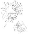
- FIG. 1 is an exploded perspective view of the lever type connector of the first embodiment.
- FIG. 2 is a perspective view showing a state before assembling the second housing to the first housing and the lever.
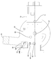
- FIG. 3 is a plan view including a partial cross section of the lever type connector in the state of FIG. 2 as viewed from above.
- FIG. 4 is a plan sectional view of the lever type connector when the second housing is in the unlocked position.
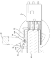
- FIG. 5 is a side view including a partial cross section seen from the left side of the lever type connector, showing a state in which the second housing is in the process of moving to the unlocked position.
- FIG. 6 is a side view including a cross section of the lever seen from the left side, showing a state in which the lever support member and the second housing are normally fitted.
- FIG. 7 is a side view of FIG. 6, further including a cross section of the lever support member and the second housing.
- FIG. 8 is a perspective view of a lever type connector showing a state in which the lever support member and the second housing are normally fitted.
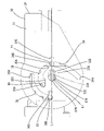
- FIG. 9 is a side view of the lever type connector as viewed from the left side, showing a state in which the lever is in the fitting position.
- FIG. 10 is a side view of the lever type connector as viewed from the left side, showing a state in which the lever is in the fitting detection position.
- FIG. 11 is an enlarged plan view of a part of the lever type connector when the lever is in the fitting detection position.
- FIG. 12 is a side view including a partial cross section seen from the left side of the lever type connector in a state where the lever is tilted forward after the lever support member and the second housing are normally fitted.
- the lever type connector of the present disclosure is (1) A housing unit having a first housing and a second housing that can be fitted to each other, A lever attached to the first housing and connecting the first terminal of the first housing and the second terminal of the second housing by rotating from the initial position to the fitting position. Equipped with The first housing includes a holding portion that holds the lever in the initial position. The lever has a temporary locking portion that is held in the initial position by locking to the holding portion. The second housing has a locking / releasing portion that releases the locked state of the temporary locking portion and the holding portion when assembled at the unlocking position with respect to the first housing.
- One of the lever and the housing unit has a rigid body portion and has a rigid body portion.
- the other of the lever and the housing unit has a spring piece that elastically deforms in the process of moving the second housing to the unlocked position.
- the spring piece starts elastic return when the second housing reaches the unlocked position and pushes the lever toward the fitting position.
- the lever holding / releasing structure holding part, temporary locking part, locking releasing part
- the structure for detecting the holding / releasing of the lever spring piece, rigid body part
- Each structure can function well. Therefore, when the second housing is assembled to the first housing, it is possible to satisfactorily detect the release of the lever.
- the first housing has a terminal holding member that holds the first terminal and a lever support member that supports the lever and can be fitted with the terminal holding member, and the lever support member has a lock portion.
- the second housing preferably has a lock arm that is locked to the lock portion to regulate the release from the lever support member, and the lock arm is preferably a spring piece.
- the lock arm has a function of restricting the detachment of the second housing from the lever support member and a function of pushing the lever toward the fitting position, so that it has a dedicated structure corresponding to each function. It is not necessary to provide a connector, and the connector configuration can be simplified.
- the second housing has a covering wall covering at least a part of the lock arm. According to this configuration, the presence of the covering wall makes it difficult for foreign matter or the like to come into contact with the lock arm, so that it is possible to prevent an erroneous operation in which the lock arm is unintentionally released. Further, it is possible to prevent excessive bending of the lock arm toward the covering wall side.
- the lock arm is pushed by the rigid body portion and bends during the fitting process of the lever support member and the second housing, and when the lever support member and the second housing are normally fitted, the lock arm is bent. It is preferable to elastically recover and lock the lock portion.
- the lock arm in the process of fitting the lever support member and the second housing, the lock arm is pushed by the rigid body portion to be in a bent state, thereby avoiding sliding contact between the lock arm and the lock portion. Can be done. Therefore, it is possible to prevent the lock arm and the lock portion from being deformed, and it is possible to maintain the locking allowance between the lock arm and the lock portion.
- FIGS. 1 to 12 The first embodiment of the lever type connector of the present disclosure will be described with reference to FIGS. 1 to 12.
- the directions appearing in FIGS. 1, 2, 5 to 10, 12 are defined as upward and downward as they are.
- the left and right sides appearing in FIGS. 1 to 10 and 12 are defined as front and back, respectively.
- the front and rear appearing in FIGS. 1, 2, 5 to 10, 12 are defined as right and left, respectively.
- the lever type connector 10 of the first embodiment includes a housing unit 20, a lever 30, a male terminal fitting (first terminal) 40, and a female terminal fitting (second terminal, not shown). , Is equipped.
- the housing unit 20 has a first housing 50 and a second housing 60. The first housing 50 and the second housing 60 can be fitted.
- the lever 30 is rotatably attached to the first housing 50.
- the first housing 50 accommodates the male terminal fitting 40.
- the first housing 50 includes a terminal holding member 70 and a lever support member 80.
- the terminal holding member 70 and the lever support member 80 are fitted according to the rotational operation of the lever 30.
- the terminal holding member 70 holds the male terminal fitting 40.
- the terminal holding member 70 is made of synthetic resin.
- the male terminal fitting 40 is fitted inside the terminal holding member 70.
- the terminal holding member 70 is formed in a shape close to a square cylinder. In the terminal holding member 70, five male terminal fittings 40 are housed in parallel in the left-right direction in three stages, upper and lower.
- a cam follower 71, a lock receiving portion 72, and a rotation restricting portion 73 are provided on the outer surfaces of both the left and right walls of the terminal holding member 70.
- the cam follower 71 is provided at the front end of the terminal holding member 70 and near the center in the vertical direction. The cam follower 71 is inserted into the cam groove 34 of the lever 30.
- the lock receiving portion 72 is provided on the rear end side of the corner portion (corner portion parallel to the front-rear direction) on the upper right end side of the terminal holding member 70.
- the lock receiving portion 72 is a longitudinal rib that projects outward in the left-right direction and extends in parallel in the front-rear direction.
- the lock receiving portion 72 projects like a hook with respect to the right wall surface of the terminal holding member 70.
- the second lock arm 39 of the lever 30, which will be described later, is locked to the lock receiving portion 72.
- the rotation restricting portion 73 projects outward from the center of both the left and right walls of the terminal holding member 70.
- the rotation restricting portion 73 is provided near the center of the terminal holding member 70 in the front-rear direction.
- the rotation restricting portion 73 is provided above the cam follower 71.
- the rotation restricting portion 73 is an L-shaped protruding piece when viewed from the vertical direction.
- the rotation restricting portion 73 maintains the locked state of the second lock arm 39 with respect to the lock receiving portion 72.
- the rotation restricting portion 73 regulates the bending deformation of the second lock arm 39 locked to the lock receiving portion 72.
- the lever support member 80 supports the lever 30.
- the lever support member 80 is made of synthetic resin.
- the lever support member 80 includes a hood portion 81 and a guide portion 82.
- the hood portion 81 has a square cylinder shape that opens forward.
- the hood portion 81 is fitted with a second housing 60, which will be described later, inside the hood portion 81.
- the back wall 83 of the hood portion 81 is provided with five insertion holes 84 (see FIG. 5) arranged side by side in three stages corresponding to the terminal accommodating chamber 61 of the second housing 60.
- the male terminal fitting 40 projects into the hood portion 81 (inside the terminal accommodating chamber 61 of the second housing 60) through the insertion hole 84 when the terminal holding member 70 and the lever support member 80 are normally fitted. Is placed.
- the hood portion 81 includes a pair of first groove portions (holding portions) 85, a pair of second groove portions 86, a pair of rotation shafts 87, and a pair of first regulation pins 88.
- a lock portion 89 and a lock portion 89 are provided.
- the first groove portion 85 is a groove extending rearward from the front end of the hood portion 81.
- a temporary locking portion 37A of the lever 30, which will be described later, is locked to the first groove portion 85.
- the second groove portion 86 is a groove extending forward from the rear end of the hood portion 81.
- the second groove portion 86 is provided so as to be separated downward from the first groove portion 85.
- the second regulation pin 62 of the second housing 60 which will be described later, is inserted into the second groove portion 86.
- the rotating shaft 87 protrudes from the outer surfaces of both the left and right walls of the hood portion 81.
- the rotation shaft 87 constitutes the rotation center of the lever 30 by being fitted into the bearing hole 33 of the lever 30, which will be described later.
- the rotating shaft 87 includes a shaft portion 87A and a rib 87B.
- the shaft portion 87A projects in a columnar shape from the outer surfaces of both the left and right walls of the hood portion 81.
- the rib 87B protrudes from the tip surface of the shaft portion 87A.
- the cross section of the rib 87B (the cross section orthogonal to the left-right direction) is rectangular.
- the first regulation pin 88 protrudes from the outer surfaces of both the left and right walls of the hood portion 81.
- the first regulation pin 88 is in sliding contact with the first regulation groove 35 of the lever 30, which will be described later.
- the first regulation pin 88 has a columnar shape.
- the first regulation pin 88 is arranged above the rotation shaft 87.
- the lock portion 89 is provided at the front end of the upper side wall portion of the hood portion 81.
- the lock portion 89 protrudes downward from the center in the left-right direction in a hook shape at the front end of the upper side wall portion of the hood portion 81.
- the lock portion 89 is locked by the first lock arm 64 of the second housing 60, which will be described later.
- the guide portion 82 guides the insertion of the male terminal fitting 40 into the hood portion 81 side.
- the guide portion 82 is provided with five guide grooves 82A, which are arranged in parallel on the left and right in parallel with the insertion hole 84, in three stages above and below.
- the guide groove 82A has a groove shape that is open upward and extends in the front-rear direction.
- the second housing 60 is made of synthetic resin. As shown in FIG. 1, the second housing 60 has a rectangular parallelepiped shape. As shown in FIG. 5, the second housing 60 includes a plurality of terminal accommodating chambers 61 for accommodating the male terminal fitting 40. The terminal accommodating chamber 61 has a form of penetrating the second housing 60 in the front-rear direction. The terminal accommodating chambers 61 are arranged in three stages above and below in parallel in the left-right direction.
- the second housing 60 is provided with a pair of second regulation pins 62, a pair of unlocking portions 63, a first lock arm (spring piece) 64, and a covering wall 65.
- the second regulation pin 62 on the left side and the unlocking portion 63 are visible.
- the second regulation pin 62 protrudes from the outer surface of both the left and right walls of the second housing 60.
- the second regulation pin 62 is in sliding contact with the second regulation groove 36 of the lever 30, which will be described later.
- the second regulation pin 62 is cylindrical.
- the second regulation pin 62 is arranged at substantially the same height as the cam follower 71 and the rotation shaft 87 in a state where the second housing 60 is assembled to the first housing 50.
- the second regulation pin 62, the cam follower 71, and the rotation shaft 87 are arranged on the virtual fitting line L1.
- the virtual fitting line L1 is a line that passes through the rotation center (rotating shaft 87) of the lever 30 and is parallel to the fitting direction of the first housing 50 and the second housing 60.
- the second regulation pin 62 is arranged below the first regulation pin 88.
- the unlocking portion 63 protrudes from the outer surfaces of both the left and right walls of the second housing 60.
- the locking release portion 63 releases the locked state of the temporary locking portion 37A and the first groove portion 85 described later. do.
- the unlocking portion 63 has a shape close to a rectangular parallelepiped shape that is long in the front-rear direction.
- the rear end of the unlocking portion 63 is provided with an inclined portion 63A that is inclined toward the center in the left-right direction toward the rear.
- the unlocking portion 63 is arranged on the upper side of the second regulation pin 62.
- the first lock arm 64 extends in a cantilever shape from the rear end on the upper surface of the second housing 60 and the central portion in the width direction toward the front.
- the first lock arm 64 bends and deforms in the vertical direction (the height direction, the direction approaching or separating from the upper surface of the second housing 60).
- a lock protrusion 64A projecting upward is provided at the center of the upper surface of the first lock arm 64 in the length direction.
- the rear surface of the lock protrusion 64A is inclined downward toward the rear when the first lock arm 64 is in the natural state.
- the front surface of the lock protrusion 64A extends in the vertical direction when the first lock arm 64 is in the natural state.
- An operation unit 64B is provided at a free end portion (front end portion) of the first lock arm 64.
- the operation unit 64B has a plate surface (upper surface) long in the left-right direction.
- the operation unit 64B is for performing a pressing operation for unlocking the first lock arm 64.
- the covering wall 65 is erected on the upper side of the front end portion of the second housing 60 so as to cover the operation portion 64B of the first lock arm 64.
- the covering wall 65 regulates the action of an unnecessary release operation force on the first lock arm 64.
- the male terminal fitting 40 is formed by bending a metal plate material. As shown in FIG. 1, the male terminal fitting 40 includes a box portion 41, a tab 42, and a crimping portion 43.
- the box portion 41 has a tubular shape.
- the lever 30 is rotatably attached to the lever support member 80 between the initial position and the fitting position.
- the lever 30 connects the male terminal fitting 40 of the first housing 50 and the female terminal fitting (not shown) of the second housing 60 by rotating from the initial position to the fitting position.
- the lever 30 includes a pair of arm portions 31 and a connecting portion 32.
- the arm portion 31 has a disk portion that covers the lever support member 80 from the left-right direction.
- the connecting portion 32 the plate surfaces of the pair of arm portions 31 face each other in the left-right direction.
- the connecting portion 32 connects a pair of arm portions 31.
- the arm portion 31 of the lever 30 is provided with a bearing hole 33, a cam groove 34, a first regulation groove 35, and a second regulation groove 36.
- the bearing hole 33 is a hole that penetrates in the plate thickness direction at the center position of the disk portion of the arm portion 31.
- the bearing hole 33 is fitted with a rotation shaft 87 of the first housing 50.
- the bearing hole 33 includes an inner hole 33A and an outer hole 33B.
- the inner hole 33A and the outer hole 33B are connected in the plate thickness direction of the arm portion 31.
- the inner hole 33A is provided in the inner portion of the arm portion 31 (the portion on the other arm portion 31 side). As shown in FIG.
- the inner hole 33A has a long oval shape along the virtual fitting line L1 when the lever 30 is in the fitting position described later.
- the shaft portion 87A of the rotating shaft 87 is inserted into the inner hole 33A.
- the outer hole 33B is provided in an outer portion of the arm portion 31 (a portion opposite to the other arm portion 31).
- the outer hole 33B has a keyhole shape.
- the outer hole 33B has a circular hole 33C and a shaft-side recess 33D.
- the circular hole 33C is provided at the center position of the arm portion 31.
- the shaft-side recess 33D is a form in which a part of the circular hole 33C is recessed. As shown in FIG. 9, the shaft-side recess 33D is recessed in the direction parallel to the virtual fitting line L1.
- the rib 87B of the rotation shaft 87 is inserted into the outer hole 33B.
- the cam groove 34 is provided in the arm portion 31 in an arc shape over a predetermined range around the bearing hole 33.
- One end 34A of the cam groove 34 is located slightly inside the peripheral edge of the arm portion 31.
- the other end 34B of the cam groove 34 is located on the virtual fitting line L1.
- the cam groove 34 has a shape that approaches the bearing hole 33 as it goes from one end 34A to the other end 34B.
- the cam follower 71 of the second housing 60 slides in the cam groove 34.
- the other end 34B of the cam groove 34 is provided with a cam-side recess 34C.
- the cam-side recess 34C extends radially outward of the arm portion 31 disk portion along the virtual fitting line L1 from the other end 34B of the cam groove 34.
- the first regulation groove 35 is provided in the arm portion 31 in an arc shape over a predetermined range around the bearing hole 33.
- the first regulation groove 35 has an arc shape concentric with the rotation center (rotation shaft 87) of the lever 30.
- the first regulation groove 35 slides the first regulation pin 88 of the first housing 50 into contact with the first regulation pin 88 in the rotation process of the lever 30.
- One end 35A of the first regulation groove 35 is provided at a position adjacent to the other end 34B of the cam groove 34.
- the other end 35B of the first regulation groove 35 is provided with an inner recess 35C.
- the inner recess 35C is a form in which a part of the cam groove 34 is recessed.
- the inner recess 35C extends from the other end 35B toward one end 35A in parallel with the virtual fitting line L1.
- the second regulation groove 36 is provided in the arm portion 31 in an arc shape over a predetermined range around the bearing hole 33.
- the second regulation groove 36 has an arc shape concentric with the rotation center (rotation shaft 87) of the lever 30.
- the second regulation groove 36 slides the second regulation pin 62 of the second housing 60 into contact with the second regulation pin 62 in the rotation process of the lever 30.
- the second regulation groove 36 is provided on the bearing hole 33 side of the arm portion 31 with respect to the first regulation groove 35.
- One end 36A of the second regulation groove 36 is provided slightly rearward (on the connecting portion 32 side) from the center of the rotation shaft 87.
- a detection recess 36C is provided at the other end 36B of the second regulation groove 36.
- the detection recess 36C is a form in which a part of the second regulation groove 36 is recessed.
- the detection recess 36C extends from the other end 36B of the second regulation groove 36 to the bearing hole 33 side along the virtual fitting line L1.
- the arm portion 31 is provided with an opening 36D (see FIG. 2) that is open to the outside so as to be connected to one end 36A of the second regulation groove 36.
- the arm portion 31 is provided with a groove portion 37.
- the groove portion 37 is provided at a position adjacent to the opening portion 36D on the connecting portion 32 side.
- the groove portion 37 has a shape in which the inner surface of the arm portion 31 (the surface on the other side of the arm portion 31) is recessed.
- a temporary locking portion 37A is provided on the inner surface of the groove portion 37.
- the temporary locking portion 37A is an elastic piece extending from the inner surface of the groove portion 37 toward the opening.
- the tip of the temporary locking portion 37A projects toward the other temporary locking portion 37A.
- the temporary locking portion 37A holds the lever 30 in the initial position by locking the first groove portion 85.
- the lever 30 is provided with a pair of rigid body portions 38.
- the rigid body portion 38 projects from the inner surface of the arm portion 31 (the surface on the other arm portion 31 side) toward the other arm portion 31 side.
- the rigid body portion 38 is provided at a position adjacent to the groove portion 37 on the connecting portion 32 side.
- the rigid body portion 38 has a shape close to a rectangular parallelepiped extending in a direction orthogonal to the direction (vertical direction in FIG. 5) along the concave direction of the axial side concave portion 33D.
- An inclined portion 38A is provided at the front lower end of the rigid body portion 38 in a state where the lever 30 is in the initial position (the state shown in FIG. 5).
- the inclined portion 38A is inclined downward toward the rear.
- the lever 30 is provided with a second lock arm 39 that can be flexed and deformed.
- the second lock arm 39 protrudes from the inner surface of the right arm portion 31 (the surface on the other arm portion 31 side).
- the second lock arm 39 extends along a direction parallel to the longitudinal direction of the rigid body portion 38.
- the second lock arm 39 is provided with a protrusion 39A at an intermediate position in the extending direction.
- the protrusion 39A is locked to the lock receiving portion 72.
- the tip of the second lock arm 39 is provided with a projecting piece 39B projecting back and forth.
- the lever 30 is provided with a pair of restricting pieces 39C facing the pair of protruding pieces 39B in the left-right direction.
- the protruding piece 39B interferes with the regulation piece 39C to regulate the excessive bending of the second lock arm 39.
- the assembly process of the lever type connector 10 will be described.
- the lever 30 is assembled to the first housing 50 (terminal holding member 70 and lever support member 80).
- the rear end of the guide portion 82 of the lever support member 80 is inserted inside the terminal holding member 70.
- the first housing 50 is inserted between the pair of arm portions 31 of the lever 30.
- the bearing hole 33 of the lever 30 is fitted to the rotation shaft 87 of the lever support member 80.
- the first regulation pin 88 of the lever support member 80 is inserted into the first regulation groove 35 of the lever 30.
- the second regulation pin 62 of the lever support member 80 is inserted into the second regulation groove 36 of the lever 30.
- FIG. 3 when the temporary locking portion 37A is locked to the first groove portion 85, the lever 30 is held at the initial position and is in the temporary locking state.
- the second housing 60 is assembled to the first housing 50 and the lever 30 assembled in the temporarily locked state (the state in which the lever 30 is held in the initial position) shown in FIG. From the state shown in FIG. 3 to the state shown in FIG. 4, the rear end side of the second housing 60 is inserted into the hood portion 81.
- the temporarily locked portion 37A and the first groove portion 85 are released from the locked state by the unlocked portion 63.
- the locking release portion 63 enters the first groove portion 85 and bends the temporary locking portion 37A outward in the left-right direction.
- the temporary locking portion 37A is disengaged from the first groove portion 85, and the locked state with the first groove portion 85 is released.
- the lever 30 can rotate between the initial position and the fitting position with the rotation shaft 87 as the rotation center.
- the first lock arm 64 comes into contact with the rigid body portion 38 of the lever 30 in the process of moving the second housing 60 to the unlocked position.
- the operation portion 64B of the first lock arm 64 is pushed downward (upper surface side of the second housing 60) by the rigid body portion 38.
- the first lock arm 64 is pushed by the rigid body portion 38 and elastically deforms and bends downward.
- the lock protrusion 64A does not come into contact with the lock portion 89 and is separated downward.
- the timing at which the operating portion 64B comes into contact with the rigid body portion 38 can be adjusted by changing the shape (inclination degree, etc.) of the inclined portion 38A.
- the second housing 60 reaches the unlocked position.
- the temporarily locked state of the lever 30 with respect to the lever support member 80 is released, so that the rigid body portion 38 can move.
- the first lock arm 64 starts elastic recovery and pushes and moves the lever 30 toward the fitting position.
- the operation unit 64B pushes the rigid body portion 38 upward (the side opposite to the upper surface of the second housing 60). As a result, it is possible to detect that the temporarily locked state of the lever 30 has been released.
- the rib 87B of the rotating shaft 87 is located in the circular hole 33C of the bearing hole 33.
- the cam follower 71 is located at one end 34A of the cam groove 34.
- the first regulation pin 88 is located at one end 35A of the first regulation groove 35.
- the second regulation pin 62 is located at one end 36A of the second regulation groove 36.
- the lever 30 When the lever 30 is tilted backward, as shown in FIG. 9, it rotates about the rotation shaft 87 and rotates to the fitting position.
- the cam follower 71 When the lever 30 is in the mating position, the cam follower 71 is located at the other end 34B of the cam groove 34.
- the first regulation pin 88 is located at the other end 35B of the first regulation groove 35.
- the second regulation pin 62 is located at the other end 36B of the second regulation groove 36.
- the lever 30 When the lever 30 reaches the fitting position, the first housing 50 and the second housing 60 are fitted in a facing positional relationship.
- the male terminal fitting 40 is arranged so as to project into the terminal accommodating chamber 61 through the insertion hole 84. As a result, the male terminal fitting 40 is connected to the female terminal fitting (not shown).
- the lever 30 After the lever 30 reaches the fitting position, as shown in FIG. 10, the lever 30 is slid from the rotation shaft 87 to the eccentric fitting detection position (rear position). In the process of sliding the lever 30 to the fitting detection position, the rib 87B enters the shaft side recess 33D. The cam follower 71 enters the cam side recess 34C. The first regulation pin 88 slides the inner recess 35C toward one end 35A. The second regulation pin 62 enters the detection recess 36C. By sliding the lever 30 in this way, it is possible to detect that the terminal holding member 70 and the lever support member 80 are fitted.
- the second lock arm 39 is locked to the lock receiving portion 72 of the second housing 60 as shown in FIG.
- the tip of the rotation restricting portion 73 (a portion parallel to the front-rear direction) is located between the second lock arm 39 and the right arm portion 31.
- the first lock arm 64 is pushed by the rigid body portion 38 by rotating the lever 30 from the fitting position side to the initial position. It bends and the locked state with the lock portion 89 is released. Therefore, the second housing 60 can be detached without directly pushing down the first lock arm 64. Since the first lock arm 64 can be pushed down by the action of the lever via the lever 30, the releasing force can be increased, and the lock strength of the first lock arm 64 can be increased.
- a structure for holding / releasing the lever 30 (first groove portion 85, temporary locking portion 37A, locking / releasing portion 63) and a structure for detecting the holding / releasing of the lever 30 (first lock arm 64, rigid body portion 38). ) Is provided as a separate structure, so that each structure can function well. Therefore, when the second housing 60 is assembled to the first housing 50, it is possible to satisfactorily detect the release of the lever 30.
- the first housing 50 of the present disclosure has a terminal holding member 70 that holds the male terminal fitting 40, and a lever support member 80 that supports the lever 30 and can be fitted with the terminal holding member 70.
- the second housing 60 has a first lock arm 64 that is locked to the lock portion 89 to regulate the release from the lever support member 80. According to this, since the first lock arm 64 has a function of restricting the detachment of the second housing 60 from the lever support member 80 and a function of pushing the lever 30 toward the fitting position side, each function is provided. It is not necessary to provide a dedicated structure corresponding to the above, and the configuration of the lever type connector 10 can be simplified.
- the second housing 60 of the present disclosure has a covering wall 65 that covers a part of the first lock arm 64. According to this, since foreign matter and the like are less likely to come into contact with the first lock arm 64 due to the presence of the covering wall 65, it is possible to prevent an erroneous operation in which the first lock arm 64 is unintentionally released. Further, it is possible to prevent excessive bending of the first lock arm 64 toward the covering wall 65 side.
- the first lock arm 64 of the present disclosure is pushed by the rigid body portion 38 and bends in the process of fitting the lever support member 80 and the second housing 60.
- the first lock arm 64 elastically returns and locks to the lock portion 89 when the lever support member 80 and the second housing 60 are normally fitted.
- the first lock arm 64 is pushed by the rigid body portion 38 to be in a bent state, so that the first lock arm 64 and the second lock arm 64 are locked. It is possible to avoid sliding contact of the portion 89. Therefore, it is possible to prevent the first lock arm 64 and the lock portion 89 from being deformed, and it is possible to maintain the locking allowance between the first lock arm 64 and the lock portion 89.
- the present invention is not limited to the embodiments described above and in the drawings, but is shown by the scope of claims.
- the present invention includes the meaning equivalent to the scope of claims and all modifications within the scope of claims, and is intended to include embodiments such as the following.
- the first housing 50 has a terminal holding member 70 and a lever supporting member 80 configured as separate bodies, but is composed of one member in which the terminal holding member and the lever supporting member are integrated. It may have been done.
- the lever 30 can be configured to fit the first housing and the second housing by rotating from the initial position to the fitting position.
- the second housing 60 may be configured to be located at the unlocked position at the start of assembling to the first housing 50.
- the rigid body portion 38 is provided on the lever 30, but it may be provided on the housing unit 20 (at least one of the terminal holding member 70, the lever support member 80, and the second housing 60). ..
- the spring piece (first lock arm 64) is provided on the lever support member 80, it may be provided on the lever 30. In this case, the spring piece does not have to function as a lock arm.
- the first lock arm 64 when the lever type connector 10 is unlocked, the first lock arm 64 is pushed by the rigid body portion 38 and bends downward, but the first lock arm 64 is pushed by the lock portion 89. It may be configured to bend downward.
Landscapes
- Details Of Connecting Devices For Male And Female Coupling (AREA)
Abstract
第2ハウジングの第1ハウジングへの組み付け時に、レバーの保持解除を良好に検知する。 レバー式コネクタ(10)の第2ハウジング(60)は、第1ハウジング(50)に対して係止解除位置に組み付けられたときに、仮係止部(37A)と第1溝部(85)の係止状態を解除する係止解除部(63)を有している。レバー(30)は、剛体部(38)を有している。ハウジングユニット(20)は、第2ハウジング(60)が係止解除位置へ移動する過程で弾性変形する第1ロックアーム(64)を有している。第1ロックアーム(64)は、第2ハウジング(60)が係止解除位置に到達したときに弾性復帰を開始してレバー(30)を嵌合位置側に押し動かす。
Description
本開示は、レバー式コネクタに関するものである。
特許文献1に開示されるレバー式コネクタは、第1のコネクタハウジングと、第2のコネクタハウジングと、嵌合操作レバーと、を備えている。嵌合操作レバーは、回動初期位置から回動終了位置まで回動可能に、第1のコネクタハウジングに収容されている。嵌合操作レバーは、カム溝を有している。第2のコネクタハウジングは、カム溝に入り込む嵌合用突起を有している。嵌合操作レバーは、回動初期位置から回動終了位置まで回動操作されると、カム溝によって嵌合用突起を引き込み、両ハウジングを嵌合完了状態にする。第1のコネクタハウジングは、嵌合操作レバーを回動初期位置に仮係止するレバー仮係止手段を有している。第2のコネクタハウジングは、両ハウジングを嵌合開始位置に突き合わせたときに、レバー仮係止手段による仮係止状態を解除する仮係止解除手段を有している。
特許文献1のレバー式コネクタでは、両ハウジングを嵌合開始位置に突き合わせたときに、嵌合操作レバーの弾性係止片が、撓み変形することでレバー係止手段から外れる。レバー係止手段から外れた弾性係止片が弾性復帰することで、嵌合操作レバーが微小回動し、レバーの係止解除を検知させる。このように、弾性係止片は、レバーを保持・解除する構造と、レバーの保持解除を検知させる構造とに用いられているため、レバーの保持解除を良好に検知することができないおそれがある。
本開示のレバー式コネクタは、上記のような事情に基づいて完成されたものであって、第2ハウジングの第1ハウジングへの組み付け時に、レバーの保持解除を良好に検知することができる。
本開示のレバー式コネクタは、
互いに嵌合可能な第1ハウジングと第2ハウジングとを有するハウジングユニットと、
前記第1ハウジングに取り付けられ、初期位置から嵌合位置へ回動することによって、前記第1ハウジングの第1端子と前記第2ハウジングの第2端子を接続させるレバーと、
を備え、
前記第1ハウジングは、前記レバーを前記初期位置に保持する保持部を具備し、
前記レバーは、前記保持部に係止することによって、前記初期位置に保持される仮係止部を有し、
前記第2ハウジングは、前記第1ハウジングに対して係止解除位置に組み付けられたときに、前記仮係止部と前記保持部の係止状態を解除する係止解除部を有し、
前記レバーおよび前記ハウジングユニットの一方は、剛体部を有し、
前記レバーおよび前記ハウジングユニットの他方は、前記第2ハウジングが前記係止解除位置へ移動する過程で弾性変形するばね片を有し、
前記ばね片は、前記第2ハウジングが前記係止解除位置に到達したときに弾性復帰を開始して前記レバーを前記嵌合位置側に押し動かすレバー式コネクタ。
互いに嵌合可能な第1ハウジングと第2ハウジングとを有するハウジングユニットと、
前記第1ハウジングに取り付けられ、初期位置から嵌合位置へ回動することによって、前記第1ハウジングの第1端子と前記第2ハウジングの第2端子を接続させるレバーと、
を備え、
前記第1ハウジングは、前記レバーを前記初期位置に保持する保持部を具備し、
前記レバーは、前記保持部に係止することによって、前記初期位置に保持される仮係止部を有し、
前記第2ハウジングは、前記第1ハウジングに対して係止解除位置に組み付けられたときに、前記仮係止部と前記保持部の係止状態を解除する係止解除部を有し、
前記レバーおよび前記ハウジングユニットの一方は、剛体部を有し、
前記レバーおよび前記ハウジングユニットの他方は、前記第2ハウジングが前記係止解除位置へ移動する過程で弾性変形するばね片を有し、
前記ばね片は、前記第2ハウジングが前記係止解除位置に到達したときに弾性復帰を開始して前記レバーを前記嵌合位置側に押し動かすレバー式コネクタ。
本開示によれば、第2ハウジングの第1ハウジングへの組み付け時に、レバーの保持解除を良好に検知することができる。
[本開示の実施形態の説明]
最初に本開示の実施形態を列記して説明する。
本開示のレバー式コネクタは、
(1)互いに嵌合可能な第1ハウジングと第2ハウジングとを有するハウジングユニットと、
前記第1ハウジングに取り付けられ、初期位置から嵌合位置へ回動することによって、前記第1ハウジングの第1端子と前記第2ハウジングの第2端子を接続させるレバーと、
を備え、
前記第1ハウジングは、前記レバーを前記初期位置に保持する保持部を具備し、
前記レバーは、前記保持部に係止することによって、前記初期位置に保持される仮係止部を有し、
前記第2ハウジングは、前記第1ハウジングに対して係止解除位置に組み付けられたときに、前記仮係止部と前記保持部の係止状態を解除する係止解除部を有し、
前記レバーおよび前記ハウジングユニットの一方は、剛体部を有し、
前記レバーおよび前記ハウジングユニットの他方は、前記第2ハウジングが前記係止解除位置へ移動する過程で弾性変形するばね片を有し、
前記ばね片は、前記第2ハウジングが前記係止解除位置に到達したときに弾性復帰を開始して前記レバーを前記嵌合位置側に押し動かす。
本開示の構成によれば、第2ハウジングを第1ハウジングに対して係止解除位置に組み付けることで、仮係止部と保持部の係止状態が解除されるため、初期位置でのレバーの保持状態が解除されることになる。第2ハウジングが係止解除位置に到達したときに、ばね片が弾性復帰を開始してレバーを嵌合位置側に押し動かすため、初期位置でのレバーの保持状態が解除されたことを検知することができる。その上で、レバーの保持・解除構造(保持部、仮係止部、係止解除部)と、レバーの保持解除を検知させる構造(ばね片、剛体部)とが別の構造として設けられるため、それぞれの構造を良好に機能させることができる。したがって、第2ハウジングの第1ハウジングへの組み付け時に、レバーの保持解除を良好に検知することができる。
(2)第1ハウジングは、第1端子を保持する端子保持部材と、レバーを支持し、端子保持部材と嵌合可能なレバー支持部材と、を有し、レバー支持部材は、ロック部を有し、第2ハウジングは、ロック部に係止してレバー支持部材からの離脱を規制するロックアームを有し、ロックアームは、ばね片であることが好ましい。この構成によれば、ロックアームが、第2ハウジングのレバー支持部材からの離脱を規制する機能と、レバーを嵌合位置側に押し動かす機能と、を兼備するため、各機能に対応した専用構造を設ける必要がなく、コネクタの構成を簡易にすることができる。
(3)(2)において、第2ハウジングは、ロックアームの少なくとも一部を覆う覆い壁を有していることが好ましい。この構成によれば、覆い壁の存在によってロックアームに異物などが接触し難くなるため、ロックアームが意図せず解除される誤操作を防止することができる。さらに、ロックアームの覆い壁側への過度撓みを防ぐことができる。
(4)(2)又は(3)において、ロックアームは、レバー支持部材と第2ハウジングの嵌合過程で、剛体部に押されて撓み、レバー支持部材と第2ハウジングの正規嵌合時に、弾性復帰してロック部に係止することが好ましい。この構成によれば、レバー支持部材と第2ハウジングの嵌合過程で、ロックアームが剛体部に押されて撓んだ状態にしておくことで、ロックアームとロック部の摺接を回避することができる。そのため、ロックアームとロック部の変形を防止することができ、ロックアームとロック部の係止代を保つことができる。
最初に本開示の実施形態を列記して説明する。
本開示のレバー式コネクタは、
(1)互いに嵌合可能な第1ハウジングと第2ハウジングとを有するハウジングユニットと、
前記第1ハウジングに取り付けられ、初期位置から嵌合位置へ回動することによって、前記第1ハウジングの第1端子と前記第2ハウジングの第2端子を接続させるレバーと、
を備え、
前記第1ハウジングは、前記レバーを前記初期位置に保持する保持部を具備し、
前記レバーは、前記保持部に係止することによって、前記初期位置に保持される仮係止部を有し、
前記第2ハウジングは、前記第1ハウジングに対して係止解除位置に組み付けられたときに、前記仮係止部と前記保持部の係止状態を解除する係止解除部を有し、
前記レバーおよび前記ハウジングユニットの一方は、剛体部を有し、
前記レバーおよび前記ハウジングユニットの他方は、前記第2ハウジングが前記係止解除位置へ移動する過程で弾性変形するばね片を有し、
前記ばね片は、前記第2ハウジングが前記係止解除位置に到達したときに弾性復帰を開始して前記レバーを前記嵌合位置側に押し動かす。
本開示の構成によれば、第2ハウジングを第1ハウジングに対して係止解除位置に組み付けることで、仮係止部と保持部の係止状態が解除されるため、初期位置でのレバーの保持状態が解除されることになる。第2ハウジングが係止解除位置に到達したときに、ばね片が弾性復帰を開始してレバーを嵌合位置側に押し動かすため、初期位置でのレバーの保持状態が解除されたことを検知することができる。その上で、レバーの保持・解除構造(保持部、仮係止部、係止解除部)と、レバーの保持解除を検知させる構造(ばね片、剛体部)とが別の構造として設けられるため、それぞれの構造を良好に機能させることができる。したがって、第2ハウジングの第1ハウジングへの組み付け時に、レバーの保持解除を良好に検知することができる。
(2)第1ハウジングは、第1端子を保持する端子保持部材と、レバーを支持し、端子保持部材と嵌合可能なレバー支持部材と、を有し、レバー支持部材は、ロック部を有し、第2ハウジングは、ロック部に係止してレバー支持部材からの離脱を規制するロックアームを有し、ロックアームは、ばね片であることが好ましい。この構成によれば、ロックアームが、第2ハウジングのレバー支持部材からの離脱を規制する機能と、レバーを嵌合位置側に押し動かす機能と、を兼備するため、各機能に対応した専用構造を設ける必要がなく、コネクタの構成を簡易にすることができる。
(3)(2)において、第2ハウジングは、ロックアームの少なくとも一部を覆う覆い壁を有していることが好ましい。この構成によれば、覆い壁の存在によってロックアームに異物などが接触し難くなるため、ロックアームが意図せず解除される誤操作を防止することができる。さらに、ロックアームの覆い壁側への過度撓みを防ぐことができる。
(4)(2)又は(3)において、ロックアームは、レバー支持部材と第2ハウジングの嵌合過程で、剛体部に押されて撓み、レバー支持部材と第2ハウジングの正規嵌合時に、弾性復帰してロック部に係止することが好ましい。この構成によれば、レバー支持部材と第2ハウジングの嵌合過程で、ロックアームが剛体部に押されて撓んだ状態にしておくことで、ロックアームとロック部の摺接を回避することができる。そのため、ロックアームとロック部の変形を防止することができ、ロックアームとロック部の係止代を保つことができる。
[本開示の実施形態の詳細]
[実施例1]
本開示のレバー式コネクタを具体化した実施例1を、図1~図12を参照して説明する。本実施例1において、上下の方向については、図1,2,5~10,12にあらわれる向きを、そのまま上方、下方と定義する。前後の方向については、図1~10,12にあらわれる左方、右方を、それぞれ前方、後方と定義する。左右の方向は、図1,2,5~10,12にあらわれる前方、後方を、それぞれ右方、左方と定義する。
[実施例1]
本開示のレバー式コネクタを具体化した実施例1を、図1~図12を参照して説明する。本実施例1において、上下の方向については、図1,2,5~10,12にあらわれる向きを、そのまま上方、下方と定義する。前後の方向については、図1~10,12にあらわれる左方、右方を、それぞれ前方、後方と定義する。左右の方向は、図1,2,5~10,12にあらわれる前方、後方を、それぞれ右方、左方と定義する。
(レバー式コネクタの構成)
本実施例1のレバー式コネクタ10は、図1に示すように、ハウジングユニット20と、レバー30と、雄端子金具(第1端子)40と、雌端子金具(第2端子、図示略)と、を備えている。ハウジングユニット20は、第1ハウジング50と、第2ハウジング60と、を有している。第1ハウジング50と第2ハウジング60は、嵌合可能である。レバー30は、第1ハウジング50に対して、回動可能に取り付けられている。
本実施例1のレバー式コネクタ10は、図1に示すように、ハウジングユニット20と、レバー30と、雄端子金具(第1端子)40と、雌端子金具(第2端子、図示略)と、を備えている。ハウジングユニット20は、第1ハウジング50と、第2ハウジング60と、を有している。第1ハウジング50と第2ハウジング60は、嵌合可能である。レバー30は、第1ハウジング50に対して、回動可能に取り付けられている。
第1ハウジング50は、雄端子金具40を収容する。第1ハウジング50は、図1に示すように、端子保持部材70と、レバー支持部材80と、を有している。端子保持部材70とレバー支持部材80は、後述するように、レバー30の回動動作に応じて嵌合する。端子保持部材70は、雄端子金具40を保持する。端子保持部材70は、合成樹脂製である。端子保持部材70の内側には、雄端子金具40が嵌まり込む。端子保持部材70は、角筒状に近い形状に形成されている。端子保持部材70には、上下三段で、5つの雄端子金具40が左右方向に並列して収容されている。端子保持部材70の左右両壁の外面には、カムフォロア71と、ロック受け部72と、回動規制部73と、が設けられている。カムフォロア71は、端子保持部材70の前端、かつ上下方向の中央付近に設けられている。カムフォロア71は、レバー30のカム溝34に挿入される。
ロック受け部72は、図1に示すように、端子保持部材70の右上端側の角部(前後方向に平行な角部)において、後端側に設けられている。ロック受け部72は、左右方向外側に突出し、前後方向に平行に延びる長手状のリブである。ロック受け部72は、端子保持部材70の右壁面に対して鉤状に突出している。ロック受け部72には、後述するレバー30の第2ロックアーム39が係止する。
回動規制部73は、図1に示すように、端子保持部材70の左右両壁の中心から外側に突出している。回動規制部73は、端子保持部材70の前後方向の中心付近に設けられている。回動規制部73は、カムフォロア71よりも上側に設けられている。回動規制部73は、上下方向から見てL字形の突出片である。回動規制部73は、ロック受け部72に対する第2ロックアーム39の係止状態を維持する。回動規制部73は、ロック受け部72に係止している第2ロックアーム39の撓み変形を規制する。
レバー支持部材80は、レバー30を支持する。レバー支持部材80は、合成樹脂製である。レバー支持部材80は、図1に示すように、フード部81と、ガイド部82とを備えている。フード部81は、前方に開口する角筒状である。フード部81は、内部に後述する第2ハウジング60を嵌合させる。フード部81の背壁83には、第2ハウジング60の端子収容室61に対応して左右に並列する5つの挿入孔84(図5参照)が三段設けられている。雄端子金具40は、後述するように、端子保持部材70とレバー支持部材80の正規嵌合時に、挿入孔84を介してフード部81内(第2ハウジング60の端子収容室61内)に突出して配置される。
フード部81には、図1に示すように、一対の第1溝部(保持部)85と、一対の第2溝部86と、一対の回動軸87と、一対の第1規制ピン88と、ロック部89と、が設けられている。なお、図1では、右側の回動軸87、および右側の第1規制ピン88のみが見えている。第1溝部85は、フード部81の前端から後方に向かって延びる溝である。第1溝部85には、後述するレバー30の仮係止部37Aが係止する。第2溝部86は、フード部81の後端から前方に向かって延びる溝である。第2溝部86は、第1溝部85に対して下方に離隔して設けられている。第2溝部86には、後述する第2ハウジング60の第2規制ピン62が挿入される。
回動軸87は、フード部81の左右両壁の外面から突出している。回動軸87は、後述するレバー30の軸受孔33に嵌合させることによって、レバー30の回動中心を構成する。回動軸87は、軸部87Aと、リブ87Bと、を備えている。軸部87Aは、フード部81の左右両壁の外面から円柱状に突出している。リブ87Bは、軸部87Aの先端面から突出している。リブ87Bの断面(左右方向に直交する断面)は、長方形状である。
第1規制ピン88は、フード部81の左右両壁の外面から突出している。第1規制ピン88は、後述するレバー30の第1規制溝35に摺接する。第1規制ピン88は、図1に示すように、円柱状である。第1規制ピン88は、回動軸87よりも上方側に配置されている。
ロック部89は、図5に示すように、フード部81の上側壁部の前端に設けられている。ロック部89は、フード部81の上側壁部の前端において、左右方向中央から下方に鉤状に突出している。ロック部89は、後述する第2ハウジング60の第1ロックアーム64が係止する。
ガイド部82は、雄端子金具40のフード部81側への挿入をガイドする。ガイド部82には、挿入孔84に対応して左右に並列する5つのガイド溝82Aが上下に三段設けられている。ガイド溝82Aは、上方側に開放された前後方向に延びる溝形状である。
第2ハウジング60は、合成樹脂製である。第2ハウジング60は、図1に示すように、直方体形状である。第2ハウジング60は、図5に示すように、雄端子金具40を収容するための複数の端子収容室61を備えている。端子収容室61は、第2ハウジング60を前後方向に貫通した形態である。端子収容室61は、上下三段で、左右方向に5つ並列して配置されている。
第2ハウジング60には、図1に示すように、一対の第2規制ピン62と、一対の係止解除部63と、第1ロックアーム(ばね片)64と、覆い壁65と、が設けられている。なお、図1では、左側の第2規制ピン62と、係止解除部63と、が見えている。第2規制ピン62は、第2ハウジング60の左右両壁の外面から突出している。第2規制ピン62は、後述するレバー30の第2規制溝36に摺接する。第2規制ピン62は、円柱状である。第2規制ピン62は、図6に示すように、第1ハウジング50に第2ハウジング60を組み付けた状態で、カムフォロア71及び回動軸87とほぼ同じ高さに配置されている。第2規制ピン62、カムフォロア71及び回動軸87は、仮想嵌合線L1上に配置されている。仮想嵌合線L1は、レバー30の回動中心(回動軸87)を通りかつ第1ハウジング50と第2ハウジング60の嵌合方向と平行な線である。第2規制ピン62は、第1規制ピン88よりも下方側に配置されている。
係止解除部63は、第2ハウジング60の左右両壁の外面から突出している。係止解除部63は、第2ハウジング60が第1ハウジング50に対して後述する係止解除位置に組み付けられたときに、後述する仮係止部37Aと第1溝部85の係止状態を解除する。係止解除部63は、前後方向に長い直方体形状に近い形状である。図3に示すように、係止解除部63の後端には、後方に向かって左右方向中央側に傾く傾斜部63Aが設けられている。係止解除部63は、図6に示すように、第2規制ピン62の上方側に配置されている。
第1ロックアーム64は、図2に示すように、第2ハウジング60の上面における後端かつ幅方向中央部から前方へ向けて片持ち状に延出している。第1ロックアーム64は、上下方向(高さ方向であり、第2ハウジング60の上面に対し接近あるいは離間する方向)に撓み変形する。第1ロックアーム64の上面の長さ方向中央部には、上方に突出するロック突部64Aが設けられている。ロック突部64Aの後面は、図7に示すように、第1ロックアーム64が自然状態にあるときに、後方に向かって下り傾斜になっている。ロック突部64Aの前面は、第1ロックアーム64が自然状態にあるときに、上下方向に延びている。第1ロックアーム64の自由端部(前端部)には、操作部64Bが設けられている。操作部64Bは、左右方向に長い板面(上面)を有している。操作部64Bは、第1ロックアーム64に対しロック解除のための押圧操作を行うためのものである。
覆い壁65は、図7に示すように、第2ハウジング60の前端部の上側において、第1ロックアーム64の操作部64Bを覆うように架設されている。覆い壁65は、第1ロックアーム64に不要な解除操作力が作用するのを規制する。
雄端子金具40は、金属板材を曲げ加工して形成されている。雄端子金具40は、図1に示すように、箱部41と、タブ42と、圧着部43と、を備えている。箱部41は、各筒形状である。
レバー30は、レバー支持部材80に対して、初期位置と嵌合位置との間で回動可能に取り付けられている。レバー30は、初期位置から嵌合位置へ回動することによって、第1ハウジング50の雄端子金具40と第2ハウジング60の雌端子金具(図示略)を接続させる。レバー30は、図1に示すように、一対のアーム部31と、連結部32と、を備えている。アーム部31は、レバー支持部材80を左右方向から覆う円板部分を有している。連結部32は、一対のアーム部31の板面は、左右方向で対向している。連結部32は、一対のアーム部31を連結している。
レバー30のアーム部31には、図1に示すように、軸受孔33と、カム溝34と、第1規制溝35と、第2規制溝36と、が設けられている。軸受孔33は、アーム部31の円板部分の中心位置で板厚方向に貫通する孔である。軸受孔33は、第1ハウジング50の回動軸87が嵌合する。軸受孔33は、内側孔33Aと、外側孔33Bと、を備えている。内側孔33Aと外側孔33Bは、アーム部31の板厚方向で連なっている。内側孔33Aは、アーム部31における内側部分(他方のアーム部31側の部分)に設けられている。内側孔33Aは、図9に示すように、レバー30が後述する嵌合位置にあるときに、仮想嵌合線L1に沿って長い長円状である。内側孔33Aには、回動軸87の軸部87Aが挿入される。外側孔33Bは、アーム部31における外側部分(他方のアーム部31とは反対側の部分)に設けられている。外側孔33Bは、鍵穴状である。外側孔33Bは、円孔33Cと、軸側凹部33Dと、を有している。円孔33Cは、アーム部31の中心位置に設けられている。軸側凹部33Dは、円孔33Cの一部を凹ませた形態である。軸側凹部33Dは、図9に示すように、仮想嵌合線L1に平行な方向に凹んでいる。外側孔33Bには、回動軸87のリブ87Bが挿入される。
カム溝34は、図9に示すように、アーム部31において、軸受孔33周りの所定範囲に亘って円弧状に設けられている。カム溝34の一端34Aは、アーム部31の周縁よりもわずかに内側に位置している。カム溝34の他端34Bは、仮想嵌合線L1上に位置している。カム溝34は、一端34Aから他端34Bに向かうにつれて、軸受孔33に近づく形状である。カム溝34内を、第2ハウジング60のカムフォロア71が摺動する。カム溝34の他端34Bには、カム側凹部34Cが設けられている。カム側凹部34Cは、カム溝34の他端34Bから仮想嵌合線L1に沿ってアーム部31円板部分の径方向外側に延出している。
第1規制溝35は、図9に示すように、アーム部31において、軸受孔33周りの所定範囲に亘って円弧状に設けられている。第1規制溝35は、レバー30の回動中心(回動軸87)と同心の円弧形をなしている。第1規制溝35は、レバー30の回動過程で、第1ハウジング50の第1規制ピン88を摺接させる。第1規制溝35の一端35Aは、カム溝34の他端34Bに隣接する位置に設けられている。第1規制溝35の他端35Bには、内側凹部35Cが設けられている。内側凹部35Cは、カム溝34の一部を凹ませた形態である。内側凹部35Cは、仮想嵌合線L1と平行に他端35Bから一端35Aに向かって延びている。
第2規制溝36は、図9に示すように、アーム部31において、軸受孔33周りの所定範囲に亘って円弧状に設けられている。第2規制溝36は、レバー30の回動中心(回動軸87)と同心の円弧形をなしている。第2規制溝36は、レバー30の回動過程で、第2ハウジング60の第2規制ピン62を摺接させる。第2規制溝36は、アーム部31における第1規制溝35よりも軸受孔33側に設けられている。第2規制溝36の一端36Aは、回動軸87の中心よりわずかに後方側(連結部32側)に設けられている。第2規制溝36の他端36Bには、検知凹部36Cが設けられている。検知凹部36Cは、第2規制溝36の一部を凹ませた形態である。検知凹部36Cは、第2規制溝36の他端36Bから仮想嵌合線L1に沿って軸受孔33側に延出している。アーム部31には、第2規制溝36の一端36Aに連なるように、外側に開放される開口部36D(図2参照)が設けられている。
アーム部31には、図1、図3に示すように、溝部37が設けられている。溝部37は、開口部36Dに対して連結部32側で隣り合う位置に設けられている。溝部37は、アーム部31の内面(他方のアーム部31側の面)を凹ませた形状である。溝部37の奥面には、仮係止部37Aが設けられている。仮係止部37Aは、溝部37の奥面から開口に向かって延びる弾性片である。仮係止部37Aの先端は、他方の仮係止部37A側に向かって突出している。仮係止部37Aは、第1溝部85に係止することによって、レバー30を初期位置に保持する。
レバー30には、図1に示すように、一対の剛体部38が設けられている。剛体部38は、アーム部31の内面(他方のアーム部31側の面)から他方のアーム部31側に向かって突出している。剛体部38は、溝部37に対して連結部32側で隣り合う位置に設けられている。剛体部38は、軸側凹部33Dの凹み方向に沿う方向(図5では上下方向)に直交する方向に延びる直方体に近い形状である。レバー30が初期位置にある状態(図5に示す状態)における剛体部38の前側下端には、傾斜部38Aが設けられている。傾斜部38Aは、後方に向かって下り傾斜になっている。
レバー30には、図1、図11に示すように、撓み変形可能な第2ロックアーム39が設けられている。第2ロックアーム39は、右側のアーム部31の内面(他方のアーム部31側の面)から突出している。第2ロックアーム39は、剛体部38の長手方向と平行な方向に沿って延びている。第2ロックアーム39には、図11に示すように、延出方向の途中位置に突起39Aが設けられている。突起39Aは、ロック受け部72に係止する。図11に示すように、第2ロックアーム39の先端には、前後にそれぞれ突出する突出片39Bが設けられている。レバー30には、一対の突出片39Bに左右方向でそれぞれ対向する一対の規制片39Cが設けられている。突出片39Bが規制片39Cに干渉することで、第2ロックアーム39の過度撓みを規制する。
(レバー式コネクタの組み立て工程)
レバー式コネクタ10の組み立て工程について説明する。図2に示すように、第1ハウジング50(端子保持部材70及びレバー支持部材80)に対してレバー30を組み付ける。レバー支持部材80のガイド部82の後端が、端子保持部材70の内側に挿入される。レバー30の一対のアーム部31の間に第1ハウジング50が挿入される。レバー支持部材80の回動軸87に、レバー30の軸受孔33を嵌合させる。レバー支持部材80の第1規制ピン88を、レバー30の第1規制溝35に挿入する。レバー支持部材80の第2規制ピン62を、レバー30の第2規制溝36に挿入する。図3に示すように、仮係止部37Aが第1溝部85に係止することによって、レバー30が初期位置に保持され、仮係止状態となる。
レバー式コネクタ10の組み立て工程について説明する。図2に示すように、第1ハウジング50(端子保持部材70及びレバー支持部材80)に対してレバー30を組み付ける。レバー支持部材80のガイド部82の後端が、端子保持部材70の内側に挿入される。レバー30の一対のアーム部31の間に第1ハウジング50が挿入される。レバー支持部材80の回動軸87に、レバー30の軸受孔33を嵌合させる。レバー支持部材80の第1規制ピン88を、レバー30の第1規制溝35に挿入する。レバー支持部材80の第2規制ピン62を、レバー30の第2規制溝36に挿入する。図3に示すように、仮係止部37Aが第1溝部85に係止することによって、レバー30が初期位置に保持され、仮係止状態となる。
図2に示す仮係止状態(レバー30が初期位置で保持された状態)で組み付けられた第1ハウジング50およびレバー30に対して、第2ハウジング60を組み付ける。図3に示す状態から図4に示す状態のように、第2ハウジング60の後端側をフード部81内に挿入する。第2ハウジング60は、第1ハウジング50に対して係止解除位置に組み付けられたときに、係止解除部63によって、仮係止部37Aと第1溝部85の係止状態が解除される。図4に示すように、係止解除部63は、第1溝部85内に入り込んで、仮係止部37Aを左右方向外側に撓ませる。仮係止部37Aは、第1溝部85から外れ、第1溝部85との係止状態が解除される。これにより、レバー30は、回動軸87を回動中心として、初期位置と嵌合位置との間で回動可能になる。
第1ロックアーム64は、第2ハウジング60が係止解除位置へ移動する過程で、レバー30の剛体部38に接触する。第1ロックアーム64の操作部64Bは、剛体部38に下方側(第2ハウジング60の上面側)に押される。第1ロックアーム64は、第2ハウジング60が係止解除位置へ移動する前に、剛体部38に押されて下方側に弾性変形して撓む。第2ハウジング60が係止解除位置へ移動する過程で、ロック突部64Aは、ロック部89に接触せず、下方側に離間している。操作部64Bが剛体部38に接触するタイミングは、傾斜部38Aの形状(傾き度合いなど)を変えることによって調整することができる。ロック突部64Aがロック部89よりも下方側に位置するように第1ロックアーム64を撓ませることで、第1ロックアーム64とロック突部64Aの摺接を回避することができる。
図7~図9に示すように、レバー支持部材80と第2ハウジング60が正規嵌合する時に、第2ハウジング60が係止解除位置に到達する。第2ハウジング60が係止解除位置に到達すると、レバー30のレバー支持部材80に対する仮係止状態が解除されるため、剛体部38が移動可能になる。第1ロックアーム64は、弾性復帰を開始して、レバー30を嵌合位置側に押し動かす。操作部64Bは、剛体部38を上方側(第2ハウジング60の上面とは反対側)に押し動かす。これにより、レバー30の仮係止状態が解除されたことを検知することができる。
図2に示すように、レバー30が初期位置にあるときに、回動軸87のリブ87Bは、軸受孔33の円孔33C内に位置している。カムフォロア71がカム溝34の一端34Aに位置する。第1規制ピン88は、第1規制溝35の一端35Aに位置する。第2規制ピン62は、図3に示すように、第2規制溝36の一端36Aに位置する。
レバー30を後方に傾倒させると、図9に示すように、回動軸87を中心に回動し、嵌合位置まで回動する。レバー30が嵌合位置にあるときに、カムフォロア71がカム溝34の他端34Bに位置する。第1規制ピン88は、第1規制溝35の他端35Bに位置する。第2規制ピン62は、第2規制溝36の他端36Bに位置する。レバー30が嵌合位置に到達すると、第1ハウジング50と第2ハウジング60が正対した位置関係で嵌合する。雄端子金具40は、挿入孔84を介して端子収容室61内に突出して配置される。これにより、雄端子金具40が雌端子金具(図示略)に接続される。
レバー30が嵌合位置に到達した後、図10に示すように、レバー30を回動軸87から偏心した嵌合検知位置(後方側の位置)へスライドする。レバー30が嵌合検知位置へスライドする過程で、リブ87Bが軸側凹部33Dに進入する。カムフォロア71は、カム側凹部34Cに進入する。第1規制ピン88は、内側凹部35Cを一端35A側に摺動する。第2規制ピン62は、検知凹部36Cに進入する。このようにレバー30をスライドさせることで、端子保持部材70とレバー支持部材80が嵌合したことを検知することができる。
レバー30が嵌合検知位置へスライドする過程で、第2ロックアーム39は、図11に示すように、第2ハウジング60のロック受け部72に係止する。回動規制部73の先端(前後方向に平行な部分)は、第2ロックアーム39と右側のアーム部31との間に位置する。これにより、第2ロックアーム39の右側のアーム部31側への撓み変形が規制され、ロック受け部72に対する第2ロックアーム39の係止状態が保持される。そのため、レバー30の初期位置側への回動が規制される。
(ロック解除操作)
両ハウジング50,60のロック解除操作について説明する。レバー30が嵌合位置側にある状態において、図12に示すようにレバー30を前方に傾倒させる(初期位置に戻す)と、第1ロックアーム64が剛体部38に押されて下方(第2ハウジング60の上面側)に撓む。ロック突部64Aがロック部89よりも下方側に位置するように第1ロックアーム64を撓ませることで、ロック突部64Aとロック部89の係止状態が解除される。このようにレバー30を前方に傾倒させた状態(第1ロックアーム64を撓ませた状態)で、第2ハウジング60がレバー支持部材80から離脱可能になる。例えば、第1ハウジング50が車両に固定されている構成では、レバー30の解除操作(前方に傾倒させる操作)を行いながら、第2ハウジング60を離脱させる操作が可能になる。
両ハウジング50,60のロック解除操作について説明する。レバー30が嵌合位置側にある状態において、図12に示すようにレバー30を前方に傾倒させる(初期位置に戻す)と、第1ロックアーム64が剛体部38に押されて下方(第2ハウジング60の上面側)に撓む。ロック突部64Aがロック部89よりも下方側に位置するように第1ロックアーム64を撓ませることで、ロック突部64Aとロック部89の係止状態が解除される。このようにレバー30を前方に傾倒させた状態(第1ロックアーム64を撓ませた状態)で、第2ハウジング60がレバー支持部材80から離脱可能になる。例えば、第1ハウジング50が車両に固定されている構成では、レバー30の解除操作(前方に傾倒させる操作)を行いながら、第2ハウジング60を離脱させる操作が可能になる。
このように、レバー支持部材80と第2ハウジング60の正規嵌合時に、レバー30を嵌合位置側から初期位置へ回動させることで、第1ロックアーム64は、剛体部38に押されて撓み、ロック部89との係止状態が解除される。したがって、第1ロックアーム64を直接押し下げる操作を行うことなく、第2ハウジング60を離脱させることができる。レバー30を介したテコの作用によって第1ロックアーム64を押し下げることができるため、解除力を高めることができ、ひいては第1ロックアーム64のロック強度を高めることができる。
(本実施例の効果)
以上のように、本開示のレバー式コネクタ10によれば、第2ハウジング60を第1ハウジング50に対して係止解除位置に組み付けることで、仮係止部37Aと第1溝部85の係止状態が解除されるため、初期位置でのレバー30の保持状態が解除されることになる。第2ハウジング60が係止解除位置に到達したときに、第1ロックアーム64が弾性復帰を開始してレバー30を嵌合位置側に押し動かすため、初期位置でのレバー30の保持状態が解除されたことを検知することができる。その上で、レバー30の保持・解除構造(第1溝部85、仮係止部37A、係止解除部63)と、レバー30の保持解除を検知させる構造(第1ロックアーム64、剛体部38)とが別の構造として設けられるため、それぞれの構造を良好に機能させることができる。したがって、第2ハウジング60の第1ハウジング50への組み付け時に、レバー30の保持解除を良好に検知することができる。
以上のように、本開示のレバー式コネクタ10によれば、第2ハウジング60を第1ハウジング50に対して係止解除位置に組み付けることで、仮係止部37Aと第1溝部85の係止状態が解除されるため、初期位置でのレバー30の保持状態が解除されることになる。第2ハウジング60が係止解除位置に到達したときに、第1ロックアーム64が弾性復帰を開始してレバー30を嵌合位置側に押し動かすため、初期位置でのレバー30の保持状態が解除されたことを検知することができる。その上で、レバー30の保持・解除構造(第1溝部85、仮係止部37A、係止解除部63)と、レバー30の保持解除を検知させる構造(第1ロックアーム64、剛体部38)とが別の構造として設けられるため、それぞれの構造を良好に機能させることができる。したがって、第2ハウジング60の第1ハウジング50への組み付け時に、レバー30の保持解除を良好に検知することができる。
本開示の第1ハウジング50は、雄端子金具40を保持する端子保持部材70と、レバー30を支持し、端子保持部材70と嵌合可能なレバー支持部材80と、を有している。第2ハウジング60は、ロック部89に係止してレバー支持部材80からの離脱を規制する第1ロックアーム64を有している。これによれば、第1ロックアーム64が、第2ハウジング60のレバー支持部材80からの離脱を規制する機能と、レバー30を嵌合位置側に押し動かす機能と、を兼備するため、各機能に対応した専用構造を設ける必要がなく、レバー式コネクタ10の構成を簡易にすることができる。
本開示の第2ハウジング60は、第1ロックアーム64の一部を覆う覆い壁65を有している。これによれば、覆い壁65の存在によって第1ロックアーム64に異物などが接触し難くなるため、第1ロックアーム64が意図せず解除される誤操作を防止することができる。さらに、第1ロックアーム64の覆い壁65側への過度撓みを防ぐことができる。
本開示の第1ロックアーム64は、レバー支持部材80と第2ハウジング60の嵌合過程で、剛体部38に押されて撓む。第1ロックアーム64は、レバー支持部材80と第2ハウジング60の正規嵌合時に、弾性復帰してロック部89に係止する。これによれば、レバー支持部材80と第2ハウジング60の嵌合過程で、第1ロックアーム64が剛体部38に押されて撓んだ状態にしておくことで、第1ロックアーム64とロック部89の摺接を回避することができる。そのため、第1ロックアーム64とロック部89の変形を防止することができ、第1ロックアーム64とロック部89の係止代を保つことができる。
[他の実施例]
本発明は、上記記述及び図面によって説明した実施例に限定されるものではなく、特許請求の範囲によって示される。本発明には、特許請求の範囲と均等の意味及び特許請求の範囲内でのすべての変更が含まれ、下記のような実施形態も含まれることが意図される。
上記実施例1では、第1ハウジング50は、別体として構成される端子保持部材70とレバー支持部材80を有していたが、端子保持部材とレバー支持部材が一体化された一部材で構成されていてもよい。この場合、レバー30は、初期位置から嵌合位置へ回動することによって、第1ハウジングと第2ハウジングとを嵌合させる構成とすることができる。この場合、第2ハウジング60は、第1ハウジング50に対する組み付け開始時点で、係止解除位置に位置する構成とすることができる。
上記実施例1では、剛体部38がレバー30に設けられていたが、ハウジングユニット20(端子保持部材70、レバー支持部材80、及び第2ハウジング60の少なくともいずれか)に設けられていてもよい。ばね片(第1ロックアーム64)がレバー支持部材80に設けられていたが、レバー30に設けられていてもよい。この場合、ばね片はロックアームとして機能するものでなくてもよい。
上記実施例1では、レバー式コネクタ10のロック解除操作時、第1ロックアーム64が剛体部38に押されて下方に撓む構成であったが、第1ロックアーム64がロック部89に押されて下方に撓む構成であってもよい。
本発明は、上記記述及び図面によって説明した実施例に限定されるものではなく、特許請求の範囲によって示される。本発明には、特許請求の範囲と均等の意味及び特許請求の範囲内でのすべての変更が含まれ、下記のような実施形態も含まれることが意図される。
上記実施例1では、第1ハウジング50は、別体として構成される端子保持部材70とレバー支持部材80を有していたが、端子保持部材とレバー支持部材が一体化された一部材で構成されていてもよい。この場合、レバー30は、初期位置から嵌合位置へ回動することによって、第1ハウジングと第2ハウジングとを嵌合させる構成とすることができる。この場合、第2ハウジング60は、第1ハウジング50に対する組み付け開始時点で、係止解除位置に位置する構成とすることができる。
上記実施例1では、剛体部38がレバー30に設けられていたが、ハウジングユニット20(端子保持部材70、レバー支持部材80、及び第2ハウジング60の少なくともいずれか)に設けられていてもよい。ばね片(第1ロックアーム64)がレバー支持部材80に設けられていたが、レバー30に設けられていてもよい。この場合、ばね片はロックアームとして機能するものでなくてもよい。
上記実施例1では、レバー式コネクタ10のロック解除操作時、第1ロックアーム64が剛体部38に押されて下方に撓む構成であったが、第1ロックアーム64がロック部89に押されて下方に撓む構成であってもよい。
10…レバー式コネクタ
20…ハウジングユニット
30…レバー
31…アーム部
32…連結部
33…軸受孔
33A…内側孔
33B…外側孔
33C…円孔
33D…軸側凹部
34…カム溝
34A…一端
34B…他端
34C…カム側凹部
35…第1規制溝
35A…一端
35B…他端
35C…内側凹部
36…第2規制溝
36A…一端
36B…他端
36C…検知凹部
36D…開口部
37…溝部
37A…仮係止部
38…剛体部
38A…傾斜部
39…第2ロックアーム
39A…突起
39B…突出片
39C…規制片
40…雄端子金具(第1端子)
41…箱部
42…タブ
43…圧着部
50…第1ハウジング
60…第2ハウジング
61…端子収容室
62…第2規制ピン
63…係止解除部
63A…傾く傾斜部
64…第1ロックアーム(ばね片、ロックアーム)
64A…ロック突部
64B…操作部
65…覆い壁
70…端子保持部材
71…カムフォロア
72…ロック受け部
73…回動規制部
80…レバー支持部材
81…フード部
82…ガイド部
82A…ガイド溝
83…背壁
84…挿入孔
85…第1溝部(保持部)
86…第2溝部
87…回動軸
87A…軸部
87B…リブ
88…第1規制ピン
89…ロック部
L1…仮想嵌合線
20…ハウジングユニット
30…レバー
31…アーム部
32…連結部
33…軸受孔
33A…内側孔
33B…外側孔
33C…円孔
33D…軸側凹部
34…カム溝
34A…一端
34B…他端
34C…カム側凹部
35…第1規制溝
35A…一端
35B…他端
35C…内側凹部
36…第2規制溝
36A…一端
36B…他端
36C…検知凹部
36D…開口部
37…溝部
37A…仮係止部
38…剛体部
38A…傾斜部
39…第2ロックアーム
39A…突起
39B…突出片
39C…規制片
40…雄端子金具(第1端子)
41…箱部
42…タブ
43…圧着部
50…第1ハウジング
60…第2ハウジング
61…端子収容室
62…第2規制ピン
63…係止解除部
63A…傾く傾斜部
64…第1ロックアーム(ばね片、ロックアーム)
64A…ロック突部
64B…操作部
65…覆い壁
70…端子保持部材
71…カムフォロア
72…ロック受け部
73…回動規制部
80…レバー支持部材
81…フード部
82…ガイド部
82A…ガイド溝
83…背壁
84…挿入孔
85…第1溝部(保持部)
86…第2溝部
87…回動軸
87A…軸部
87B…リブ
88…第1規制ピン
89…ロック部
L1…仮想嵌合線
Claims (4)
- 互いに嵌合可能な第1ハウジングと第2ハウジングとを有するハウジングユニットと、
前記第1ハウジングに取り付けられ、初期位置から嵌合位置へ回動することによって、前記第1ハウジングの第1端子と前記第2ハウジングの第2端子を接続させるレバーと、
を備え、
前記第1ハウジングは、前記レバーを前記初期位置に保持する保持部を具備し、
前記レバーは、前記保持部に係止することによって、前記初期位置に保持される仮係止部を有し、
前記第2ハウジングは、前記第1ハウジングに対して係止解除位置に組み付けられたときに、前記仮係止部と前記保持部の係止状態を解除する係止解除部を有し、
前記レバーおよび前記ハウジングユニットの一方は、剛体部を有し、
前記レバーおよび前記ハウジングユニットの他方は、前記第2ハウジングが前記係止解除位置へ移動する過程で弾性変形するばね片を有し、
前記ばね片は、前記第2ハウジングが前記係止解除位置に到達したときに弾性復帰を開始して前記レバーを前記嵌合位置側に押し動かすレバー式コネクタ。 - 前記第1ハウジングは、
前記第1端子を保持する端子保持部材と、
前記レバーを支持し、前記端子保持部材と嵌合可能なレバー支持部材と、
を有し、
前記レバー支持部材は、ロック部を有し、
前記第2ハウジングは、前記ロック部に係止して前記レバー支持部材からの離脱を規制するロックアームを有し、
前記ロックアームは、前記ばね片である請求項1に記載のレバー式コネクタ。 - 前記第2ハウジングは、前記ロックアームの少なくとも一部を覆う覆い壁を有している請求項2に記載のレバー式コネクタ。
- 前記ロックアームは、
前記レバー支持部材と前記第2ハウジングの嵌合過程で、前記剛体部に押されて撓み、
前記レバー支持部材と前記第2ハウジングの正規嵌合時に、弾性復帰して前記ロック部に係止する請求項2又は請求項3に記載のレバー式コネクタ。
Priority Applications (2)
| Application Number | Priority Date | Filing Date | Title |
|---|---|---|---|
| US18/032,178 US20230396021A1 (en) | 2020-11-05 | 2021-10-15 | Lever-type connector |
| CN202180071961.XA CN116349095A (zh) | 2020-11-05 | 2021-10-15 | 杆式连接器 |
Applications Claiming Priority (2)
| Application Number | Priority Date | Filing Date | Title |
|---|---|---|---|
| JP2020-185011 | 2020-11-05 | ||
| JP2020185011A JP2022074713A (ja) | 2020-11-05 | 2020-11-05 | レバー式コネクタ |
Publications (1)
| Publication Number | Publication Date |
|---|---|
| WO2022097451A1 true WO2022097451A1 (ja) | 2022-05-12 |
Family
ID=81457112
Family Applications (1)
| Application Number | Title | Priority Date | Filing Date |
|---|---|---|---|
| PCT/JP2021/038192 Ceased WO2022097451A1 (ja) | 2020-11-05 | 2021-10-15 | レバー式コネクタ |
Country Status (4)
| Country | Link |
|---|---|
| US (1) | US20230396021A1 (ja) |
| JP (1) | JP2022074713A (ja) |
| CN (1) | CN116349095A (ja) |
| WO (1) | WO2022097451A1 (ja) |
Families Citing this family (1)
| Publication number | Priority date | Publication date | Assignee | Title |
|---|---|---|---|---|
| DE102024207725A1 (de) * | 2024-08-14 | 2026-02-19 | Robert Bosch Gesellschaft mit beschränkter Haftung | Steckverbinder und Steckverbinderanordnung |
Citations (6)
| Publication number | Priority date | Publication date | Assignee | Title |
|---|---|---|---|---|
| JPH05251134A (ja) * | 1992-03-02 | 1993-09-28 | Yazaki Corp | コネクタの結合装置 |
| JPH08330023A (ja) * | 1995-05-29 | 1996-12-13 | Amp Japan Ltd | レバー式コネクタ |
| JP2003022874A (ja) * | 2001-07-06 | 2003-01-24 | Sumitomo Wiring Syst Ltd | レバー式コネクタ |
| JP2003264034A (ja) * | 2002-03-11 | 2003-09-19 | Calsonic Kansei Corp | セルフロケートコネクタ |
| JP2003264036A (ja) * | 2002-03-08 | 2003-09-19 | Sumitomo Wiring Syst Ltd | レバー式コネクタ |
| JP2011023127A (ja) * | 2009-07-13 | 2011-02-03 | Sumitomo Wiring Syst Ltd | レバー式コネクタ |
Family Cites Families (1)
| Publication number | Priority date | Publication date | Assignee | Title |
|---|---|---|---|---|
| JP6335457B2 (ja) * | 2013-09-17 | 2018-05-30 | 矢崎総業株式会社 | レバー式コネクタ |
-
2020
- 2020-11-05 JP JP2020185011A patent/JP2022074713A/ja active Pending
-
2021
- 2021-10-15 WO PCT/JP2021/038192 patent/WO2022097451A1/ja not_active Ceased
- 2021-10-15 CN CN202180071961.XA patent/CN116349095A/zh active Pending
- 2021-10-15 US US18/032,178 patent/US20230396021A1/en active Pending
Patent Citations (6)
| Publication number | Priority date | Publication date | Assignee | Title |
|---|---|---|---|---|
| JPH05251134A (ja) * | 1992-03-02 | 1993-09-28 | Yazaki Corp | コネクタの結合装置 |
| JPH08330023A (ja) * | 1995-05-29 | 1996-12-13 | Amp Japan Ltd | レバー式コネクタ |
| JP2003022874A (ja) * | 2001-07-06 | 2003-01-24 | Sumitomo Wiring Syst Ltd | レバー式コネクタ |
| JP2003264036A (ja) * | 2002-03-08 | 2003-09-19 | Sumitomo Wiring Syst Ltd | レバー式コネクタ |
| JP2003264034A (ja) * | 2002-03-11 | 2003-09-19 | Calsonic Kansei Corp | セルフロケートコネクタ |
| JP2011023127A (ja) * | 2009-07-13 | 2011-02-03 | Sumitomo Wiring Syst Ltd | レバー式コネクタ |
Also Published As
| Publication number | Publication date |
|---|---|
| JP2022074713A (ja) | 2022-05-18 |
| CN116349095A (zh) | 2023-06-27 |
| US20230396021A1 (en) | 2023-12-07 |
Similar Documents
| Publication | Publication Date | Title |
|---|---|---|
| JP5029872B2 (ja) | レバー式コネクタ | |
| CN101350479B (zh) | 杆型连接器 | |
| JP5360987B2 (ja) | レバー式コネクタ | |
| US7641485B2 (en) | Lever-type connector and a connector assembly | |
| JP3538750B2 (ja) | レバー式コネクタ | |
| JP3987736B2 (ja) | レバー式コネクタ | |
| JP5682476B2 (ja) | コネクタ | |
| JP4395784B2 (ja) | レバー式コネクタ | |
| JP6927108B2 (ja) | レバー式コネクタ | |
| WO2022097451A1 (ja) | レバー式コネクタ | |
| CN114914742B (zh) | 连接器 | |
| JP2011034843A (ja) | レバー式コネクタ | |
| JP3912263B2 (ja) | レバー式コネクタ | |
| JP2022074713A5 (ja) | ||
| JP5594008B2 (ja) | コネクタ | |
| JP7453067B2 (ja) | コネクタセット | |
| WO2021187050A1 (ja) | レバー式コネクタ | |
| JP5440462B2 (ja) | コネクタ | |
| WO2022049946A1 (ja) | レバー式コネクタ | |
| WO2022059276A1 (ja) | レバー式コネクタ | |
| JP4597852B2 (ja) | コネクタ | |
| JPH09147973A (ja) | レバー式コネクタ | |
| JP2016018636A (ja) | レバー式コネクタ | |
| JP4548198B2 (ja) | レバー式コネクタ | |
| JP4442502B2 (ja) | レバー式コネクタ |
Legal Events
| Date | Code | Title | Description |
|---|---|---|---|
| 121 | Ep: the epo has been informed by wipo that ep was designated in this application |
Ref document number: 21889004 Country of ref document: EP Kind code of ref document: A1 |
|
| WWE | Wipo information: entry into national phase |
Ref document number: 18032178 Country of ref document: US |
|
| NENP | Non-entry into the national phase |
Ref country code: DE |
|
| 122 | Ep: pct application non-entry in european phase |
Ref document number: 21889004 Country of ref document: EP Kind code of ref document: A1 |